EP1964795B1 - Vorrichtung zum Reinigen von Flüssigkeitssubstanzen, die auf ein Förderband gesprüht wurden - Google Patents
Vorrichtung zum Reinigen von Flüssigkeitssubstanzen, die auf ein Förderband gesprüht wurden Download PDFInfo
- Publication number
- EP1964795B1 EP1964795B1 EP08151831A EP08151831A EP1964795B1 EP 1964795 B1 EP1964795 B1 EP 1964795B1 EP 08151831 A EP08151831 A EP 08151831A EP 08151831 A EP08151831 A EP 08151831A EP 1964795 B1 EP1964795 B1 EP 1964795B1
- Authority
- EP
- European Patent Office
- Prior art keywords
- belt
- roller
- cleaning
- reverse roller
- conveyor
- Prior art date
- Legal status (The legal status is an assumption and is not a legal conclusion. Google has not performed a legal analysis and makes no representation as to the accuracy of the status listed.)
- Not-in-force
Links
Images


Classifications
-
- B—PERFORMING OPERATIONS; TRANSPORTING
- B65—CONVEYING; PACKING; STORING; HANDLING THIN OR FILAMENTARY MATERIAL
- B65G—TRANSPORT OR STORAGE DEVICES, e.g. CONVEYORS FOR LOADING OR TIPPING, SHOP CONVEYOR SYSTEMS OR PNEUMATIC TUBE CONVEYORS
- B65G45/00—Lubricating, cleaning, or clearing devices
- B65G45/10—Cleaning devices
- B65G45/22—Cleaning devices comprising fluid applying means
-
- B—PERFORMING OPERATIONS; TRANSPORTING
- B05—SPRAYING OR ATOMISING IN GENERAL; APPLYING FLUENT MATERIALS TO SURFACES, IN GENERAL
- B05B—SPRAYING APPARATUS; ATOMISING APPARATUS; NOZZLES
- B05B14/00—Arrangements for collecting, re-using or eliminating excess spraying material
- B05B14/20—Arrangements for collecting, re-using or eliminating excess spraying material from moving belts, e.g. filtering belts or conveying belts
-
- B—PERFORMING OPERATIONS; TRANSPORTING
- B65—CONVEYING; PACKING; STORING; HANDLING THIN OR FILAMENTARY MATERIAL
- B65G—TRANSPORT OR STORAGE DEVICES, e.g. CONVEYORS FOR LOADING OR TIPPING, SHOP CONVEYOR SYSTEMS OR PNEUMATIC TUBE CONVEYORS
- B65G45/00—Lubricating, cleaning, or clearing devices
- B65G45/10—Cleaning devices
- B65G45/12—Cleaning devices comprising scrapers
- B65G45/14—Moving scrapers
-
- B—PERFORMING OPERATIONS; TRANSPORTING
- B65—CONVEYING; PACKING; STORING; HANDLING THIN OR FILAMENTARY MATERIAL
- B65G—TRANSPORT OR STORAGE DEVICES, e.g. CONVEYORS FOR LOADING OR TIPPING, SHOP CONVEYOR SYSTEMS OR PNEUMATIC TUBE CONVEYORS
- B65G45/00—Lubricating, cleaning, or clearing devices
- B65G45/10—Cleaning devices
- B65G45/24—Cleaning devices comprising plural diverse cleaning devices
Definitions
- the invention concerns a device for cleaning a fluid substance from a conveyor belt which is endlessly wound and driven around at least two end rollers, at least one of which is motor-driven.
- the invention relates to the conveyor belts of machines and plants for painting, dyeing or impregnating processes, referred to below in short and for the sake of simplicity as "painting machines", which convey the articles to be treated through a chamber for spraying the fluid treatment substance, such as paint for example.
- the conveyor belt is formed by two sections: an upper outward section, on which the articles to be treated are usually rested, said articles, when they pass through the spraying chamber, being coated with the paint spray, and a lower return section, which is situated outside the said spraying chamber and which is soiled with paint and must be cleaned before returning to the upper level, in order to recover the residual paint and ensure that the clean conveyor is able to receive new articles.
- the devices currently used to recover the residual paint and clean the belt comprise means for removing said residual paint collected by the belt during coating of the parts, by means of a shaving or scraping operation, and comprise cleaning systems which in synchronism wet the belt with solvent and then dry it, for example using fixed doctor blades or rotating cylinders or a combination of these means.
- the cleaning device comprises a steel cylinder or roller with a smooth surface, which acts on the return section of the conveyor with a parallel arrangement for example facing the end drive roller of the said conveyor and this steel roller is made to rotate in the opposite direction to the direction of feeding of the belt, so as to perform effective shaving-off of the residual paint which is then detached from this roller by scraping means and collected in a recovery hopper.
- the said counter-rotating cleaning roller also called a reverse roller
- the said counter-rotating cleaning roller is partially immersed with a bottom portion thereof inside a solvent-containing tank so as to be cleaned and convey a film of the said solvent into the zone of contact with the lower section of the belt to be cleaned, in order to wet the belt zone from which the paint is removed and ensure that the said conveyor section leaves the reverse roller with a small amount of solvent which has the function of softening further any residual paint which can thus be more easily removed by following cleaning means comprising a further reverse roller and/or fixed doctor blades and/or rotating brushes and any other suitable means.
- This reverse-roller cleaning system has, over time, proved to be very valid and advantageous, but poses problems associated with the accumulation of paint on the doctor blade for initial scraping of the said reverse roller, especially when the paint is very dense, so much so that in these cases the said doctor blade is immersed during operation inside the solvent tank which thus becomes contaminated with paint, so that the solvent must be continually removed and renewed.
- the secondary cleaning belt owing to the said arrangement at an angle in plan view with respect to the belt to be cleaned, progressively brings into contact with this main belt portions thereof which are always clean and which, after contact, move away from the main belt with a vectorial component which is both longitudinal and transverse, the latter being opposite to the direction of feeding of the said main belt, thus preventing accumulation of the removed paint on the secondary belt.
- the invention proposes a device which combines the solutions of the known devices considered above such that it offers the advantages of these devices but not their defects.
- the device according to the invention as described in Claim 1 and the following depending claims, is essentially characterized by the use of a reverse roller making contact with the lower section of the main conveyor to be cleaned and by the use of a secondary conveyor belt, as per the second solution mentioned above, for cleaning the said reverse roller.
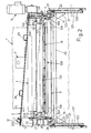
- T denotes the conveyor of the painting machine and R denotes the end drive roller of this conveyor underneath which the reverse roller 1 operates in a parallel arrangement making contact with the said conveyor, said reverse roller being made of chrome-plated steel and rotating in the same direction F of rotation as the drive roller R, so as to operate on the lower section of the conveyor T with an action opposing the feeding movement of this section, so as to perform vigorous recovery of the paint and cleaning of the said conveyor by means of a vigorous action.
- the scope of the invention also includes the solution where the reverse roller 1 operates in contact with a portion of the lower section of the conveyor T situated downstream of the end drive roller R and retained so that there is a suitable degree of interference with the same cleaning roller 1 by auxiliary drive means.
- the upper section of a cleaning conveyor belt 2 operates by means of tangential contact with the generatrix of a bottom zone of the reverse roller 1, said cleaning conveyor belt being made of a suitable composite, flexible, material, for example such as that used for the main belt T, and being positioned with its longitudinal axis in the direction of the length of the roller 1 and having a length suitably greater than that of this roller 1.
- the conveyor 2 is supported by a strong longitudinal inner frame 3 which is fixed in any suitable manner to the parallel side walls 104 of the main frame 4 of the device which also rotatably supports the end spindles of the reverse roller 1 actuated by a gear motor unit 5 ( Fig.
- 102 and 202 denote the drive rollers of the conveyor 2, the first of which rollers is driven idle and supported by a pair of tensioning plates fixed to the said frame 3, while the other roller 202 is motor-driven, is supported without adjustment by the said frame 3 and/or by a side support 30 (see below) fixed to the adjacent side wall 104 and is actuated by means which, for example, derive the rotational movement from the said gear motor 5 for rotation of the reverse roller 1, as will be described more fully below.
- the upper section of the cleaning conveyor 2 travels in the direction indicated by the arrow F1 shown in Figure 2 , namely in the direction of the motor-driven roller 202. From this figure it can be seen how the longitudinal axis of the cleaning conveyor 2 is inclined with respect to the axis of the reverse roller 1 so as to form an acute angle diverging towards the said motor-driven roller 202. The amount of this inclination depends on the width of the belt 2 since the upper section of this belt touches one end of the roller 1 with a portion close to its opposite side and touches the other end of the said reverse roller 1 with a portion close to its other side.
- the cleaning belt 2 is also characterized by an inclined position of its upper section with respect to the horizontal plane, since this section forms with the ideal vertical plane which passes through the contact zone between belt 2 and reverse roller 1 an angle of less than 90°.
- This transverse inclination has the effect that the paint removed by the belt 2 remains owing to the effect of gravity on the said belt and allows, where necessary, the introduction, via specific supply means 6, of a small continuous quantity of solvent into the contact zone between belt 2 and roller 1, in order to facilitate removal of the paint by the said belt 2.
- the upper section of the belt 2 travels over a sufficiently flexible surface 7 which is made of metal and/or other suitable material and which interacts with the said belt over the entire length of the upper roller 1 and which projects from the ends of this roller with sections of suitable length, where the said surface 7 has transverse gutter channels 107 and the same surface 7 projects by a suitable amount laterally from the bottom side of the conveyor 2 and terminates with the said channels 107 above a collection tank 8 which is fixed to the frame via the side walls 104 and the bottom wall of which has an inclination for example in the form of a double surface sloping downwards, with a discharge outlet 108 at the lowest point, for evacuating the liquid which drips from above (see below) into a collection tank 9 provided with recirculation pumps (not shown) and positioned in any suitable manner underneath the device in question.
- a sufficiently flexible surface 7 which is made of metal and/or other suitable material and which interacts with the said belt over the entire length of the upper roller 1 and which projects from the ends of this roller with sections of suitable
- the part which remains attached to the upper section of the conveyor 2 passes beyond the drive roller 202 where an anti-spray casing 10 is provided and on the lower return section of the said conveyor 2 the said paint is detached for example by means of at least one transverse and inclined doctor blade 11, with an active part made of an elastomer, a suitable plastic or spring steel.
- the paint detached by the doctor blade 11 falls into a hopper 12 into which the bottom edge of the said casing 10 drains and from this hopper the said paint is discharged into a container or into other suitable collection and removal means, not shown.
- the said belt 2 is provided internally, on the higher side, with a raised bead 302, for example with a trapezoidal cross-section, which is solid and continuous or formed by a succession of teeth, as in drive belts, said bead sliding guided inside corresponding annular grooves of the drive rollers 102 and 202 and at least along the upper section of the said conveyor 2 sliding inside a guide groove of suitable cross-section 207 formed longitudinally in the highest part of the portion with which the laminated surface 7 is fixed to the frame 3 supporting the conveyor 2.
- a raised bead 302 for example with a trapezoidal cross-section, which is solid and continuous or formed by a succession of teeth, as in drive belts, said bead sliding guided inside corresponding annular grooves of the drive rollers 102 and 202 and at least along the upper section of the said conveyor 2 sliding inside a guide groove of suitable cross-section 207 formed longitudinally in the highest part of the portion with which the laminated surface 7 is fixed to the frame 3 supporting the conveyor 2.
- the scope of the invention also includes the constructional variants where the sliding surface 7 may be perfectly rigid and flat or which envisage the use of means other than the inflatable tube 13, for example a rigid and/or spring-loaded pressing device, using solutions known for example in the sector of devices for cleaning the rollers of rotary printing machines.
- a second roller 100 for cleaning the lower section of the main conveyor T which has a length slightly greater than that of the said roller 1, is for example chrome-plated or lined with a fabric or cloth with suitable characteristics, also rotates in the direction F of the reverse roller 1 and is situated at a very small distance and/or so as to make substantially light contact with the latter, so that in the zone of mutual contact the two rollers are in any case able to move in opposite directions, without a negative reaction.
- This solution of using several reverse rollers arranged alongside each other and in succession is for example of the type described in document No.
- the roller 100 is also rotatably supported at the ends by the said side walls 104 and the ends of the two rollers 1 and 100 may, for example, be provided with closing shoulders 16 which operate in substantial contact with the ends of the said two rollers and with the lower section of the conveyor T, so as to define a tank which has limited contact with the external environment and is situated very close to the main conveyor T and into which solvent is continuously introduced by at least one supply pipe 17. Part of this solvent falls downwards through the free space existing between the rollers 1 and 100 and is collected by the surface 7 which conveys it by means of gravity into the collection tank 8.
- Part of the same solvent introduced by the pipe 17 is conveyed upwards by the rising surface of the reverse roller 1, in order to facilitate the removal of paint performed by this roller and in order to soften the residual paint which remains on the main conveyor T, so that it may then be more easily removed by the finishing roller 100 which, as mentioned, also operates with an action of the reverse type.
- Another part of said solvent supplied by the pipe 17 follows the surface of the roller 100 and facilitates the finishing action of this component.
- the side walls 104 of the frame 4 for supporting the device in question may for example be provided externally, on the end side for entry into the said painting machine, with lateral grooved pins which have a groove 19 and corresponding roller wheels 20 at a lower level ( Figs. 1 , 3 ).
- the painting machine may be provided, for example, on its side walls ( Fig.
- the guides 121 are interconnected by at least one cross-member 23 which is fixed via special diagonal end plates 123 to the inner sides of the said guides 121, and the ends of this cross-member 23 have, transversely fixed thereto, supports 24 which are provided with an upper groove 124 for centred engagement the said grooved pins 19 and provided with vertical flat tracks 224 on which the said wheels 20 slide and rest.
- Special adjustment means may be provided on the wheels 20 and/or on the said pins 19, for example in the form of cam-type supports for the said components, in order to ensure precise operating conditions of the device, also in the case where the said device and the means which constrain it in a movable manner to the painting machine have not been constructed in a absolutely precise manner.
- the side of the frame 3 which is directed outwards is provided, for example, with handles 25 which may be used by the operator to extract the device from the painting machine, for any verification and maintenance purposes and so as to allow subsequent reinsertion of the device in the operating position, locking means (not shown) which can be released if necessary being provided for this purpose in order to keep the device correctly in the operating position or allow extraction thereof.
- the driving power being derived for example from a gear motor 5.
- a drive 26 for example of the toothed pulley and belt type ( Fig.
Landscapes
- Engineering & Computer Science (AREA)
- Mechanical Engineering (AREA)
- Coating Apparatus (AREA)
- Cleaning By Liquid Or Steam (AREA)
- Rollers For Roller Conveyors For Transfer (AREA)
Claims (14)
- Vorrichtung zum Reinigen von Fluidsubstanzen, die auf ein auf Walzen getriebenes Band gesprüht wurden, insbesondere für Maschinen zum Aufsprühen von Farbe oder anderen Produkten vom Typ, der eine Umlenkwalze (1) aufweist, die ein Stahlzylinder oder eine Walze mit einer glatten Oberfläche ist, welche auf dem Rücklaufabschnitt des Bandes (T) mit einer parallelen Anordnung arbeitet, z. B. unter Gegenüberstellen der Endantriebswalze (R) des Förderers, und welche in einer Richtung entgegengesetzt der Zuführrichtung des Rücklaufabschnittes des Bandes rotiert, um ein wirksames Abschaben der restlichen Farbe vorzunehmen, die durch Abkratzmittel von dieser Umlenkwalze (1) entfernt und innerhalb eines Regenerierungstanks gesammelt wird, dadurch gekennzeichnet, dass diese Abkratzmittel auf die Erzeugende einer Bodenzone der Unlenkwalze (1) einwirken in Einklang mit einem entsprechenden Längsteil des oberen Abschnittes eines Reinigungsförderbandes (2), welches aus geeignetem, flexiblem Verbundmaterial hergestellt ist, z. B. ähnlich jenem, welches für den Hauptförderer (T) verwendet wird, wobei es mit seiner Längsachse in der Längsrichtung der Umlenkwalze (1) angeordnet ist.
- Vorrichtung nach Anspruch 1, bei welcher das Reinigungsförderband (2) eine Länge hat, die passend größer ist als die der Umlenkwalze (1), um mit passenden Endteilen von letzterer vorzustehen, und das Reinigungsband (2) schräg zu der horizontalen Ebene geneigt ist, um mit der Umlenkwalze (1) einen geeigneten Sammeltank zu bilden, der an den Enden offen ist, und auch bezüglich der Achse der Umlenkwalze (1) derart geneigt ist, dass das meiste der Breite des oberen Abschnittes des Reinigungsbandes an einem Zusammenwirken mit der Umlenkwalze (1) beteiligt ist, wobei das Reinigungsband (2) fortlaufend von Mitteln derart betätigt wird, dass ihr oberer Abschnitt in der Richtung (F1) läuft, längs welcher die Längsachse dieses Bandes (2) allmählich von der Achse der Umlenkwalze divergiert, so dass die von der Umlenkwalze entfernte Farbe schnell von dieser Walze weggefördert wird.
- Vorrichtung nach einem oder mehreren der vorhergehenden Ansprüche, dadurch gekennzeichnet, dass sie auch aufweist:- Mittel zum Reinigen des Rücklaufabschnittes des Reinigungsbandes (2);- Mittel zum Verhindern von Querbewegungen dieses Reinigungsbandes (2);- Mittel zum Sammeln und Leiten der Farbe von der Umlenkwalze und von dem Reinigungsband (2) zu Regenerierungsmitteln hin;- Mittel zum Sicherstellen eines geeigneten und gleichmäßigen Kontaktdruckes zwischen dem oberen Abschnitt des Reinigungsbandes (2) und der Umlenkwalze (1), um eine wirksame Reinigung dieser Walze sicherzustellen.
- Vorrichtung nach einem oder mehreren der vorhergehenden Ansprüche, dadurch gekennzeichnet, dass sie notwendigenfalls mindestens eine Düse (6) aufweist zum Einführen eines Lösungsmittels in den Tank, der an den Enden offen ist und durch das Reinigungsband (2) mit einer Querneigung und durch die Umlenkwalze (1) gebildet ist, um eine Trennung der Farbe von dieser Walze durch das Band (2) zu ermöglichen.
- Vorrichtung nach einem oder mehreren der vorhergehenden Ansprüche, bei welcher das Reinigungsförderband (2) von einem festen, länglichen inneren Rahmen (3) gehalten wird, der an den parallelen Seitenwänden (104) des Hauptrahmens (4) der Vorrichtung befestigt ist, welche auch die Endachszapfen der Umlenkwalze (1) drehbar abstützen und durch mindestens ein weiteres Querteil (204) verbunden sind, wobei die Antriebswalzen (102, 202) des Reinigungsbandes (2) von den Enden des Rahmens (3) über Paare von Platten gehalten sind, die teilweise fest und teilweise einstellbar sind, wobei ins Auge gefasst ist, dass der obere Abschnitt des Reinigungsbandes (2) über eine Oberfläche (7) läuft, die aus Metall und/oder einem anderen geeigneten Material hergestellt ist und über die gesamte Länge der oberen Walze (1) mit dem Band zusammenwirkt und von letzterer mit Endabschnitten übersteht, wo diese Oberfläche quer verlaufende Ablaufrinnenkanäle (107) hat und die Oberfläche (7) um einen passenden Betrag seitlich von der Bodenseite des Reinigungsbandes (2) übersteht und über einem Sammeltank (8) endet, der an dem Hauptrahmen (4) der Vorrichtung befestigt ist, wobei der Boden all dieser Teile eine Neigung in der Form einer nach unten schräg verlaufenden Oberfläche hat mit mindestens einem Abgangsauslass (108) am untersten Punkt für das Entleeren der von oben tropfenden Flüssigkeit in einen Sammeltank (9), der unter der in Rede stehenden Vorrichtung angeordnet ist.
- Vorrichtung nach einem oder mehreren der vorhergehenden Ansprüche, dadurch gekennzeichnet , dass verhindert wird, dass der obere Abschnitt des Reinigungsbandes (2) durch den Druck abgelenkt wird, welcher von der Umlenkwalze (1) quer auf diesen ausgeübt wird, wobei das Band (2) innen auf der höheren Seite mit mindestens einer erhabenen Wulst (302) versehen ist, die unter Führung innerhalb entsprechender Winkelnuten in den Umlenkwalzen (102, 202) dieses Bandes (2) gleitet und mindestens längs des oberen Abschnittes dieses Reinigungsbandes (2) innerhalb eines Führungskanals (207) gleitet, der längs in dem höheren Teil desjenigen Teils gebildet ist, bei welchem die Oberfläche (7) an dem das Reinigungsförderband (2) haltenden Rahmen (3) befestigt ist.
- Vorrichtung nach einem oder mehreren der vorhergehenden Ansprüche, bei welcher ein gekrümmtes Antisprüh-Gehäuse (10) gegenüber der Endantriebswalze (202) des Reinigungsförderbandes (2) vorgesehen ist und auf den unteren Rücklaufabschnitt des Bandes (2) durch mindestens ein Abstreifmesser bzw. eine Rakel und/oder ein anderes geeignetes Mittel (11) eingewirkt wird, welches die Farbe von diesem Band entfernt und sie in einen Trichter (12) hinein fallen lässt, in welchen die Farbe von der Bodenkante des Gehäuses (10) auch tropft, und von diesem Trichter dieselbe Farbe in einen Behälter oder in andere geeignete Sammel- und Entsorgungsmittel fällt.
- Vorrichtung nach einem oder mehreren der vorhergehenden Ansprüche, dadurch gekennzeichnet, dass zum Sicherstellen eines gleichmäßig verteilten Kontaktes zwischen dem oberen Abschnitt des flexiblen Reinigungsbandes (2) und der Umlenkwalze (1) der Teil des Bandes (2), welcher mit der Erzeugenden der Walze (1) Kontakt machen muss, gegen diese Walze durch einen entsprechenden Teil der darunterliegenden Oberfläche (7) gedrückt wird, welcher vollständig oder teilweise mit Flexibilitätseigenschaften gebildet ist und der unter Einwirken auf diesen eine Pressvorrichtung hat, die z. B. durch einen flexiblen Schlauch (13) gebildet ist, der mit einem Druckfluid aufgeblasen ist, z. B. Luft mit geeignetem Druck, wobei dieser Schlauch innerhalb eines Kanals (14) angeordnet ist, der auf dem das Förderband (2) halternden Rahmen (3) und parallel zu der Kontaktzone zwischen dem Band (2) und der Umlenkwalze (1) befestigt ist.
- Vorrichtung nach Anspruch 8, dadurch gekennzeichnet, dass entsprechend einer Konstruktionsvariante die Oberfläche (7), auf welcher der obere Abschnitt des Reinigungsbandes (2) gleitet, mindestens in der Zone perfekt starr und flach sein kann, wo sie mit diesem Band Kontakt hat.
- Vorrichtung nach Anspruch 8, bei welcher andere Mittel als der aufblasbare Schlauch (13), z. B. eine starre und/oder abgefederte Druckvorrichtung unter Verwendung von Lösungen übernommen werden kann, die z. B. auf dem Gebiet von Vorrichtungen zum Reinigen von Walzen bzw. Rollen von Rotationsdruckmaschinen bekannt sind.
- Vorrichtung nach einem oder mehreren der vorhergehenden Ansprüche, dadurch gekennzeichnet, dass eine zweite Walze (100) zum Reinigen des unteren Abschnittes des Hauptförderers (T) parallel zu der Umlenkwalze (1) und abstromig von dieser vorgesehen sein kann mit einer Länge, die etwas größer ist als jene der Umlenkwalze (1), wobei diese Walze z. B. mit Stoff oder Tuch mit geeigneten Eigenschaften belegt ist und auch in Richtung der Umlenkwalze (1) rotiert und in einem sehr kleinen Abstand und/oder so angeordnet ist, dass mit letzterer ein merklich schwacher Kontakt derart hergestellt wird, dass in der Zone gegenseitiger Berührung die zwei Walzen sich jedenfalls in entgegen gesetzten Richtungen bewegen können ohne eine negative Reaktion, wobei diese zweite Walze (100) an den Enden auch durch die Seitenwände (104) des Hauptrahmens (4) der Vorrichtung drehbar gehaltert ist und die Enden der zwei benachbarten Walzen (1, 100) mit Schließschultern (16) versehen sein können, die in erheblichem Kontakt mit den Enden der Walzen und mit dem unteren Abschnitt des Hauptförderers (T) arbeiten, um einen Tank zu bilden, der mit der äußeren Umgebung einen begrenzten Kontakt hat und sehr dicht an dem Hauptförderer (T) liegt und in welchen Lösungsmittel kontinuierlich durch mindestens ein Zuführrohr (17) eingeführt wird, wobei das Lösungsmittel teilweise durch den zwischen den zwei Walzen (1, 100) befindlichen freien Raum fällt und teilweise von der darunter liegenden Oberfläche (7) gesammelt wird, welche es mittels Schwerkraft in den Sammeltank (8) hinein fördert, während ein anderer Teil des Lösungsmittels von der ansteigenden Oberfläche der Umlenkwalze (1) nach oben transportiert wird, um das Entfernen von Farbe, welches von dieser Walze geleistet wird, zu erleichtern und die restliche Farbe aufzuweichen, die auf dem Hauptband (T) verbleibt, so dass die Farbe danach leichter von der Endbehandlungswalze (100) entfernt werden kann, während ein weiterer Teil des Lösungsmittels der Oberfläche der zweiten Walze (100) folgt und die Endbehandlung dieser Komponente ermöglicht und teilweise auf dem Hauptförderer (T) bleibt, um irgendeine Restfarbe aufzuweichen, welche dann endgültig von einer Endbearbeitungsrakel (18) entfernt wird, die mit ihren Enden auf den Seitenwänden (104) über bekannte dazwischen angeordnete Einstellmittel angebracht ist.
- Vorrichtung nach einem oder mehreren der vorhergehenden Ansprüche, dadurch gekennzeichnet, dass sie Mittel aufweist zur Vereinfachung des Antriebes aller Drehkomponenten, wobei die Antriebskraft z. B. von dem Getriebemotor (5) abgeleitet wird, welcher die Umkehrwalze (1) antreibt, wobei ein Antrieb (26) z. B. vom Riemen- oder Zahnriementyp für diesen Zweck zum Übertragen der Drehbewegung von der Umlenkwalze (1) auf die abstromige Walze (100) vorgesehen ist, während auf der anderen Seite der Vorrichtung die Drehbewegung von dieser zweiten Walze (100) mittels eines Winkelantriebs (27) und dann einer Transmission (28) mit Achsen erhalten wird, die parallel zueinander und senkrecht zu den Walzen (1, 100) liegen, von wo sich eine Transmission mit Welle und Kardangelenken (29) erstreckt, die auch auf der Halterung (30) angebracht sind, die auch bei der Drehabstützung der Antriebsriemenscheibe (202) des Reinigungsförderbandes (2) hilft.
- Vorrichtung nach einem oder mehreren der vorhergehenden Ansprüche, dadurch gekennzeichnet, dass sie auf der Färbemaschine angebracht sein kann und die Seitenwände (104) des Rahmens (4) außen auf der Eingangsseite in die Färbemaschine hinein mit seitlichen Nutenstiften (19) und entsprechenden Walzenrädern (20) auf niedriger Höhe vorgesehen sein kann, während die Färbemaschine auf ihren Seitenwänden mit horizontalen Führungen (21) mit C-förmigem Profil versehen ist, die mit dem hohlen Teil aufeinander zu gerichtet sind und die mit dem äußersten Ende mit Überstand auf ihrer Innenseite zusammengesetzte Räder (22) abstützen, welche innerhalb entsprechender Führungen (121) mit einem C-förmigen Profil laufen, die mit den vorgenannten Führungen (21) identisch sind und ihrerseits auf ihrem Ende in der Färbemaschine zusammengesetzte Räder (122) tragen, die innerhalb der Führungen (21) laufen, wobei die Führungen (121) durch mindestens ein Querteil (23) verbunden sind, die an den Innenseiten dieser Führungen (121) befestigt sind, und die Enden dieses Querteiles (23) mit Queranbringung an diesem Halterungen (24) haben, die mit einer oberen Nut (124) für den zentrierten Eingriff mit den Nutenstiften (19) versehen sind und die mit vertikalen und flachen Laufbahnen (224) versehen sind, auf welchen die Räder laufen und gegen welche sie sich abstützen (20).
- Vorrichtung nach Anspruch 13, dadurch gekennzeichnet, dass sie Einstellmittel z. B. vom Nockentyp aufweist, um ein präzises Einstellen des Zustandes der Vorrichtung zu ermöglichen, z. B. zum präzisen Einstellen der Beeinflussbarkeit zwischen der Umlenkwalze (1) und dem zu reinigenden Förderer (T) der Färbemaschine.
Applications Claiming Priority (1)
| Application Number | Priority Date | Filing Date | Title |
|---|---|---|---|
| IT000124A ITBO20070124A1 (it) | 2007-02-27 | 2007-02-27 | "dispositivo per pulire un nastro trasportatore rinviato su rulli, da sostanze fluide spruzzate sullo stesso, particolarmente per macchine spruzzatrici di vernice o d'altri prodotti" |
Publications (2)
| Publication Number | Publication Date |
|---|---|
| EP1964795A1 EP1964795A1 (de) | 2008-09-03 |
| EP1964795B1 true EP1964795B1 (de) | 2010-04-07 |
Family
ID=39414892
Family Applications (1)
| Application Number | Title | Priority Date | Filing Date |
|---|---|---|---|
| EP08151831A Not-in-force EP1964795B1 (de) | 2007-02-27 | 2008-02-22 | Vorrichtung zum Reinigen von Flüssigkeitssubstanzen, die auf ein Förderband gesprüht wurden |
Country Status (4)
| Country | Link |
|---|---|
| EP (1) | EP1964795B1 (de) |
| DE (1) | DE602008000917D1 (de) |
| ES (1) | ES2344170T3 (de) |
| IT (1) | ITBO20070124A1 (de) |
Cited By (2)
| Publication number | Priority date | Publication date | Assignee | Title |
|---|---|---|---|---|
| US8727101B2 (en) | 2011-06-24 | 2014-05-20 | Cefla Societa' Cooperativa | Device for cleaning fluid substances from a conveyor belt including paint, varnish and like products |
| EP3593909B1 (de) * | 2018-07-09 | 2023-09-27 | CEFLA Società Cooperativa | Vorrichtung und verfahren zur reinigung und rückgewinnung von lack in lackieranlagen |
Families Citing this family (9)
| Publication number | Priority date | Publication date | Assignee | Title |
|---|---|---|---|---|
| CN108598362B (zh) * | 2018-07-12 | 2024-08-13 | 中国船舶重工集团衡远科技有限公司 | 铅酸蓄电池板栅涂膏装置 |
| CN110562702A (zh) * | 2019-09-29 | 2019-12-13 | 唐山曹妃甸实业港务有限公司 | 皮带机的二道清扫器及其应用 |
| IT202000006013U1 (it) | 2020-10-28 | 2022-04-28 | Cefla Soc Cooperativa | Apparato per la pulizia e il recupero di vernice in impianti di verniciatura |
| CN113526073B (zh) * | 2021-06-04 | 2023-02-10 | 襄阳宝钢钢材加工配送有限公司 | 一种用于传送设备的清洁装置 |
| DE102021006373A1 (de) * | 2021-12-28 | 2023-06-29 | Robert Bürkle GmbH | Reinigungsvorrichtung für ein mit Beschichtungsmittel verunreinigtes Transportband |
| CN114313780A (zh) * | 2022-01-05 | 2022-04-12 | 红云红河烟草(集团)有限责任公司 | 具有自动清理功能的烟草卷包送料装置 |
| CN116273477B (zh) * | 2023-05-25 | 2023-07-25 | 南京通用电气装备有限公司 | 一种自清洁除尘器 |
| CN118701654B (zh) * | 2024-08-29 | 2024-11-01 | 墨克智能工业技术(江苏)有限公司 | 一种自适应输送距离的物料输送设备 |
| CN119637420B (zh) * | 2024-12-30 | 2025-10-28 | 青岛华翔食品科技有限公司 | 一种面粉加工用扬尘清理装置 |
Family Cites Families (3)
| Publication number | Priority date | Publication date | Assignee | Title |
|---|---|---|---|---|
| IT222609Z2 (it) | 1989-10-24 | 1995-04-21 | Cooperativa Elettricisti Fonta | Dispositivo di recupero della vernice da trasportatori a nastro in impianti di verniciatura a spruzzo |
| DE59907933D1 (de) | 1999-02-12 | 2004-01-15 | Venjakob Maschinenb Gmbh & Co | Farbspritzanlage |
| IT1314514B1 (it) | 2000-03-24 | 2002-12-18 | Cefla Coop | Dispositivo per pulire un nastro trasportatore rinviato su rulli, dasostanze fluide spruzzate sullo stesso. |
-
2007
- 2007-02-27 IT IT000124A patent/ITBO20070124A1/it unknown
-
2008
- 2008-02-22 DE DE602008000917T patent/DE602008000917D1/de active Active
- 2008-02-22 ES ES08151831T patent/ES2344170T3/es active Active
- 2008-02-22 EP EP08151831A patent/EP1964795B1/de not_active Not-in-force
Cited By (2)
| Publication number | Priority date | Publication date | Assignee | Title |
|---|---|---|---|---|
| US8727101B2 (en) | 2011-06-24 | 2014-05-20 | Cefla Societa' Cooperativa | Device for cleaning fluid substances from a conveyor belt including paint, varnish and like products |
| EP3593909B1 (de) * | 2018-07-09 | 2023-09-27 | CEFLA Società Cooperativa | Vorrichtung und verfahren zur reinigung und rückgewinnung von lack in lackieranlagen |
Also Published As
| Publication number | Publication date |
|---|---|
| ES2344170T3 (es) | 2010-08-19 |
| ITBO20070124A1 (it) | 2008-08-28 |
| DE602008000917D1 (de) | 2010-05-20 |
| EP1964795A1 (de) | 2008-09-03 |
Similar Documents
| Publication | Publication Date | Title |
|---|---|---|
| EP1964795A1 (de) | Vorrichtung zum Reinigen von Flüssigkeitssubstanzen, die auf ein Förderband gesprüht wurden | |
| EP2537595B1 (de) | Vorrichtung mit Umkehrwalzen, mit Rakel und mit Sekundärförderanlage zum Reinigen eines mit flüssigen Substanzen verschmutzten Förderbands, insbesondere für Maschinen zum Sprühen von Farbe oder anderen Produkten | |
| EP1964794B1 (de) | Vorrichtung zum Reinigen eines Transportbandes | |
| EP1826157B1 (de) | Verfahren und Vorrichtung zum Waschen von Förderbändern | |
| EP1136399B1 (de) | Vorrichtung zum Reinigen von Förderbändern | |
| CA2452914C (en) | Device for receiving and separating chips and cooling liquid (drive) collecting on machine tools | |
| CN101722723B (zh) | 数码喷墨纺织印花机 | |
| KR102200731B1 (ko) | 무동력 변속 리턴 벨트 세척 장치 및 그 방법 | |
| NO171664B (no) | Apparat til vaatrengjoering av en gulv- eller veggflate | |
| CN201300584Y (zh) | 一种数码喷墨纺织印花机 | |
| EP2526786A1 (de) | Reinigungs- und/oder Trocknungsvorrichtung | |
| WO2006051292A1 (en) | Cleaning apparatus and method | |
| NL2016719B1 (nl) | Werkwijze voor het reinigen van een bedrukte baan flexibel materiaal, alsmede een inrichting daarvoor. | |
| EP3288689B1 (de) | Verfahren zum reinigen eines gedruckten streifens aus flexiblem material sowie eine vorrichtung dafür | |
| FI108154B (fi) | Menetelmä ja laitteisto liikkuvan pinnan puhdistamiseksi | |
| EP1362809A1 (de) | Vorrichtung zum Reinigen eines Transportbandes | |
| EP2944384B1 (de) | Vorrichtung zur reinigung des transparenten endlosbandes zur schnellen uv-polymerisation von farbe zur beschichtung von produkten mit mehrheitlich flacher oberfläche | |
| EP2137476B1 (de) | Trocknungsgerät für fliesen | |
| WO2008102277A2 (en) | Apparatus for cleaning cylinders in continuous printing machines | |
| CN114472459A (zh) | 一种食物垃圾残渣处理设备 | |
| KR101918045B1 (ko) | 소재 세척장치 | |
| KR20000073443A (ko) | 스와프 분리장치 | |
| CN113750615B (zh) | 一种真空干燥式压滤机工装及其压滤方法 | |
| CN215702951U (zh) | 一种装修用瓷砖切割装置 | |
| AU2002313120B2 (en) | Refurbishing sheets of plastics |
Legal Events
| Date | Code | Title | Description |
|---|---|---|---|
| PUAI | Public reference made under article 153(3) epc to a published international application that has entered the european phase |
Free format text: ORIGINAL CODE: 0009012 |
|
| AK | Designated contracting states |
Kind code of ref document: A1 Designated state(s): AT BE BG CH CY CZ DE DK EE ES FI FR GB GR HR HU IE IS IT LI LT LU LV MC MT NL NO PL PT RO SE SI SK TR |
|
| AX | Request for extension of the european patent |
Extension state: AL BA MK RS |
|
| 17P | Request for examination filed |
Effective date: 20090227 |
|
| AKX | Designation fees paid |
Designated state(s): DE ES IT |
|
| GRAP | Despatch of communication of intention to grant a patent |
Free format text: ORIGINAL CODE: EPIDOSNIGR1 |
|
| GRAS | Grant fee paid |
Free format text: ORIGINAL CODE: EPIDOSNIGR3 |
|
| GRAA | (expected) grant |
Free format text: ORIGINAL CODE: 0009210 |
|
| AK | Designated contracting states |
Kind code of ref document: B1 Designated state(s): DE ES IT |
|
| REF | Corresponds to: |
Ref document number: 602008000917 Country of ref document: DE Date of ref document: 20100520 Kind code of ref document: P |
|
| REG | Reference to a national code |
Ref country code: ES Ref legal event code: FG2A Ref document number: 2344170 Country of ref document: ES Kind code of ref document: T3 |
|
| PLBE | No opposition filed within time limit |
Free format text: ORIGINAL CODE: 0009261 |
|
| STAA | Information on the status of an ep patent application or granted ep patent |
Free format text: STATUS: NO OPPOSITION FILED WITHIN TIME LIMIT |
|
| 26N | No opposition filed |
Effective date: 20110110 |
|
| PGFP | Annual fee paid to national office [announced via postgrant information from national office to epo] |
Ref country code: DE Payment date: 20220119 Year of fee payment: 15 |
|
| PGFP | Annual fee paid to national office [announced via postgrant information from national office to epo] |
Ref country code: IT Payment date: 20220119 Year of fee payment: 15 Ref country code: ES Payment date: 20220301 Year of fee payment: 15 |
|
| REG | Reference to a national code |
Ref country code: DE Ref legal event code: R119 Ref document number: 602008000917 Country of ref document: DE |
|
| PG25 | Lapsed in a contracting state [announced via postgrant information from national office to epo] |
Ref country code: IT Free format text: LAPSE BECAUSE OF NON-PAYMENT OF DUE FEES Effective date: 20230222 Ref country code: DE Free format text: LAPSE BECAUSE OF NON-PAYMENT OF DUE FEES Effective date: 20230901 |
|
| REG | Reference to a national code |
Ref country code: ES Ref legal event code: FD2A Effective date: 20240405 |
|
| PG25 | Lapsed in a contracting state [announced via postgrant information from national office to epo] |
Ref country code: ES Free format text: LAPSE BECAUSE OF NON-PAYMENT OF DUE FEES Effective date: 20230223 |
|
| PG25 | Lapsed in a contracting state [announced via postgrant information from national office to epo] |
Ref country code: ES Free format text: LAPSE BECAUSE OF NON-PAYMENT OF DUE FEES Effective date: 20230223 |