EP1964758A1 - Scooter type vehicle - Google Patents
Scooter type vehicle Download PDFInfo
- Publication number
- EP1964758A1 EP1964758A1 EP08001432A EP08001432A EP1964758A1 EP 1964758 A1 EP1964758 A1 EP 1964758A1 EP 08001432 A EP08001432 A EP 08001432A EP 08001432 A EP08001432 A EP 08001432A EP 1964758 A1 EP1964758 A1 EP 1964758A1
- Authority
- EP
- European Patent Office
- Prior art keywords
- feed
- radiator
- water
- disposed
- opening portion
- Prior art date
- Legal status (The legal status is an assumption and is not a legal conclusion. Google has not performed a legal analysis and makes no representation as to the accuracy of the status listed.)
- Granted
Links
Images



Classifications
-
- B—PERFORMING OPERATIONS; TRANSPORTING
- B62—LAND VEHICLES FOR TRAVELLING OTHERWISE THAN ON RAILS
- B62J—CYCLE SADDLES OR SEATS; AUXILIARY DEVICES OR ACCESSORIES SPECIALLY ADAPTED TO CYCLES AND NOT OTHERWISE PROVIDED FOR, e.g. ARTICLE CARRIERS OR CYCLE PROTECTORS
- B62J17/00—Weather guards for riders; Fairings or stream-lining parts not otherwise provided for
- B62J17/02—Weather guards for riders; Fairings or stream-lining parts not otherwise provided for shielding only the rider's front
- B62J17/06—Leg guards
-
- B—PERFORMING OPERATIONS; TRANSPORTING
- B62—LAND VEHICLES FOR TRAVELLING OTHERWISE THAN ON RAILS
- B62J—CYCLE SADDLES OR SEATS; AUXILIARY DEVICES OR ACCESSORIES SPECIALLY ADAPTED TO CYCLES AND NOT OTHERWISE PROVIDED FOR, e.g. ARTICLE CARRIERS OR CYCLE PROTECTORS
- B62J25/00—Foot-rests; Knee grips; Passenger hand-grips
- B62J25/04—Floor-type foot rests
-
- B—PERFORMING OPERATIONS; TRANSPORTING
- B62—LAND VEHICLES FOR TRAVELLING OTHERWISE THAN ON RAILS
- B62K—CYCLES; CYCLE FRAMES; CYCLE STEERING DEVICES; RIDER-OPERATED TERMINAL CONTROLS SPECIALLY ADAPTED FOR CYCLES; CYCLE AXLE SUSPENSIONS; CYCLE SIDECARS, FORECARS, OR THE LIKE
- B62K11/00—Motorcycles, engine-assisted cycles or motor scooters with one or two wheels
- B62K11/02—Frames
- B62K11/10—Frames characterised by the engine being over or beside driven rear wheel
-
- F—MECHANICAL ENGINEERING; LIGHTING; HEATING; WEAPONS; BLASTING
- F01—MACHINES OR ENGINES IN GENERAL; ENGINE PLANTS IN GENERAL; STEAM ENGINES
- F01P—COOLING OF MACHINES OR ENGINES IN GENERAL; COOLING OF INTERNAL-COMBUSTION ENGINES
- F01P3/00—Liquid cooling
- F01P3/18—Arrangements or mounting of liquid-to-air heat-exchangers
-
- F—MECHANICAL ENGINEERING; LIGHTING; HEATING; WEAPONS; BLASTING
- F02—COMBUSTION ENGINES; HOT-GAS OR COMBUSTION-PRODUCT ENGINE PLANTS
- F02B—INTERNAL-COMBUSTION PISTON ENGINES; COMBUSTION ENGINES IN GENERAL
- F02B61/00—Adaptations of engines for driving vehicles or for driving propellers; Combinations of engines with gearing
- F02B61/02—Adaptations of engines for driving vehicles or for driving propellers; Combinations of engines with gearing for driving cycles
-
- B—PERFORMING OPERATIONS; TRANSPORTING
- B62—LAND VEHICLES FOR TRAVELLING OTHERWISE THAN ON RAILS
- B62K—CYCLES; CYCLE FRAMES; CYCLE STEERING DEVICES; RIDER-OPERATED TERMINAL CONTROLS SPECIALLY ADAPTED FOR CYCLES; CYCLE AXLE SUSPENSIONS; CYCLE SIDECARS, FORECARS, OR THE LIKE
- B62K2202/00—Motorised scooters
-
- F—MECHANICAL ENGINEERING; LIGHTING; HEATING; WEAPONS; BLASTING
- F01—MACHINES OR ENGINES IN GENERAL; ENGINE PLANTS IN GENERAL; STEAM ENGINES
- F01P—COOLING OF MACHINES OR ENGINES IN GENERAL; COOLING OF INTERNAL-COMBUSTION ENGINES
- F01P2050/00—Applications
- F01P2050/16—Motor-cycles
Definitions
- the present invention relates to an improvement in a scooter type vehicle provided with a radiator for cooling the cooling water of a water-cooled engine.
- scooter type vehicle that includes a radiator for cooling the cooling water of a water-cooled engine and a leg shield which has an upper portion protruding toward the rider side and shields the legs of a rider, the upper portion including a stuff box, in which the stuff box is removed to feed cooling water into the radiator (e.g., see patent document No. JP-A-2001-63657 ( Figs. 4 and 11 ).
- Fig. 4 of patent document No. JP-A-2001-63657 is a view for assistance in explaining a vehicle body cover around a meter panel.
- An opening portion 13f is disposed on the rear surface of a leg shied 13 and a right-hand stuff box 35 is detachably attached to the opening portion 13f.
- Fig. 11 of patent document No. JP-A-2001-63657 is a cross-sectional view taken along line XI-XI of Fig. 4 .
- the right-hand stuff box 35 is formed by integrally joining a box bottom portion 35a with a right lid portion 35b.
- the right-hand stuff box 35 is provided in the opening portion 13f of the leg shield 13 so as to be openable/closable and detachable via a pin 35d.
- a feed-water cap 37 of the radiator is disposed below the box bottom portion 35a, thereby enabling maintenance such as feeding water into the radiator and the like.
- the invention according to claim 1 is characterized in that in a scooter type vehicle including: a radiator disposed below and between a steering handlebar steered by a rider and a seat on which the rider sits and adapted to cool the cooling water for a water-cooled engine; step floors which are disposed between the steering handlebar and the seat and on which the rider's feet are placed; and a leg shield disposed forward of the step floors, having an upper portion protruding toward the rider side and including a stuff box, and shielding the legs of the rider sitting on the seat; the step floors include a pair of left and right foot placing portion on which the rider's feet are placed, and a tunnel portion formed to protrude upward by left and right lateral portions joined respectively to the left and right foot placing portion and an upper wall connecting the left and right lateral wall portions; and the lateral wall portion or a portion joined to the lateral wall portion and disposed below the stuff box is provided with an opening portion and a feed-water nozzle connected to the radiator via a feed-
- the invention according to claim 2 is characterized in that the opening portion is covered by a cover member extending along the tunnel portion in the back and forth direction of a vehicle body.
- the invention according to claim 3 is characterized in that a lid member is detachably attached to the feed-water nozzle and can be taken out to the outside of the cover member through the opening portion.
- the invention according to claim 4 is characterized in that the opening portion is disposed, of the left and right sides of the vehicle, on a side where the feed-water pipe is connected to the radiator.
- the invention according to claim 5 is characterized by further including a side stand and in that the opening portion is disposed on a side where the side stand is provided.
- the invention according to claim 6 is characterized in that a fuel tank is provided rearward of the radiator, a fuel tank cover is provided for the fuel tank, a hose is provided to connect the feed-water nozzle with a reservoir tank for storing cooling water for an engine mounted on the vehicle body, and the hose is supported by the fuel tank cover.
- the invention according to claim 7 is characterized in that the reservoir tank is disposed on a side different from the side of the feed-water nozzle, the hose is supported by the fuel tank cover at a plurality of positions in a vehicle-width direction and a curvature radius of the hose is increased by allowing a support portion close to the feed-water portion to be offset upward or downward from the other support portions.
- the invention according to claim 8 is characterized in that the cover member also serves as a maintenance lid for the engine.
- the lateral wall portion or a portion joined to the lateral wall portion and disposed below the stuff box is provided with the opening portion and the feed-water nozzle for the radiator is disposed to face the opening portion.
- feed-water nozzle for the radiator is made to face the opening portion, feeding water can be enabled without removal of the stuff box. Feeding water to the radiator can easily be carried out compared with the case where feeding water is carried out after removal of the stuff box. Thus, maintenance performance for the radiator can be enhanced.
- the lateral wall portion or a portion joined to the lateral wall portion and disposed below the stuff box is provided with the opening portion; therefore, it is not necessary to extend the feed-water pipe for the radiator to the position of the stuff box provided at the upper portion of the leg shield. Since it is not necessary to extend the feed-water pipe for the radiator to the upper portion of the leg shield, the length of the feed-water pipe can be reduced while effectively utilizing the dead space of the vehicle.
- the opening portion is covered by the cover member extending along the tunnel portion in the back and forth direction of a vehicle body, it is possible to suppress degradation of the external appearance of the vehicle resulting otherwise from the opening portion.
- the lid member is detachably attached so as to be able to be taken out to the outside of the cover member through the opening portion.
- the lid member can be taken out to the outside of the cover member; therefore, feeding-water operation to the radiator can further easily be carried out.
- the opening portion is disposed on the side where the feed-water pipe is connected to the radiator; therefore, the length of the feed-water pipe can further be reduced compared with the case where the opening portion is provided at the other places.
- the side stand is provided and the opening portion is disposed on the side where the side stand is provided. If water is fed with the vehicle inclined to the side of the side stand by use of the side stand, the feed-water nozzle can be viewed from the oblique upside. This makes it easy to visibly recognize the feed-water nozzle, further enhancing the maintenance performance for the radiator.
- the scooter type vehicle is provided with the side stand and the opening portion is disposed on the side where the side stand is disposed. If water is fed with the vehicle inclined to the side of the side stand by use of the side stand, the feed-water nozzle can be viewed from the oblique upside. Thus, it can be made easy to visibly recognize the feed-water nozzle, further enhancing the maintenance performance for the radiator.
- the hose is provided rearward of the radiator to connect the feed-water nozzle with the reservoir tank and the hose is supported by the fuel tank cover. Therefore, a dedicated support member can be eliminated. Since the dedicated support member can be eliminated, an increase in number of component parts can be suppressed.
- the fuel tank cover is provided for the fuel tank and the hose can be supported at preferable positions of the fuel tank cover.
- the flexibility of layout of the hose between the feed-water nozzle and the reservoir tank can be enhanced.
- the curvature radius of the hose is increased by allowing a support portion close to the feed-water portion, of the plurality of support portions, to be offset upward or downward from the other support portions.
- the increased curvature radius of the hose can make it difficult to apply a strong force to the hose, which reduces a load exerted on the hose, thereby enhancing the durability of the hose.
- cover member also serves as a maintenance lid for the engine, a dedicated maintenance lid can be eliminated.
- FIG. 1 is a left lateral view of a scooter type vehicle according to the present invention.
- a motorcycle 10 as the scooter type vehicle includes main frames 12L, 12R (only reference numeral 12L on the front side is shown) extending obliquely downward and rearward from the upper portion of a head pipe 11; and down frames 13L and 13R (only reference numeral 13L on the front side is shown) which extend obliquely downward and rearward from the lower portion of the head pipe 11, then extending approximately downwardly, lastly extending rearward, and is joined to the main frames 12L and 12R, respectively.
- the motorcycle 10 further includes seat rails 14L and 14R (only reference numeral 14L on the front side is shown) extending obliquely upward and rearward from the rear portions of the main frames 12L and 12R, respectively; middle frames 17L and 17R (only reference numeral 17L on the front side is shown) which connect the intermediate portions 16L and 16R (only reference numeral 16L on the front side is shown) of the seat rails 14L and 14R with the rear end portions of the main frames 12L and 12R, respectively; and rail stays 18L and 18R (only reference numeral 18L on the front side is shown) which connects the upper portions of the middle frames 17L and 17R with the rear portions of the seat rails 14L and 14R, respectively.
- the motorcycle 10 further includes pivot plates 21 L, 21 R (only reference numeral 21 L on the front side is shown) which are spanned between the seat rail 14L and the middle frame 17L and between the seat rail 14R and the middle frame 17R, respectively, and support a pivot shaft 19; and a link member 22L extending downward from the pivot plates 21 L, 21 R via the pivot shaft 19.
- the motorcycle 10 further includes a power unit 24 which extends rearward via the link member 22L and a support shaft 23 and also serves as up and down swingable rear swing arm; a rear cushion unit 25L spanned between the rear end portion of the power unit 24 and the seat rail 14L; a rear wheel axle 26 provided at the rear portion of the power unit 24 and serving as a drive shaft; and a rear wheel 27 attached to the rear wheel axle 26.
- a power unit 24 which extends rearward via the link member 22L and a support shaft 23 and also serves as up and down swingable rear swing arm
- a rear cushion unit 25L spanned between the rear end portion of the power unit 24 and the seat rail 14L
- a rear wheel axle 26 provided at the rear portion of the power unit 24 and serving as a drive shaft
- a rear wheel 27 attached to the rear wheel axle 26.
- the motorcycle 10 further includes a storage box 32 serving as a storage portion 29 mounted to the seat rails 14L, 14R constituting part of a body frame 31; a front seat 33 which covers a front portion 32a of the storage box 32 and on which a rider sits; a rear seat 34 which covers a rear portion 32b of the storage box 32 and on which a pillion passenger sits; and a rear spoiler 35 surrounding the rear seat 34.
- the motorcycle 10 further includes a front fork 36 steerably attached to the head pipe 11 located on the front portion thereof; a front wheel 38 attached to the front fork 36 via a front wheel axle 37; and a steering handlebar 41 attached to the upper end portion of the front fork 36.
- the power unit 24 includes a water-cooled engine 42.
- a fuel tank 43 is disposed in an area enclosed by the main frames 12L, 12R and down frames 13L, 13R.
- a first cross member 44 is located above the fuel tank 43 and spanned between the left and right main frames 12L, 12R.
- a second cross member 45 is located below the fuel tank 43 and spanned between the left and right down frames 13L, 13R.
- a third cross member 46 is located close to the pivot plates 21 L, 21 R and spanned between the left and right seat rails 14L, 14R.
- a rear cross member 47 is spanned between the rear end portions of the left and right seat rails 14L, 14R.
- Reference numeral 48 denotes a stay.
- a radiator unit 49 is disposed rearward of the front wheel 38 and forward of the down frames 13L, 13R and adapted to cool the engine 42.
- a feed-water pipe 51 extends upward from the upper portion of the radiator unit 49 to feed water thereto.
- the nozzle of the fee-water pipe 51 is attached to the down frame 13L via a small stay 50a and a screw member 50b.
- a lid member 52 as a cap is detachably attached to the nozzle of the feed-water pipe 51.
- the fuel tank 43 internally includes a fuel pump 53; a strainer 54 which is installed below the fuel pump 53 to separate foreign matter such as water, dust and the like from the fuel filled in the fuel tank 43; and a flow sensor 55 which detects the remaining amount of the fuel in the fuel tank 43.
- a front disk brake unit 56 a front disk plate 57, a front cowl 58 covering the vehicle from the front, an inner cover 59, a main cowl 61 covering the vehicle from the side, a front fender 62, a rear fender 63, an exhaust pipe 64 extending from the power unit 24, a silencer 65 joined to the rear end of the exhaust pipe 65, a side stand 66, a main stand 67, and a secondary air reed valve 68.
- the inner cover 59 covers the front portion of the vehicle including the head pipe 11 and is provided continuously with the front cowl 58.
- the secondary air reed valve 68 is disposed laterally to the engine and connected to the exhaust pipe 64 and to an intake pipe 77 described later.
- Fig. 2 is a left lateral view illustrating the front portion of the scooter type vehicle according to the present invention.
- the scooter type vehicle 80 includes the steering handlebar 41 steered by a rider; a radiator 49 (the radiator unit 49) disposed under the front seat 33 or a seat 81 on which the rider sits and adapted to cool the cooling water of the engine; a step floor 82 which is disposed between the steering handlebar 41 and the seat 81 and on which the rider's feet are placed; and the inner cover 59 disposed forward of the step floor 82.
- the inner cover 59 has an upper portion 84t protruding toward a rider and including a stuff box portion 83 (a stuff box 83) and serves to cover the feet of the rider sitting on the seat 81.
- the inner cover 59 is called the leg shield 84.
- Fig. 3 is a cross-sectional view taking along line 3-3 of Fig. 2 .
- the step floor 82 includes a pair of foot placing portions 85L, 85R on which the rider's feet are placed; and left and right lateral wall portions 86L, 86R joined to the foot placing portions 85L, 85R, respectively.
- the leg shield 84 is disposed above the left and right lateral wall portions 86L, 86R.
- the leg shield 84 is provided with an opening portion 93 serving as a feed-water port for the radiator 49.
- the opening portion 93 is covered by a cover member 91 extending along a tunnel portion 88 in the back and forth direction of the vehicle body.
- the opening portion 93 is joined to one of the lateral wall portions of the tunnel portion 88 and disposed below the stuff box portion 83.
- the opening portion 93 is provided in the lateral wall 92 of the leg shield 84 at a portion joined to the lateral wall portions 86L, 86R and disposed below the stuff box portion 83.
- a feed-water nozzle 95 is disposed to face the opening portion 93.
- the feed-water nozzle 95 is connected via the feed-water pipe 94 to the radiator 49 and is adapted to feed cooling water thereto.
- the opening portion 93 is disposed on a side opposite to the side where the feed-water pipe 94 is connected to the radiator 49.
- an opening portion 93B may be disposed on the side where a feed-water pipe 94B is connected to the radiator 49 as shown with imaginary lines, whereby the length of the feed-water pipe 94B can further be reduced.
- a lid member 96 is detachably attached to the feed-water nozzle 95 in such a manner that the lid member 96 can be taken out to the outside of the cover member 91 through the opening portion 93.
- the lid member 96 is provided so that it can be taken out to the outside of the cover member 91 through the opening portion 93, the lid member 96 can be taken out to the outside of the cover member 91 when water is fed. Thus, operation for feeding water into the radiator 49 can easily be carried out.
- Fig. 4 is a lateral view of the leg shield attached to the front portion of the vehicle according to the present invention.
- the leg shield 84 includes leg-covering portions 98 provided right and left to cover the legs of the rider; lateral walls 92 provided rearward of the leg-covering portions 98; and the stuff box portion 83 formed upward of and continuously with the right leg-covering portion 98.
- the lateral wall 92 is formed with the opening portion 93.
- Fig. 5 is a cross-sectional view taken along line 5-5 of Fig. 4 .
- the opening portion 93 bored in the lateral wall 92 is covered by the cover member 91 extending along the tunnel portion (see reference numeral 88 of Fig. 3 ) in the back and forth direction of the vehicle body.
- An engaging hole 99 is formed forward of the opening portion 93 and an engaging portion 101 of the cover member 91 is configured to engage the engaging hole 99.
- the opening portion 93 is covered by the cover member 91 extending along the tunnel portion 88 in the back and forth direction of the vehicle body; therefore, it can be suppressed that the external appearance of the vehicle is degraded by the opening portion 93.
- Fig. 6 is a cross-sectional view taken along line 6-6 of Fig. 2 , illustrating a support structure for the cover member 91.
- the lateral wall portion 86L of the step floor 82 is provided with a receiving portion 102 formed in an approximately U-shape in cross-section.
- the cover member 91 is attached to the vehicle body side by inserting and fitting a lower end portion 91 b of the cover member 91 into the receiving member 102.
- the right-hand lateral wall portion 86R has the same structure as that of the lefthand lateral wall portion 86L, the description thereof is omitted.
- Fig. 7 includes views for assistance in explaining a cover member engaging portion with the vehicle body side and the operation thereof according to the present invention.
- the cover member 91 is provided at the lower side portion thereof with a first, a second and a third engaging claw 104a, 104b and 104c to be engaged with a first, a second and a third engaging groove 103a, 103b and 103c, respectively, formed in the step floor 82 of the vehicle body.
- the cover member 91 is provided at the upper side portion thereof with a first, a second and a third engaging projection 105a, 105b and 105c to be engaged with locking holes 106a, 106b and 106c, respectively, formed in the lateral wall 92 of the leg shield 84.
- the cover member 91 is attached to the lateral wall 92 of the leg shield 84 by inserting the first, second, third engaging claws 104a, 104b and 104c into the first, second and third engaging grooves 103a, 103b and 103c, respectively and fitting the engaging portion 101 to the engaging hole (reference numeral 99 in Fig. 5 ).
- Fig. 7(b) is an enlarged view of a b-portion of Fig. 7(a) , illustrating the configuration of the first through third engaging projections 105a through 105c provided on the cover member 91.
- the first and third engaging projections 105a, 105c are formed to have a shape different from that of the second engaging projection 105b. It is facilitated to identify the up-and-down direction of the cover member 91 to be attached to the lateral wall 92. Thus, the attachment operation of the cover member 91 can easily be carried out.
- Fig. 8 is a view for assistance in explaining the configuration of the peripheral portion of the radiator of the scooter type vehicle according to the present invention.
- the fuel tank (reference numeral 43 of Fig. 1 ) is disposed rearward of the radiator 49.
- a fuel tank cover 111 is disposed to cover the fuel tank 43.
- the fuel tank cover 111 is a member that is disposed between the radiator 49 and the fuel tank 43 and near the fuel tank 43 and covers the fuel tank 43 from the front thereof.
- a hose 113 is arranged to extend between the feed-water nozzle 95 and a reservoir tank 112 and connect them and supported by the fuel tank cover 111.
- the reservoir tank 112 is adapted to store cooling water for the engine (reference numeral 42 of Fig. 1 ) mounted on the vehicle body.
- the reservoir tank 112 is disposed on a side different from the side of the feed-water nozzle 95.
- the hose 113 connecting the feed-water nozzle 95 with the reservoir tank is disposed rearward of the radiator 49 and supported by the fuel tank cover 111. Therefore, a dedicated support member can be eliminated. Since the dedicated support member is eliminated, an increase in number of component parts can be suppressed.
- Fig. 9 is a view for assistance in explaining a support structure for the hose provided for the fuel tank cover.
- Fig. 10 is a perspective view of a vehicle body front portion, illustrating the layout of the hose connecting the reservoir tank with the feed-water nozzle 95 according to the present invention. A description is made below with reference to Figs. 9 and 10 .
- the fuel tank cover 111 is provided for the fuel tank (reference numeral 43 in Fig. 1 ) and the hose 113 is provided on the fuel tank cover 111 so as to be supportable at a preferable position thereon. This makes it possible to increase the flexibility of layout of the hose 113 extending between the feed-water nozzle 95 and the reservoir tank 112.
- the hose 113 is supported by the fuel tank cover 111 at a plurality of positions in a vehicle-width direction.
- the support portion 115d close to the feed-water nozzle 95 is offset downward from the other supporting portions 115a to 115c by a distance of "p", thus increasing the curvature radius R of the hose 113.
- the increased curvature radius R of the hose 113 can make it difficult to apply a strong force to the hose 113, thereby enhancing the durability of the hose 113.
- the support portion 115d close to the feed-water nozzle 95 may be offset upward from the other support portions 115a to 115c.
- the lateral wall 92 of the leg shield 84 which is a portion joined to the lateral wall portions 86L, 86R of the step floor 82 is provided with the opening portion 93 that the feed-water nozzle 95 of the radiator 49 faces.
- the feed-water nozzle 95 of the radiator 49 is made to face the opening portion 93, it is possible to feed water without removal of the stuff box portion 83. Since it is possible to feed water into the radiator 49 without removal of the stuff box portion 83, maintenance performance for the radiator 49 can be enhanced.
- the lateral wall 92 is provided with the opening portion 93, it is not necessary to extend the feed-water pipe 94 for the radiator 49 to the position of the stuff box portion 83 provided at the upper portion of the leg shield 84. That is to say, since it is not necessary to extend the feed-water pipe 94 for the radiator 49 to the upper portion of the leg shield 84, the length of the feed-water pipe 94 can be reduced while effectively utilizing the dead space of the vehicle.
- the scooter type vehicle 80 is provided with the side stand 66 and the opening portion 93 is disposed on the side where the side stand 66 is provided. If water is fed with the vehicle inclined by use of the side stand 66, a rider can look at the feed-water nozzle 95 from the oblique upside. This makes it easy to visibly recognize the feed-water nozzle 95, further enhancing the maintenance performance for the radiator 49.
- Fig. 11 illustrates another embodiment corresponding to the embodiment shown in Fig. 2 .
- a description is made of a case where an opening portion 93C is provided at a tunnel portion 88 of a step floor 82 provided rearward of a leg shield 84.
- the step floor 82 includes a pair of foot placing portions 85L, 85R on which rider's feet are placed; and the tunnel portion 88.
- the tunnel portion 88 is formed, to protrude upward, by left and right lateral wall portions 86L and 86R joined respectively to the left and right foot placing portions 85L, 85R and an upper wall 87 joining together the left and right lateral wall portions 86L, 86R.
- the left lateral wall portion 86L is provided with the opening portion 93C as the feed-water nozzle 95 for the radiator 49.
- the opening portion 93C is covered by a cover member 91 extending in the back and forth direction of the vehicle body along the lateral wall 92 of the leg shield 84 joined to the tunnel portion 88.
- the opening portion 93C is provided at the lateral wall 92 of the leg shield 84 which is a portion joined to the lateral wall portions 86L, 86R and located below the stuff box portion 83.
- a feed-water nozzle 95C which is connected to the radiator 49 via a feed-water pipe 94C and adapted to feed cooling water is made to face the opening portion 93C.
- the opening portion 93C is disposed on a side opposite to the side where the feed-water pipe 94C is connected to the radiator 49, of the left and right sides of the vehicle.
- an opening portion 93D may be disposed on the side where a feed-water pipe 94D is connected to the radiator 49, as shown with imaginary lines, whereby the length of the feed-water pipe 94D can further be reduced.
- a lid member 96C is detachably attached to the feed-water nozzle 95C in such a manner that the lid member 96C and feed-water nozzle 95C can be taken out to the outside of the cover member 91 through the opening portion 93C.
- the feed-water pipe 94C is made of hard rubber, it can be taken out to the outside of the cover member 91 during maintenance.
- the feed-water nozzle 95C and the lid member 96C are provided so that they can be taken out to the outside of the cover member 91 through the opening portion 93C, the opening portion 93C can visibly be recognized with ease, so that operation for feeding water into the radiator 49 can easily be carried out.
- Fig. 12 is a perspective view for assistance in explaining the fact that maintenance for the engine can be enabled by removing the cover member from the vehicle body side.
- reference numeral 116 denotes an ignition plug detachably attached to the engine 42.
- the cover member (reference numeral 91 in Fig. 2 ) detached from the vehicle body side also serves as a maintenance lid for the engine 42; therefore, a dedicated maintenance lid is eliminated. Since the dedicated maintenance lid is eliminated, an increase in number of component parts can be suppressed.
- the opening portion may not be disposed on the side where the feed-water pipe is connected to the radiator, of the left and right sides of the vehicle.
- the opening portion may be disposed on a side opposite to the side where the feed-water pipe is connected to the radiator, of the left and right sides of the vehicle.
- the opening portion may not be disposed on the side where the side stand is provided.
- the opening portion may be disposed on a side opposite to the side where the side stand is provided.
- the present invention is suitable for a scooter type vehicle provided with a radiator for cooling the cooling water of a water-cooled engine.
- the invention is directed to a scooter type vehicle that reduces the length of a feed-water pipe and to enhance the maintenance performance for a radiator.
- a scooter type vehicle 80 including a steering handlebar 41, a radiator 49 disposed under a seat 81, a step floor 82 disposed between the steering handlebar 41 and the seat 81, and a leg shield 84 disposed forward of the step floor 82, having an upper portion 84t protruding toward a rider side and including a stuff box portion 83 and shielding the legs of the rider, the leg shield 84 is provided with an opening portion 93 as a feed-water port for the radiator 49 and the opening portion 93 is covered by a cover member 91 extending along the tunnel portion 88 in the back and forth direction of a vehicle body.
Landscapes
- Engineering & Computer Science (AREA)
- Mechanical Engineering (AREA)
- Chemical & Material Sciences (AREA)
- Combustion & Propulsion (AREA)
- General Engineering & Computer Science (AREA)
- Automatic Cycles, And Cycles In General (AREA)
Abstract
Description
- The present invention relates to an improvement in a scooter type vehicle provided with a radiator for cooling the cooling water of a water-cooled engine.
- There is known a scooter type vehicle that includes a radiator for cooling the cooling water of a water-cooled engine and a leg shield which has an upper portion protruding toward the rider side and shields the legs of a rider, the upper portion including a stuff box, in which the stuff box is removed to feed cooling water into the radiator (e.g., see patent document No.
JP-A-2001-63657 Figs. 4 and11 ). -
Fig. 4 of patent document No.JP-A-2001-63657 hand stuff box 35 is detachably attached to the opening portion 13f. -
Fig. 11 of patent document No.JP-A-2001-63657 Fig. 4 . - The right-
hand stuff box 35 is formed by integrally joining a box bottom portion 35a with a right lid portion 35b. In addition, the right-hand stuff box 35 is provided in the opening portion 13f of the leg shield 13 so as to be openable/closable and detachable via a pin 35d. A feed-water cap 37 of the radiator is disposed below the box bottom portion 35a, thereby enabling maintenance such as feeding water into the radiator and the like. - However, since the feed-water pipe for the radiator is installed to extend to the position of the right-
hand stuff box 35, the water-feed pipe is likely to be increased in length, increasing cost. In addition, during maintenance, the stuff box has to be removed. If articles are stored in the stuff box, they need to be taken out therefrom, providing cumbersome operation. - It is an object of the present invention to provide a scooter type vehicle that reduces the length of a feed-water pipe and enhances the maintenance performance for a radiator.
- The invention according to claim 1 is characterized in that in a scooter type vehicle including: a radiator disposed below and between a steering handlebar steered by a rider and a seat on which the rider sits and adapted to cool the cooling water for a water-cooled engine; step floors which are disposed between the steering handlebar and the seat and on which the rider's feet are placed; and a leg shield disposed forward of the step floors, having an upper portion protruding toward the rider side and including a stuff box, and shielding the legs of the rider sitting on the seat; the step floors include a pair of left and right foot placing portion on which the rider's feet are placed, and a tunnel portion formed to protrude upward by left and right lateral portions joined respectively to the left and right foot placing portion and an upper wall connecting the left and right lateral wall portions; and the lateral wall portion or a portion joined to the lateral wall portion and disposed below the stuff box is provided with an opening portion and a feed-water nozzle connected to the radiator via a feed-water pipe and adapted to feed water to the radiator is disposed to face the opening portion.
- The invention according to claim 2 is characterized in that the opening portion is covered by a cover member extending along the tunnel portion in the back and forth direction of a vehicle body.
- The invention according to claim 3 is characterized in that a lid member is detachably attached to the feed-water nozzle and can be taken out to the outside of the cover member through the opening portion.
- The invention according to claim 4 is characterized in that the opening portion is disposed, of the left and right sides of the vehicle, on a side where the feed-water pipe is connected to the radiator.
- The invention according to claim 5 is characterized by further including a side stand and in that the opening portion is disposed on a side where the side stand is provided.
- The invention according to
claim 6 is characterized in that a fuel tank is provided rearward of the radiator, a fuel tank cover is provided for the fuel tank, a hose is provided to connect the feed-water nozzle with a reservoir tank for storing cooling water for an engine mounted on the vehicle body, and the hose is supported by the fuel tank cover. - The invention according to claim 7 is characterized in that the reservoir tank is disposed on a side different from the side of the feed-water nozzle, the hose is supported by the fuel tank cover at a plurality of positions in a vehicle-width direction and a curvature radius of the hose is increased by allowing a support portion close to the feed-water portion to be offset upward or downward from the other support portions.
- The invention according to claim 8 is characterized in that the cover member also serves as a maintenance lid for the engine.
- In the invention according to claim 1, the lateral wall portion or a portion joined to the lateral wall portion and disposed below the stuff box is provided with the opening portion and the feed-water nozzle for the radiator is disposed to face the opening portion.
- Since the feed-water nozzle for the radiator is made to face the opening portion, feeding water can be enabled without removal of the stuff box. Feeding water to the radiator can easily be carried out compared with the case where feeding water is carried out after removal of the stuff box. Thus, maintenance performance for the radiator can be enhanced.
- In addition, the lateral wall portion or a portion joined to the lateral wall portion and disposed below the stuff box is provided with the opening portion; therefore, it is not necessary to extend the feed-water pipe for the radiator to the position of the stuff box provided at the upper portion of the leg shield. Since it is not necessary to extend the feed-water pipe for the radiator to the upper portion of the leg shield, the length of the feed-water pipe can be reduced while effectively utilizing the dead space of the vehicle.
- In the invention according to claim 2, since the opening portion is covered by the cover member extending along the tunnel portion in the back and forth direction of a vehicle body, it is possible to suppress degradation of the external appearance of the vehicle resulting otherwise from the opening portion.
- In the invention according to claim 3, the lid member is detachably attached so as to be able to be taken out to the outside of the cover member through the opening portion. When water is fed, the lid member can be taken out to the outside of the cover member; therefore, feeding-water operation to the radiator can further easily be carried out.
- In the invention according to claim 4, the opening portion is disposed on the side where the feed-water pipe is connected to the radiator; therefore, the length of the feed-water pipe can further be reduced compared with the case where the opening portion is provided at the other places.
- In the invention according to claim 5, the side stand is provided and the opening portion is disposed on the side where the side stand is provided. If water is fed with the vehicle inclined to the side of the side stand by use of the side stand, the feed-water nozzle can be viewed from the oblique upside. This makes it easy to visibly recognize the feed-water nozzle, further enhancing the maintenance performance for the radiator.
- The scooter type vehicle is provided with the side stand and the opening portion is disposed on the side where the side stand is disposed. If water is fed with the vehicle inclined to the side of the side stand by use of the side stand, the feed-water nozzle can be viewed from the oblique upside. Thus, it can be made easy to visibly recognize the feed-water nozzle, further enhancing the maintenance performance for the radiator.
- In the invention according to
claim 6, the hose is provided rearward of the radiator to connect the feed-water nozzle with the reservoir tank and the hose is supported by the fuel tank cover. Therefore, a dedicated support member can be eliminated. Since the dedicated support member can be eliminated, an increase in number of component parts can be suppressed. - In addition, the fuel tank cover is provided for the fuel tank and the hose can be supported at preferable positions of the fuel tank cover. Thus, the flexibility of layout of the hose between the feed-water nozzle and the reservoir tank can be enhanced.
- In the invention according to claim 7, the curvature radius of the hose is increased by allowing a support portion close to the feed-water portion, of the plurality of support portions, to be offset upward or downward from the other support portions.
- The increased curvature radius of the hose can make it difficult to apply a strong force to the hose, which reduces a load exerted on the hose, thereby enhancing the durability of the hose.
- In the invention according to claim 8, since the cover member also serves as a maintenance lid for the engine, a dedicated maintenance lid can be eliminated.
- Since the dedicated maintenance lid is eliminated, an increase in number of component parts can be suppressed.
-
-
Fig. 1 is a left lateral view of a scooter type vehicle according to the present invention. -
Fig. 2 is a left lateral view of a front portion of the scooter type vehicle according to the present invention. -
Fig. 3 is a cross-sectional view taken along line 3-3 ofFig. 2 . -
Fig. 4 is a lateral view of a leg shield attached to the vehicle front portion according to the present invention. -
Fig. 5 is a cross-sectional view taken along line 5-5 ofFig. 4 . -
Fig. 6 is a cross-sectional view taken along line 6-6 ofFig. 2 . -
Fig. 7 includes views for assistance in explaining a cover member engaging portion with the vehicle body side and the operation thereof according to the present invention. -
Fig. 8 is a view for assistance in explaining the configuration of the peripheral portion of a radiator of the scooter type vehicle according to the present invention. -
Fig. 9 is a view for assistance in explaining a support structure for a hose provided for a fuel tank cover. -
Fig. 10 is a perspective view of the vehicle body front portion, illustrating the layout of the hose connecting a reservoir tank with a feed-water nozzle according to the present invention. -
Fig. 11 illustrates another embodiment corresponding to the embodiment shown inFig. 2 . -
Fig. 12 is a perspective for assistance in explaining the fact that maintenance for an engine can be enabled by removing a cover member from the vehicle body side. - The best mode for carrying out the present invention will hereinafter be described with reference to the accompanying drawings. It is to be noted that the drawings should be viewed based on the direction of the reference numerals.
-
Fig. 1 is a left lateral view of a scooter type vehicle according to the present invention. Amotorcycle 10 as the scooter type vehicle includesmain frames 12L, 12R (only reference numeral 12L on the front side is shown) extending obliquely downward and rearward from the upper portion of ahead pipe 11; and downframes head pipe 11, then extending approximately downwardly, lastly extending rearward, and is joined to themain frames 12L and 12R, respectively. Themotorcycle 10 further includesseat rails main frames 12L and 12R, respectively;middle frames 17L and 17R (only reference numeral 17L on the front side is shown) which connect theintermediate portions 16L and 16R (only reference numeral 16L on the front side is shown) of the seat rails 14L and 14R with the rear end portions of themain frames 12L and 12R, respectively; and rail stays 18L and 18R (only reference numeral 18L on the front side is shown) which connects the upper portions of themiddle frames 17L and 17R with the rear portions of the seat rails 14L and 14R, respectively. Themotorcycle 10 further includespivot plates 21 L, 21 R (only reference numeral 21 L on the front side is shown) which are spanned between theseat rail 14L and themiddle frame 17L and between theseat rail 14R and the middle frame 17R, respectively, and support apivot shaft 19; and a link member 22L extending downward from thepivot plates 21 L, 21 R via thepivot shaft 19. Themotorcycle 10 further includes apower unit 24 which extends rearward via the link member 22L and asupport shaft 23 and also serves as up and down swingable rear swing arm; arear cushion unit 25L spanned between the rear end portion of thepower unit 24 and theseat rail 14L; arear wheel axle 26 provided at the rear portion of thepower unit 24 and serving as a drive shaft; and arear wheel 27 attached to therear wheel axle 26. Themotorcycle 10 further includes a storage box 32 serving as a storage portion 29 mounted to the seat rails 14L, 14R constituting part of abody frame 31; afront seat 33 which covers afront portion 32a of the storage box 32 and on which a rider sits; arear seat 34 which covers arear portion 32b of the storage box 32 and on which a pillion passenger sits; and arear spoiler 35 surrounding therear seat 34. Themotorcycle 10 further includes afront fork 36 steerably attached to thehead pipe 11 located on the front portion thereof; afront wheel 38 attached to thefront fork 36 via afront wheel axle 37; and a steeringhandlebar 41 attached to the upper end portion of thefront fork 36. Incidentally, thepower unit 24 includes a water-cooledengine 42. - A description is below made of respective members spanned between the left and right frames.
- A
fuel tank 43 is disposed in an area enclosed by themain frames 12L, 12R and downframes fuel tank 43 and spanned between the left and rightmain frames 12L, 12R. Asecond cross member 45 is located below thefuel tank 43 and spanned between the left and right down frames 13L, 13R. Athird cross member 46 is located close to thepivot plates 21 L, 21 R and spanned between the left and right seat rails 14L, 14R. Arear cross member 47 is spanned between the rear end portions of the left and right seat rails 14L, 14R.Reference numeral 48 denotes a stay. - A
radiator unit 49 is disposed rearward of thefront wheel 38 and forward of the down frames 13L, 13R and adapted to cool theengine 42. A feed-water pipe 51 extends upward from the upper portion of theradiator unit 49 to feed water thereto. The nozzle of the fee-water pipe 51 is attached to thedown frame 13L via asmall stay 50a and ascrew member 50b. Alid member 52 as a cap is detachably attached to the nozzle of the feed-water pipe 51. - The
fuel tank 43 internally includes a fuel pump 53; a strainer 54 which is installed below the fuel pump 53 to separate foreign matter such as water, dust and the like from the fuel filled in thefuel tank 43; and aflow sensor 55 which detects the remaining amount of the fuel in thefuel tank 43. - There are shown in the figure a front
disk brake unit 56, a front disk plate 57, afront cowl 58 covering the vehicle from the front, aninner cover 59, amain cowl 61 covering the vehicle from the side, afront fender 62, arear fender 63, anexhaust pipe 64 extending from thepower unit 24, asilencer 65 joined to the rear end of theexhaust pipe 65, aside stand 66, amain stand 67, and a secondaryair reed valve 68. Theinner cover 59 covers the front portion of the vehicle including thehead pipe 11 and is provided continuously with thefront cowl 58. The secondaryair reed valve 68 is disposed laterally to the engine and connected to theexhaust pipe 64 and to an intake pipe 77 described later. -
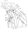
Fig. 2 is a left lateral view illustrating the front portion of the scooter type vehicle according to the present invention. The scooter type vehicle 80 includes the steeringhandlebar 41 steered by a rider; a radiator 49 (the radiator unit 49) disposed under thefront seat 33 or a seat 81 on which the rider sits and adapted to cool the cooling water of the engine; astep floor 82 which is disposed between the steeringhandlebar 41 and the seat 81 and on which the rider's feet are placed; and theinner cover 59 disposed forward of thestep floor 82. - The
inner cover 59 has anupper portion 84t protruding toward a rider and including a stuff box portion 83 (a stuff box 83) and serves to cover the feet of the rider sitting on the seat 81. In the following description theinner cover 59 is called theleg shield 84. -
Fig. 3 is a cross-sectional view taking along line 3-3 ofFig. 2 . Thestep floor 82 includes a pair offoot placing portions lateral wall portions foot placing portions - With reference to
Figs. 2 and3 , theleg shield 84 is disposed above the left and rightlateral wall portions leg shield 84 is provided with an openingportion 93 serving as a feed-water port for theradiator 49. The openingportion 93 is covered by acover member 91 extending along atunnel portion 88 in the back and forth direction of the vehicle body. The openingportion 93 is joined to one of the lateral wall portions of thetunnel portion 88 and disposed below thestuff box portion 83. - In other words, the opening
portion 93 is provided in thelateral wall 92 of theleg shield 84 at a portion joined to thelateral wall portions stuff box portion 83. In addition, a feed-water nozzle 95 is disposed to face the openingportion 93. The feed-water nozzle 95 is connected via the feed-water pipe 94 to theradiator 49 and is adapted to feed cooling water thereto. - Of the left and right sides of the vehicle, the opening
portion 93 is disposed on a side opposite to the side where the feed-water pipe 94 is connected to theradiator 49. - Alternatively, an
opening portion 93B may be disposed on the side where a feed-water pipe 94B is connected to theradiator 49 as shown with imaginary lines, whereby the length of the feed-water pipe 94B can further be reduced. - A
lid member 96 is detachably attached to the feed-water nozzle 95 in such a manner that thelid member 96 can be taken out to the outside of thecover member 91 through the openingportion 93. - Since the
lid member 96 is provided so that it can be taken out to the outside of thecover member 91 through the openingportion 93, thelid member 96 can be taken out to the outside of thecover member 91 when water is fed. Thus, operation for feeding water into theradiator 49 can easily be carried out. -
Fig. 4 is a lateral view of the leg shield attached to the front portion of the vehicle according to the present invention. Theleg shield 84 includes leg-coveringportions 98 provided right and left to cover the legs of the rider;lateral walls 92 provided rearward of the leg-coveringportions 98; and thestuff box portion 83 formed upward of and continuously with the right leg-coveringportion 98. Thelateral wall 92 is formed with the openingportion 93. -
Fig. 5 is a cross-sectional view taken along line 5-5 ofFig. 4 . The openingportion 93 bored in thelateral wall 92 is covered by thecover member 91 extending along the tunnel portion (seereference numeral 88 ofFig. 3 ) in the back and forth direction of the vehicle body. - An engaging hole 99 is formed forward of the opening
portion 93 and an engagingportion 101 of thecover member 91 is configured to engage the engaging hole 99. - The opening
portion 93 is covered by thecover member 91 extending along thetunnel portion 88 in the back and forth direction of the vehicle body; therefore, it can be suppressed that the external appearance of the vehicle is degraded by the openingportion 93. -
Fig. 6 is a cross-sectional view taken along line 6-6 ofFig. 2 , illustrating a support structure for thecover member 91. Thelateral wall portion 86L of thestep floor 82 is provided with a receivingportion 102 formed in an approximately U-shape in cross-section. Thecover member 91 is attached to the vehicle body side by inserting and fitting alower end portion 91 b of thecover member 91 into the receivingmember 102. Incidentally, since the right-handlateral wall portion 86R has the same structure as that of the lefthandlateral wall portion 86L, the description thereof is omitted. -
Fig. 7 includes views for assistance in explaining a cover member engaging portion with the vehicle body side and the operation thereof according to the present invention. - Referring to
Fig. 7(a) , thecover member 91 is provided at the lower side portion thereof with a first, a second and a thirdengaging claw engaging groove step floor 82 of the vehicle body. Similarly, thecover member 91 is provided at the upper side portion thereof with a first, a second and a thirdengaging projection holes lateral wall 92 of theleg shield 84. - The
cover member 91 is attached to thelateral wall 92 of theleg shield 84 by inserting the first, second, thirdengaging claws engaging grooves engaging portion 101 to the engaging hole (reference numeral 99 inFig. 5 ). -
Fig. 7(b) is an enlarged view of a b-portion ofFig. 7(a) , illustrating the configuration of the first through thirdengaging projections 105a through 105c provided on thecover member 91. The first and thirdengaging projections engaging projection 105b. It is facilitated to identify the up-and-down direction of thecover member 91 to be attached to thelateral wall 92. Thus, the attachment operation of thecover member 91 can easily be carried out. -
Fig. 8 is a view for assistance in explaining the configuration of the peripheral portion of the radiator of the scooter type vehicle according to the present invention. - The fuel tank (
reference numeral 43 ofFig. 1 ) is disposed rearward of theradiator 49. Afuel tank cover 111 is disposed to cover thefuel tank 43. - The
fuel tank cover 111 is a member that is disposed between theradiator 49 and thefuel tank 43 and near thefuel tank 43 and covers thefuel tank 43 from the front thereof. - A
hose 113 is arranged to extend between the feed-water nozzle 95 and areservoir tank 112 and connect them and supported by thefuel tank cover 111. Thereservoir tank 112 is adapted to store cooling water for the engine (reference numeral 42 ofFig. 1 ) mounted on the vehicle body. In addition, thereservoir tank 112 is disposed on a side different from the side of the feed-water nozzle 95. - The
hose 113 connecting the feed-water nozzle 95 with the reservoir tank is disposed rearward of theradiator 49 and supported by thefuel tank cover 111. Therefore, a dedicated support member can be eliminated. Since the dedicated support member is eliminated, an increase in number of component parts can be suppressed. -
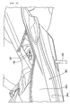
Fig. 9 is a view for assistance in explaining a support structure for the hose provided for the fuel tank cover.Fig. 10 is a perspective view of a vehicle body front portion, illustrating the layout of the hose connecting the reservoir tank with the feed-water nozzle 95 according to the present invention. A description is made below with reference toFigs. 9 and10 . - The
fuel tank cover 111 is provided for the fuel tank (reference numeral 43 inFig. 1 ) and thehose 113 is provided on thefuel tank cover 111 so as to be supportable at a preferable position thereon. This makes it possible to increase the flexibility of layout of thehose 113 extending between the feed-water nozzle 95 and thereservoir tank 112. - The
hose 113 is supported by thefuel tank cover 111 at a plurality of positions in a vehicle-width direction. Among a plurality ofsupport portions 115a through 115d supporting thehose 113, thesupport portion 115d close to the feed-water nozzle 95 is offset downward from the other supportingportions 115a to 115c by a distance of "p", thus increasing the curvature radius R of thehose 113. - The increased curvature radius R of the
hose 113 can make it difficult to apply a strong force to thehose 113, thereby enhancing the durability of thehose 113. - Incidentally, the
support portion 115d close to the feed-water nozzle 95 may be offset upward from theother support portions 115a to 115c. - A description is next made of the operation of the scooter type vehicle provided with the radiator described above.
- Referring again to
Fig. 2 , thelateral wall 92 of theleg shield 84 which is a portion joined to thelateral wall portions step floor 82 is provided with the openingportion 93 that the feed-water nozzle 95 of theradiator 49 faces. - Since the feed-
water nozzle 95 of theradiator 49 is made to face the openingportion 93, it is possible to feed water without removal of thestuff box portion 83. Since it is possible to feed water into theradiator 49 without removal of thestuff box portion 83, maintenance performance for theradiator 49 can be enhanced. - In addition, since the
lateral wall 92 is provided with the openingportion 93, it is not necessary to extend the feed-water pipe 94 for theradiator 49 to the position of thestuff box portion 83 provided at the upper portion of theleg shield 84. That is to say, since it is not necessary to extend the feed-water pipe 94 for theradiator 49 to the upper portion of theleg shield 84, the length of the feed-water pipe 94 can be reduced while effectively utilizing the dead space of the vehicle. - With reference to
Figs. 1 to 3 , the scooter type vehicle 80 is provided with the side stand 66 and the openingportion 93 is disposed on the side where the side stand 66 is provided. If water is fed with the vehicle inclined by use of theside stand 66, a rider can look at the feed-water nozzle 95 from the oblique upside. This makes it easy to visibly recognize the feed-water nozzle 95, further enhancing the maintenance performance for theradiator 49. -
Fig. 11 illustrates another embodiment corresponding to the embodiment shown inFig. 2 . A description is made of a case where anopening portion 93C is provided at atunnel portion 88 of astep floor 82 provided rearward of aleg shield 84. - The
step floor 82 includes a pair offoot placing portions tunnel portion 88. Thetunnel portion 88 is formed, to protrude upward, by left and rightlateral wall portions foot placing portions upper wall 87 joining together the left and rightlateral wall portions - The left
lateral wall portion 86L is provided with theopening portion 93C as the feed-water nozzle 95 for theradiator 49. Theopening portion 93C is covered by acover member 91 extending in the back and forth direction of the vehicle body along thelateral wall 92 of theleg shield 84 joined to thetunnel portion 88. - The
opening portion 93C is provided at thelateral wall 92 of theleg shield 84 which is a portion joined to thelateral wall portions stuff box portion 83. A feed-water nozzle 95C which is connected to theradiator 49 via a feed-water pipe 94C and adapted to feed cooling water is made to face theopening portion 93C. - The
opening portion 93C is disposed on a side opposite to the side where the feed-water pipe 94C is connected to theradiator 49, of the left and right sides of the vehicle. - Alternatively, an
opening portion 93D may be disposed on the side where a feed-water pipe 94D is connected to theradiator 49, as shown with imaginary lines, whereby the length of the feed-water pipe 94D can further be reduced. - A
lid member 96C is detachably attached to the feed-water nozzle 95C in such a manner that thelid member 96C and feed-water nozzle 95C can be taken out to the outside of thecover member 91 through theopening portion 93C. Specifically, since the feed-water pipe 94C is made of hard rubber, it can be taken out to the outside of thecover member 91 during maintenance. - Since the feed-
water nozzle 95C and thelid member 96C are provided so that they can be taken out to the outside of thecover member 91 through theopening portion 93C, theopening portion 93C can visibly be recognized with ease, so that operation for feeding water into theradiator 49 can easily be carried out. -
Fig. 12 is a perspective view for assistance in explaining the fact that maintenance for the engine can be enabled by removing the cover member from the vehicle body side. In the figure,reference numeral 116 denotes an ignition plug detachably attached to theengine 42. - The cover member (
reference numeral 91 inFig. 2 ) detached from the vehicle body side also serves as a maintenance lid for theengine 42; therefore, a dedicated maintenance lid is eliminated. Since the dedicated maintenance lid is eliminated, an increase in number of component parts can be suppressed. - Incidentally, in claim 1, the opening portion may not be disposed on the side where the feed-water pipe is connected to the radiator, of the left and right sides of the vehicle. For example, the opening portion may be disposed on a side opposite to the side where the feed-water pipe is connected to the radiator, of the left and right sides of the vehicle.
- In addition, the opening portion may not be disposed on the side where the side stand is provided. For example, the opening portion may be disposed on a side opposite to the side where the side stand is provided.
- The present invention is suitable for a scooter type vehicle provided with a radiator for cooling the cooling water of a water-cooled engine.
- The invention is directed to a scooter type vehicle that reduces the length of a feed-water pipe and to enhance the maintenance performance for a radiator.
- In a scooter type vehicle 80 including a
steering handlebar 41, aradiator 49 disposed under a seat 81, astep floor 82 disposed between the steeringhandlebar 41 and the seat 81, and aleg shield 84 disposed forward of thestep floor 82, having anupper portion 84t protruding toward a rider side and including astuff box portion 83 and shielding the legs of the rider, theleg shield 84 is provided with an openingportion 93 as a feed-water port for theradiator 49 and the openingportion 93 is covered by acover member 91 extending along thetunnel portion 88 in the back and forth direction of a vehicle body.
Claims (8)
- A scooter type vehicle (80) comprising:a radiator (49) disposed below and between a steering handlebar (41) steered by a rider and a seat (81) on which the rider sits and adapted to cool the cooling water of a water-cooled engine (42);step floors (82) which are disposed between the steering handlebar (41) and the seat (81) and on which the rider's feet are placed; anda leg shield (84) disposed forward of the step floors (82), having an upper portion protruding toward the rider side and including a stuff box (83), and shielding the legs of the rider sitting on the seat (81);wherein the step floors (82) include a pair of left and right foot placing portion (85L, 85R) on which the rider's feet are placed, and a tunnel portion (88) formed to protrude upward by left and right lateral portions joined respectively to the left and right foot placing portion (85L, 85R) and an upper wall (87) connecting the left and right lateral wall portions (86L, 86R); and
wherein the lateral wall portion (86L, 86R) or a portion joined to the lateral wall portion (86L, 86R) and below the stuff box (83) is provided with an opening portion (93, 93B, 93C, 93D) and a feed-water nozzle (95, 95B, 95C, 95D) connected to the radiator (49) via a feed-water pipe (94, 94B, 94C, 94D) and adapted to feed water to the radiator (49) is disposed to face the opening portion (93, 93B, 93C, 93D). - The scooter type vehicle (80) according to claim 1, wherein the opening portion (93, 93B, 93C, 93D) is covered by a cover member (91) extending along the tunnel portion (88) in the back and forth direction of a vehicle body.
- The scooter type vehicle (80) according to claim 1 or 2, wherein a lid member (96, 96B, 96C, 96D) is detachably attached to the feed-water nozzle (95, 95B, 95C, 95D) and can be taken out to the outside of the cover member (91) through the opening portion (93, 93B, 93C, 93D).
- The scooter type vehicle (80) according to claim 1, 2 or 3, wherein the opening portion (93, 93B, 93C, 93D) is disposed, of the left and right sides of the vehicle, on a side where the feed-water pipe (94, 94B, 94C, 94D) is connected to the radiator (49).
- The scooter type vehicle (80) according to any one of claims 1 through 4, further comprising a side stand (66); wherein the opening portion (93, 93B, 93C, 93D) is disposed on a side where the side stand (66) is provided.
- The scooter type vehicle (80) according to any one of claims 1 through 5, wherein a fuel tank (43) is provided rearward of the radiator (49), a fuel tank cover (111) is provided for the fuel tank (43), a hose (113) is provided to connect the feed-water nozzle (95, 95B, 95C, 95D) with a reservoir tank (112) for storing cooling water for an engine mounted on the vehicle body, and the hose (113) is supported by the fuel tank cover (111).
- The scooter type vehicle (80) according to claim 6, wherein the reservoir tank (112) is disposed on a side different from the side of the feed-water nozzle (95, 95B, 95C, 95D), the hose (113) is supported by the fuel tank cover (111) at a plurality of positions in a vehicle-width direction and a curvature radius of the hose (113) is increased by allowing a support portion close to the feed-water portion (115d) to be offset upward or downward from the other support portions (115a-115c).
- The scooter type vehicle (80) according to claim 2, wherein the cover member (91) also serves as a maintenance lid for the engine.
Applications Claiming Priority (1)
| Application Number | Priority Date | Filing Date | Title |
|---|---|---|---|
| JP2007049685A JP4991349B2 (en) | 2007-02-28 | 2007-02-28 | Scooter type vehicle |
Publications (2)
| Publication Number | Publication Date |
|---|---|
| EP1964758A1 true EP1964758A1 (en) | 2008-09-03 |
| EP1964758B1 EP1964758B1 (en) | 2009-07-01 |
Family
ID=39327232
Family Applications (1)
| Application Number | Title | Priority Date | Filing Date |
|---|---|---|---|
| EP08001432A Not-in-force EP1964758B1 (en) | 2007-02-28 | 2008-01-25 | Scooter type vehicle |
Country Status (6)
| Country | Link |
|---|---|
| US (1) | US7845446B2 (en) |
| EP (1) | EP1964758B1 (en) |
| JP (1) | JP4991349B2 (en) |
| CN (1) | CN101254807B (en) |
| DE (1) | DE602008000034D1 (en) |
| ES (1) | ES2327798T3 (en) |
Cited By (1)
| Publication number | Priority date | Publication date | Assignee | Title |
|---|---|---|---|---|
| CN105501342A (en) * | 2014-10-10 | 2016-04-20 | 本田技研工业株式会社 | Saddle-riding type vehicle |
Families Citing this family (10)
| Publication number | Priority date | Publication date | Assignee | Title |
|---|---|---|---|---|
| JP2009255627A (en) * | 2008-04-14 | 2009-11-05 | Yamaha Motor Co Ltd | Saddle-riding type vehicle |
| JP5323514B2 (en) * | 2009-01-29 | 2013-10-23 | 本田技研工業株式会社 | Radiator mounting structure for saddle-ride type vehicles |
| JP5629245B2 (en) * | 2011-07-31 | 2014-11-19 | 本田技研工業株式会社 | Vehicle with step floor |
| JP5969232B2 (en) * | 2012-03-22 | 2016-08-17 | 本田技研工業株式会社 | Radiator hose layout structure for saddle-ride type vehicles |
| JP5893459B2 (en) * | 2012-03-22 | 2016-03-23 | 本田技研工業株式会社 | Fuel tank and radiator arrangement structure for saddle-ride type vehicles |
| JP5894826B2 (en) * | 2012-03-22 | 2016-03-30 | 本田技研工業株式会社 | Lift-up support structure for saddle-ride type vehicles |
| JP5925547B2 (en) * | 2012-03-22 | 2016-05-25 | 本田技研工業株式会社 | Wind guide structure for saddle-ride type vehicles |
| JP5806643B2 (en) | 2012-05-31 | 2015-11-10 | 本田技研工業株式会社 | Body cover structure for saddle-ride type vehicles |
| KR101845643B1 (en) * | 2013-07-31 | 2018-04-04 | 혼다 기켄 고교 가부시키가이샤 | Motorcycle body cover structure |
| CN113306661B (en) * | 2020-02-26 | 2022-08-16 | 雅马哈发动机株式会社 | Saddle-ride type vehicle |
Citations (5)
| Publication number | Priority date | Publication date | Assignee | Title |
|---|---|---|---|---|
| JPH08127377A (en) * | 1994-10-31 | 1996-05-21 | Suzuki Motor Corp | Radiator arrangement structure of scooter type vehicle |
| EP0755819A1 (en) * | 1995-06-29 | 1997-01-29 | Yamaha Hatsudoki Kabushiki Kaisha | Motorcycle in particular of the scooter type |
| JP2001063657A (en) | 1999-08-31 | 2001-03-13 | Yamaha Motor Co Ltd | Motorcycle storage device |
| EP1275830A2 (en) * | 2001-07-09 | 2003-01-15 | Yamaha Hatsudoki Kabushiki Kaisha | Scooter type motorcycle |
| US20050155804A1 (en) * | 2003-10-10 | 2005-07-21 | Honda Motor Co., Ltd. | Article storage structure for scooter-type vehicle |
Family Cites Families (10)
| Publication number | Priority date | Publication date | Assignee | Title |
|---|---|---|---|---|
| JPS5948280A (en) * | 1982-09-11 | 1984-03-19 | 本田技研工業株式会社 | Engine cooling systems for motorcycles, etc. |
| JPS6028716B2 (en) * | 1982-09-11 | 1985-07-06 | 本田技研工業株式会社 | Engine cooling systems for motorcycles, etc. |
| JPS6067224A (en) * | 1983-09-26 | 1985-04-17 | Honda Motor Co Ltd | Motor-cycle |
| JPH065991Y2 (en) * | 1985-08-07 | 1994-02-16 | 本田技研工業株式会社 | Arrangement structure of radiator reserve tank |
| JP3423487B2 (en) * | 1995-06-29 | 2003-07-07 | ヤマハ発動機株式会社 | Radiator arrangement structure of scooter type motorcycle |
| JP3489805B2 (en) * | 1997-01-21 | 2004-01-26 | 本田技研工業株式会社 | Motorcycle |
| JP2006240315A (en) * | 2003-05-20 | 2006-09-14 | Yamaha Motor Co Ltd | Saddle riding vehicle |
| JP4252876B2 (en) * | 2003-10-10 | 2009-04-08 | 本田技研工業株式会社 | Motorcycle |
| JP4451140B2 (en) * | 2004-01-20 | 2010-04-14 | 本田技研工業株式会社 | Arrangement structure for unlocking operation member in vehicle |
| JP4296144B2 (en) * | 2004-09-29 | 2009-07-15 | 本田技研工業株式会社 | Fuel cell motorcycle |
-
2007
- 2007-02-28 JP JP2007049685A patent/JP4991349B2/en not_active Expired - Fee Related
-
2008
- 2008-01-25 ES ES08001432T patent/ES2327798T3/en active Active
- 2008-01-25 EP EP08001432A patent/EP1964758B1/en not_active Not-in-force
- 2008-01-25 DE DE602008000034T patent/DE602008000034D1/en active Active
- 2008-02-25 US US12/036,871 patent/US7845446B2/en not_active Expired - Fee Related
- 2008-02-25 CN CN2008100813406A patent/CN101254807B/en not_active Expired - Fee Related
Patent Citations (5)
| Publication number | Priority date | Publication date | Assignee | Title |
|---|---|---|---|---|
| JPH08127377A (en) * | 1994-10-31 | 1996-05-21 | Suzuki Motor Corp | Radiator arrangement structure of scooter type vehicle |
| EP0755819A1 (en) * | 1995-06-29 | 1997-01-29 | Yamaha Hatsudoki Kabushiki Kaisha | Motorcycle in particular of the scooter type |
| JP2001063657A (en) | 1999-08-31 | 2001-03-13 | Yamaha Motor Co Ltd | Motorcycle storage device |
| EP1275830A2 (en) * | 2001-07-09 | 2003-01-15 | Yamaha Hatsudoki Kabushiki Kaisha | Scooter type motorcycle |
| US20050155804A1 (en) * | 2003-10-10 | 2005-07-21 | Honda Motor Co., Ltd. | Article storage structure for scooter-type vehicle |
Cited By (2)
| Publication number | Priority date | Publication date | Assignee | Title |
|---|---|---|---|---|
| CN105501342A (en) * | 2014-10-10 | 2016-04-20 | 本田技研工业株式会社 | Saddle-riding type vehicle |
| CN105501342B (en) * | 2014-10-10 | 2019-01-18 | 本田技研工业株式会社 | Saddle-riding type vehicle |
Also Published As
| Publication number | Publication date |
|---|---|
| DE602008000034D1 (en) | 2009-08-13 |
| CN101254807B (en) | 2010-07-21 |
| US7845446B2 (en) | 2010-12-07 |
| ES2327798T3 (en) | 2009-11-03 |
| JP4991349B2 (en) | 2012-08-01 |
| CN101254807A (en) | 2008-09-03 |
| EP1964758B1 (en) | 2009-07-01 |
| JP2008213520A (en) | 2008-09-18 |
| US20080202836A1 (en) | 2008-08-28 |
Similar Documents
| Publication | Publication Date | Title |
|---|---|---|
| EP1964758B1 (en) | Scooter type vehicle | |
| JP5362694B2 (en) | Saddle riding vehicle | |
| EP2848507A1 (en) | Saddle type vehicle | |
| JP5926653B2 (en) | Storage structure of saddle-ride type vehicle | |
| EP1245442B1 (en) | Vehicle rear structure | |
| JP2010013065A (en) | Vehicle body cover structure for motorcycle | |
| US20150166137A1 (en) | Tank cover structure for motorcycle | |
| JP5289883B2 (en) | Saddle riding vehicle | |
| JP4145370B2 (en) | Engine cooling structure for scooter type vehicles | |
| CN101058330B (en) | motorcycle | |
| JP2010247816A (en) | Motorcycle | |
| EP2824023B1 (en) | Motorcycle | |
| JP3442742B2 (en) | Cooling device for rough terrain vehicle | |
| US7735892B2 (en) | Front portion structure of vehicle | |
| US9581073B2 (en) | Radiator structure for two-wheeled vehicle | |
| JP2008050006A (en) | Heat shield structure of scooter type vehicle fuel tank | |
| JP3504098B2 (en) | Windshield for scooter type vehicle | |
| JP2005088798A (en) | Carrier device | |
| CN216102547U (en) | Saddle-ride type vehicle | |
| CN110155225A (en) | saddle ride vehicle | |
| JP2534228B2 (en) | Air cleaner device for saddle type vehicle | |
| JP4199087B2 (en) | vehicle | |
| JP3041820B2 (en) | Motorcycle and tricycle handle covers | |
| KR20080028273A (en) | Cooling structure for continous variable transmission of motorcycle | |
| JP5010942B2 (en) | Scooter type vehicle |
Legal Events
| Date | Code | Title | Description |
|---|---|---|---|
| PUAI | Public reference made under article 153(3) epc to a published international application that has entered the european phase |
Free format text: ORIGINAL CODE: 0009012 |
|
| 17P | Request for examination filed |
Effective date: 20080125 |
|
| AK | Designated contracting states |
Kind code of ref document: A1 Designated state(s): AT BE BG CH CY CZ DE DK EE ES FI FR GB GR HR HU IE IS IT LI LT LU LV MC MT NL NO PL PT RO SE SI SK TR |
|
| AX | Request for extension of the european patent |
Extension state: AL BA MK RS |
|
| GRAP | Despatch of communication of intention to grant a patent |
Free format text: ORIGINAL CODE: EPIDOSNIGR1 |
|
| GRAS | Grant fee paid |
Free format text: ORIGINAL CODE: EPIDOSNIGR3 |
|
| RIN1 | Information on inventor provided before grant (corrected) |
Inventor name: ENJO, SADAMICHIC/O HONDA R&D CO., LTD. Inventor name: ATSUCHI, MICHIOC/O HONDA R&D CO., LTD. |
|
| AKX | Designation fees paid |
Designated state(s): DE ES IT |
|
| GRAA | (expected) grant |
Free format text: ORIGINAL CODE: 0009210 |
|
| RIC1 | Information provided on ipc code assigned before grant |
Ipc: F02B 61/02 20060101ALI20090519BHEP Ipc: F01P 3/18 20060101ALI20090519BHEP Ipc: B62J 17/00 20060101ALI20090519BHEP Ipc: B62J 99/00 20090101AFI20090519BHEP |
|
| RIN1 | Information on inventor provided before grant (corrected) |
Inventor name: ENJO, SADAMICHIC/O HONDA R&D CO., LTD. Inventor name: ATSUCHI, MICHIOC/O HONDA R&D CO., LTD. |
|
| AK | Designated contracting states |
Kind code of ref document: B1 Designated state(s): DE ES IT |
|
| REF | Corresponds to: |
Ref document number: 602008000034 Country of ref document: DE Date of ref document: 20090813 Kind code of ref document: P |
|
| REG | Reference to a national code |
Ref country code: ES Ref legal event code: FG2A Ref document number: 2327798 Country of ref document: ES Kind code of ref document: T3 |
|
| PLBE | No opposition filed within time limit |
Free format text: ORIGINAL CODE: 0009261 |
|
| STAA | Information on the status of an ep patent application or granted ep patent |
Free format text: STATUS: NO OPPOSITION FILED WITHIN TIME LIMIT |
|
| 26N | No opposition filed |
Effective date: 20100406 |
|
| REG | Reference to a national code |
Ref country code: DE Ref legal event code: R084 Ref document number: 602008000034 Country of ref document: DE |
|
| PGFP | Annual fee paid to national office [announced via postgrant information from national office to epo] |
Ref country code: ES Payment date: 20180201 Year of fee payment: 11 Ref country code: DE Payment date: 20180110 Year of fee payment: 11 |
|
| REG | Reference to a national code |
Ref country code: DE Ref legal event code: R119 Ref document number: 602008000034 Country of ref document: DE |
|
| PG25 | Lapsed in a contracting state [announced via postgrant information from national office to epo] |
Ref country code: DE Free format text: LAPSE BECAUSE OF NON-PAYMENT OF DUE FEES Effective date: 20190801 |
|
| REG | Reference to a national code |
Ref country code: ES Ref legal event code: FD2A Effective date: 20200310 |
|
| PG25 | Lapsed in a contracting state [announced via postgrant information from national office to epo] |
Ref country code: ES Free format text: LAPSE BECAUSE OF NON-PAYMENT OF DUE FEES Effective date: 20190126 |
|
| PGFP | Annual fee paid to national office [announced via postgrant information from national office to epo] |
Ref country code: IT Payment date: 20211213 Year of fee payment: 15 |
|
| PG25 | Lapsed in a contracting state [announced via postgrant information from national office to epo] |
Ref country code: IT Free format text: LAPSE BECAUSE OF NON-PAYMENT OF DUE FEES Effective date: 20230125 |