EP1964736B1 - Systeme und Verfahren zur Bestimmung eines Parameters in Zusammenhang mit dem Kontakt zwischen Reifen und Straße und/oder dem Verhältnis zwischen einem Rad und einer Fahrzeugbewegung - Google Patents
Systeme und Verfahren zur Bestimmung eines Parameters in Zusammenhang mit dem Kontakt zwischen Reifen und Straße und/oder dem Verhältnis zwischen einem Rad und einer Fahrzeugbewegung Download PDFInfo
- Publication number
- EP1964736B1 EP1964736B1 EP07004274A EP07004274A EP1964736B1 EP 1964736 B1 EP1964736 B1 EP 1964736B1 EP 07004274 A EP07004274 A EP 07004274A EP 07004274 A EP07004274 A EP 07004274A EP 1964736 B1 EP1964736 B1 EP 1964736B1
- Authority
- EP
- European Patent Office
- Prior art keywords
- tire
- slip
- force
- friction
- data
- Prior art date
- Legal status (The legal status is an assumption and is not a legal conclusion. Google has not performed a legal analysis and makes no representation as to the accuracy of the status listed.)
- Active
Links
- 238000000034 method Methods 0.000 title claims abstract description 125
- 230000033001 locomotion Effects 0.000 title claims abstract description 45
- 238000001914 filtration Methods 0.000 claims abstract description 30
- 230000008859 change Effects 0.000 claims description 16
- 238000005096 rolling process Methods 0.000 claims description 13
- 238000012935 Averaging Methods 0.000 claims description 4
- 238000005457 optimization Methods 0.000 description 20
- 230000015654 memory Effects 0.000 description 18
- 230000006870 function Effects 0.000 description 17
- 238000005259 measurement Methods 0.000 description 15
- 238000012546 transfer Methods 0.000 description 13
- 230000001133 acceleration Effects 0.000 description 12
- 230000006399 behavior Effects 0.000 description 8
- 230000001419 dependent effect Effects 0.000 description 7
- 238000001514 detection method Methods 0.000 description 6
- 238000013459 approach Methods 0.000 description 5
- 230000000694 effects Effects 0.000 description 5
- 239000011159 matrix material Substances 0.000 description 5
- 238000012545 processing Methods 0.000 description 5
- 239000013598 vector Substances 0.000 description 5
- 230000005284 excitation Effects 0.000 description 4
- 230000035945 sensitivity Effects 0.000 description 4
- 238000004364 calculation method Methods 0.000 description 3
- 238000012937 correction Methods 0.000 description 3
- 238000009826 distribution Methods 0.000 description 3
- 238000009472 formulation Methods 0.000 description 3
- 239000000203 mixture Substances 0.000 description 3
- 238000000926 separation method Methods 0.000 description 3
- 238000003860 storage Methods 0.000 description 3
- PXFBZOLANLWPMH-UHFFFAOYSA-N 16-Epiaffinine Natural products C1C(C2=CC=CC=C2N2)=C2C(=O)CC2C(=CC)CN(C)C1C2CO PXFBZOLANLWPMH-UHFFFAOYSA-N 0.000 description 2
- 239000000853 adhesive Substances 0.000 description 2
- 230000001070 adhesive effect Effects 0.000 description 2
- 230000008901 benefit Effects 0.000 description 2
- 230000005484 gravity Effects 0.000 description 2
- 230000003068 static effect Effects 0.000 description 2
- 230000006978 adaptation Effects 0.000 description 1
- 230000002730 additional effect Effects 0.000 description 1
- 238000004458 analytical method Methods 0.000 description 1
- 239000010426 asphalt Substances 0.000 description 1
- 238000000418 atomic force spectrum Methods 0.000 description 1
- 230000005540 biological transmission Effects 0.000 description 1
- 238000011161 development Methods 0.000 description 1
- 230000018109 developmental process Effects 0.000 description 1
- 230000004069 differentiation Effects 0.000 description 1
- 238000012417 linear regression Methods 0.000 description 1
- 230000007246 mechanism Effects 0.000 description 1
- 238000005192 partition Methods 0.000 description 1
- 230000000737 periodic effect Effects 0.000 description 1
- 230000002688 persistence Effects 0.000 description 1
- 230000002085 persistent effect Effects 0.000 description 1
- 238000012805 post-processing Methods 0.000 description 1
- 230000008569 process Effects 0.000 description 1
- 238000005070 sampling Methods 0.000 description 1
- 238000012360 testing method Methods 0.000 description 1
- 238000005303 weighing Methods 0.000 description 1
Images


Classifications
-
- B—PERFORMING OPERATIONS; TRANSPORTING
- B60—VEHICLES IN GENERAL
- B60T—VEHICLE BRAKE CONTROL SYSTEMS OR PARTS THEREOF; BRAKE CONTROL SYSTEMS OR PARTS THEREOF, IN GENERAL; ARRANGEMENT OF BRAKING ELEMENTS ON VEHICLES IN GENERAL; PORTABLE DEVICES FOR PREVENTING UNWANTED MOVEMENT OF VEHICLES; VEHICLE MODIFICATIONS TO FACILITATE COOLING OF BRAKES
- B60T8/00—Arrangements for adjusting wheel-braking force to meet varying vehicular or ground-surface conditions, e.g. limiting or varying distribution of braking force
- B60T8/17—Using electrical or electronic regulation means to control braking
- B60T8/172—Determining control parameters used in the regulation, e.g. by calculations involving measured or detected parameters
-
- B—PERFORMING OPERATIONS; TRANSPORTING
- B60—VEHICLES IN GENERAL
- B60T—VEHICLE BRAKE CONTROL SYSTEMS OR PARTS THEREOF; BRAKE CONTROL SYSTEMS OR PARTS THEREOF, IN GENERAL; ARRANGEMENT OF BRAKING ELEMENTS ON VEHICLES IN GENERAL; PORTABLE DEVICES FOR PREVENTING UNWANTED MOVEMENT OF VEHICLES; VEHICLE MODIFICATIONS TO FACILITATE COOLING OF BRAKES
- B60T2210/00—Detection or estimation of road or environment conditions; Detection or estimation of road shapes
- B60T2210/10—Detection or estimation of road conditions
- B60T2210/12—Friction
Definitions
- the present invention refers to systems and to methods for determining at least one parameter relating to a tire-to-road contact and/or a relation between a wheel and a vehicle motion.
- the present invention refers to systems and to methods for determining the coefficient of friction between a tire and a road surface.
- the coefficient of friction is often a crucial parameter for the control of driver assistance systems, such as e.g. anti-skid systems (ABS), traction control systems (ASR) or electronic stability programs (ESP) in all kind of vehicles.
- driver assistance systems such as e.g. anti-skid systems (ABS), traction control systems (ASR) or electronic stability programs (ESP) in all kind of vehicles.
- ABS anti-skid systems
- ASR traction control systems
- ESP electronic stability programs
- parameters related to the vehicle motion may include all kind of motions, forces and torques acting on and in the vehicle as well as on the individual wheels.
- European patent EP 0 630 786 B1 suggests a method, in which the wheel speed, the rotational acceleration of the vehicle wheel and the braking pressure are determined, the wheel slip is calculated therefrom and from these values the coefficient of friction is determined by means of linear recursive estimation algorithms.
- a method for determining the coefficient of friction which uses different linear and non-linear tire models for calculating the tire forces, from which tire forces the coefficient of friction is estimated for each of a plurality of tires.
- the method as starting parameters uses e.g. the steering wheel angle, the lateral accelerations, the yaw rate, the wheel speed and estimates for the brake torque and the driving torque applied to the vehicle wheels.
- the longitudinal and lateral tire forces are estimated either from information provided by different vehicle sensors or by estimated surface coefficients of adhesion.
- One well-known approach is based on the estimation of the tire stiffness, which can be described by the inclination of the tire force relative to the tire slip at low slips. From the value of the inclination it is distinguished between different conditions of the road surface by using a linear tire model which assumes that the actual tire stiffness and the actual road condition are interrelated.
- the tire stiffness depends on many factors and a generic relation between the inclination and the exact coefficient of friction or other parameters relating to a tire-to-road contact and/or a relation between a wheel and a vehicle motion is therefore not possible to obtain. Even the surface detection is not always reliable due to the large variation of the tire stiffness invoked by other reasons. Thus, the use of the tire stiffness as an indicator for friction, other tire-dependent or other vehicle motion-dependent parameters is limited to certain, few real conditions. This is particular due to the fact that the parameters used for the algorithms in question can change quickly so that also the importance of each particular parameter changes as the value of, e.g. the slip changes. In some scenarios, the curvature of the relation between the tire force and the tire slip might be misinterpreted as a changed value of the tire stiffness for higher tire forces.
- the aim of the invention is to determine properties and characteristics of either the tire-to-road contact and/or of the motion behaviour of the vehicle for further processing in, e.g. vehicle assistance systems, from measurements of certain signals and thereby using a given physical model of the tire-to-road contact and/or the vehicle motion.
- the invention suggests new filtering dynamics to be used in such methods and systems, which further enhance the estimation procedures.
- a method for determining at least one parameter relating to a tire-to-road contact and/or a relation between a wheel and a vehicle motion, the method is comprising the steps of:
- This method is implemented by a system (the "data bin-system") for determining at least one parameter relating to a tire-to-road contact and/or a relation between a wheel and a vehicle motion, the system comprising
- control unit the control unit
- the signal can be single signals or a set of signals representing the different parameters within the system.
- the at least first parameter and the at least second parameter of the at least two parameters relating to the tire and/or the vehicle motion can be any parameters which are used and included in physical models to explain the behaviour of a tire in the tire-to-road contact and/or the vehicle motion, such as e.g. the tire stiffness, the tire slip, the tire force, etc..
- these parameters may be selected from all kind of motions, forces and torques which are acting on and in a vehicle during its movement.
- the physical models generally are representing the relationship which is defined by the at least two parameters relating to the tire and/or vehicle motion.
- the signal space defined by the at least two parameters is discretized into these so-called data bins, whereby the subsequent estimation is based on a set of these at least two parameters.
- the signal information contained in the data bins corresponds to a compact representation of a set of samples, e.g. in the form of average values, as will be explained below. Then, the collection of pairs of the values from all data bins constitutes a set of data pairs, which are sufficiently separated and used for the subsequent parameter estimation.
- intervals themselves will be defined by the set structure of the filter used depending on the desired signal quality.
- the "data bin-method" is either using the first parameter or the second parameter or, at the same time, both parameters to update the corresponding values in the data bins.
- the data bins used in the filtering estimation procedures as described above will contain more than two parameters relating to the tire and/or the vehicle motion. Further signal dimensions can be introduced leading to different types of data bins.
- the method determines to which data bin the pair containing said first parameter and the second parameter corresponding to said first parameter belongs to. In this selected data bin the values for both the first parameter and the second parameter are updated. In analogy, from the magnitude of the second parameter the method determines to which data bin the pair containing said second parameter and the first parameter corresponding to said second parameter belongs to. Accordingly, in this selected data bin the values for both the second parameter and the first parameter are updated.
- each sampling affects two separate data bins, one data bin which is derived from the signal of the first parameter and another data bin which is derived from the signal of the second parameter.
- a weighing routine is performed for each data bin to further enhance the reliability of the parameter estimation.
- the steps of updating the values of the two parameters in the data bins may include
- the system comprises means operative to average over the corresponding parameters and to assess the importance and/or the confidence of their values, respectively.
- the storage algorithm has to be equipped with a change detection feature that quickly erases the stored values in the data bins to adapt to any new condition.
- the defined change will be detected in at least one of the data bins.
- the first parameter is selected to be the tire force, preferably normalized tire force
- the second parameter is selected to be the tire slip.
- the such acquired contents of the data bins are then matched to said relationship, e.g. the behaviour of the physical model, by using optimization algorithms and then the at least one parameter to be determined is estimated from said relationship.
- the method further comprises the step of
- the curvature of the relation between the tire force and the tire slip can be determined in the tire/slip-data plane, and not, as in the methods and systems of the prior art, the slope or inclination of this relation which corresponds to the tire stiffness as an indicator of the friction in that the friction is derived from the deviation from linearity in the force-slip slope, as previously used in tire models.
- the physical model used for the tire behaviour can be also adapted to describe a relation between a self-aligning torque, which can be measured from the steering behaviour, as the first parameter and a lateral tire force as the second parameter.
- suitable optimization algorithms may include the methods of Recursive Least-Squares, Gauss-Newton or the so-called "grid-method", which according to the invention can be also used as an alternative to the afore-explained data bin-method for directly spatially dividing the parameter space, as will be described in more detail in the following.
- the method for determining at least one parameter relating to a tire-to-road contact and/or a relation between a wheel and a vehicle motion, the method comprising the steps of:
- the system which implements the above described "grid-method" according to the invention for determining at least one parameter relating to a tire-to-road contact and/or a relation between a wheel and a vehicle motion, comprises
- the "grid-method" enables a quick friction estimation, in that optimal values are chosen from a set of at least two parameters relating to the tire and/or vehicle motion when comparing the cost function during a certain amount of time. Accordingly, the method further comprises the steps of limiting the estimation filtering to a defined time frame.
- the at least first parameter is selected to be the coefficient of friction
- the at least second parameter is selected to be the tire stiffness
- both the "data bin-method” and the “grid-method” are further developed in that they further may comprise the steps of
- means are provided in which the value of the rolling radius of the tire is continuously corrected and updated.
- the above described different methods and their single steps will be performed in such a way that the different parameters will be determined for both the longitudinal direction and the lateral direction of the tire, and preferably individually for each tire of the vehicle, irrespective of the amount of wheels to be used by the vehicle to be controlled.
- the at least one parameter relating to the tire-to-road contact and/or the relation between a wheel and a vehicle motion to be determined is the coefficient of friction.
- the predefined tire model both used for the methods and the systems may be the physically based, so-called “Brush-tire model", which describes the effects of the frictional limitations in the contact patch for increasing slip.
- the "Brush-tire model” is well-known to those skilled in the art and explained in detail in the publication entitled “Tire Models for Use in Braking Applications " by Jacob Svendenius (Technical Report Licentiate thesis ISRN LUTFD2/TFRT - 3232 - SE, Lund Institute of Technology, Nov. 2003), which is hereby incorporated by reference herein.
- This tire model which in fact only uses three unknown parameters (lateral tire stiffness, longitudinal tire stiffness and tire/road friction coefficient) is used and adapted to specify the curvature of the force-slip relation on the one hand by using the discretization into predefined data bins according to the "data bin-method", or to specify the curvature of the tire stiffness-friction relation on the other hand by using predefined grid segments according to the "grid-method”, respectively.
- the states in the data bins which each represent the normalized tire force and the tire slip in the predefined tire model are used in the so-called cost function from which the optimal parameters for the tire stiffness and the coefficient of friction can be then calculated.
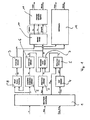
- Fig. 1 illustrates the general principle of a system and a method for determining or estimating the coefficient of friction according to the invention, whereby it has to be noted that steps 1 to 9 are per se known from the prior art and steps 10 to 11 and step 12, respectively, denote the additional effects according to the actual invention.
- the means to enable the single steps 1 to 11 or 1 to 12 as described can be implemented into a control unit or circuit arrangement, which can be used in vehicle assistance system, such as e. g. ABS or ESP.
- vehicle assistance system such as e. g. ABS or ESP.
- the input signals will be prepared for further processing.
- the input signals relate to the parameters which can be detected by suitable sensors arranged within the vehicle.
- vehicle-dependent parameters include the actual rotational speed of the wheel or tire w, whereby these rotational speeds can be determined for each individual wheels or tires of the vehicle, the rotational speed ⁇ eng which is provided by the engine to the wheels and the torque from the engine, T eng , as well as the actuating braking pressure p brk .
- step 2 from the rotational velocities w of the single wheels, the longitudinal acceleration a x can be determined.
- the according means of the control unit calculate the existing brake force per wheel from the pressure p brk applied by the brake actuator.
- Step 4 denotes the estimation of the gear as currently selected by the control unit in case of an automatic transmission or the detection of the gear as presently selected by the driver on basis of the signals w and ⁇ eng .
- step 5 means of the control unit enable the estimation of the driving force F x in longitudinal direction, from the actual values of the engine torques T eng and the existing gear.
- step 6 the vertical force F z is determined from the longitudinal acceleration a x .
- step 7 the normalized tire force f x can be determined from the vertical force F z and the driving force F x .
- step 10 to 11 denote the "data bin-method” or "data bin-system”
- step 12 denotes the "grid-method” or "grid-system”.
- Both methods can be used as alternatives to determine the actual values for the coefficient of friction and the tire stiffness.
- the grid estimator can be also used as the optimization procedures following the "data bin-method".
- step 10 a filtering processing is performed, in which the values for the actual normalized tire force f x and actual tire slip ⁇ x are stored in data bins. This method step will be explained in more detail below. Afterwards in step 11, the weighted contents of the data bins are used for the estimation of the desired parameters.
- step 12 a different filtering processing is performed, which will be explained in more detail below also.
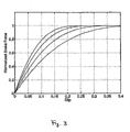
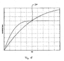
- Fig. 2 schematically illustrates one predefined tire model to be used in the methods and the systems according to the invention.
- the tire model shall be the so called "Brush tire model”.
- any other tire model can be used for the purpose of the invention.
- the "Brush tire model” is obtained by dividing the rubber volume in the contact region 13 of the road into small brush elements 14, regarded as elastic rectangular blades, or bristles, see Figure 2 .
- Each bristle 14 is assumed to deform independently in the longitudinal and lateral directions. Most essential in the model is the separation of the contact patch 13 into one adhesive area 15 and one sliding area 16, which are separated by the breakaway point x s .
- the bristles 14 adhere to the road surface and the deformation force is carried by static friction.
- the bristles 14 slide on the road surface under the influence of sliding friction.
- the deformation of the bristles 14 is denoted by ⁇ .
- the resulting force is independent of the deformations of the bristles 14.
- Equation (1) provides the relationship between the first parameter, namely the tire force ⁇ , and the second parameter, namely the tire slip ⁇ x , which pair of parameters are used for the data bins as will be explained further down below.
- the Brush tire model for varying parameters is exemplarily shown in Figure 3 , which illustrates the data plane as defined by said relationship between the tire force and the tire slip according to said model.
- the data so available will be further processed so as to provide a better accuracy of the estimation routines applied.
- Fig. 4a and Fig. 4b illustrate one example of applied estimation filtering procedures according to the invention: the concept of storing the data for the tire force and the tire slip in data bins which are defined in correspondence of specified intervals, as will be explained in the following.
- interval S i for the tire slip
- intervals F i for the tire force.
- the intervals can be evenly or unevenly distributed.
- One suitable distribution in the filtering would, for example, may be 15 intervals for the slip axis and up to 100 intervals for the force axis.
- the dots 17 represent samples of the values which have been stored in the respective data bins in these intervals S i and F i
- the staples 18 indicate the present number of value samples in each data bin in the intervals S i and F i , respectively.
- the crosses 19 denote the resulting estimates for the data bins per interval.
- a point wise approximation of g which is described by pairs (s' i , f' i ) and (s" i , f" i ) is constructed and then the estimation of the tire stiffness C x and the coefficient of friction ⁇ is enabled in that the cost as defined by: ⁇ i w i ⁇ ⁇ f i ⁇ - g s i ⁇ ⁇ C ⁇ x ⁇ ⁇ ⁇ 2 + ⁇ j j ⁇ ⁇ f j ⁇ - g s j ⁇ ⁇ C ⁇ x ⁇ ⁇ ⁇ 2 is minimized by the use of non-linear optimization methods, as this will be described further below.
- the memory segments formed as data bins are used to estimate an approximation of a monotone function g: x ⁇ y at discrete points along the ranges of x or y, from imperfect samples x ⁇ and ⁇ .
- x i - 1 ⁇ x ⁇ x i Y i y
- the crosses 19 in Figs. 4a and b indicate the resulting estimates for each of the corresponding data bins.
- the data bin estimation can be regarded as event based rather than time based, since the estimate in any particular data bin is updated only when measurement values fall within the corresponding range.
- the basic estimation in the filtering according to the invention is done by computing (x' i , y' i ) and (x" i , y" i ) as the recursive average of samples x ⁇ and ⁇ .
- a limited memory for each data bin is introduced by adding a sample-count limit N i and a sample count n i ⁇ [0,N i ] to the data bin tuples.
- a forgetting factor ⁇ i 1 - 1/n i is introduced such that the estimates will only depend on the last N i samples.
- x i ⁇ k ⁇ ⁇ i k ⁇ x i ⁇ ⁇ k - 1 + 1 - ⁇ i k ⁇ x ⁇ k , when x ⁇ k ⁇ X i x i ⁇ ⁇ k - 1 , otherwise
- the averaging routines in the computation for the data bins are generally used in order to reduce the effects of measurement noise.
- the estimates (x' i , y' i ), (x" i , y" i ) are formed by sums of the samples, they will approach a normal distribution as stated by the Central Limit Theorem CLT. In practice, it is unlikely that the CLT convergence will have any significant visible effects, since the sample-count limit N i will truncate the averaging sum.
- the filtering estimates procedures according to the invention further enable a confidence assessment for the respective values in the data bins, which provides measures of the content quality.
- a recursive variance estimate of the samples can be introduced.
- a freshness measure can be introduced to keep track of these data bins which contain the most recent information. Measures like this can be used to form weights w i to be used in the cost function (3) for further parameter estimation.
- the variance measure of the estimation filtering procedures can be used to eliminate outliers, for example by allowing only new samples that lie within a variance-dependent range from the current estimate. Care must be taken so that such mechanisms do not interfere with the change detection as described below.
- LP-filtering on the measurements can be performed in order to reduce the undesired effect of large noise.
- the data bin-concept is introduced to offer input data of a suitable format for the desired non-linear optimization algorithms. It is a method to store, in a compact form, information from different operating points with persistency over time. By this, it is easier to ensure sufficient excitation and the ability of observance for the desired parameter estimation. For example, it may prevent loss of the ability of observance when driving at constant slip for a long time. It also offers the possibility of convenient post-processing and confidence classification of data before delivered to the optimization algorithms. As a result, change detection and handling of outliers can be done intuitively. Additionally, the method reduces effects of measurement noise, which is particularly important for the slip.
- an "estimator” employing optimization algorithms is used, in order to continuously adapt the plurality of the estimated parameters of the "Brush tire model” to the actual tire force and the actual tire slip.
- the number of coupled observations in ⁇ is N.
- the Least-Squares method constitutes a robust method, which is limited to linear parameter relations and therefore used to detect the slope curvature at low slips where the third order term, from equation (1) can be neglected.
- the elements in the regressor vector ⁇ correspond to the parameters for the estimation in the vector ⁇ .
- the method generally is an offline-method, which means that a batch of data is necessary for the calculation of the parameters, which are supposed not to vary within the respective period.
- the input and output signals x, y are given by the values ⁇ x and f x derived and stored in the respective data bins.
- Gauss-Newton optimization method Another optimization to be used in connection with the invention is the Gauss-Newton optimization method, which is more computer demanding.
- the Gauss-Newton is able to catch non-linear behaviour and is used for a more accurate and reliable estimation when data points which are closer to the friction limit are available.
- the Gauss-Newton method is used as a substitute to the Least-Squares method when non-linear problems have to be solved.
- the general problem is to minimize the sum of errors according to equation (6).
- a non-linear problem can in most cases not be solved directly and the solution has to be found by iteration.
- the amount of iterations depends, e.g. on the properties of the function, the initial values of the parameters and the required accuracy on the estimates.
- the method works on a batch of data just as the method of Least-Squares.
- the benefit with the Gauss-Newton is that it catches the non-linearity in the "Brush tire model", which makes the result more accurate at slip values close to and above the limit slip.
- the so-called "grid-method” can be applied as optimization routines.
- this "grid-method" can be also used as an alternative to the data bin-based filtering in combination with an optimization routine.
- the estimator of the "grid-method" may be also used together with the data bin-filtering as a combined optimization approach.
- the "grid-method" provides an estimator which uses a predefined grid of the parameter space.
- the "grid-method" is able to provide the most stable performance, in particular as an alternative estimation technique.
- the grid estimator can be realized by introducing a multiple operating conditions dependence in the estimator, without introducing a slow convergence of the estimated parameters, in that multiple memories or memory sections in the estimated parameters are introduced.
- the smallest component of this equation represents the parameter set that is closest to the measurement for that specific measure formed by the filter G.
- the estimate will hence be a set of parameters belonging to the lattice P.
- one possibility is to use this approach in combination with the data bin filtering.
- the grid estimator is tuned by the filter G.
- This filter G forms the measure and hence defines the term closeness to the measurement ( ⁇ x , f ⁇ x ).
- the filter needs to be an integral.
- an integral would render the above-mentioned expression (15) to be remembering all past time, and a change in the conditions of the measurement, i.e. a change of the true friction and stiffness, would take some while to reveal itself.
- a forgetting factor will introduce a time horizon of the estimator and make the objective function finite.
- the tuning parameter T will then determine the noise sensitivity in the measurements and the ability to detect changes in the measurement. A small T will decrease the noise sensitivity and in addition decrease the sensitivity to changes of the real parameters.
- the convergence of the parameters is determined by the tuning parameter T, but not as in a conventional estimator. Given an initial condition of the states in the filter G, which is equal over the lattice, the convergence rate is independent of the tuning parameter (given that it is strictly positive, no noise is present in the data and that the data is generated from the model). An initial condition that is unequally distributed over the lattice will introduce a tuning parameter dependence of the convergence.
- the system and the methods can be further enhanced so as to enable more accurate results.
- the rolling radius R e affects the slip calculation and a deviation from its nominal value will cause a horizontal shift in the force-slip relationship as defined by the tire model, such that it does not cross the origin.
- R e and the deviation, ⁇ R has to be continuously updated by comparing the wheel speeds of each tire with a reference speed when no forces are transmitted by the tire. If the periods of free rolling are not sufficient the estimation can be complemented by adding one extra parameter, denoting the horizontal shift, in the optimization.
- the slip impact of the load transfer is a crucial parameter to be considered for the wheel radii correction routines.
- the radii of the tires are equal for all wheels when the vehicle is not exposed to any load transfer.
- ⁇ x ⁇ ⁇ ⁇ x 0 + 1 + ⁇ - 1
- ⁇ xo represents the slip with no load transfer, i.e. with all wheels having radius r 0 .
- the parameter k indicates the vertical tire stiffness, which is different for different tires. Given that the dependence in the rolling radius is linear, these differences can be compensated in that a fixed standard tire vertical stiffness is introduced.
- equation (19) and (20) in (17) one can compute the relative slip error given to the road condition, i.e. a value for ⁇ and a value for C x , and the acceleration a x as provided by the driver.
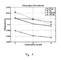
- Fig. 6 exemplarily illustrates the measured relation between the rolling radius of a winter tire and the vertical load on the tire depending on different ground conditions.
- the rolling radius depends on the vertical load acting on the individual tire. In many cases this dependency is small and can be almost neglected.
Claims (11)
- Verfahren zur Bestimmung eines Reibungskoeffizienten (µ) und/oder einer Reifensteifigkeit (Cx), wobei das Verfahren folgende Schritte aufweist:- Erfassung einer Vielzahl von Parametern (ω, pbrk, Teng, ωeng) bezüglich der Bewegung des Fahrzeugs,- Bestimmung eines Datenpaares (fx, σx) bestehend aus einer Reifenkraft (fx) und einem Reifenschlupf (σx) in einem Reifenkraft/Reifenschlupf-Raum aus der erfassten Vielzahl von Parametern (ω, pbrk, Teng, ωeng) bezüglich der Bewegung des Fahrzeugs,
gekennzeichnet durch- Segmentierung des Reifenkraft/Reifenschlupf-Raumes in Intervalle (Fi, Si), die für Werte der Reifenkraft (fx) und des Reifenschlupfes (σx) definiert sind,
wobei jedes dieser Intervalle (Fx, Si) jeweils mit einem Datensatz korreliert, der aus zuvor gespeicherten Schätzwerten von zumindest der Reifenkraft (fx) und/oder dem Reifenschlupf (σx) besteht,- Auswahl eines Intervalls (Fi, Si), welches dem Datenpaar (fx, σx) entspricht;- kontinuierliche Durchführung von rekursiven Aktualisierungen eines Datensatzes für das Intervall (Fi, Si),
wobei die rekursiven Aktualisierungen jeweils ausgehend von dem Datenpaar (fx, σx) und den zuvor gespeicherten Schätzwerten der Reifenkraft (fx) und/oder des Reifenschlupfes (σx) durchgeführt werden, und- Bestimmung eines Verhältnisses von Reifenkraft (fx) zu Reifenschlupf (σx) im Reifenkraft/Reifenschlupf-Raum auf der Basis der zuvor gespeicherten Schätzwerte der Reifenkraft (fx) und/oder des Reifenschlupfes (σx) des Datensatzes in jedem Intervall (Fi, Si), wobei das Verhältnis als eine Funktion der Reifensteifigkeit (Cx) und des Reibungskoeffizienten (µ) dargestellt wird, angepasst an die gespeicherten Schätzwerte der Reifenkraft (fx) und/oder des Reifenschlupfes (σx) des Datensatzes in jedem Intervall (Fi, Si), und- Bestimmung der aktuellen Werte für den Reibungskoeffizienten (µ) und/oder die Reifensteifigkeit (Cx) aus dieser Funktion. - Verfahren nach Anspruch 1, bei dem die Schritte zur Aktualisierung des Datensatzes Folgendes beinhalten:- Mittelung jeweils eines zuvor gespeicherten Schätzwertes der Reifenkraft (fx) und/oder eines zuvor gespeicherten Schätzwertes des Reifenschlupfes (σx) mit einem erfassten aktuellen Wert der Reifenkraft (fx) bzw. einem erfassten ermittelten aktuellen Wert des Reifenschlupfes (σx) aus dem Datenpaar (fx, σx).
- Verfahren nach Anspruch 1 oder 2, weiterhin aufweisend den Schritt der- Bewertung der Gewichtung und/oder der Bewertung der Konfidenz der Werte der gespeicherten Schätzwerte der Reifenkraft (fx) und des Reifenschlupfes (σx) innerhalb des Datensatzes.
- Verfahren nach einem der Ansprüche 1 bis 3, weiterhin aufweisend die Schritte- Erkennung einer definierten Veränderung von wenigstens einem der Parameter Reifenkraft (fx) und Reifenschlupf (σx), oder- Feststellung einer plötzlichen Veränderung des aktuellen Wertes des Reibungskoeffizienten (µ) und/oder der Reifensteifigkeit (Cx); und- Löschen und Rückstellen des Datensatzes.
- Verfahren nach einem der vorhergehenden Ansprüche, weiterhin aufweisend die Schritte- Definieren eines Rasters für den Reibungskoeffizient (µ)/Reifensteifigkeit (Cx)-Raum, wobei die einzelnen Rasterpunkte des Rasters mit vordefinierten Werten eines Reibungskoeffizienten (µ) und einer Reifensteifigkeit (Cx) korrelieren, welche den Werten für die Reifenkraft (fx) und/oder für den Reifenschlupf (σx) entsprechen, basierend auf einem Verhältnis zwischen der Reifenkraft (fx), dem Reifenschlupf (σx), dem Reibungskoeffizienten (µ) und der Reifensteifigkeit (Cx);- Auswahl des Rasterpunktes, der jeweils den aktualisierten Datensätzen entspricht, für die der Unterschied zu dem Datenpaar (fx, σx) am kleinsten ist; und- Bestimmung der aktuellen Werte für den Reibungskoeffizienten (µ) und/oder die Reifensteifigkeit (Cx) ausgehend von dem ausgewählten Rasterpunkt.
- Verfahren zur Bestimmung eines Reibungskoeffizienten (µ) und/oder einer Reifensteifigkeit (Cx), wobei das Verfahren die folgenden Schritte aufweist:- Erfassung einer Vielzahl von Parametern (ω, pbrk, Teng, ωeng) bezüglich der Bewegung des Fahrzeugs,- Bestimmung eines Datenpaares (fx, σx) bestehend aus einer Reifenkraft (fx) und einem Reifenschlupf (σx) aus der erfassten Vielzahl von Parametern (w, pbrk, Teng, ωeng) bezüglich der Bewegung des Fahrzeugs
gekennzeichnet durch- Bestimmung von Schätzwerten für die Reifenkraft (fx) und/oder für den Reifenschlupf (σx) aus dem Datenpaar (fx, σx) basierend auf einem Verhältnis zwischen der Reifenkraft (fx), dem Reifenschlupf (σx), dem Reibungskoeffizienten (µ) und der Reifensteifigkeit (Cx);- Definieren eines Rasters für den Reibungskoeffizienten (µ)/Reifensteifigkeit (Cx)-Raum, wobei die einzelnen Rasterpunkte des Rasters mit vordefinierten Werten eines Reibungskoeffizienten (µ) und einer Reifensteifigkeit (Cx) korrelieren, welche den Schätzwerten der Reifenkraft (fx) und/oder des Reifenschlupfes (σx) entsprechen;- kontinuierliche Durchführung von rekursiven Aktualisierungen der Schätzwerte der Reifenkraft (fx) und/oder des Reifenschlupfes (σx); wobei die rekursiven Aktualisierungen jeweils ausgehend von dem Datenpaar (fx, σx) und zuvor gespeicherten Schätzwerten der Reifenkraft (fx) und/oder des Reifenschlupfes (σx) durchgeführt werden,- Auswahl des Rasterpunktes, der jeweils den Schätzwerten für die Reifenkraft (fx) und/oder für den Reifenschlupf (σx entspricht, für die der Unterschied zu dem Datenpaar (fx, σx) am kleinsten ist;- Bestimmung des aktuellen Wertes des Reibungskoeffizienten (µ) und/oder der Reifensteifigkeit (Cx) ausgehend von dem ausgewählten Rasterpunkt. - Verfahren nach Anspruch 5 oder 6, weiterhin aufweisend- Einschränkung des Schrittes der Aktualisierung auf einen definierten Zeitrahmen.
- Verfahren nach einem der vorhergehenden Ansprüche, weiterhin aufweisend die Schritte- kontinuierliche Anwendung korrektiver Filterprozeduren auf die erfassten Parameter (ω, pbrk, Teng, ωeng), und- Aktualisierung der kontinuierlich korrigierten Werte in den Datenpaaren (fx, σx).
- Verfahren nach Anspruch 8, bei dem der Wert des Rollradius (Re) des Reifens korrigiert wird.
- Verfahren nach einem der vorhergehenden Ansprüche, wobei die einzelnen verschiedenen Schritte zur Bestimmung der verschiedenen Parameter für die Längsrichtung und/oder die laterale Richtung des Reifens durchgeführt werden.
- Verwendung des Verfahrens nach einem der Ansprüche 1 bis 10 in wenigstens einem Assistenzsystem eines Fahrzeugs.
Priority Applications (3)
| Application Number | Priority Date | Filing Date | Title |
|---|---|---|---|
| EP07004274A EP1964736B1 (de) | 2007-03-01 | 2007-03-01 | Systeme und Verfahren zur Bestimmung eines Parameters in Zusammenhang mit dem Kontakt zwischen Reifen und Straße und/oder dem Verhältnis zwischen einem Rad und einer Fahrzeugbewegung |
| AT07004274T ATE528185T1 (de) | 2007-03-01 | 2007-03-01 | SYSTEME UND VERFAHREN ZUR BESTIMMUNG EINES PARAMETERS IN ZUSAMMENHANG MIT DEM KONTAKT ZWISCHEN REIFEN UND STRAßE UND/ODER DEM VERHÄLTNIS ZWISCHEN EINEM RAD UND EINER FAHRZEUGBEWEGUNG |
| US12/041,404 US8065067B2 (en) | 2007-03-01 | 2008-03-03 | Systems and methods for determining a parameter relating a tire-to-road contact and/or a relation between a wheel and a vehicle motion |
Applications Claiming Priority (1)
| Application Number | Priority Date | Filing Date | Title |
|---|---|---|---|
| EP07004274A EP1964736B1 (de) | 2007-03-01 | 2007-03-01 | Systeme und Verfahren zur Bestimmung eines Parameters in Zusammenhang mit dem Kontakt zwischen Reifen und Straße und/oder dem Verhältnis zwischen einem Rad und einer Fahrzeugbewegung |
Publications (2)
| Publication Number | Publication Date |
|---|---|
| EP1964736A1 EP1964736A1 (de) | 2008-09-03 |
| EP1964736B1 true EP1964736B1 (de) | 2011-10-12 |
Family
ID=38308724
Family Applications (1)
| Application Number | Title | Priority Date | Filing Date |
|---|---|---|---|
| EP07004274A Active EP1964736B1 (de) | 2007-03-01 | 2007-03-01 | Systeme und Verfahren zur Bestimmung eines Parameters in Zusammenhang mit dem Kontakt zwischen Reifen und Straße und/oder dem Verhältnis zwischen einem Rad und einer Fahrzeugbewegung |
Country Status (3)
| Country | Link |
|---|---|
| US (1) | US8065067B2 (de) |
| EP (1) | EP1964736B1 (de) |
| AT (1) | ATE528185T1 (de) |
Families Citing this family (22)
| Publication number | Priority date | Publication date | Assignee | Title |
|---|---|---|---|---|
| DE102009032314A1 (de) | 2009-07-09 | 2011-01-13 | Wabco Gmbh | Verfahren zur korrekten Durchführung von autonomen Notbremsungen bei einem Straßenfahrzeug |
| US8498775B2 (en) * | 2011-01-10 | 2013-07-30 | GM Global Technology Operations LLC | Linear and non-linear identification of the longitudinal tire-road friction coefficient |
| EP2574511B1 (de) * | 2011-09-30 | 2016-03-16 | Honda Research Institute Europe GmbH | Analyse von Straßenoberflächen |
| JP5347054B1 (ja) * | 2012-09-03 | 2013-11-20 | 株式会社ブリヂストン | タイヤケースライフ予測システム |
| US9358846B2 (en) * | 2012-10-19 | 2016-06-07 | The Goodyear Tire & Rubber Company | Vehicle weight and center of gravity estimation system and method |
| US20150057877A1 (en) * | 2013-08-22 | 2015-02-26 | The Goodyear Tire & Rubber Company | Tire wear state estimation system utilizing cornering stiffness and method |
| FR3014807B1 (fr) * | 2013-12-18 | 2016-02-05 | Michelin & Cie | Estimation du potentiel d'adherence par evaluation du rayon de roulement |
| US9442045B2 (en) * | 2014-04-03 | 2016-09-13 | The Goodyear Tire & Rubber Company | Model-based longitudinal stiffness estimation system and method |
| US9751533B2 (en) * | 2014-04-03 | 2017-09-05 | The Goodyear Tire & Rubber Company | Road surface friction and surface type estimation system and method |
| US9840118B2 (en) | 2015-12-09 | 2017-12-12 | The Goodyear Tire & Rubber Company | Tire sensor-based robust road surface roughness classification system and method |
| JP6694959B2 (ja) * | 2015-12-18 | 2020-05-20 | ニラ・ダイナミクス・エイビイ | タイヤ剛性の推定および道路摩擦の推定 |
| ITUB20159358A1 (it) * | 2015-12-22 | 2017-06-22 | Faiveley Transport Italia Spa | Procedimento per il controllo e il recupero dell'aderenza delle ruote di un assile controllato di un veicolo ferroviario. |
| US10011284B2 (en) | 2016-07-13 | 2018-07-03 | Mitsubishi Electric Research Laboratories, Inc. | System and method for determining state of stiffness of tires of vehicle |
| US10093321B1 (en) * | 2017-03-23 | 2018-10-09 | Mitsubishi Electric Research Laboratories, Inc. | System and method for calibrating parameters of tires |
| EP3601001B1 (de) * | 2017-03-24 | 2021-05-05 | Compagnie Generale Des Etablissements Michelin | Verfahren und system zur echtzeitschätzung von strassenbedingungen und fahrzeugverhalten |
| EP3398825B1 (de) * | 2017-05-03 | 2020-03-11 | Volvo Car Corporation | Verfahren und system zur berechnung einer fahrbahnreibungsschätzung |
| DE102017214030A1 (de) * | 2017-08-11 | 2019-02-14 | Robert Bosch Gmbh | Verfahren zum Bestimmen eines Reibwerts für einen Kontakt zwischen einem Reifen eines Fahrzeugs und einer Fahrbahn und Verfahren zum Steuern einer Fahrzeugfunktion eines Fahrzeugs |
| US10408638B2 (en) * | 2018-01-04 | 2019-09-10 | Mitsubishi Electric Research Laboratories, Inc. | System and method for controlling a vehicle under sensor uncertainty |
| EP3587201B1 (de) * | 2018-06-21 | 2022-10-12 | Volvo Car Corporation | Verfahren und system zur bestimmung der reibung zwischen reifen und strasse in einem fahrzeug |
| US11597364B2 (en) | 2019-03-11 | 2023-03-07 | Mitsubishi Electric Research Laboratories, Inc. | System and method for determining friction curve of tire |
| WO2020198443A1 (en) * | 2019-03-26 | 2020-10-01 | The Penn State Research Foundation | Friction estimation for steering maneuvers for stationary or slow-rolling automobiles |
| US11203354B2 (en) | 2020-02-26 | 2021-12-21 | Mitsubishi Electric Research Laboratories, Inc. | System and method for determining friction curve of tire |
Family Cites Families (8)
| Publication number | Priority date | Publication date | Assignee | Title |
|---|---|---|---|---|
| WO1985002592A1 (en) * | 1983-12-16 | 1985-06-20 | Robert Bosch Gmbh | Process for determining an optimum slip value |
| JP2002012160A (ja) * | 2000-06-29 | 2002-01-15 | Fuji Heavy Ind Ltd | 車両の路面摩擦係数推定装置 |
| DE10205971A1 (de) * | 2001-05-16 | 2002-11-21 | Bosch Gmbh Robert | Verfahren und Vorrichtung für die Bestimmung von Offsetwerten durch ein Histogrammverfahren |
| EP1258708B1 (de) * | 2001-05-16 | 2010-03-17 | Robert Bosch Gmbh | Verfahren und Vorrichtung für die Bestimmung von Offsetwerten durch ein Histogrammverfahren |
| US6549842B1 (en) | 2001-10-31 | 2003-04-15 | Delphi Technologies, Inc. | Method and apparatus for determining an individual wheel surface coefficient of adhesion |
| DE60300521T2 (de) | 2002-06-13 | 2006-02-23 | Société de Technologie Michelin | Stabilitätsregelungssystem eines Fahrzeuges unter Verwendung einer für alle Reifen charakteristischen Invarianzfunktion |
| JP4140720B2 (ja) * | 2004-01-14 | 2008-08-27 | 三菱電機株式会社 | 車両挙動再現システム |
| US20060253243A1 (en) | 2005-05-06 | 2006-11-09 | Jacob Svendenius | System and method for tire/road friction estimation |
-
2007
- 2007-03-01 AT AT07004274T patent/ATE528185T1/de not_active IP Right Cessation
- 2007-03-01 EP EP07004274A patent/EP1964736B1/de active Active
-
2008
- 2008-03-03 US US12/041,404 patent/US8065067B2/en active Active
Also Published As
| Publication number | Publication date |
|---|---|
| ATE528185T1 (de) | 2011-10-15 |
| US8065067B2 (en) | 2011-11-22 |
| US20080243348A1 (en) | 2008-10-02 |
| EP1964736A1 (de) | 2008-09-03 |
Similar Documents
| Publication | Publication Date | Title |
|---|---|---|
| EP1964736B1 (de) | Systeme und Verfahren zur Bestimmung eines Parameters in Zusammenhang mit dem Kontakt zwischen Reifen und Straße und/oder dem Verhältnis zwischen einem Rad und einer Fahrzeugbewegung | |
| EP3028909B1 (de) | Intelligentes reifenbasiertes fahrbahnreibungsschätzsystem und -verfahren | |
| EP3023761B1 (de) | Reifenquersteifigkeits-schätzsystem und -verfahren | |
| EP3600985B1 (de) | System und verfahren zum kalibrieren eines reifens eines fahrzeugs | |
| US7158866B2 (en) | Adaptive filter model for motor vehicle sensor signals | |
| US10597039B2 (en) | Method for estimating variables affecting the vehicle dynamics and corresponding virtual sensor | |
| US6313742B1 (en) | Method and apparatus for wheel condition and load position sensing | |
| US9636955B2 (en) | Tire temperature predictive system and method | |
| CN107628036A (zh) | 传感器故障的检测和重建 | |
| US20090177346A1 (en) | Dynamic estimation of vehicle inertial parameters and tire forces from tire sensors | |
| US20110066322A1 (en) | Estimation of the load of a vehicle | |
| US20040225423A1 (en) | Determination of operational parameters of tires in vehicles from longitudinal stiffness and effective tire radius | |
| JP2019513613A (ja) | 車両を制御する方法、システム、及び非一時的コンピューター可読メモリ | |
| WO2020154428A1 (en) | Tire health monitoring systems and methods thereto | |
| JP2022515779A (ja) | 車両のタイヤの圧力を評価する方法 | |
| US20100100360A1 (en) | Model-based road surface condition identification | |
| EP3825191B1 (de) | System und verfahren zur schätzung des schwimmwinkels eines fahrzeugs | |
| CN113771857B (zh) | 一种用于车辆控制的纵向车速估计方法和系统 | |
| US20040153216A1 (en) | Method for estimating a vehicle's velocity | |
| JP7028223B2 (ja) | 自己位置推定装置 | |
| EP4292889A1 (de) | Verfahren und vorrichtung zur schätzung des reibungskoeffizienten eines fahrzeugrades | |
| EP3848259B1 (de) | Vorrichtung zur bestimmung des zustands einer strassenoberfläche | |
| EP4197821A1 (de) | System und verfahren zur schätzung der reifensteifigkeit | |
| EP3964408B1 (de) | Verfahren und vorrichtung zum schätzen eines bremsfaktors für ein bremssystem eines fahrzeugs | |
| CN114692418B (zh) | 质心侧偏角估计方法、装置、智能终端及存储介质 |
Legal Events
| Date | Code | Title | Description |
|---|---|---|---|
| PUAI | Public reference made under article 153(3) epc to a published international application that has entered the european phase |
Free format text: ORIGINAL CODE: 0009012 |
|
| 17P | Request for examination filed |
Effective date: 20080514 |
|
| AK | Designated contracting states |
Kind code of ref document: A1 Designated state(s): AT BE BG CH CY CZ DE DK EE ES FI FR GB GR HU IE IS IT LI LT LU LV MC MT NL PL PT RO SE SI SK TR |
|
| AX | Request for extension of the european patent |
Extension state: AL BA HR MK RS |
|
| AKX | Designation fees paid |
Designated state(s): AT BE BG CH CY CZ DE DK EE ES FI FR GB GR HU IE IS IT LI LT LU LV MC MT NL PL PT RO SE SI SK TR |
|
| 17Q | First examination report despatched |
Effective date: 20100323 |
|
| GRAP | Despatch of communication of intention to grant a patent |
Free format text: ORIGINAL CODE: EPIDOSNIGR1 |
|
| GRAS | Grant fee paid |
Free format text: ORIGINAL CODE: EPIDOSNIGR3 |
|
| GRAA | (expected) grant |
Free format text: ORIGINAL CODE: 0009210 |
|
| RAP1 | Party data changed (applicant data changed or rights of an application transferred) |
Owner name: VOLVO CAR CORPORATION Owner name: HALDEX BRAKE PRODUCTS AB |
|
| AK | Designated contracting states |
Kind code of ref document: B1 Designated state(s): AT BE BG CH CY CZ DE DK EE ES FI FR GB GR HU IE IS IT LI LT LU LV MC MT NL PL PT RO SE SI SK TR |
|
| REG | Reference to a national code |
Ref country code: GB Ref legal event code: FG4D |
|
| REG | Reference to a national code |
Ref country code: CH Ref legal event code: EP |
|
| REG | Reference to a national code |
Ref country code: IE Ref legal event code: FG4D |
|
| REG | Reference to a national code |
Ref country code: DE Ref legal event code: R096 Ref document number: 602007017697 Country of ref document: DE Effective date: 20111215 |
|
| REG | Reference to a national code |
Ref country code: NL Ref legal event code: VDEP Effective date: 20111012 |
|
| LTIE | Lt: invalidation of european patent or patent extension |
Effective date: 20111012 |
|
| REG | Reference to a national code |
Ref country code: AT Ref legal event code: MK05 Ref document number: 528185 Country of ref document: AT Kind code of ref document: T Effective date: 20111012 |
|
| PG25 | Lapsed in a contracting state [announced via postgrant information from national office to epo] |
Ref country code: BE Free format text: LAPSE BECAUSE OF FAILURE TO SUBMIT A TRANSLATION OF THE DESCRIPTION OR TO PAY THE FEE WITHIN THE PRESCRIBED TIME-LIMIT Effective date: 20111012 Ref country code: IS Free format text: LAPSE BECAUSE OF FAILURE TO SUBMIT A TRANSLATION OF THE DESCRIPTION OR TO PAY THE FEE WITHIN THE PRESCRIBED TIME-LIMIT Effective date: 20120212 Ref country code: LT Free format text: LAPSE BECAUSE OF FAILURE TO SUBMIT A TRANSLATION OF THE DESCRIPTION OR TO PAY THE FEE WITHIN THE PRESCRIBED TIME-LIMIT Effective date: 20111012 |
|
| PG25 | Lapsed in a contracting state [announced via postgrant information from national office to epo] |
Ref country code: PT Free format text: LAPSE BECAUSE OF FAILURE TO SUBMIT A TRANSLATION OF THE DESCRIPTION OR TO PAY THE FEE WITHIN THE PRESCRIBED TIME-LIMIT Effective date: 20120213 Ref country code: SE Free format text: LAPSE BECAUSE OF FAILURE TO SUBMIT A TRANSLATION OF THE DESCRIPTION OR TO PAY THE FEE WITHIN THE PRESCRIBED TIME-LIMIT Effective date: 20111012 Ref country code: LV Free format text: LAPSE BECAUSE OF FAILURE TO SUBMIT A TRANSLATION OF THE DESCRIPTION OR TO PAY THE FEE WITHIN THE PRESCRIBED TIME-LIMIT Effective date: 20111012 Ref country code: GR Free format text: LAPSE BECAUSE OF FAILURE TO SUBMIT A TRANSLATION OF THE DESCRIPTION OR TO PAY THE FEE WITHIN THE PRESCRIBED TIME-LIMIT Effective date: 20120113 Ref country code: SI Free format text: LAPSE BECAUSE OF FAILURE TO SUBMIT A TRANSLATION OF THE DESCRIPTION OR TO PAY THE FEE WITHIN THE PRESCRIBED TIME-LIMIT Effective date: 20111012 Ref country code: NL Free format text: LAPSE BECAUSE OF FAILURE TO SUBMIT A TRANSLATION OF THE DESCRIPTION OR TO PAY THE FEE WITHIN THE PRESCRIBED TIME-LIMIT Effective date: 20111012 |
|
| PG25 | Lapsed in a contracting state [announced via postgrant information from national office to epo] |
Ref country code: CY Free format text: LAPSE BECAUSE OF FAILURE TO SUBMIT A TRANSLATION OF THE DESCRIPTION OR TO PAY THE FEE WITHIN THE PRESCRIBED TIME-LIMIT Effective date: 20111012 |
|
| PG25 | Lapsed in a contracting state [announced via postgrant information from national office to epo] |
Ref country code: EE Free format text: LAPSE BECAUSE OF FAILURE TO SUBMIT A TRANSLATION OF THE DESCRIPTION OR TO PAY THE FEE WITHIN THE PRESCRIBED TIME-LIMIT Effective date: 20111012 Ref country code: CZ Free format text: LAPSE BECAUSE OF FAILURE TO SUBMIT A TRANSLATION OF THE DESCRIPTION OR TO PAY THE FEE WITHIN THE PRESCRIBED TIME-LIMIT Effective date: 20111012 Ref country code: BG Free format text: LAPSE BECAUSE OF FAILURE TO SUBMIT A TRANSLATION OF THE DESCRIPTION OR TO PAY THE FEE WITHIN THE PRESCRIBED TIME-LIMIT Effective date: 20120112 Ref country code: DK Free format text: LAPSE BECAUSE OF FAILURE TO SUBMIT A TRANSLATION OF THE DESCRIPTION OR TO PAY THE FEE WITHIN THE PRESCRIBED TIME-LIMIT Effective date: 20111012 Ref country code: SK Free format text: LAPSE BECAUSE OF FAILURE TO SUBMIT A TRANSLATION OF THE DESCRIPTION OR TO PAY THE FEE WITHIN THE PRESCRIBED TIME-LIMIT Effective date: 20111012 |
|
| PLBE | No opposition filed within time limit |
Free format text: ORIGINAL CODE: 0009261 |
|
| STAA | Information on the status of an ep patent application or granted ep patent |
Free format text: STATUS: NO OPPOSITION FILED WITHIN TIME LIMIT |
|
| PG25 | Lapsed in a contracting state [announced via postgrant information from national office to epo] |
Ref country code: PL Free format text: LAPSE BECAUSE OF FAILURE TO SUBMIT A TRANSLATION OF THE DESCRIPTION OR TO PAY THE FEE WITHIN THE PRESCRIBED TIME-LIMIT Effective date: 20111012 Ref country code: RO Free format text: LAPSE BECAUSE OF FAILURE TO SUBMIT A TRANSLATION OF THE DESCRIPTION OR TO PAY THE FEE WITHIN THE PRESCRIBED TIME-LIMIT Effective date: 20111012 Ref country code: IT Free format text: LAPSE BECAUSE OF FAILURE TO SUBMIT A TRANSLATION OF THE DESCRIPTION OR TO PAY THE FEE WITHIN THE PRESCRIBED TIME-LIMIT Effective date: 20111012 |
|
| 26N | No opposition filed |
Effective date: 20120713 |
|
| PG25 | Lapsed in a contracting state [announced via postgrant information from national office to epo] |
Ref country code: MC Free format text: LAPSE BECAUSE OF NON-PAYMENT OF DUE FEES Effective date: 20120331 |
|
| REG | Reference to a national code |
Ref country code: CH Ref legal event code: PL |
|
| REG | Reference to a national code |
Ref country code: DE Ref legal event code: R097 Ref document number: 602007017697 Country of ref document: DE Effective date: 20120713 |
|
| GBPC | Gb: european patent ceased through non-payment of renewal fee |
Effective date: 20120301 |
|
| REG | Reference to a national code |
Ref country code: FR Ref legal event code: ST Effective date: 20121130 |
|
| REG | Reference to a national code |
Ref country code: IE Ref legal event code: MM4A |
|
| PG25 | Lapsed in a contracting state [announced via postgrant information from national office to epo] |
Ref country code: GB Free format text: LAPSE BECAUSE OF NON-PAYMENT OF DUE FEES Effective date: 20120301 Ref country code: AT Free format text: LAPSE BECAUSE OF FAILURE TO SUBMIT A TRANSLATION OF THE DESCRIPTION OR TO PAY THE FEE WITHIN THE PRESCRIBED TIME-LIMIT Effective date: 20111012 Ref country code: FR Free format text: LAPSE BECAUSE OF NON-PAYMENT OF DUE FEES Effective date: 20120402 Ref country code: CH Free format text: LAPSE BECAUSE OF NON-PAYMENT OF DUE FEES Effective date: 20120331 Ref country code: LI Free format text: LAPSE BECAUSE OF NON-PAYMENT OF DUE FEES Effective date: 20120331 Ref country code: IE Free format text: LAPSE BECAUSE OF NON-PAYMENT OF DUE FEES Effective date: 20120301 |
|
| PG25 | Lapsed in a contracting state [announced via postgrant information from national office to epo] |
Ref country code: ES Free format text: LAPSE BECAUSE OF FAILURE TO SUBMIT A TRANSLATION OF THE DESCRIPTION OR TO PAY THE FEE WITHIN THE PRESCRIBED TIME-LIMIT Effective date: 20120123 |
|
| PG25 | Lapsed in a contracting state [announced via postgrant information from national office to epo] |
Ref country code: FI Free format text: LAPSE BECAUSE OF FAILURE TO SUBMIT A TRANSLATION OF THE DESCRIPTION OR TO PAY THE FEE WITHIN THE PRESCRIBED TIME-LIMIT Effective date: 20111012 |
|
| PG25 | Lapsed in a contracting state [announced via postgrant information from national office to epo] |
Ref country code: MT Free format text: LAPSE BECAUSE OF FAILURE TO SUBMIT A TRANSLATION OF THE DESCRIPTION OR TO PAY THE FEE WITHIN THE PRESCRIBED TIME-LIMIT Effective date: 20111012 |
|
| PG25 | Lapsed in a contracting state [announced via postgrant information from national office to epo] |
Ref country code: TR Free format text: LAPSE BECAUSE OF FAILURE TO SUBMIT A TRANSLATION OF THE DESCRIPTION OR TO PAY THE FEE WITHIN THE PRESCRIBED TIME-LIMIT Effective date: 20111012 |
|
| PG25 | Lapsed in a contracting state [announced via postgrant information from national office to epo] |
Ref country code: LU Free format text: LAPSE BECAUSE OF NON-PAYMENT OF DUE FEES Effective date: 20120301 |
|
| PG25 | Lapsed in a contracting state [announced via postgrant information from national office to epo] |
Ref country code: HU Free format text: LAPSE BECAUSE OF FAILURE TO SUBMIT A TRANSLATION OF THE DESCRIPTION OR TO PAY THE FEE WITHIN THE PRESCRIBED TIME-LIMIT Effective date: 20070301 |
|
| PGFP | Annual fee paid to national office [announced via postgrant information from national office to epo] |
Ref country code: DE Payment date: 20230323 Year of fee payment: 17 |
|
| REG | Reference to a national code |
Ref country code: DE Ref legal event code: R082 Ref document number: 602007017697 Country of ref document: DE Representative=s name: MUELLER SCHUPFNER & PARTNER PATENT- UND RECHTS, DE |