EP1964703A2 - Vorrichtung zum Verpacken von fahrzeugtransportiertem Material - Google Patents
Vorrichtung zum Verpacken von fahrzeugtransportiertem Material Download PDFInfo
- Publication number
- EP1964703A2 EP1964703A2 EP08250674A EP08250674A EP1964703A2 EP 1964703 A2 EP1964703 A2 EP 1964703A2 EP 08250674 A EP08250674 A EP 08250674A EP 08250674 A EP08250674 A EP 08250674A EP 1964703 A2 EP1964703 A2 EP 1964703A2
- Authority
- EP
- European Patent Office
- Prior art keywords
- sheet material
- container
- vehicle
- assembly according
- structures
- Prior art date
- Legal status (The legal status is an assumption and is not a legal conclusion. Google has not performed a legal analysis and makes no representation as to the accuracy of the status listed.)
- Withdrawn
Links
Images


Classifications
-
- B—PERFORMING OPERATIONS; TRANSPORTING
- B60—VEHICLES IN GENERAL
- B60J—WINDOWS, WINDSCREENS, NON-FIXED ROOFS, DOORS, OR SIMILAR DEVICES FOR VEHICLES; REMOVABLE EXTERNAL PROTECTIVE COVERINGS SPECIALLY ADAPTED FOR VEHICLES
- B60J7/00—Non-fixed roofs; Roofs with movable panels, e.g. rotary sunroofs
- B60J7/08—Non-fixed roofs; Roofs with movable panels, e.g. rotary sunroofs of non-sliding type, i.e. movable or removable roofs or panels, e.g. let-down tops or roofs capable of being easily detached or of assuming a collapsed or inoperative position
- B60J7/085—Non-fixed roofs; Roofs with movable panels, e.g. rotary sunroofs of non-sliding type, i.e. movable or removable roofs or panels, e.g. let-down tops or roofs capable of being easily detached or of assuming a collapsed or inoperative position winding up, e.g. for utility vehicles
-
- B—PERFORMING OPERATIONS; TRANSPORTING
- B60—VEHICLES IN GENERAL
- B60P—VEHICLES ADAPTED FOR LOAD TRANSPORTATION OR TO TRANSPORT, TO CARRY, OR TO COMPRISE SPECIAL LOADS OR OBJECTS
- B60P1/00—Vehicles predominantly for transporting loads and modified to facilitate loading, consolidating the load, or unloading
- B60P1/48—Vehicles predominantly for transporting loads and modified to facilitate loading, consolidating the load, or unloading using pivoted arms raisable above load-transporting element
- B60P1/483—Vehicles predominantly for transporting loads and modified to facilitate loading, consolidating the load, or unloading using pivoted arms raisable above load-transporting element using pivoted arms shifting the load-transporting element in a fore or aft direction
-
- B—PERFORMING OPERATIONS; TRANSPORTING
- B60—VEHICLES IN GENERAL
- B60P—VEHICLES ADAPTED FOR LOAD TRANSPORTATION OR TO TRANSPORT, TO CARRY, OR TO COMPRISE SPECIAL LOADS OR OBJECTS
- B60P7/00—Securing or covering of load on vehicles
- B60P7/06—Securing of load
- B60P7/08—Securing to the vehicle floor or sides
- B60P7/0876—Securing to the vehicle floor or sides using restraining net or tarpaulin in contact with the load
Definitions
- the invention to which this application relates is apparatus in the form of an enclosure or cover assembly which can be used in conjunction with a vehicle for carrying material between first and second locations.
- the enclosure is for use on a vehicle of a type which is used to carry debris or other loose materials in an open demountable container between locations and which materials can, on occasion, spill over or be blown out of the container in which the same is provided.
- a skip lorry which comprises a vehicle cab and chassis, with the chassis being provided with lifting arms, which allow a container, one form of which is known as a skip, to be moved between a mounted position for transport on the chassis and a demounted position for use on the ground adjacent to the vehicle.
- a further problem is that the manually applied cover is typically only attached to the edges of the opening into the container and normally does not depend down the sides of the container, which means that it is still possible for loose material to escape from the container as the vehicle is moving along the road. Furthermore, the cover can in many instances not be properly secured to the container thereby allowing the Loose material to leave the container, or the cover may be torn or otherwise damaged after use which again means that it is possible for loose material to leave the container.
- this ,apparatus is not suitable for use with a demountable container carrying vehicle, as it would clash with the container lifting arms of the same and furthermore, would not be capable of covering an open top of the type of container such as a skip, which has side walls with angularly changing top edges which define a non-planar opening.
- An aim of the present invention therefore is to provide a cover assembly for use on a vehicle which has a removable container for loose material so as to retain the loose material within the vehicle as the same is transported between locations.
- a further aim is to provide an assembly which provides the required covering of the loose material in the container carrying vehicle.
- a cover assembly for a vehicle having a cab, a chassis to the rear of the cab and a container for carrying loose material which can be selectively moved via lifting arms, said cover assembly including a portion of sheet material and actuation means such that when the container is in a transport position on the vehicle, the sheet material can be selectively moved by the actuation means to a position at least substantially overlying an opening of the container to substantially enclose the said material within the container during transport of the same.
- the portion of material is a sheet material which can be provided with or without apertures.
- the sheet material is moved from a substantially wound position for storage purposes, to an extended position and preferably an end of the sheet material is fixed to the chassis and located at a level which is at or below the lowest point of the opening into the container cavity, when the container is mounted on the vehicle chassis and the opposing end of the sheet material when in an in use position also lies at a position at or below the lowest point of the opening of the container.
- the actuation means comprise first and second structures, a first structure on a first side of the vehicle chassis and a second structure on the second side of the vehicle chassis and each of the respective structures are provided externally of the adjacent lifting arm and the side wall of the container, when the container is in position on the vehicle chassis.
- the position of the structures allows the movement of the sheet material between the extended and storage positions, without the possibility of the same snagging on either the container or the lifting arms.
- the required operation and movement of the lifting arms to move the container can still be achieved without hindrance from the cover assembly of the invention.
- each of the first and second structures comprises a series of members, said members pivotally and/or linearly movable with respect to each other, so as to allow articulated movement of the structures between the extended and storage positions of the cover assembly.
- This therefore ensures that the cover sheet material can be extended without the possibility of the same snagging on the container as it moves thereacross.
- This also allows coverage to be achieved of all conventional sizes of containers which are mounted on the chassis.
- the structures are moved such that the sheet material only contacts the container and/or material therein when the sheet material has been substantially fully extended.
- a rotatable drive is mounted for each structure on the chassis. This ensures that the structures and free ends of the same move about and arc above the skip opening to move the cover assembly between the extended and retracted positions.
- the articulation and control of movement of the members is achieved by use of a cam assembly,
- the cam is typically positioned to rotate on the chassis and is positioned intermediate the ends of each structure.
- each of the structures are located at or adjacent to the free end of the cover sheet material, which extends between the said members attached to a cross member or roller so as to move the free end of the sheet material to and from the fully extended position,
- the other end of the sheet material is attached to the chassis.
- roller spring loaded such that the sheet material is kept under tension while being rolled and unrolled by the movement of the structures between the extended and storage positions. This is found to minimize snagging of the sheet material and generally improve the movement of the sheet material.
- At least one of the members in each structure is telescopic or alternatively are hydraulically adjustable in both reach and rake, so as to allow the length of the structures to be selectively changed as the members move between extended and retracted positions.
- attachment means can be provided to be used when the cover is in an extended position and to retain the cover in position. It is envisaged that attachment means will not be necessary for the effective use of the cover if the load height is at the allowed height, but if the load height is higher than attachment means such as bungee ropes may be required to be used to further secure the cover in position by attaching the ropes to the skip or chassis.
- a cover assembly for a vehicle mounted skip comprising a sheet material to be used as a cover, said sheet material moved between unrolled extended and rolled storage positions by first and second structures, spaced apart and attached to opposing sides of the vehicle, the free end of the respective structures supporting a roller on which a first end of the sheet material is mounted and guiding the movement of the roller and hence sheet material, between the extended and storage positions and wherein, the first and second structures are formed of a series of members, movable so as to allow the movement of the sheet material between the extended position covering an opening into the skip and a storage position withdrawn from the skip.
- the sheet material is wound on the roller.
- the movement of the roller is driven by the movement of the structures to cause the guidance of the sheet material between extended and storage positions.
- the cover assembly is provided with sheet material of a length such that in an extended position the same overlies the opening of a container having a cavity for the carrying of material therein and is of a width substantially equal to or greater than the width of the container opening such that the sheet material substantially covers the opening of the container to thereby retain the loose material therein.
- the sheet material is of a length to allow the same to partially overlie one or both of the opposing end walls of the container.
- additional sheet material is provided on the roller even when the sheet material is extended. The additional sheet material allows the covering of loads which arc particularly high, of irregular dimensions and/or general overloading to be achieved, and in particular the covering of the opening and at least part of the end walls.
- the operation of the cover assembly can be performed by a person without having to move onto or gain access to the vehicle chassis or the container.
- the control is achieved via a control means mounted in the cab of the vehicle or at a location which is accessible externally of the vehicle, or via remote control.
- This therefore prevents the need for a person to climb onto the chassis and/or container to secure the cover and thereby greatly reduces the chance of injury to the person.
- the cover assembly provides sheet material which is of a size to fully enclose the opening of the container thereby provides a significantly improved enclosure of the loose material within the container to prevent the same from escaping from the container during transit.
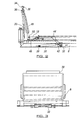
- FIG. 1 there is illustrated a vehicle 2 of a type with which the cover assembly of the invention can be used.
- the vehicle comprises a vehicle cab 4, chassis 6 which depends to the rear of the vehicle, wheels 8 and lifting arms 10, with one lifting arm being provided at each side of the vehicle chassis.
- the lifting arms 10 are provided to allow chains 12 suspended therefrom, to contact with and move a container in the form of a skip 14 between the position shown in Figure 1 in which the same is mounted on the vehicle chassis, for transport, and a position to the rear of the vehicle chassis (shown in broken lines) which allows the skip to be deposited and left to be filled with loose material, or alternatively to be left and the loose material therein to be processed or discarded.
- Figure 2 illustrates the front end of vehicle chassis of Figure 1 , with a cover assembly 18 fitted thereto and without a skip in position for ease of reference.
- the assembly comprises first and second structures 20, one provided on each side of the vehicle chassis and one example of which is shown in Figure 2 .
- the structures are provided in a position such that the same can respectively pass externally of the lifting arm 10 on each side of the vehicle.
- the structures 20 are, in the embodiment shown in Figures 2-4d located at one end 28, on the chassis 6 with a ram 30 connected to a rotational shaft 32 shown in Figure 3 which passes across the width of the chassis.
- a cross-member 36 which extends between the respective free ends 34 along with a roller on which is wound part of the cover sheet material 40 (not shown).
- the roller is typically spring loaded to allow tension to be maintained in the sheet material as it is being wound and unwound between storage and extended conditions. This prevents sagging and ensures smooth movement between positions.
- the cam acts on the next member 44 of the portion which is an elbow joint pivotally connected to member 46.
- the relative angular position of member 44 with respect to member 46 is controlled via movement of the ram 48 mounted to act on the same about pivot point 50.
- each of the actuation means structures 20 comprise a rotational drive 70 mounted on the chassis 6 and which can be connected via a linking shaft 72 passing across the chassis.
- the structures free ends 80 are each connected to be pivotally moved about axis 74 by the drive 70 at each side of the chassis.
- the remainder of each structure 20 comprises members 76, 78 leading to free end 80 with cross member 82 and roller 84 around which the sheet material is wound.
- rotation of the drive means 70 causes movement of the structures 20 as indicated by arrow 86.
- Figures 4a-d illustrate the movement of the cover assembly 18 between storage and extended positions, which is similar in both embodiments of the invention, with reference to a vehicle chassis 6 with a skip 14 mounted thereon and the lifting arms 10 shown. Although shown with the structures 20 of figures 2 and 3 it should be appreciated that the movement achieved is similar in the embodiment of figures 5a-b .
- the cover assembly 18 can be provided in a storage position in which the sheet material is substantially all wound up on roller 38 and the structures 20 lie close to the chassis 6 and therefore are provided in a position substantially out of the way of the skip, and thereby minimising the risk of damage to the cover assembly, by the movement of the skip to and from the vehicle chassis.
- the rotation of the structures 20 is progressive to cause portion 44 to rotate about shaft pivot axis 32, in a desired manner as shown in Figures 4b-d so as to cause member 46 to move and allow the sheet material 40 to un wound from roller 38 and move over the top of the skip as shown in figure 4b and when nearly fully extended the cover is lowered to contact over the angled top edges 56 of the skip 14 and which top edges define the non-planer opening into the skip.
- the ability to move the structures 20 in the manner described means that the sheet material does not become snagged on the skip opening edges and/or is not hindered by varying container sizes and/or does not discriminate in operation with respect to the container size as it moves between the storage position of Figure 4a , through the position of Figure 4b and c and to the fully extended position of Figure 4d .
- the structures can be provided such that the required reach of the free end of the structures 20 is sufficient to bring the end of the sheet material at roller 38, 84 to lie at a position below the opening 16 of the skip 14.
- the sheet material 40 extends across the opening 16 of the skip and also extends down the end walls 64, 66 to the base 68 of the skip. This therefore ensures that the loose material in the skip is properly enclosed and there is a minimal risk of the same leaving the skip or vehicle chassis through the opening 16 during transit.
- the opposing end 90 of the sheet material is fixed in position below the opening and in line with the base of the skip so the opening and opposing end walls of the skip are enclosed.
- the movement of the cover assembly between the storage and extended position is automated such that once commenced by the activation of suitable control means the cover assembly automatically moves to one or the other of the positions shown in Figures 4a or 4d as appropriate.
- the cover sheet material is preferably pleated with pleats running parallel to the length of the container such that when in the storage and winding stages the width of the sheet material is at its narrowest with the pleats not extended, but when in the in use position the pleats expand to allow the width of the sheet material to expand to overlie, and preferably overlap the width of the skip opening.
- This therefore allows the cover assembly to be provided in a form in which the sheet material or mechanism do not conflict with the container or lifting arms of the same and operation of the same to allow the mounting and demounting of the container.
- the pleats allow the sheet material to expand at the appropriate time to allow the full width of the opening to be covered.
- a cover assembly and apparatus which allows for effective implementation of a means to allow waste or other material to be retained within a skip during transport of the same. This ensures that the waste material does not represent a hazard either to other motorists or environmentally.
- the ease of implementation also makes it more attractive to be used by the vehicle operator.
Landscapes
- Engineering & Computer Science (AREA)
- Mechanical Engineering (AREA)
- Transportation (AREA)
- Buffer Packaging (AREA)
- Tents Or Canopies (AREA)
Applications Claiming Priority (1)
| Application Number | Priority Date | Filing Date | Title |
|---|---|---|---|
| GB0703840A GB0703840D0 (en) | 2007-02-28 | 2007-02-28 | Apparatus for enclosing Vehicle Transported Material |
Publications (2)
| Publication Number | Publication Date |
|---|---|
| EP1964703A2 true EP1964703A2 (de) | 2008-09-03 |
| EP1964703A3 EP1964703A3 (de) | 2009-11-18 |
Family
ID=37965634
Family Applications (1)
| Application Number | Title | Priority Date | Filing Date |
|---|---|---|---|
| EP08250674A Withdrawn EP1964703A3 (de) | 2007-02-28 | 2008-02-28 | Vorrichtung zum Verpacken von fahrzeugtransportiertem Material |
Country Status (2)
| Country | Link |
|---|---|
| EP (1) | EP1964703A3 (de) |
| GB (1) | GB0703840D0 (de) |
Cited By (1)
| Publication number | Priority date | Publication date | Assignee | Title |
|---|---|---|---|---|
| GB2474063A (en) * | 2009-10-03 | 2011-04-06 | Steve William Hines | Cover for skip containers |
Citations (2)
| Publication number | Priority date | Publication date | Assignee | Title |
|---|---|---|---|---|
| USRE36135E (en) | 1993-03-04 | 1999-03-09 | O'brian; Woody V. | Truck container cover |
| US6237985B1 (en) | 2000-01-24 | 2001-05-29 | O'brian Woody V. | Cover system for truck containers |
Family Cites Families (4)
| Publication number | Priority date | Publication date | Assignee | Title |
|---|---|---|---|---|
| US4126351A (en) * | 1976-06-15 | 1978-11-21 | Toneray Covers, Inc. | Cover for an open body |
| US6129501A (en) * | 1999-06-01 | 2000-10-10 | Pioneer Consolidated Corporation | Covering system for a load lugger type truck |
| GB0118363D0 (en) * | 2001-07-27 | 2001-09-19 | Wood Robert A | Container cover |
| GB0319589D0 (en) * | 2003-08-20 | 2003-09-24 | Reynolds Boughton Ltd | Apparatus for deploying a vehicle load cover and vehicles incorporatiing such apparatus |
-
2007
- 2007-02-28 GB GB0703840A patent/GB0703840D0/en not_active Ceased
-
2008
- 2008-02-28 EP EP08250674A patent/EP1964703A3/de not_active Withdrawn
Patent Citations (2)
| Publication number | Priority date | Publication date | Assignee | Title |
|---|---|---|---|---|
| USRE36135E (en) | 1993-03-04 | 1999-03-09 | O'brian; Woody V. | Truck container cover |
| US6237985B1 (en) | 2000-01-24 | 2001-05-29 | O'brian Woody V. | Cover system for truck containers |
Cited By (2)
| Publication number | Priority date | Publication date | Assignee | Title |
|---|---|---|---|---|
| GB2474063A (en) * | 2009-10-03 | 2011-04-06 | Steve William Hines | Cover for skip containers |
| GB2474063B (en) * | 2009-10-03 | 2015-03-18 | Steve William Hines | Cover system for a skip container mounted on a vehicle |
Also Published As
| Publication number | Publication date |
|---|---|
| GB0703840D0 (en) | 2007-04-11 |
| EP1964703A3 (de) | 2009-11-18 |
Similar Documents
| Publication | Publication Date | Title |
|---|---|---|
| US5829818A (en) | Covering device for a vehicle container | |
| US5125713A (en) | Cover for open topped compartments which is movable between stowed and covering positions | |
| US3964781A (en) | Cover assembly for open top truck bodies | |
| CA2743810C (en) | Apparatus and method for applying a tarp to trucking cargo | |
| US6974176B2 (en) | Container covering apparatus | |
| US3498666A (en) | Rollup load cover apparatus for dump bodies | |
| US7275780B2 (en) | Dual tarp cover system | |
| US4095840A (en) | Retractable cover for a truck body | |
| KR101765031B1 (ko) | 화물차량의 적재함 자동덮개 | |
| US6575518B1 (en) | Flexible cover system for an open-topped container | |
| US6623038B2 (en) | Automatic lifting mud flap assembly | |
| US6805395B2 (en) | Tarpaulin rod securing device | |
| US5573365A (en) | Tarp loader and related method | |
| US6361100B1 (en) | Tarp retraction system | |
| EP1964703A2 (de) | Vorrichtung zum Verpacken von fahrzeugtransportiertem Material | |
| DE102015216028A1 (de) | Lastentransportbehälter mit Rollplane und damit ausgerüstetes Lastentransportfahrzeug | |
| KR20190019583A (ko) | 적재함 자동덮개의 과적방지장치 | |
| EP0454171B1 (de) | Gerät zur staubfreien Entladung von Schüttgütern | |
| DE60014494T2 (de) | Abdecksystem für Absetzkipper | |
| GB2410478A (en) | Stowable tarpaulin for trucks | |
| JP3017076B2 (ja) | トラックの幌掛け装置 | |
| CA2428891C (en) | Tarpaulin rod securing device | |
| EP1279538A1 (de) | Behälterdeckel | |
| FR2487739A1 (fr) | Appareil pour bacher ou debacher les vehicules | |
| DE202008015088U1 (de) | Vorrichtung zur Abdeckung eines Behälters und Fahrzeug-Muldenbehälter |
Legal Events
| Date | Code | Title | Description |
|---|---|---|---|
| PUAI | Public reference made under article 153(3) epc to a published international application that has entered the european phase |
Free format text: ORIGINAL CODE: 0009012 |
|
| AK | Designated contracting states |
Kind code of ref document: A2 Designated state(s): AT BE BG CH CY CZ DE DK EE ES FI FR GB GR HR HU IE IS IT LI LT LU LV MC MT NL NO PL PT RO SE SI SK TR |
|
| AX | Request for extension of the european patent |
Extension state: AL BA MK RS |
|
| PUAL | Search report despatched |
Free format text: ORIGINAL CODE: 0009013 |
|
| AK | Designated contracting states |
Kind code of ref document: A3 Designated state(s): AT BE BG CH CY CZ DE DK EE ES FI FR GB GR HR HU IE IS IT LI LT LU LV MC MT NL NO PL PT RO SE SI SK TR |
|
| AX | Request for extension of the european patent |
Extension state: AL BA MK RS |
|
| RIC1 | Information provided on ipc code assigned before grant |
Ipc: B60P 1/48 20060101ALI20091015BHEP Ipc: B60J 7/08 20060101AFI20080605BHEP |
|
| TPAC | Observations by third parties |
Free format text: ORIGINAL CODE: EPIDOSNTIPA |
|
| AKX | Designation fees paid |
Designated state(s): AT BE BG CH CY CZ DE DK EE ES FI FR GB GR HR HU IE IS IT LI LT LU LV MC MT NL NO PL PT RO SE SI SK TR |
|
| STAA | Information on the status of an ep patent application or granted ep patent |
Free format text: STATUS: THE APPLICATION IS DEEMED TO BE WITHDRAWN |
|
| 18D | Application deemed to be withdrawn |
Effective date: 20100519 |