EP1964604A2 - Procédé et dispositif destinés à la fabrication continue d'un mélange d'au moins deux phases liquides - Google Patents
Procédé et dispositif destinés à la fabrication continue d'un mélange d'au moins deux phases liquides Download PDFInfo
- Publication number
- EP1964604A2 EP1964604A2 EP08150816A EP08150816A EP1964604A2 EP 1964604 A2 EP1964604 A2 EP 1964604A2 EP 08150816 A EP08150816 A EP 08150816A EP 08150816 A EP08150816 A EP 08150816A EP 1964604 A2 EP1964604 A2 EP 1964604A2
- Authority
- EP
- European Patent Office
- Prior art keywords
- mixing vessel
- phases
- discharge line
- longitudinal axis
- supply lines
- Prior art date
- Legal status (The legal status is an assumption and is not a legal conclusion. Google has not performed a legal analysis and makes no representation as to the accuracy of the status listed.)
- Withdrawn
Links
Images


Classifications
-
- B—PERFORMING OPERATIONS; TRANSPORTING
- B01—PHYSICAL OR CHEMICAL PROCESSES OR APPARATUS IN GENERAL
- B01F—MIXING, e.g. DISSOLVING, EMULSIFYING OR DISPERSING
- B01F23/00—Mixing according to the phases to be mixed, e.g. dispersing or emulsifying
- B01F23/40—Mixing liquids with liquids; Emulsifying
- B01F23/41—Emulsifying
-
- B—PERFORMING OPERATIONS; TRANSPORTING
- B01—PHYSICAL OR CHEMICAL PROCESSES OR APPARATUS IN GENERAL
- B01F—MIXING, e.g. DISSOLVING, EMULSIFYING OR DISPERSING
- B01F27/00—Mixers with rotary stirring devices in fixed receptacles; Kneaders
- B01F27/05—Stirrers
- B01F27/11—Stirrers characterised by the configuration of the stirrers
- B01F27/19—Stirrers with two or more mixing elements mounted in sequence on the same axis
- B01F27/191—Stirrers with two or more mixing elements mounted in sequence on the same axis with similar elements
-
- B—PERFORMING OPERATIONS; TRANSPORTING
- B01—PHYSICAL OR CHEMICAL PROCESSES OR APPARATUS IN GENERAL
- B01F—MIXING, e.g. DISSOLVING, EMULSIFYING OR DISPERSING
- B01F27/00—Mixers with rotary stirring devices in fixed receptacles; Kneaders
- B01F27/50—Pipe mixers, i.e. mixers wherein the materials to be mixed flow continuously through pipes, e.g. column mixers
-
- B—PERFORMING OPERATIONS; TRANSPORTING
- B01—PHYSICAL OR CHEMICAL PROCESSES OR APPARATUS IN GENERAL
- B01F—MIXING, e.g. DISSOLVING, EMULSIFYING OR DISPERSING
- B01F27/00—Mixers with rotary stirring devices in fixed receptacles; Kneaders
- B01F27/80—Mixers with rotary stirring devices in fixed receptacles; Kneaders with stirrers rotating about a substantially vertical axis
- B01F27/90—Mixers with rotary stirring devices in fixed receptacles; Kneaders with stirrers rotating about a substantially vertical axis with paddles or arms
- B01F27/902—Mixers with rotary stirring devices in fixed receptacles; Kneaders with stirrers rotating about a substantially vertical axis with paddles or arms cooperating with intermeshing elements fixed on the receptacle walls
-
- B—PERFORMING OPERATIONS; TRANSPORTING
- B01—PHYSICAL OR CHEMICAL PROCESSES OR APPARATUS IN GENERAL
- B01F—MIXING, e.g. DISSOLVING, EMULSIFYING OR DISPERSING
- B01F35/00—Accessories for mixers; Auxiliary operations or auxiliary devices; Parts or details of general application
- B01F35/50—Mixing receptacles
-
- B—PERFORMING OPERATIONS; TRANSPORTING
- B01—PHYSICAL OR CHEMICAL PROCESSES OR APPARATUS IN GENERAL
- B01F—MIXING, e.g. DISSOLVING, EMULSIFYING OR DISPERSING
- B01F27/00—Mixers with rotary stirring devices in fixed receptacles; Kneaders
- B01F27/05—Stirrers
- B01F27/11—Stirrers characterised by the configuration of the stirrers
- B01F27/113—Propeller-shaped stirrers for producing an axial flow, e.g. shaped like a ship or aircraft propeller
Definitions
- the invention relates to an apparatus and a method for the continuous production of a mixture of at least two flowable phases, in particular for the preparation of emulsions or dispersions.
- a device has a closed on all sides, about its longitudinal axis rotationally symmetric or rotationally symmetrical mixing vessel. It also comprises at least two supply lines leading into the mixing vessel for introducing a respective flowable phase and at least one discharge line leading from the mixing vessel for discharging a mixture mixed from these phases. Furthermore, such a device has a rotatable stirrer for stirring the phases whose axis of rotation lies in the longitudinal axis of the mixing vessel.
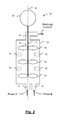
- Fig. 1 shows such a known device 1 in a schematic view, as for example. From EP 1 606 044 B1 is known.
- Two flowable phases A, B are fed to a mixing vessel 4 via two supply lines 2, 3.
- This mixing vessel also has a discharge line 5, which serves to discharge the mixture mixed from these phases.
- the supply lines 2, 3 are arranged at the lower end of the mixing vessel 4, while the discharge line 5 is provided at the upper end of the mixing vessel 4.
- the mixing vessel is cylindrical.
- the supply and discharge lines are provided perpendicular to the cylinder axis.
- a driven by a drive motor 6 stirrer 7 is provided in this known device, which sets the phases to be mixed in rotation. Due to the centrifugal forces occurring during such a rotation, the mixture is forced outwards and the air in the vessel is pressed inwards. At high stirrer speeds, accelerations of more than 1000 m / s 2 can occur. As a result, the material to be mixed, as shown by the line 8, distributed paraboloid. In these cases, the mixture, at least during a starting process, offset with air in the supply line 5 out. This is disadvantageous, since thus air is included in the further production process.
- the mixing vessel 4 is conventionally flooded before switching on the stirrer 7 with one of the phases.
- this leads to increased losses of raw materials during the starting process.
- the invention is therefore based on the problem to improve the production of mixtures of two flowable phases.
- the invention solves this problem by means of a device according to claim 1 and a method according to claim 15.
- an apparatus for the continuous production of a mixture of at least two flowable phases, in particular for the preparation of emulsions or dispersions, with a mixing vessel closed on all sides, rotationally symmetrical about its longitudinal axis or rotationally symmetrical mixing vessel, at least two supply lines leading to the mixing vessel for introducing a flowable one Phase, at least one leading out of the mixing vessel discharge line for discharging a mixture mixed from these phases and a rotatable agitator for stirring the phases whose axis of rotation lies in the longitudinal axis of the mixing vessel, wherein the discharge line is arranged in the region of a first passage of the longitudinal axis through the mixing vessel ,
- a method for continuously producing a mixture of at least two flowable phases, in particular for producing emulsions or dispersions is provided, in which at least two streams of these phases are fed separately to a mixing vessel in which they are stirred by means of a rotating stirrer, the method being carried out in a device according to the invention.
- the discharge line of the mixed product mixed in the mixing vessel is arranged in the center of an end face of the mixing vessel, namely in the region of a passage, ie intersection, of the longitudinal axis of the mixing vessel through the mixing vessel. Due to this central arrangement of the discharge line, only air is initially discharged from the mixing vessel even during a paraboloidal distribution of the mixed material in the mixing vessel during the starting process. Only when the air is substantially completely removed from the mixing vessel, the mixture is discharged from the mixing vessel without disturbing air.
- Another advantage of this design is that the pressure in the mix in the region of the wall of the mixing vessel due to the centrifugal forces is higher than at the discharge line for the mixture. In the area of the wall, however, the highest shear rates occur. Due to the high pressure occurring in the wall in this construction, the risk of cavitation is reduced. In the area of the discharge line, the pressure is lower, so that in principle there would be a greater risk of cavitation. However, only very little or no shear gradient is present in the region of the discharge line, so that the risk of cavitation in the region of the discharge line is low anyway.
- Another advantage is that already during the startup process, the resulting mixture does not have to be removed as scrap, but can be used as a product. This is possible because the mixing vessel can be filled with a rotating stirrer. This results in an already properly mixed mixture without air bubbles, which is discharged via the discharge line. Overall, the risk of air accumulation in the mixing chamber is significantly reduced according to the invention. Air is preferably discharged first. The mixing process is thus easier to approach. Premature discharge of mixed liquids at a time when there is still air in the mixing vessel is avoided.
- At least one or all supply lines are arranged in the region of a second passage of the longitudinal axis through the mixing vessel. This means that the supply lines also take place in a central end region of the mixing vessel.
- the discharge line and at least one or all supply lines can emerge from the mixing vessel either in parallel or at an angle.
- the further course of the lines can then also parallel or inclined at an angle or only parallel and then tilted at an angle or vice versa. Due to the central arrangement of the supply lines and the discharge line, the arrangement of the supply and discharge lines is subject to little restrictions, so that the respective arrangement can fulfill other requirements.
- the mixing vessel is formed like a cylinder.
- the feed and discharge lines are then located on opposite base surfaces of the cylinder.
- the mixing vessel is tapered conically to the discharge line. That the cross-section of the mixing vessel decreases in the direction of the discharge line.
- Such a construction is advantageous because due to the larger radii in the region of the supply line a higher rotational speed of the mixed material and thus a more intensive mixing effect is achieved.
- the phases to be mixed are first mixed very intensively.
- the corresponding volumes are guided in the direction of the discharge line, where the peripheral speeds, in particular in the region of the conversion of the mixing vessel are lower.
- the risk of an excess of the mixture in particular due to the increasing viscosity with increasing processing time, reduced. Overall, this results in an improved quality of the mixture to be produced.
- blades of the stirrer are adapted to the conicity of the mixing vessel, ie the vane radii decrease according to the taper to the discharge line.
- a drive motor of the stirrer is arranged in the region of the supply lines.
- the shaft of the stirrer passes through the supply line.
- flow breakers are provided in the mixing chamber.
- Such flow breakers can be arranged, for example, on the wall of the mixing vessel.
- the mixing vessel can be arranged standing or lying. In a vertical arrangement, the longitudinal axis of the mixing vessel is vertically aligned.
- the supply lines are arranged at a lower portion and the discharge lines at an upper portion of the mixing vessel. The product flow thus takes place from bottom to top, so that air bubbles can preferably escape upwards and can be removed via the discharge line.
- the longitudinal axis is arranged horizontally. This allows installation of the mixing vessel even in places with a small height. Due to the inventive arrangement of the discharge line and possibly the supply lines in a central region of the mixing vessel, the orientation of the mixing vessel is less crucial. This opens up further degrees of freedom in the design of the entire mixing device.
- Fig. 1 has already been discussed in the introduction to explain the state of the art.
- the basic concept namely the mixture of several phases in a continuous process, also applies to the present invention, so that in the above explanations to Fig. 1 Also with regard to the invention reference is made.
- Fig. 2 shows a corresponding apparatus 10 for the continuous production of a mixture of a plurality of flowable phases.
- two phases A and B are fed via separate supply lines 11, 12 to a mixing vessel 13.
- This mixing vessel has a cylindrical configuration in the illustrated embodiment.
- the supply lines 11, 12 are provided on the cylinder bottom and indeed in a central region of the cylinder bottom.
- the mixing vessel 13 has a discharge line 14.
- This discharge line is again in a central region of the front side. This middle region is determined by the passage of the cylinder longitudinal axis 15 through the mixing vessel 13 or through the end faces of the cylinder.
- the supply lines 11, 12 and the discharge line 14 enter the mixing vessel 13 parallel to the longitudinal axis 15. Of the further course of the supply and discharge lines depends on the other local conditions.
- a stirrer 16 which has a stirrer shaft 17 with stirrer blades 18 attached to this stirrer shaft 17.
- stirrer shaft 17 with stirrer blades 18 attached to this stirrer shaft 17.
- wings 18 are provided at preferably uniform intervals.
- the wings 18 are each arranged in pairs or in a group with more than two wings 18 on the shaft 17.
- flow breakers 19 are arranged on the wall of the mixing vessel 13.
- these are simple, arranged on the wall of the mixing vessel 13 strip-like or otherwise formed elements which reduce the rotational speed of the mixed material in the respective region of the flow breaker 19.
- the stirrer shaft 17, which also serves as a drive shaft for the vanes 18, is led out of the mixing vessel 13 through the discharge line 14.
- this shaft 14 is led out through one of the supply lines 11, 12.
- the agitator shaft 17 is connected to a drive motor 20 which causes the stirrer 16, in particular the stirrer blades 18, to rotate.
- the axis 15 is arranged horizontally or obliquely inclined.
- FIG. 3 shows a further embodiment of a device 10 'according to the invention.
- supply lines 21, 22 are arranged on a now conical mixing vessel 23.
- this conical mixing vessel 23 has two opposite end faces.
- the supply lines 21, 22 take place via a first end face, while a discharge line 24 is arranged opposite a second end face located on this first end side.
- the conicity of the mixing vessel 23 is selected such that the diameter of the mixing vessel and thus its cross-section from the region of the supply lines 21, 22 to the region of the discharge line 24 is smaller.
- stirrer 25 has, corresponding to Fig. 2 , several groups of Reckerhoffln 26, which are arranged on a common agitator shaft 27.
- the radii of the stirrer blades 26 are adapted to the respective cross section of the mixing vessel, that is, chosen slightly smaller than the corresponding radii of the mixing vessel 23 at these locations.
- baffles 28 are arranged to reduce the rotational speed of the material to be mixed at least locally.
- the agitator shaft 27 is in turn connected to a drive motor 29, which sets this shaft and thus the wings 26 in rotation.
- the drive motor 29 is arranged on the side of the supply lines.
- the agitator shaft 27 penetrates one of the two supply lines 21.
- the drive motor 29 may also be arranged on the opposite side of the mixing vessel 23. In this alternative arrangement, the agitator shaft 27 penetrates the discharge line 24.
- a longitudinal axis 30 of the mixing vessel can be arranged either vertically or horizontally or obliquely inclined.
- the discharge pipe 24 is disposed at an upper portion of the mixing vessel 23, while the supply pipes 21, 22 are provided at a lower portion.
- the mixing vessels are rotationally symmetrical.
- the mixing vessels can also be rotationally symmetrical about a longitudinal axis, for example, by the flow breakers being integrated directly into the respective wall of the mixing vessel.
- the invention allows due to the removal of the mixed product in the central region of one of the end sides of the mixing vessel, an improvement in the mixing properties of a mixing device and an increase in efficiency of the starting process.
- no comming arises during the starting process due to a flooding of the mixing vessel with only one phase or two not properly mixed phases.
- the invention prevents premature discharge of liquid when there is still air in the mixing vessel. Thanks to the centrifugal forces acting on the rotating material to be mixed, lower density material is conveyed to the longitudinal axis of the mixing vessel, while higher density material moves towards the wall of the mixing vessel.
- air or gas collects in a central region of the mixing vessel and is discharged due to the central arrangement of the discharge line first. As soon as the mixture reaches the area of the discharge line during a start-up process, substantially all of the air previously contained in the mixing vessel is already discharged. There is thus no or only a very small amount of mixed substance.
- Such mixing vessels are particularly suitable for processes in the production of emulsions and dispersions, in which different phases are mixed together.
- the invention provides significant advantages in moderate or low viscosity phases.
Applications Claiming Priority (1)
| Application Number | Priority Date | Filing Date | Title |
|---|---|---|---|
| DE102007005622A DE102007005622A1 (de) | 2007-01-31 | 2007-01-31 | Vorrichtung und Verfahren zur kontinuierlichen Herstellung einer Mischung aus wenigstens zwei fließfähigen Phasen |
Publications (2)
| Publication Number | Publication Date |
|---|---|
| EP1964604A2 true EP1964604A2 (fr) | 2008-09-03 |
| EP1964604A3 EP1964604A3 (fr) | 2009-03-18 |
Family
ID=39402889
Family Applications (1)
| Application Number | Title | Priority Date | Filing Date |
|---|---|---|---|
| EP08150816A Withdrawn EP1964604A3 (fr) | 2007-01-31 | 2008-01-30 | Procédé et dispositif destinés à la fabrication continue d'un mélange d'au moins deux phases liquides |
Country Status (2)
| Country | Link |
|---|---|
| EP (1) | EP1964604A3 (fr) |
| DE (1) | DE102007005622A1 (fr) |
Cited By (3)
| Publication number | Priority date | Publication date | Assignee | Title |
|---|---|---|---|---|
| WO2011138438A1 (fr) | 2010-05-07 | 2011-11-10 | Otc Gmbh | Dispositif d'émulsification pour la production en continu d'émulsions et/ou de dispersions |
| JP2012115808A (ja) * | 2010-12-03 | 2012-06-21 | Heungbo Tech Co Ltd | 均質混練機 |
| WO2017046017A1 (fr) * | 2015-09-14 | 2017-03-23 | Wacker Chemie Ag | Procédé de préparation en continu d'émulsions de silicone stables |
Families Citing this family (2)
| Publication number | Priority date | Publication date | Assignee | Title |
|---|---|---|---|---|
| DE102009040454A1 (de) * | 2009-08-27 | 2011-03-24 | Otc Verwaltungs Gmbh | Herstellung von Perlglanzdispersionen |
| US20210346855A1 (en) * | 2018-09-05 | 2021-11-11 | Tanaka Holdings Co., Ltd. | Liquid stirring apparatus |
Citations (1)
| Publication number | Priority date | Publication date | Assignee | Title |
|---|---|---|---|---|
| EP1606044B1 (fr) | 2003-03-21 | 2006-09-27 | Kemira Pigments Oy | Dispositif et procede de production continue d'emulsions ou de dispersions |
Family Cites Families (9)
| Publication number | Priority date | Publication date | Assignee | Title |
|---|---|---|---|---|
| US3807703A (en) * | 1972-10-12 | 1974-04-30 | Usm Corp | Mixer-emulsators |
| US4155657A (en) * | 1978-03-10 | 1979-05-22 | Chemed Corporation | Continuous mixer for preparing emulsions |
| SU1368182A1 (ru) * | 1985-10-08 | 1988-01-23 | Предприятие П/Я Х-5312 | Смеситель |
| CH677116A5 (fr) * | 1989-01-25 | 1991-04-15 | Inst Mikrobiologii Imeni A Kir | |
| US4951262A (en) * | 1989-04-18 | 1990-08-21 | Halliburton Company | Agitator and baffles for slurry mixing |
| US5250576A (en) * | 1991-08-12 | 1993-10-05 | The Procter & Gamble Company | Process for preparing emulsions that are polymerizable to absorbent foam materials |
| DE19818738C2 (de) * | 1998-04-27 | 2000-05-25 | Waeschle Gmbh | Verfahren und Vorrichtung zum Verringern der Feststoffkonzentration einer Dispersion aus Flüssigkeit und Feststoffpartikeln |
| US20030227817A1 (en) * | 2002-04-11 | 2003-12-11 | Mobius Technologies, Inc., A California Corporation | Mixer |
| GB0318449D0 (en) * | 2003-08-06 | 2003-09-10 | Glaxo Group Ltd | Impeller unit |
-
2007
- 2007-01-31 DE DE102007005622A patent/DE102007005622A1/de not_active Ceased
-
2008
- 2008-01-30 EP EP08150816A patent/EP1964604A3/fr not_active Withdrawn
Patent Citations (1)
| Publication number | Priority date | Publication date | Assignee | Title |
|---|---|---|---|---|
| EP1606044B1 (fr) | 2003-03-21 | 2006-09-27 | Kemira Pigments Oy | Dispositif et procede de production continue d'emulsions ou de dispersions |
Cited By (11)
| Publication number | Priority date | Publication date | Assignee | Title |
|---|---|---|---|---|
| WO2011138438A1 (fr) | 2010-05-07 | 2011-11-10 | Otc Gmbh | Dispositif d'émulsification pour la production en continu d'émulsions et/ou de dispersions |
| DE102010028774A1 (de) | 2010-05-07 | 2011-11-10 | Otc Gmbh | Emulgiereinrichtung zur kontinuierlichen Herstellung von Emulsionen und/oder Dispersionen |
| CN102946983A (zh) * | 2010-05-07 | 2013-02-27 | Otc股份有限公司 | 连续产生乳液和/或分散体的乳化装置 |
| JP2013532047A (ja) * | 2010-05-07 | 2013-08-15 | オー・ティー・シー ジー・エム・ビー・エイチ | エマルション及び/又は分散液の連続製造用乳化装置 |
| KR20130113935A (ko) * | 2010-05-07 | 2013-10-16 | 오티씨 게엠베하 | 에멀전 및/또는 분산액을 연속적으로 제조하기 위한 유화장치 |
| CN102946983B (zh) * | 2010-05-07 | 2014-12-17 | Otc股份有限公司 | 连续产生乳液和/或分散体的乳化装置 |
| US9555380B2 (en) | 2010-05-07 | 2017-01-31 | Clariant International Ag | Emulsification device for continuously producing emulsions and/or dispersions |
| US10610835B2 (en) | 2010-05-07 | 2020-04-07 | Clariant International Ag | Emulsification device for continuously producing emulsions and/or dispersions |
| JP2012115808A (ja) * | 2010-12-03 | 2012-06-21 | Heungbo Tech Co Ltd | 均質混練機 |
| WO2017046017A1 (fr) * | 2015-09-14 | 2017-03-23 | Wacker Chemie Ag | Procédé de préparation en continu d'émulsions de silicone stables |
| US10561995B2 (en) | 2015-09-14 | 2020-02-18 | Wacker Chemie Ag | Process for continuous production of stable silicone emulsions |
Also Published As
| Publication number | Publication date |
|---|---|
| EP1964604A3 (fr) | 2009-03-18 |
| DE102007005622A1 (de) | 2008-08-07 |
Similar Documents
| Publication | Publication Date | Title |
|---|---|---|
| EP0516921B1 (fr) | Agitateur de gazage | |
| EP1771241B1 (fr) | Melangeur dynamique et son utilisation | |
| EP2262582B1 (fr) | Réacteur agité et procédé pour conduire une réaction de polymérisation au moyen d'un tel réacteur agité | |
| EP2285476B1 (fr) | Système rotor-stator et procede pour la production de dispersions | |
| EP1792643B1 (fr) | Réacteur à grand volume respectivement évaporateur à couche mince combiné avec un dispositif pré-melangeur | |
| EP2720783B1 (fr) | Installation pour la dispersion de matières solides finement dispersées dans des produits de viscosité élevée | |
| DE602005003356T2 (de) | Verfahren, vorrichtung und rotor zur homogenisierung eines mediums | |
| EP3202489B1 (fr) | Dispositif destiné à homogénéiser et/ou disperser des produits fluides | |
| EP2178643B1 (fr) | Broyeur agitateur | |
| EP2140920B1 (fr) | Elément de torsion, soupape d'admission, dispositif et procédé de dégazage de liquides | |
| EP1964604A2 (fr) | Procédé et dispositif destinés à la fabrication continue d'un mélange d'au moins deux phases liquides | |
| DE4008943A1 (de) | Mischvorrichtung | |
| DE19537303B4 (de) | Vorrichtung zum Homogenisieren fließfähiger Stoffe | |
| EP1175255B1 (fr) | Procede et dispositif pour le traitement d'une matiere ou d'un melange de matieres se trouvant dans un recipient, en particulier par melange ou agitation, en rotation autour de l'axe du recipient | |
| EP0760254B1 (fr) | Dispositif pour l'homogénéisation de matériaux coulants | |
| DE102016102728A1 (de) | Vorrichtung und Verfahren zum Dispergieren mindestens einer Substanz in einem Fluid | |
| EP2683487B1 (fr) | Broyeur à billes agité | |
| EP2818234B1 (fr) | Dispositif de stockage de milieux semi-liquides | |
| DE3919828C2 (de) | Schlaufenreaktor | |
| WO2004105924A1 (fr) | Dispositif permettant de faire mousser un badigeon | |
| EP3290094A1 (fr) | Dispositif et procede de degazage d'un liquide | |
| DE2216444A1 (de) | Mischvorrichtung zur herstellung einer homogenen mischung aus mehreren stoffkomponenten | |
| DE2727088A1 (de) | Gas-fluessigkeitskontaktgeraet | |
| DE836345C (de) | Vorrichtung zum fortlaufenden Mischen zweier Stoffe | |
| EP1920822A2 (fr) | Dispositif et procédé destinés au mélange et au dégazage continus de substances solides et/ou liquides |
Legal Events
| Date | Code | Title | Description |
|---|---|---|---|
| PUAI | Public reference made under article 153(3) epc to a published international application that has entered the european phase |
Free format text: ORIGINAL CODE: 0009012 |
|
| AK | Designated contracting states |
Kind code of ref document: A2 Designated state(s): AT BE BG CH CY CZ DE DK EE ES FI FR GB GR HR HU IE IS IT LI LT LU LV MC MT NL NO PL PT RO SE SI SK TR |
|
| AX | Request for extension of the european patent |
Extension state: AL BA MK |
|
| PUAL | Search report despatched |
Free format text: ORIGINAL CODE: 0009013 |
|
| AK | Designated contracting states |
Kind code of ref document: A3 Designated state(s): AT BE BG CH CY CZ DE DK EE ES FI FR GB GR HR HU IE IS IT LI LT LU LV MC MT NL NO PL PT RO SE SI SK TR |
|
| AX | Request for extension of the european patent |
Extension state: AL BA MK |
|
| AKX | Designation fees paid | ||
| STAA | Information on the status of an ep patent application or granted ep patent |
Free format text: STATUS: THE APPLICATION IS DEEMED TO BE WITHDRAWN |
|
| 18D | Application deemed to be withdrawn |
Effective date: 20090919 |
|
| REG | Reference to a national code |
Ref country code: DE Ref legal event code: 8566 |