EP1963786B1 - Positioning pattern - Google Patents
Positioning pattern Download PDFInfo
- Publication number
- EP1963786B1 EP1963786B1 EP06799736.1A EP06799736A EP1963786B1 EP 1963786 B1 EP1963786 B1 EP 1963786B1 EP 06799736 A EP06799736 A EP 06799736A EP 1963786 B1 EP1963786 B1 EP 1963786B1
- Authority
- EP
- European Patent Office
- Prior art keywords
- points
- node
- detecting system
- point
- position detecting
- Prior art date
- Legal status (The legal status is an assumption and is not a legal conclusion. Google has not performed a legal analysis and makes no representation as to the accuracy of the status listed.)
- Not-in-force
Links
Images




Classifications
-
- G—PHYSICS
- G01—MEASURING; TESTING
- G01D—MEASURING NOT SPECIALLY ADAPTED FOR A SPECIFIC VARIABLE; ARRANGEMENTS FOR MEASURING TWO OR MORE VARIABLES NOT COVERED IN A SINGLE OTHER SUBCLASS; TARIFF METERING APPARATUS; MEASURING OR TESTING NOT OTHERWISE PROVIDED FOR
- G01D5/00—Mechanical means for transferring the output of a sensing member; Means for converting the output of a sensing member to another variable where the form or nature of the sensing member does not constrain the means for converting; Transducers not specially adapted for a specific variable
- G01D5/26—Mechanical means for transferring the output of a sensing member; Means for converting the output of a sensing member to another variable where the form or nature of the sensing member does not constrain the means for converting; Transducers not specially adapted for a specific variable characterised by optical transfer means, i.e. using infrared, visible, or ultraviolet light
- G01D5/32—Mechanical means for transferring the output of a sensing member; Means for converting the output of a sensing member to another variable where the form or nature of the sensing member does not constrain the means for converting; Transducers not specially adapted for a specific variable characterised by optical transfer means, i.e. using infrared, visible, or ultraviolet light with attenuation or whole or partial obturation of beams of light
- G01D5/34—Mechanical means for transferring the output of a sensing member; Means for converting the output of a sensing member to another variable where the form or nature of the sensing member does not constrain the means for converting; Transducers not specially adapted for a specific variable characterised by optical transfer means, i.e. using infrared, visible, or ultraviolet light with attenuation or whole or partial obturation of beams of light the beams of light being detected by photocells
- G01D5/347—Mechanical means for transferring the output of a sensing member; Means for converting the output of a sensing member to another variable where the form or nature of the sensing member does not constrain the means for converting; Transducers not specially adapted for a specific variable characterised by optical transfer means, i.e. using infrared, visible, or ultraviolet light with attenuation or whole or partial obturation of beams of light the beams of light being detected by photocells using displacement encoding scales
-
- G—PHYSICS
- G01—MEASURING; TESTING
- G01L—MEASURING FORCE, STRESS, TORQUE, WORK, MECHANICAL POWER, MECHANICAL EFFICIENCY, OR FLUID PRESSURE
- G01L3/00—Measuring torque, work, mechanical power, or mechanical efficiency, in general
- G01L3/02—Rotary-transmission dynamometers
- G01L3/04—Rotary-transmission dynamometers wherein the torque-transmitting element comprises a torsionally-flexible shaft
- G01L3/10—Rotary-transmission dynamometers wherein the torque-transmitting element comprises a torsionally-flexible shaft involving electric or magnetic means for indicating
- G01L3/12—Rotary-transmission dynamometers wherein the torque-transmitting element comprises a torsionally-flexible shaft involving electric or magnetic means for indicating involving photoelectric means
-
- G—PHYSICS
- G06—COMPUTING OR CALCULATING; COUNTING
- G06F—ELECTRIC DIGITAL DATA PROCESSING
- G06F3/00—Input arrangements for transferring data to be processed into a form capable of being handled by the computer; Output arrangements for transferring data from processing unit to output unit, e.g. interface arrangements
- G06F3/01—Input arrangements or combined input and output arrangements for interaction between user and computer
- G06F3/03—Arrangements for converting the position or the displacement of a member into a coded form
- G06F3/0304—Detection arrangements using opto-electronic means
- G06F3/0317—Detection arrangements using opto-electronic means in co-operation with a patterned surface, e.g. absolute position or relative movement detection for an optical mouse or pen positioned with respect to a coded surface
- G06F3/0321—Detection arrangements using opto-electronic means in co-operation with a patterned surface, e.g. absolute position or relative movement detection for an optical mouse or pen positioned with respect to a coded surface by optically sensing the absolute position with respect to a regularly patterned surface forming a passive digitiser, e.g. pen optically detecting position indicative tags printed on a paper sheet
-
- G—PHYSICS
- G01—MEASURING; TESTING
- G01D—MEASURING NOT SPECIALLY ADAPTED FOR A SPECIFIC VARIABLE; ARRANGEMENTS FOR MEASURING TWO OR MORE VARIABLES NOT COVERED IN A SINGLE OTHER SUBCLASS; TARIFF METERING APPARATUS; MEASURING OR TESTING NOT OTHERWISE PROVIDED FOR
- G01D2205/00—Indexing scheme relating to details of means for transferring or converting the output of a sensing member
- G01D2205/90—Two-dimensional encoders, i.e. having one or two codes extending in two directions
Definitions
- the present invention relates to a device, method and system for determining a position of an object and in particular to a vision based solution using a pattern comprising absolute position data.
- control devices Many different types have been constructed for various purposes.
- the most common control device is the so called mouse giving positioning variables in two dimensions for use in controlling operation of applications on a computer.
- Other interface control devices include the so called joystick which gives positioning variables also in two dimensions from the stick; however, by using extra buttons in conjunction with the stick it is possible to enhance the number of "positioning variables", but it should be understood that this device physically only measures positioning variables in two dimensions.
- a trackball also delivers data for two dimensions; a game pad often uses a small joystick like handle for measuring positioning variables and may extend the range of the functionality of the controller to more control data by utilizing extra buttons; a steering wheel (for computer gaming) delivers data in one dimension.
- control device only gives reference measurements and not absolute measurements, meaning that for an application relying on absolute coordinates of the control device to function properly complex computing is needed to continuously keep track of the location of the control device. Still such devices either need to be calibrated regularly or they will continuously build up an error that quickly may become critical depending on application.
- positioning data is used for determining the position of an object, and in many cases absolute measuring solutions are used, however, they are often quite complex and not cost effective to be used in low cost applications.
- Vision based systems have been utilized previously and often used in conjunction with reference points, for instance in vision based positioning systems for determining the position of vehicles or objects in movement. These systems may be mounted on the vehicle or object determining the position using reference points In the surrounding area or on an external position determining the position using reference points on the vehicle or object. These systems generally are quite complex and demand high quality vision systems and high computational powers.
- US patent 5965879 wherein an one-dimensional absolute optical linear or rotary encoder is shown.
- This solution uses identical fiducial markers for finding a position of an object.
- the fiducial position is calculated in one direction namely the direction of travel
- Another such system is presented in US patent 6765195 wherein a two dimensional absolute optical encoder Is shown.
- This solution uses two different fiducial markers for determining the position of an object.
- the fiducials are identical across all encoded positions and arranged in a manner which is strictly periodic in each direction of travel. Both of these systems illustrate systems which need complex optical solutions and where size of patterns is of the order a few micrometers of dimension. They do not provide bending or rotational information either.
- reference numeral 1 generally denotes a measuring device 1 as seen from a cross sectional view according to an embodiment of the present invention.
- the device 1 comprises an image acquiring device 3 positioned a distance away from an object 2 of interest.
- the device 1 is enclosed in a casing 8 and electrical connectors 9, and optionally a control interface 10.
- the object of interest is a shaft 2 and the device 1 is mounted on the shaft 2 supported by two bearings 5 and 6.
- the image acquiring device 3 is mounted close to the surface of the object 2 and the device 1 may be arranged in such a way as to form a cavity 7 which may be essentially sealed in order to decrease the risk of allowing dirt or other disturbing factors to enter into the cavity 7.
- Fig. 1 a is a cross sectional view of the embodiment across la from Fig. 1b which is a side view of the embodiment.
- Signals from the image acquiring device 3 are transferred to a processing device 200, illustrated in Fig. 2 , via a connector 207, for image processing and signal conditioning in order to provide a signal or signals indicative of the position of the object 2 to some external device connected to the processing device using a connector 203.
- the processing device may include a processor 201, memory unit (or units) 202, image processing unit 204, and other units 205 and 206 depending on application for the measuring device 1.
- the processing unit may have a communication interface for communicating with external devices, or optional units attached to the control device 1. Such optional units may include, but is not limited to, force feedback, clamping devices, or similar interaction devices for interacting with a user of the control device.
- Interfaces for both communicating with external devices or internal sensor inputs may be provided through any suitable connector or connectors as understood by the person skilled in the art, including, but not limited to, USB (universal serial bus), Firewire, RS232, RS485, Ethernet, Centronics parallel port, GPIB (general purpose interface bus), different wireless interfaces (e.g. Bluetooth and WLAN), and so on.
- USB universal serial bus
- Firewire Firewire
- RS232 Firewire
- RS485 Firewire
- Ethernet Firewire
- Centronics parallel port RS232, RS485, Ethernet
- Centronics parallel port GPIB (general purpose interface bus)
- GPIB general purpose interface bus
- different wireless interfaces e.g. Bluetooth and WLAN
- the processing device 200 may conveniently be situated within the measuring device it self or provided as an external stand alone device depending on application.
- an image acquiring device 3 is used for obtaining the position of the object 2, however, other sensor types may be utilized which are arranged to obtain positioning data, for instance a magnetic sensor acquiring positions of magnetic "points" on the object 2.
- Non-contacting sensor means may advantageously be utilized since part of the object 2 is encapsulated within the casing 8 of the measuring device 1; however, these types of sensors may be used even if there is no encapsulation. Therefore, there is a small amount of disturbances that can influence the reading, such as dirt, light, or stray magnetic fields.
- the casing 8 is made of an electrically conducting material with magnetic shielding properties in order to reduce the risk of influencing a magnetic sensor measuring the position of the object 2.
- the pattern 4 and camera 3 may be provided in an enclosure for reducing the risk of contamination from the external environment, for instance dirt or light.
- contacting sensors can also be used, including, but not limited to, slip rings, impedance measurements, voltage dividers, digital encoders, and capacitive measurements.
- a functional pattern comprising node points 301 to 304 and information points 305 to 311.
- Points may have different sizes and with different filling ratios and these configurations will have a functional effect when reading them with a reading device such as a camera.
- virtual points 312-315 are also indicated, these are not markings that are present in the actual solution but may optionally be used for analysis purposes as reference points in the analysis algorithm.
- illumination 320, 330, 340, 350 may be required depending on the application and environment. In this case four light emitting devices (e.g.
- LED Light emitting diodes
- light bulb with a filament
- laser diodes laser diodes
- infrared emitters infrared emitters may be suitable for instance when there is some kind of contamination layer which do not absorb or reflect infrared light
- fluorescent tube fluorescent tube
- the pattern is repeated with variations all over the object that passes in front of the camera so as to provide possibility of obtaining an absolute position of the object.
- the invention is not limited to four illumination devices but any suitable number may be used, and in some cases where ambient light from the environment is sufficient no extra illumination is necessary.
- the illumination may be of any suitable frequency, for instance but not limited to: visible light, infrared light, ultraviolet light, x-ray, or microwaves.
- Node points 301 to 304 may be as a ring 301, 302 or a ring with a dot 303, 304 inside (they may also be a filled circle).
- Node points 301 to 304 are used for determining the position in the camera window and type of point for a certain application and the determination is made in two steps: a first step for detecting the node points and a second for determining the node points' position with higher accuracy.
- the reason for doing the analysis in two steps is to reduce the computational power needed at each certain time unit.
- the more accurate determining may be made using a symmetry analysis, a centre of gravity analysis or similar method to determine the center of the point, a so called centroid calculation.
- This centroid calculation is done in at least two directions in order to acquire information about position in at least two directions (and possibly also rotational dimensionality of the object).
- the node points need to be large enough to provide a suitable number of pixels to do analysis on.
- the node points are advantageously not filled but rings with or without a dot in the center. This provides the analysis method chosen with a gradient feature both on the outside and the inside of the node point which enhances the accuracy of the center of the node analysis.
- the dot in the center of the ring may be used for providing a directional feature of the pattern, i.e. it will be easier for the analysis system since it will acquire reference points (or lines) on regular basis.
- dot provided rings may be used every fifth degree around the object or so. For instance one may use undotted rings on an "equatorial" line of pattern groups and on each "southern” and “northern” 5 degrees from the "equatorial" line of pattern groups node points are used with dotted rings.
- Other shapes of the points may be used, for instance rectangularly or elliptically shaped points (these may be used for providing another way of obtaining directional and rotational information; i.e. the ellipse has a built in directional behavior from the shape).
- Other shapes may include quadratic, triangularly or irregularly shaped forms.
- Information points 305 to 311 groups are centered around one node point, between two node points or between four node points.
- the information points are used for determining the absolute position of the pattern group.
- the information points have advantageously a different size than the node points in order to distinguish them from the node points. They are often smaller since they are not used for determining the position of the pattern with respect to the camera window but are used for determining the absolute coordinate of the identified group with respect to the object containing the pattern. Also these smaller information points may be of different character: filled circles, rings, and non existent (the non-existence of a point also provides information, if the system knows that a certain geometrical area may comprise points).
- the analysis system determines the pattern group of the information points and determines the relative position to each other and type of point character. Since the system knows the number of information points used in the information pattern groups, the system may determine which type of points is present at each location and from this analysis determine the absolute position of that information pattern group. Using seven information points as in Fig. 3 with these three different characters a very large number of unique combination are available which is sufficient for reasonable sized objects and chosen accuracy; however, it should be understood that a different number of information points may be used depending on application. Different shapes of the information points and/or node points may be utilized, the invention is not limited to round shapes but squares, triangles or any other geometrical shape (even irregular shapes) may be used.
- the size of the node and/or information points may be used for providing the points with different type of information and in such a case, the size may be determined from the area of each point. The size may then be used even for irregular shapes since each point may be determined by the number of pixels that build up an image of the point.
- Node and information points may be the same points, i.e. they need not be of different size, type or location as long as the system may use the pattern for determining location of the point on the object and a position relative the sensing device. In an application with curved surfaces, the pattern is applied in an angular system rather than in a Cartesian coordinate system; i.e. for instance every 5 th degree of the objects perimeter for a spherical object instead of every 5 mm around the perimeter.
- the pattern may be applied in a Cartesian coordinate system manner with appropriate adjustments in the calibration and/or analysis of the acquired pattern even for a non flat surface, i.e. a curved surface.
- the pattern may be applied with any suitable application technique depending on type of surface and object, e.g. laser markings, engraving, etching, hobbing, knurling, scribing, dying, ink jet techniques, applied directly on the object or on a film or any other suitable material in turn fixed to the object, and so on as understood by the person skilled in the art.
- any suitable application technique e.g. laser markings, engraving, etching, hobbing, knurling, scribing, dying, ink jet techniques, applied directly on the object or on a film or any other suitable material in turn fixed to the object, and so on as understood by the person skilled in the art.
- an injection-molded sleeve may be provided with pattern groups already at the production of the sleeve and the sleeve may in turn be applied to an object of interest.
- Points in the pattern group may have different depths and depth profiles in the material onto which the points are applied. This may be convenient for providing different contrast configurations. For instance a point with a conical narrowing depth wise will be seen by a camera as being darker than a point with a flat bottom surface.
- the pattern may stand out from the object, for instance as cones sticking out from the material; this may be useful for instance for determining distance between the sensing device and the object.
- the pattern may advantageously be arranged depending on type of surface, for instance to be suited for either essentially flat surfaces or curved surfaces.
- the present invention is particularly suited for use on curved surfaces.
- the pattern may provide information about x and y position of the object as well as rotation or bending of the object in relation to the sensing device.
- the pattern may provide information about x and y position of the object as well as rotation or bending of the object in relation to the sensing device.
- an algorithm is used to determine the type of pattern and the relative positions and filling grade of each point.
- the pixel values obtained from the camera comprise for instance grey scale data (or they may be color coded if the actual node and/or information points comprise color data), e.g. values in a range between 0 and 255.
- the analysis comprise setting a threshold value for where the system determines that a pixel comprise a marking or not. This threshold is settable (software or hardware vise) and may be controlled according to ambient light or dirt on the object upon where the markings are set.
- a pixel completely is filled by a marked point, it may be read for example as 40 and a pixel completely without a marking may be read for example as 180, a pixel only partly filled by a marking may for example read as 90, which would be below a threshold of 100 and therefore determined as comprising a marking. It is possible to use these partly filled pixels in the analysis to enhance the accuracy of the position determination.
- the analysis scans over all pixels received in a frame and determines any node and information points in the frame. It may be arranged to filter out points below or over a certain number of pixels since the node and information points have a known size in pixels; e.g.
- node points below 5 or larger than 15 may be filtered out for an application where node points have a size in the camera frame of ca 10 pixels and information points a size of ca 6 pixels.
- the present invention is not limited to the above exemplified values of grey scales and sizes of camera readings. This is very dependent on application and sought after accuracy of the system and may be varied in a wide range. For instance, in grey scale solutions, completely black may be represented by a 0 or a figure 255 and completely white with 255 or 0 accordingly.
- the pixel sizes of node and information points may be chosen to any other suitable value as understood by the person skilled in the art depending for instance on camera setting, application, and distance between the camera and the pattern.
- Fig. 4 illustrates schematically a torque measuring device 400 using the present invention.
- Using the patterns for acquiring position of an object it is possible to measure strains in the object 402. This can be done by comparing two different positions of the object 402 and measuring the relative position between them. If there is a deviation between them this can be a result of strain; this is true for instance for a torque present in a shaft 402 where the torque induces an angular shift in the shaft 402 between two different points in the longitudinal direction of the shaft 402.
- the accuracy of the measuring device is dependent on the spacing of the two measuring points; the longer the distance between the two points the larger angular deflection and thus the better accuracy.
- a single sensing device e.g.
- an image acquiring device is used measuring two separated patterns at the same time and in order to increase the angular deflection two sleeves 403 and 404 is used in such a manner as to amplify the angular deviation. This is accomplished by fixing one side 406 and 405 of each sleeve 403 and 404 to the shaft 402. Any angular deviation at each of the fixation points will be transferred to each sleeve 403, 404 and therefore will each free end 408, 409 of each sleeve 403, 404 deviate with the same angular shift as each fixed end 405, 406. Patterns 4 and 4' on the sleeves 403, 404 at each free end 408, 409 may be measured with the same sensing device 401.
- This type of solution has a benefit in that there is no need for calibration between a plurality of sensing devices, for instance timing characteristics that might be a problem if the shaft 402 is turning at speeds similar or higher than the sensing rate. For instance, in the case of image acquisition devices, the frame rate of the image acquisition device as compared to the turning speed of the shaft 402 will set the upper limit on the accuracy. However, for applications using sensing devices with high sensing rates or in applications where the object 402 is moving at a speed below the sensing rate, a plurality of sensing devices can be used and such cases sleeves 403, 404 are not needed but instead the pattern may be located directly on the shaft 402. The system may also provide information about the translational position of the shaft 402 and/or bending of the shaft 402.
- the system may operate as an X, Y, and Z positioning device as well as providing information about torque and bending.
- the system may also provide information about rotational speed of the shaft.
- FIG. 5 illustrates an embodiment of the present invention utilized on a ball or part of a ball like structure for use in for instance a computer interface device such as a track ball, or a robot arm interface for keeping track of the position of the robot arm, in a 3D digitizer for measuring and digitizing the form of a three dimensional object.
- a positioning system according to this embodiment comprises a ball 501 with a pattern 504 according to the present invention arranged on the ball 501.
- a pattern detection system 503 comprising a computational unit (not shown) and e.g. a camera 502 detecting the position of the pattern with respect to the detection system and being able to output via an interface (not shown) images or absolute coordinates of the ball 501, depending on if the system have a computational unit or not. Since the ball and the pattern may be made in a resilient material it can be used as a load bearing element. This will be discussed more in detail later on in this document.
- Fig. 6 is a schematic block diagram of a method (steps 601 to 605) for calibrating the measurement device according to the present invention.
- a manufacturing rig where the object is fixed to in a rotatable manner (if the object is at least partly with a spherical or cylindrical geometry).
- the manufacturing rig may be equipped with a reference position determining device, such as an angular encoder for determination of the angular position of the object during rotation in the rig.
- the object may rotate while the pattern is applied thus ensuring that the pattern is applied in an angular manner (i.e. not according to a Cartesian coordinate system as explained earlier).
- a calibration system may be located, reading point values when rotating the object and obtaining angular measurement data from the reference position determining device.
- One may then obtain reference values of positions of the node points and correspondingly a calibration database may be created that may be used in devices using the present invention in order to further increase the accuracy of the measurements of the absolute position of the object in application.
- a similar calibration technique may be applied to the system on site for recalibration or when the system is applied to an existing application, e.g. a sleeve or film with the pattern group applied to a shaft already mounted in its proper application, it may these types of circumstances be of interest to calibrate the system in site.
- the calibration method may comprise the following steps:
- Adjustment of thresholds and lighting conditions may be utilized by reading background areas (i.e. areas without any pixels in) for obtaining a current light condition. It is then possible to set a new threshold value between marked or unmarked pixels and also it is possible to adjust the intensity from the illumination devices 320, 330, 340, 350 by controlling the light output from these illumination devices.
- One method of determining the background lighting conditions may be as follows: The camera frame window may be divided into 16 sectors and with the pattern exemplified earlier one may find four sectors where no points are present (or at least only partly present), one may find these four sectors by finding four virtual points 312-315 located between each node point on a line between node points (a line not comprising information points).
- the sectors where in these four virtual points are located may be used as background sectors for determining the background lighting conditions.
- a number of such readings may be used in a cumulative and averaging algorithm to enhance the accuracy of this background lighting determination.
- the number of sectors and background sectors are not limited to the above mentioned but different number of such sectors may be used.
- FIG. 7 illustrating an embodiment of the present invention of a torque measuring device 710, where two lines 4, 4' of pattern groupings are located on a shaft 702.
- Two cameras 703, 705 each take readings from one such line 4, 4' and relay either image information or position data to a central processing device 730 via cables 701, 702 and interface units 704, 706. Since the two lines of pattern groupings are separated along the shaft longitudinal direction, when a torque is applied to the shaft they will be slightly offset each other due to an angular twist of the shaft that occurs when it is subjected to a torque. This offset is proportional to the applied torque and it is thus possible to measure the torque by measuring the angular twist in the shaft.
- the two lines of pattern groupings should be sufficiently separated by a distance d such as to provide a measurable angular twist.
- the separation needed in order to acquire a sufficient measurable angular twist is a function of camera resolution, range of applied torque and desired resolution of measurement, outer diameter of shaft, and inner diameter if shaft is a tube.
- the two cameras are reduced to one camera measuring on both patterns at the same time by relaying images to the camera from the two locations. This can be done by relaying the images using optical fibers, using mirrors, or a prism.
- the camera may be an infrared sensitive camera detecting different temperatures in the object and the pattern on the object may be arranged with different temperature characteristics. Illumination in the infrared range may be provided in this type of solution in order to provide adequate illumination contrast and other parameters.
- the present invention of determining absolute positions on objects may be utilized in a number of applications since the camera and computational systems may comprise low cost devices. Applications range from such as for instance a torque meter measuring torque in a non contact manner, for use in vehicles measuring torque in a shaft in the drive line (for optimizing combustion processes or output power to each wheel) or in the steering wheel shaft (for use in power steering), in a bicycle (e.g. a spinning cycle used for exercise purposes), on any type of shaft where toque is of interest to measure.
- the invention may also be used for measuring other parameter related to a position of the object of interest, such parameters include, but are not limited to, force, rotational speed, position, and bending.
- the present invention may be used for instance also as a sensor for ABS (Automatic Break Systems) application, for anti spin sensors, or in CNC (computerized numerical control) machines in manufacturing for positioning the tool used in the CNC machine.
- a one camera solution measuring pattern groups on an object with only rotational translation will provide an accurate and low cost solution for determining the angular position of the object, for instance as an angular encoder but with a large increase in resolution.
- the object is a wheel like object, e.g. a disc with a thickness sufficient enough to provide space for the pattern
- the pattern may be provided on the wheel outer circumference or on a side of the wheel.
- the present invention may be utilized in an articulating arm (for determining and digitizing the geometrical proportions of an object) by combining a number of different embodiments of the present invention.
- An articulating arm often comprises a number of joints, each with a position sensor for determining the position of each part comprising the arm. With a number of such angular joints the articulating arm can be used for determining the geometrical dimensions of the object and providing these to a computer aided design system (CAD) for obtaining the geometrical dimensions into a computational system.
- CAD computer aided design system
- An articulating arm may comprise joints with a combination of 3D and 1 D sensing devices, for instance a first 1 D sensor located at the base of the arm, a second 1 D sensor in each 1 D joint between each arm section, and a 3D sensing device holding a probe used for determining the position of an test object under scrutiny of the articulating arm.
- the number and type of sensing devices forming part of the articulating arm may be varied in our configurations accomplishing the same functionality.
- the first 1 D sensing device keeps track of the overall rotational position of the arm with respect to the surface where upon the articulating arm arrangement stands on, the second and subsequent 1 D sensing devices in each joint between each arm section each keep track of a rotation position, and the 3D sensing device keeps track of the probe position relative the arm. Taking measurements from each sensing device into consideration the position of the probe relative the test object may be determined and the geometrical configuration of the test object digitized.
- the present invention may also be used in a theodolite which is an instrument for measuring both horizontal and vertical angles, for instance for use in triangulation applications.
- the theodolite comprises a telescope mounted in such a manner as to be movably within two perpendicular axes: a horizontal axis and a vertical axis.
- the theodolite is often mounted on a tripod placed precisely and vertically over the point to be measured and its vertical axis aligned with local gravity.
- the present invention may be used for acquiring absolute positioning data for the theodolite with respect to the environment, for instance the ground position where upon the theodolite is centered above.
- the sensing system may be arranged as an intermediate joint between a base plate of the tripod and the telescope.
- the pattern may be provided on load bearing elements in constructions of different applications wherein the invention may be applicable.
- the pattern in the case of a torque sensor, the pattern is provided on the shaft which in turn is part of the overall application wherein the shaft is located, in an articulating arm arrangement the pattern is provided on the elements taking up load forming the joints, in a bearing application the pattern may be provided on load bearing elements such as balls or cylinders forming part of ball or cylinder bearings.
- load bearing elements such as balls or cylinders forming part of ball or cylinder bearings.
- this invention also has a benefit of being able to provide high speed and highly accurate measurements of absolute position data, however, the upper limit of the speed is limited to the pattern acquisition rate, for instance in case of an image acquisition system providing images of the pattern, the frame rate of this image acquisition will set the upper limit on the rate.
- the present invention provide an accuracy that can exceed 10 fold the normal accuracy found in similar applications with more expensive and complex solutions in many applications.
Landscapes
- Engineering & Computer Science (AREA)
- Physics & Mathematics (AREA)
- General Physics & Mathematics (AREA)
- General Engineering & Computer Science (AREA)
- Theoretical Computer Science (AREA)
- Human Computer Interaction (AREA)
- Length Measuring Devices By Optical Means (AREA)
- Image Analysis (AREA)
Description
- The present invention relates to a device, method and system for determining a position of an object and in particular to a vision based solution using a pattern comprising absolute position data.
- Many different types of control devices have been constructed for various purposes. The most common control device is the so called mouse giving positioning variables in two dimensions for use in controlling operation of applications on a computer. Other interface control devices include the so called joystick which gives positioning variables also in two dimensions from the stick; however, by using extra buttons in conjunction with the stick it is possible to enhance the number of "positioning variables", but it should be understood that this device physically only measures positioning variables in two dimensions. A trackball also delivers data for two dimensions; a game pad often uses a small joystick like handle for measuring positioning variables and may extend the range of the functionality of the controller to more control data by utilizing extra buttons; a steering wheel (for computer gaming) delivers data in one dimension.
- In many solutions found, the control device only gives reference measurements and not absolute measurements, meaning that for an application relying on absolute coordinates of the control device to function properly complex computing is needed to continuously keep track of the location of the control device. Still such devices either need to be calibrated regularly or they will continuously build up an error that quickly may become critical depending on application.
- Also in other technical areas apart from above mentioned control devices, positioning data is used for determining the position of an object, and in many cases absolute measuring solutions are used, however, they are often quite complex and not cost effective to be used in low cost applications. Vision based systems have been utilized previously and often used in conjunction with reference points, for instance in vision based positioning systems for determining the position of vehicles or objects in movement. These systems may be mounted on the vehicle or object determining the position using reference points In the surrounding area or on an external position determining the position using reference points on the vehicle or object. These systems generally are quite complex and demand high quality vision systems and high computational powers. Such a system is presented in
US patent 5965879 wherein an one-dimensional absolute optical linear or rotary encoder is shown. This solution uses identical fiducial markers for finding a position of an object. The fiducial position is calculated in one direction namely the direction of travel, Another such system is presented inUS patent 6765195 wherein a two dimensional absolute optical encoder Is shown. This solution uses two different fiducial markers for determining the position of an object. The fiducials are identical across all encoded positions and arranged in a manner which is strictly periodic in each direction of travel. Both of these systems illustrate systems which need complex optical solutions and where size of patterns is of the order a few micrometers of dimension. They do not provide bending or rotational information either. - It is therefore an object of the present invention to provide an accurate and low cost device which provides absolute position data with relatively cost effective and non-complex technology and that can also provide even three or four dimensional position information (x, y, z, and rotation).
- This Is achieved in a number of aspects of the present invention as defined in the claims.
- In the following the invention will be described in a non-limiting way and in more detail with reference to exemplary embodiments illustrated in the enclosed drawings, in which:
-
Fig. 1 a illustrates a view in cross-section of a positioning device applied to an embodiment of the present invention; -
Fig. 1b illustrates a side view of the embodiment fromFig. 1 a; -
Fig. 2 schematically illustrates a processing device according to the present invention; -
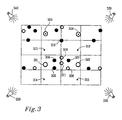
Fig. 3 illustrates a detailed view of a positioning pattern according to the present invention; -
Fig. 4 illustrates an application of the present invention; -
Fig. 5 illustrates another application of the present invention; -
Fig. 6 illustrates schematically in a block diagram a method according to the present invention; and -
Fig. 7 illustrates another embodiment of the present invention. - In
Fig. 1 , reference numeral 1 generally denotes a measuring device 1 as seen from a cross sectional view according to an embodiment of the present invention. The device 1 comprises animage acquiring device 3 positioned a distance away from anobject 2 of interest. The device 1 is enclosed in acasing 8 andelectrical connectors 9, and optionally acontrol interface 10. InFig. 1 the object of interest is ashaft 2 and the device 1 is mounted on theshaft 2 supported by twobearings image acquiring device 3 is mounted close to the surface of theobject 2 and the device 1 may be arranged in such a way as to form acavity 7 which may be essentially sealed in order to decrease the risk of allowing dirt or other disturbing factors to enter into thecavity 7.Fig. 1 a is a cross sectional view of the embodiment across la fromFig. 1b which is a side view of the embodiment. - Signals from the
image acquiring device 3 are transferred to aprocessing device 200, illustrated inFig. 2 , via aconnector 207, for image processing and signal conditioning in order to provide a signal or signals indicative of the position of theobject 2 to some external device connected to the processing device using aconnector 203. The processing device may include aprocessor 201, memory unit (or units) 202,image processing unit 204, andother units - The
processing device 200 may conveniently be situated within the measuring device it self or provided as an external stand alone device depending on application. - In the embodiment illustrated in
Fig.1 animage acquiring device 3 is used for obtaining the position of theobject 2, however, other sensor types may be utilized which are arranged to obtain positioning data, for instance a magnetic sensor acquiring positions of magnetic "points" on theobject 2. - Non-contacting sensor means may advantageously be utilized since part of the
object 2 is encapsulated within thecasing 8 of the measuring device 1; however, these types of sensors may be used even if there is no encapsulation. Therefore, there is a small amount of disturbances that can influence the reading, such as dirt, light, or stray magnetic fields. In one embodiment thecasing 8 is made of an electrically conducting material with magnetic shielding properties in order to reduce the risk of influencing a magnetic sensor measuring the position of theobject 2. Thepattern 4 andcamera 3 may be provided in an enclosure for reducing the risk of contamination from the external environment, for instance dirt or light. - However, the invention is not limited to non-contacting measurements of the object's 2 position, contacting sensors can also be used, including, but not limited to, slip rings, impedance measurements, voltage dividers, digital encoders, and capacitive measurements.
- Turning now to
Fig. 3 , a functional pattern is described comprisingnode points 301 to 304 andinformation points 305 to 311. Points may have different sizes and with different filling ratios and these configurations will have a functional effect when reading them with a reading device such as a camera. InFig. 3 virtual points 312-315 are also indicated, these are not markings that are present in the actual solution but may optionally be used for analysis purposes as reference points in the analysis algorithm. In order to read the points using a camera,illumination -
Node points 301 to 304 may be as aring dot Node points 301 to 304 are used for determining the position in the camera window and type of point for a certain application and the determination is made in two steps: a first step for detecting the node points and a second for determining the node points' position with higher accuracy. The reason for doing the analysis in two steps is to reduce the computational power needed at each certain time unit. The more accurate determining may be made using a symmetry analysis, a centre of gravity analysis or similar method to determine the center of the point, a so called centroid calculation. This centroid calculation, using for instance gradient analysis, is done in at least two directions in order to acquire information about position in at least two directions (and possibly also rotational dimensionality of the object). The node points need to be large enough to provide a suitable number of pixels to do analysis on. In order to increase the accuracy of the determination the node points are advantageously not filled but rings with or without a dot in the center. This provides the analysis method chosen with a gradient feature both on the outside and the inside of the node point which enhances the accuracy of the center of the node analysis. The dot in the center of the ring may be used for providing a directional feature of the pattern, i.e. it will be easier for the analysis system since it will acquire reference points (or lines) on regular basis. These types of dot provided rings may be used every fifth degree around the object or so. For instance one may use undotted rings on an "equatorial" line of pattern groups and on each "southern" and "northern" 5 degrees from the "equatorial" line of pattern groups node points are used with dotted rings. Other shapes of the points may be used, for instance rectangularly or elliptically shaped points (these may be used for providing another way of obtaining directional and rotational information; i.e. the ellipse has a built in directional behavior from the shape). Other shapes may include quadratic, triangularly or irregularly shaped forms. - Information points 305 to 311 groups are centered around one node point, between two node points or between four node points. The information points are used for determining the absolute position of the pattern group. The information points have advantageously a different size than the node points in order to distinguish them from the node points. They are often smaller since they are not used for determining the position of the pattern with respect to the camera window but are used for determining the absolute coordinate of the identified group with respect to the object containing the pattern. Also these smaller information points may be of different character: filled circles, rings, and non existent (the non-existence of a point also provides information, if the system knows that a certain geometrical area may comprise points). The analysis system determines the pattern group of the information points and determines the relative position to each other and type of point character. Since the system knows the number of information points used in the information pattern groups, the system may determine which type of points is present at each location and from this analysis determine the absolute position of that information pattern group. Using seven information points as in
Fig. 3 with these three different characters a very large number of unique combination are available which is sufficient for reasonable sized objects and chosen accuracy; however, it should be understood that a different number of information points may be used depending on application. Different shapes of the information points and/or node points may be utilized, the invention is not limited to round shapes but squares, triangles or any other geometrical shape (even irregular shapes) may be used. The size of the node and/or information points may be used for providing the points with different type of information and in such a case, the size may be determined from the area of each point. The size may then be used even for irregular shapes since each point may be determined by the number of pixels that build up an image of the point. Node and information points may be the same points, i.e. they need not be of different size, type or location as long as the system may use the pattern for determining location of the point on the object and a position relative the sensing device. In an application with curved surfaces, the pattern is applied in an angular system rather than in a Cartesian coordinate system; i.e. for instance every 5th degree of the objects perimeter for a spherical object instead of every 5 mm around the perimeter. In this way irregularities of the object may be compensated for. However, it should be understood by the person skilled in the art that the pattern may be applied in a Cartesian coordinate system manner with appropriate adjustments in the calibration and/or analysis of the acquired pattern even for a non flat surface, i.e. a curved surface. - The pattern may be applied with any suitable application technique depending on type of surface and object, e.g. laser markings, engraving, etching, hobbing, knurling, scribing, dying, ink jet techniques, applied directly on the object or on a film or any other suitable material in turn fixed to the object, and so on as understood by the person skilled in the art. For instance an injection-molded sleeve may be provided with pattern groups already at the production of the sleeve and the sleeve may in turn be applied to an object of interest.
- Points in the pattern group may have different depths and depth profiles in the material onto which the points are applied. This may be convenient for providing different contrast configurations. For instance a point with a conical narrowing depth wise will be seen by a camera as being darker than a point with a flat bottom surface. Also, the pattern may stand out from the object, for instance as cones sticking out from the material; this may be useful for instance for determining distance between the sensing device and the object.
- The pattern may advantageously be arranged depending on type of surface, for instance to be suited for either essentially flat surfaces or curved surfaces. The present invention is particularly suited for use on curved surfaces.
- The pattern may provide information about x and y position of the object as well as rotation or bending of the object in relation to the sensing device. By measuring the distance between two information or node points (or even between a node and information part) or the size of a code or node point it is also possible to determine the distance between the object and sensing device, i.e. the z position.
- In case of an image acquisition device as sensing device an algorithm is used to determine the type of pattern and the relative positions and filling grade of each point.
- Since each pattern group is unique, it is possible to determine the absolute position of the pattern (and thus the object onto which the pattern is fixed). An analysis based on symmetry has benefits in being quick and not so computational intense and therefore possible to use in low cost solutions. The pixel values obtained from the camera comprise for instance grey scale data (or they may be color coded if the actual node and/or information points comprise color data), e.g. values in a range between 0 and 255. The analysis comprise setting a threshold value for where the system determines that a pixel comprise a marking or not. This threshold is settable (software or hardware vise) and may be controlled according to ambient light or dirt on the object upon where the markings are set. If a pixel completely is filled by a marked point, it may be read for example as 40 and a pixel completely without a marking may be read for example as 180, a pixel only partly filled by a marking may for example read as 90, which would be below a threshold of 100 and therefore determined as comprising a marking. It is possible to use these partly filled pixels in the analysis to enhance the accuracy of the position determination. The analysis scans over all pixels received in a frame and determines any node and information points in the frame. It may be arranged to filter out points below or over a certain number of pixels since the node and information points have a known size in pixels; e.g. points below 5 or larger than 15 may be filtered out for an application where node points have a size in the camera frame of
ca 10 pixels and information points a size ofca 6 pixels. The present invention is not limited to the above exemplified values of grey scales and sizes of camera readings. This is very dependent on application and sought after accuracy of the system and may be varied in a wide range. For instance, in grey scale solutions, completely black may be represented by a 0 or a figure 255 and completely white with 255 or 0 accordingly. The pixel sizes of node and information points may be chosen to any other suitable value as understood by the person skilled in the art depending for instance on camera setting, application, and distance between the camera and the pattern. -
Fig. 4 illustrates schematically atorque measuring device 400 using the present invention. Using the patterns for acquiring position of an object it is possible to measure strains in theobject 402. This can be done by comparing two different positions of theobject 402 and measuring the relative position between them. If there is a deviation between them this can be a result of strain; this is true for instance for a torque present in ashaft 402 where the torque induces an angular shift in theshaft 402 between two different points in the longitudinal direction of theshaft 402. However, the accuracy of the measuring device is dependent on the spacing of the two measuring points; the longer the distance between the two points the larger angular deflection and thus the better accuracy. InFig. 4 , a single sensing device (e.g. an image acquiring device) is used measuring two separated patterns at the same time and in order to increase the angular deflection twosleeves side sleeve shaft 402. Any angular deviation at each of the fixation points will be transferred to eachsleeve free end sleeve fixed end Patterns 4 and 4' on thesleeves free end same sensing device 401. This type of solution has a benefit in that there is no need for calibration between a plurality of sensing devices, for instance timing characteristics that might be a problem if theshaft 402 is turning at speeds similar or higher than the sensing rate. For instance, in the case of image acquisition devices, the frame rate of the image acquisition device as compared to the turning speed of theshaft 402 will set the upper limit on the accuracy. However, for applications using sensing devices with high sensing rates or in applications where theobject 402 is moving at a speed below the sensing rate, a plurality of sensing devices can be used andsuch cases sleeves shaft 402. The system may also provide information about the translational position of theshaft 402 and/or bending of theshaft 402. By providing a camera (not shown) at a different angular position (e.g. 90 degrees away from the first camera 401) but at the same shaft longitudinal position, the system may operate as an X, Y, and Z positioning device as well as providing information about torque and bending. The system may also provide information about rotational speed of the shaft. -
Fig. 5 illustrates an embodiment of the present invention utilized on a ball or part of a ball like structure for use in for instance a computer interface device such as a track ball, or a robot arm interface for keeping track of the position of the robot arm, in a 3D digitizer for measuring and digitizing the form of a three dimensional object. A positioning system according to this embodiment comprises aball 501 with apattern 504 according to the present invention arranged on theball 501. Apattern detection system 503 comprising a computational unit (not shown) and e.g. acamera 502 detecting the position of the pattern with respect to the detection system and being able to output via an interface (not shown) images or absolute coordinates of theball 501, depending on if the system have a computational unit or not. Since the ball and the pattern may be made in a resilient material it can be used as a load bearing element. This will be discussed more in detail later on in this document. -
Fig. 6 is a schematic block diagram of a method (steps 601 to 605) for calibrating the measurement device according to the present invention. During application of the pattern on the object that one desire to know the position of one may calibrate the pattern; this may be done in a manufacturing rig where the object is fixed to in a rotatable manner (if the object is at least partly with a spherical or cylindrical geometry). The manufacturing rig may be equipped with a reference position determining device, such as an angular encoder for determination of the angular position of the object during rotation in the rig. The object may rotate while the pattern is applied thus ensuring that the pattern is applied in an angular manner (i.e. not according to a Cartesian coordinate system as explained earlier). In the same rig or at least in connection to the rig, a calibration system may be located, reading point values when rotating the object and obtaining angular measurement data from the reference position determining device. One may then obtain reference values of positions of the node points and correspondingly a calibration database may be created that may be used in devices using the present invention in order to further increase the accuracy of the measurements of the absolute position of the object in application. A similar calibration technique may be applied to the system on site for recalibration or when the system is applied to an existing application, e.g. a sleeve or film with the pattern group applied to a shaft already mounted in its proper application, it may these types of circumstances be of interest to calibrate the system in site. - The calibration method may comprise the following steps:
- mounting of the object in the calibration rig (601);
- obtaining pattern images of the pattern on the object (602);
- obtaining absolute position data from a separate position detector (603);
- associating the obtained pattern images with the absolute position of the object (604); and
- providing a calibration database for the calibrated object (605). The calibration database may comprise a simple data list of calibration data, i.e. pairs of reference calibration positions and points in the obtained pattern images, or an algorithm associating points in the pattern with absolute positions.
- Adjustment of thresholds and lighting conditions may be utilized by reading background areas (i.e. areas without any pixels in) for obtaining a current light condition. It is then possible to set a new threshold value between marked or unmarked pixels and also it is possible to adjust the intensity from the
illumination devices - Turning now to
Fig. 7 , illustrating an embodiment of the present invention of atorque measuring device 710, where twolines 4, 4' of pattern groupings are located on ashaft 702. Twocameras such line 4, 4' and relay either image information or position data to acentral processing device 730 viacables interface units - In another variation of above described
torque measuring device 710, the two cameras are reduced to one camera measuring on both patterns at the same time by relaying images to the camera from the two locations. This can be done by relaying the images using optical fibers, using mirrors, or a prism. - The camera may be an infrared sensitive camera detecting different temperatures in the object and the pattern on the object may be arranged with different temperature characteristics. Illumination in the infrared range may be provided in this type of solution in order to provide adequate illumination contrast and other parameters.
- The present invention of determining absolute positions on objects may be utilized in a number of applications since the camera and computational systems may comprise low cost devices. Applications range from such as for instance a torque meter measuring torque in a non contact manner, for use in vehicles measuring torque in a shaft in the drive line (for optimizing combustion processes or output power to each wheel) or in the steering wheel shaft (for use in power steering), in a bicycle (e.g. a spinning cycle used for exercise purposes), on any type of shaft where toque is of interest to measure. The invention may also be used for measuring other parameter related to a position of the object of interest, such parameters include, but are not limited to, force, rotational speed, position, and bending. The present invention may be used for instance also as a sensor for ABS (Automatic Break Systems) application, for anti spin sensors, or in CNC (computerized numerical control) machines in manufacturing for positioning the tool used in the CNC machine.
- A one camera solution measuring pattern groups on an object with only rotational translation will provide an accurate and low cost solution for determining the angular position of the object, for instance as an angular encoder but with a large increase in resolution. For instance where the object is a wheel like object, e.g. a disc with a thickness sufficient enough to provide space for the pattern, the pattern may be provided on the wheel outer circumference or on a side of the wheel.
- The present invention may be utilized in an articulating arm (for determining and digitizing the geometrical proportions of an object) by combining a number of different embodiments of the present invention. An articulating arm often comprises a number of joints, each with a position sensor for determining the position of each part comprising the arm. With a number of such angular joints the articulating arm can be used for determining the geometrical dimensions of the object and providing these to a computer aided design system (CAD) for obtaining the geometrical dimensions into a computational system. An articulating arm according to the present invention may comprise joints with a combination of 3D and 1 D sensing devices, for instance a first 1 D sensor located at the base of the arm, a second 1 D sensor in each 1 D joint between each arm section, and a 3D sensing device holding a probe used for determining the position of an test object under scrutiny of the articulating arm. The number and type of sensing devices forming part of the articulating arm may be varied in our configurations accomplishing the same functionality. The first 1 D sensing device keeps track of the overall rotational position of the arm with respect to the surface where upon the articulating arm arrangement stands on, the second and subsequent 1 D sensing devices in each joint between each arm section each keep track of a rotation position, and the 3D sensing device keeps track of the probe position relative the arm. Taking measurements from each sensing device into consideration the position of the probe relative the test object may be determined and the geometrical configuration of the test object digitized.
- The present invention may also be used in a theodolite which is an instrument for measuring both horizontal and vertical angles, for instance for use in triangulation applications. The theodolite comprises a telescope mounted in such a manner as to be movably within two perpendicular axes: a horizontal axis and a vertical axis. The theodolite is often mounted on a tripod placed precisely and vertically over the point to be measured and its vertical axis aligned with local gravity. The present invention may be used for acquiring absolute positioning data for the theodolite with respect to the environment, for instance the ground position where upon the theodolite is centered above. The sensing system may be arranged as an intermediate joint between a base plate of the tripod and the telescope. However, it should be understood by the person skilled in the art that other parts and enclosures may be provided in order to build up such a device, for instance mechanical adjustment knobs for mechanically calibrate the device to a suitable position with respect to gravity and/or planar to the ground, reading displays for a user to read position data, communication interface for communicating such data to an external device (e.g. a laptop computer), power supply (e.g. external power or internal battery power). The overall composition and function of theodolites are generally known by the person skilled in the art and will not be described in this document.
- One benefit of the present invention is that the pattern may be provided on load bearing elements in constructions of different applications wherein the invention may be applicable. For instance, in the case of a torque sensor, the pattern is provided on the shaft which in turn is part of the overall application wherein the shaft is located, in an articulating arm arrangement the pattern is provided on the elements taking up load forming the joints, in a bearing application the pattern may be provided on load bearing elements such as balls or cylinders forming part of ball or cylinder bearings. This benefit comes from the fact that the pattern may be provided either as part of the material of the object it self (such as dimples or indentations) or on a material resilient to mechanical wear attached to the object.
- Generally this invention also has a benefit of being able to provide high speed and highly accurate measurements of absolute position data, however, the upper limit of the speed is limited to the pattern acquisition rate, for instance in case of an image acquisition system providing images of the pattern, the frame rate of this image acquisition will set the upper limit on the rate. The present invention provide an accuracy that can exceed 10 fold the normal accuracy found in similar applications with more expensive and complex solutions in many applications.
- It should be noted that the word "comprising" does not exclude the presence of other elements or steps than those listed and the words "a" or "an" preceding an element do not exclude the presence of a plurality of such elements. It should further be noted that any reference signs do not limit the scope of the claims, that the invention may be implemented at least in part by means of both hardware and software, and that several "means", "units" or "devices" may be represented by the same item of hardware.
- The above mentioned and described embodiments are only given as examples and should not be limiting to the present invention. Other solutions, uses, objectives, and functions within the scope of the invention as claimed in the below described patent claims should be apparent for the person skilled in the art.
Claims (23)
- A position detecting system (1), for detecting a position of an object (2), the system comprising:- a pattern group (4) comprising at least one node point (301-304) and at least one Information point (305-311) and a plurality of said pattern groups being arranged directly or indirectly on said object (2);- at least one sensing device (3) for detecting said pattern (4); and- a computational device (200) comprising means for analysing signals for determining geometrical centre positions in at least two directions of node points (301-304) in said pattern group and determining type of point and position of information points located on said object (2) ; said node points (301-304) being arranged to provide a position relative said sensing device (3) and said information points (305-311) providing location of said node point relative to said object.
- The position detecting system (1) according to claim 1, wherein said object (2) is a three dimensional object (2).
- The position detecting system (1) according to any of claims 1 to 2, wherein said pattern group (4) is provided on a curved surface of said object (2).
- The position detecting system (1) according to any of claims 1 to 3, wherein two lines (4, 4') of pattern groups are located essentially parallel to each other at a distance (d) from each other In a longitudinal direction of a shaft (2).
- The position detecting system (1) according to claim 4, wherein two sensing devices (3) are provided, each reading one of said two lines (4, 4') of pattern groups.
- The position detecting system (1) according to any of claims 1 to 5, further comprising at least one illumination device (320, 330, 340, 350) and where the illumination is one of visible light, infrared light, x-ray light, ultraviolet light.
- The position detecting system (1) according to claim 6, wherein illumination intensity from said illumination device (320, 330, 340, 350) is controlled by said computational device (200).
- The position detecting system (1) according to any of claims 1 to 7, wherein said node points (301-304) and information points (305-311) comprise at least one of a filled circle, a ring, or a ring with a center marking.
- The position detecting system (1) according to any of claims 1 to 8, wherein at least one of said node points (301-304) and information points (305-311) are color coded.
- The position detecting system (1) according to any of claims 1 to 9, wherein said pattern group (4) and sensing device (3) are located in an enclosure providing protection from environmental parameters.
- The position detecting system(1) according to any of claims 1 to 10, wherein said computational device (200) is further arranged to determine the geometrical center positions of node points (301-304) using a vision based algorithm using gradient analysis.
- The position detecting system (1) according to any of claims 1 to 11, wherein the geometrical centre is determined for both node (301-304) and information points (305-311) of the pattern (4).
- The position detecting system (1) according to any of claims 1 to 12, wherein the node points (301-304) comprise a plurality of different types of points, for instance filled point, unfilled point, or unfilled point with a centre dot.
- The position detecting system (1) according to claim 12, wherein the point has a shape chosen from one of: circular, rectangular, quadratic, or triangular.
- The position detecting system (1) according to any of claims 1 to 14, wherein the information points comprise a plurality of different types of points, for Instance filled point, unfilled point, or unfilled point with a centre dot.
- The position detecting system (1) according to any of claims 1 to 15, wherein the computational device (200) Is arranged to determine a distance between the object (2) and the sensing device (3) by measuring at least one of the size of a node point (301-304), the size of an information point (305-311), the distance between two node points (301-304), the distance between two information points (305-311), and the distance between a node (301-304) and an information point(305-311).
- The position detecting system (1) according to any of claims 1 to 16, wherein the sensing device (3) is an image acquisition device (3).
- The position detecting system (1) according to claim 17, wherein the image acquisition device (3) is a camera.
- A torque sensor (400), for measuring a torque in an object (2), the sensor comprising:- a position detection system (1) according to claim 1;- at least two sleeves (403, 404), each with a plurality of said pattern groups (4, 4'), said sleeves mounted on said object (2); andwherein said position detection system (1) obtains position data from each sleeve (403, 404) and said computational device (200) further comprises means to detect an angular difference between the position of said sleeves (403, 404) and to determine a torque from said angular difference.
- A method for determining a position of an object (2), comprising the steps of:- detecting with a sensing device a pattern group (4) located on said object (2);- determining geometrical center positions in at least two directions of node points (301-304) in said pattern group (4) ;- determining type of node point (301-304);- determining type and position of information points (305-311) located on said object (2); and- determining absolute position of said object (2) relative said sensing device (3) using combined information of said position and type of points of both node (301-304) and information (305-311) points.
- A computer program stored in a computer readable medium encoding the method steps of claim 18 to be carried out on a computational device (200) using data received from a sensing device (3).
- The computer program according to claim 21, wherein geometrical center positions of node points (301-304) are determined using a vision based algorithm using gradient analysis.
- An angular detector for determining an angular position of an object (2), comprising:- a position detection system (1) according to claim 1,wherein said computational device (200) further comprises means for determining an angular position of said object (2) from said signal analysis.
Applications Claiming Priority (2)
| Application Number | Priority Date | Filing Date | Title |
|---|---|---|---|
| SE0502884 | 2005-12-23 | ||
| PCT/SE2006/001136 WO2007073272A1 (en) | 2005-12-23 | 2006-10-06 | Positioning pattern |
Publications (3)
| Publication Number | Publication Date |
|---|---|
| EP1963786A1 EP1963786A1 (en) | 2008-09-03 |
| EP1963786A4 EP1963786A4 (en) | 2012-02-15 |
| EP1963786B1 true EP1963786B1 (en) | 2013-07-24 |
Family
ID=38188907
Family Applications (1)
| Application Number | Title | Priority Date | Filing Date |
|---|---|---|---|
| EP06799736.1A Not-in-force EP1963786B1 (en) | 2005-12-23 | 2006-10-06 | Positioning pattern |
Country Status (10)
| Country | Link |
|---|---|
| US (1) | US7957931B2 (en) |
| EP (1) | EP1963786B1 (en) |
| JP (1) | JP5314428B2 (en) |
| CN (1) | CN101331384B (en) |
| AU (1) | AU2006327353B2 (en) |
| BR (1) | BRPI0620380B1 (en) |
| CA (1) | CA2634908C (en) |
| ES (1) | ES2431632T3 (en) |
| RU (1) | RU2431804C2 (en) |
| WO (1) | WO2007073272A1 (en) |
Cited By (1)
| Publication number | Priority date | Publication date | Assignee | Title |
|---|---|---|---|---|
| DE102015103941A1 (en) * | 2015-03-17 | 2016-09-22 | Nexustec Gmbh | Device and method for screwing objects |
Families Citing this family (27)
| Publication number | Priority date | Publication date | Assignee | Title |
|---|---|---|---|---|
| DE102006004197A1 (en) * | 2006-01-26 | 2007-08-09 | Klett, Rolf, Dr.Dr. | Method and device for recording body movements |
| JP4969279B2 (en) * | 2007-03-22 | 2012-07-04 | 本田技研工業株式会社 | Position detection method and position detection apparatus |
| RU2467284C2 (en) * | 2007-07-03 | 2012-11-20 | ДжиКоудер Системз АБ | Pretension monitoring |
| TWI349884B (en) * | 2007-11-14 | 2011-10-01 | Pixart Imaging Inc | Data encryption method implemented on a pattern displaying medium with at least two types of ink |
| US8736751B2 (en) * | 2008-08-26 | 2014-05-27 | Empire Technology Development Llc | Digital presenter for displaying image captured by camera with illumination system |
| CH702990A1 (en) * | 2010-04-23 | 2011-10-31 | Bmc Trading Ag | Device and method for measuring a force for exposure to a bicycle pedal axle. |
| TWI468655B (en) * | 2010-10-07 | 2015-01-11 | Hon Hai Prec Ind Co Ltd | System and method for monitoring temperature |
| JP5832088B2 (en) | 2010-12-15 | 2015-12-16 | キヤノン株式会社 | Rotary encoder |
| CN103890754B (en) * | 2011-08-24 | 2016-12-14 | 谷歌公司 | The system and method that data in font file are compressed |
| EA020939B1 (en) * | 2012-05-31 | 2015-02-27 | Закрытое акционерное общество научно-исследовательская производственная компания "Электрон" (ЗАО НИПК "Электрон") | METHOD FOR DETERMINING GEOMETRIC DISPLACEMENTS OF SENSORS IN THE PLANE DETECTOR OF X-RAY IMAGE |
| KR101398068B1 (en) | 2012-09-17 | 2014-05-27 | 주식회사 이미지넥스트 | Vehicle Installed Camera Extrinsic Parameter Estimation Method and Apparatus |
| CN103644860B (en) * | 2013-12-09 | 2016-06-22 | 二重集团(德阳)重型装备股份有限公司 | Large space free curved face measurement method |
| US9684837B2 (en) * | 2014-02-24 | 2017-06-20 | Nissan Motor Co., Ltd. | Self-location calculating device and self-location calculating method |
| BR112016018603B1 (en) * | 2014-02-24 | 2022-01-04 | Nissan Motor Co. Ltd | EQUIPMENT FOR CALCULATING OWN POSITION AND PROCESS FOR CALCULATING OWN POSITION |
| US10190891B1 (en) * | 2014-07-16 | 2019-01-29 | Apple Inc. | Optical encoder for detecting rotational and axial movement |
| RU2015113949A (en) * | 2015-04-16 | 2016-11-10 | Общество с ограниченной ответственностью "Лаборатория 24" | TEACHING METHOD AND MEANS FOR ITS IMPLEMENTATION |
| EP3159829A1 (en) * | 2015-10-21 | 2017-04-26 | Thomson Licensing | Methods of detecting and managing a fiducial marker displayed on a display device |
| CN105866149B (en) * | 2016-04-08 | 2018-04-10 | 中国工程物理研究院核物理与化学研究所 | The localization method of one species elliposoidal component |
| US10190947B2 (en) * | 2016-12-01 | 2019-01-29 | General Electric Company | Visual creep inspection of rotating components |
| US11263779B2 (en) | 2017-06-20 | 2022-03-01 | Hewlett-Packard Development Company, L.P. | Sensors positions determinations |
| US11105613B2 (en) * | 2017-08-07 | 2021-08-31 | DePuy Synthes Products, Inc. | Universal direct measurement depth gauge |
| US10247542B2 (en) | 2017-08-09 | 2019-04-02 | Leica Geosystems Ag | Handheld measuring aid with a 3-axis joint connection and a spherical encoder |
| RU2685808C1 (en) * | 2018-07-31 | 2019-04-23 | Общество с ограниченной ответственностью "Торговый дом "Технолайн" (ООО"Торговый дом"Технолайн") | Method and apparatus for training multiplication table and self-testing knowledge of multiplication table using augmented reality elements and graphical carrier for generating thereof |
| CN109297409B (en) * | 2018-10-23 | 2020-07-21 | 深圳市万福达精密设备股份有限公司 | Battery displacement identification and positioning device and method |
| CN110031014B (en) * | 2019-03-27 | 2024-01-26 | 浙江亚特电器股份有限公司 | Visual positioning method based on pattern recognition |
| EP3719696A1 (en) * | 2019-04-04 | 2020-10-07 | Aptiv Technologies Limited | Method and device for localizing a sensor in a vehicle |
| US12469437B2 (en) | 2021-09-17 | 2025-11-11 | Google Llc | Encoding and recognizing positions of a display |
Family Cites Families (82)
| Publication number | Priority date | Publication date | Assignee | Title |
|---|---|---|---|---|
| US568570A (en) * | 1896-09-29 | Brake mechanism for electric elevators | ||
| US4867973A (en) * | 1984-08-31 | 1989-09-19 | Cytogen Corporation | Antibody-therapeutic agent conjugates |
| JPS6361903A (en) * | 1986-09-03 | 1988-03-18 | Nissan Motor Co Ltd | Three-dimensional coordinate converting device |
| US6018026A (en) * | 1988-01-22 | 2000-01-25 | Zymogenetics, Inc. | Biologically active dimerized and multimerized polypeptide fusions |
| US5567584A (en) * | 1988-01-22 | 1996-10-22 | Zymogenetics, Inc. | Methods of using biologically active dimerized polypeptide fusions to detect PDGF |
| KR900702328A (en) * | 1988-07-12 | 1990-12-06 | 후루노 기요까따 | Rotary encoder |
| SE9201073D0 (en) * | 1992-04-03 | 1992-04-03 | Kabi Pharmacia Ab | PROTEIN FORMULATION |
| US5319577A (en) * | 1992-12-18 | 1994-06-07 | Georgia Tech Research Corporation | Orientation sensing system and method for a spherical body |
| JP3262297B2 (en) * | 1993-04-27 | 2002-03-04 | 株式会社ワコム | Optical coordinate input device |
| JP3277052B2 (en) * | 1993-11-19 | 2002-04-22 | シャープ株式会社 | Coordinate input device and coordinate input method |
| US6172665B1 (en) * | 1994-11-14 | 2001-01-09 | Edward T. Bullister | Mouse and trackball with optimal measurement optics |
| US5656261A (en) * | 1995-01-18 | 1997-08-12 | The Picower Institute For Medical Research | Preventing and reversing advanced glycosylation endproducts |
| EP0808163B1 (en) * | 1995-01-18 | 2003-07-23 | Alteon, Inc. | Use of thiazolium compounds for preventing and reversing the formation of advanced glycosylation endproducts |
| NO315930B1 (en) * | 1995-01-18 | 2003-11-17 | Picower Inst For Medical Res T | Use of Thiazolium Compounds in the Preparation of Pharmaceutical Preparations, Compounds Containing the Compounds, and Nyetiazolium Compounds |
| US5920307A (en) * | 1995-02-21 | 1999-07-06 | Lucent Technologies, Inc. | System for directly sensing the orientation of a track ball |
| WO1996031537A1 (en) * | 1995-04-05 | 1996-10-10 | The Picower Institute For Medical Research | Agents for binding to advanced glycosylation endproducts, and methods of their use |
| US5747035A (en) * | 1995-04-14 | 1998-05-05 | Genentech, Inc. | Polypeptides with increased half-life for use in treating disorders involving the LFA-1 receptor |
| US5864018A (en) * | 1996-04-16 | 1999-01-26 | Schering Aktiengesellschaft | Antibodies to advanced glycosylation end-product receptor polypeptides and uses therefor |
| US6790443B2 (en) * | 1996-11-22 | 2004-09-14 | The Trustees Of Columbia University In The City Of New York | Method for treating symptoms of diabetes |
| US7258857B2 (en) * | 1996-11-22 | 2007-08-21 | The Trustees Of Columbia University In The City Of New York | Rage-related methods for treating inflammation |
| US6555651B2 (en) * | 1997-10-09 | 2003-04-29 | The Trustees Of Columbia University In The City Of New York | Ligand binding site of rage and uses thereof |
| US7081241B1 (en) * | 1998-10-06 | 2006-07-25 | The Trustees Of Columbia University In The City Of New York | Extracellular rage binding protein (EN-RAGE) and uses thereof |
| JPH10232242A (en) * | 1997-02-19 | 1998-09-02 | Mitsubishi Electric Corp | Detector |
| US5965879A (en) * | 1997-05-07 | 1999-10-12 | The United States Of America As Represented By The Administrator Of The National Aeronautics And Space Administration | Method and apparatus for ultra-high-sensitivity, incremental and absolute optical encoding |
| US7101838B2 (en) * | 1997-08-05 | 2006-09-05 | The Trustees Of Columbia University In The City Of New York | Method to prevent accelerated atherosclerosis using (sRAGE) soluble receptor for advanced glycation endproducts |
| MY131805A (en) * | 1997-09-18 | 2007-09-28 | Biogen Idec Inc | Synergistic composition and methods for treating neoplastic or cancerous growths and for restoring or boosting hematopoiesis. |
| US6380165B1 (en) * | 1997-09-19 | 2002-04-30 | The Picower Institute For Medical Research | Immunological advanced glycation endproduct crosslink |
| US6761888B1 (en) * | 2000-05-26 | 2004-07-13 | Neuralab Limited | Passive immunization treatment of Alzheimer's disease |
| US6167958B1 (en) * | 1998-01-29 | 2001-01-02 | Baker Hughes Incorporated | Cutting matrix and method of applying the same |
| US6323218B1 (en) * | 1998-03-11 | 2001-11-27 | The General Hospital Corporation | Agents for use in the treatment of Alzheimer's disease |
| US6465422B1 (en) * | 1998-04-17 | 2002-10-15 | The Trustees Of Columbia University In The City Of New York | Method for inhibiting tumor invasion or spreading in a subject |
| US6753150B2 (en) * | 1998-10-05 | 2004-06-22 | The Trustees Of Columbia University In The City Of New York | Method for determining whether a compound is capable of inhibiting the interaction of a peptide with rage |
| AU765719B2 (en) * | 1998-10-06 | 2003-09-25 | Trustees Of Columbia University In The City Of New York, The | Extracellular novel rage binding protein (EN-RAGE) and uses thereof |
| US6197294B1 (en) * | 1998-10-26 | 2001-03-06 | Neurotech S.A. | Cell surface molecule-induced macrophage activation |
| JP3458737B2 (en) * | 1998-11-27 | 2003-10-20 | 株式会社デンソー | Reading method of two-dimensional code and recording medium |
| US6605642B2 (en) * | 1999-04-05 | 2003-08-12 | City Of Hope | Inhibitors of formation of advanced glycation endproducts (AGES) |
| US6787566B2 (en) * | 1999-04-05 | 2004-09-07 | City Of Hope | Breakers of advanced glycation endproducts |
| US6939545B2 (en) * | 1999-04-28 | 2005-09-06 | Genetics Institute, Llc | Composition and method for treating inflammatory disorders |
| JP2003507013A (en) * | 1999-08-13 | 2003-02-25 | ザ・トラスティーズ・オブ・コランビア・ユニバーシティー・イン・ザ・シティー・オブ・ニューヨーク | Method for inhibiting the binding of β-sheet fibril to RAGE and its result |
| US20050170382A1 (en) * | 1999-10-06 | 2005-08-04 | The Trustees Of Columbia University In The City Of New York. | RAGE-related compositions |
| CA2382165A1 (en) * | 1999-12-08 | 2001-06-14 | Genset S.A. | Full-length human cdnas encoding potentially secreted proteins |
| WO2001065225A2 (en) * | 2000-03-02 | 2001-09-07 | Siemens Automotive Corporation | Engine torque sensor |
| JP3920641B2 (en) * | 2000-04-14 | 2007-05-30 | ナイアダイン コーポレーション | Method for identifying modulators of protein-late saccharification reaction product (protein-AGE) formation |
| JP4187901B2 (en) * | 2000-04-19 | 2008-11-26 | Sriスポーツ株式会社 | Method and apparatus for measuring rotational motion of a sphere |
| US6825164B1 (en) * | 2000-08-14 | 2004-11-30 | The Trustees Of Columbia University In The City Of New York | Method to increase cerebral blood flow in amyloid angiopathy |
| US6563015B1 (en) * | 2000-08-14 | 2003-05-13 | The Trustees Of Columbia University In The City Of New York | Transgenic mice over-expressing receptor for advanced glycation endproduct (RAGE) and mutant APP in brain and uses thereof |
| JP2002081925A (en) * | 2000-09-06 | 2002-03-22 | Seiko Epson Corp | Driving device for spherical phase, phase detecting method, and information recording medium |
| JP4282216B2 (en) * | 2000-09-19 | 2009-06-17 | オリンパス株式会社 | 3D position and orientation sensing device |
| WO2002029091A2 (en) * | 2000-10-02 | 2002-04-11 | Reddy Us Therapeutics, Inc. | Methods and compositions for the treatment of inflammatory diseases |
| AU2002213192A1 (en) * | 2000-10-13 | 2002-04-22 | The Trustees Of Columbia University In The City Of New York | A method for inhibiting new tissue growth in blood vessels in a patient subjected to blood vessel injury |
| JP4776832B2 (en) * | 2000-10-19 | 2011-09-21 | キヤノン株式会社 | Coordinate input device and coordinate plate of image input device |
| US20050244849A1 (en) * | 2000-12-15 | 2005-11-03 | Genetics Institute, Llc | Screening assays for rheumatoid arthritis |
| PL366250A1 (en) * | 2000-12-29 | 2005-01-24 | Reddy Us Therapeutics, Inc. | Detection of compounds that modulate inflammatory responses |
| PL362324A1 (en) * | 2001-02-19 | 2004-10-18 | Merck Patent Gmbh | Artificial fusion proteins with reduced immunogenicity |
| JP3837494B2 (en) * | 2001-03-19 | 2006-10-25 | 国立大学法人金沢大学 | Soluble RAGE protein |
| JP4778156B2 (en) * | 2001-03-23 | 2011-09-21 | オリンパス株式会社 | Distance information acquisition apparatus or system, pattern projection apparatus, and distance information acquisition method |
| US6765195B1 (en) * | 2001-05-22 | 2004-07-20 | The United States Of America As Represented By The Administrator Of The National Aeronautics And Space Administration | Method and apparatus for two-dimensional absolute optical encoding |
| JP2003014459A (en) * | 2001-07-03 | 2003-01-15 | Sony Corp | Direction detecting device, direction detecting method, walking detecting device |
| US6605628B1 (en) * | 2001-08-24 | 2003-08-12 | Wyeth Holdings Corporation | Method of using 5-(arysulfonyl)-, 5-(arylsulfanyl)-and 5-(arylsulfanyl)thiazolidine-2,4-diones for inhibition of farnesyl-protein transferase |
| JP4056891B2 (en) * | 2002-01-18 | 2008-03-05 | 日本電信電話株式会社 | Three-dimensional position / attitude detection device, method, program, and recording medium |
| EP1476724A1 (en) * | 2002-02-08 | 2004-11-17 | Robert Bosch Gmbh | Optical angle and torque sensor |
| JP2004015965A (en) * | 2002-06-10 | 2004-01-15 | Ricoh Co Ltd | Spherical motor |
| MXPA05001758A (en) * | 2002-08-16 | 2005-08-19 | Wyeth Corp | Compositions and methods for treating rage-associated disorders. |
| JP4109094B2 (en) * | 2002-12-03 | 2008-06-25 | Sriスポーツ株式会社 | Method for measuring the rotational and flight characteristics of a sphere |
| US8067371B2 (en) * | 2003-05-09 | 2011-11-29 | The Trustees Of Columbia University In The City Of New York | RAGE G82S-related methods and compositions for treating inflammatory disorders |
| WO2005021710A2 (en) * | 2003-06-02 | 2005-03-10 | University Of Miami | Chimeric molecules and methods of use |
| CN1874782A (en) * | 2003-09-05 | 2006-12-06 | 纽约市哥伦比亚大学信托人 | RAGE-related methods and compositions for treating glomerular injury |
| JP4502361B2 (en) * | 2003-09-30 | 2010-07-14 | キヤノン株式会社 | Index attitude detection method and apparatus |
| WO2005042032A1 (en) * | 2003-10-31 | 2005-05-12 | The Trustees Of Columbia University In The City Of New York | Methods for treating multiple sclerosis |
| JP2005181155A (en) * | 2003-12-19 | 2005-07-07 | Sony Corp | Inspection and measurement apparatus and inspection and measurement method for inspection and measurement object |
| JP2005257463A (en) * | 2004-03-11 | 2005-09-22 | Sony Corp | Position detection system |
| JP4322837B2 (en) * | 2004-03-31 | 2009-09-02 | 富士フイルム株式会社 | Exposure apparatus calibration method, exposure method, and exposure apparatus |
| JP4533090B2 (en) * | 2004-05-14 | 2010-08-25 | キヤノン株式会社 | Index calibration apparatus and information processing method |
| US20060012414A1 (en) * | 2004-07-15 | 2006-01-19 | Texas Instruments Incorporated | Circuit and method for generating a polyphase clock signal and system incorporating the same |
| WO2006012415A2 (en) * | 2004-07-20 | 2006-02-02 | Critical Therapeutics, Inc. | Rage protein derivatives |
| ES2473587T3 (en) * | 2004-08-03 | 2014-07-07 | Transtech Pharma, Inc. | RAGE fusion proteins and methods of use |
| EP1776459A1 (en) * | 2004-08-03 | 2007-04-25 | Transtech Pharma, Inc. | Rage fusion proteins and methods of use |
| EP1799700A4 (en) * | 2004-09-27 | 2009-02-11 | Centocor Inc | Srage mimetibody, compositions, methods and uses |
| US20080207499A1 (en) * | 2005-06-29 | 2008-08-28 | Gaetano Barile | Rage-related methods for treating and preventing diabetic retinopathy |
| WO2007094926A2 (en) * | 2006-02-09 | 2007-08-23 | Transtech Pharma, Inc. | Rage fusion proteins and methods of use |
| EA017291B1 (en) * | 2006-05-05 | 2012-11-30 | Транстек Фарма, Инк. | Rage fusion proteins, formulations, and methods of use thereof |
| WO2008100470A2 (en) * | 2007-02-15 | 2008-08-21 | Transtech Pharma, Inc. | Rage - immunoglobulin fusion proteins |
-
2006
- 2006-10-06 EP EP06799736.1A patent/EP1963786B1/en not_active Not-in-force
- 2006-10-06 CA CA2634908A patent/CA2634908C/en not_active Expired - Fee Related
- 2006-10-06 BR BRPI0620380-9A patent/BRPI0620380B1/en not_active IP Right Cessation
- 2006-10-06 WO PCT/SE2006/001136 patent/WO2007073272A1/en not_active Ceased
- 2006-10-06 JP JP2008547154A patent/JP5314428B2/en not_active Expired - Fee Related
- 2006-10-06 CN CN2006800475432A patent/CN101331384B/en not_active Expired - Fee Related
- 2006-10-06 AU AU2006327353A patent/AU2006327353B2/en not_active Ceased
- 2006-10-06 US US12/158,748 patent/US7957931B2/en not_active Expired - Fee Related
- 2006-10-06 RU RU2008130404/28A patent/RU2431804C2/en not_active IP Right Cessation
- 2006-10-06 ES ES06799736T patent/ES2431632T3/en active Active
Cited By (2)
| Publication number | Priority date | Publication date | Assignee | Title |
|---|---|---|---|---|
| DE102015103941A1 (en) * | 2015-03-17 | 2016-09-22 | Nexustec Gmbh | Device and method for screwing objects |
| WO2016146705A1 (en) | 2015-03-17 | 2016-09-22 | Nexustec Gmbh | Device and method for screwing objects |
Also Published As
| Publication number | Publication date |
|---|---|
| AU2006327353A1 (en) | 2007-06-28 |
| CA2634908A1 (en) | 2007-06-28 |
| HK1122095A1 (en) | 2009-05-08 |
| JP5314428B2 (en) | 2013-10-16 |
| ES2431632T3 (en) | 2013-11-27 |
| AU2006327353B2 (en) | 2011-11-24 |
| BRPI0620380A2 (en) | 2011-11-08 |
| RU2431804C2 (en) | 2011-10-20 |
| US7957931B2 (en) | 2011-06-07 |
| JP2009521671A (en) | 2009-06-04 |
| EP1963786A4 (en) | 2012-02-15 |
| CN101331384A (en) | 2008-12-24 |
| EP1963786A1 (en) | 2008-09-03 |
| CA2634908C (en) | 2015-05-19 |
| WO2007073272A1 (en) | 2007-06-28 |
| CN101331384B (en) | 2011-11-09 |
| RU2008130404A (en) | 2010-01-27 |
| BRPI0620380B1 (en) | 2018-04-24 |
| US20090177416A1 (en) | 2009-07-09 |
Similar Documents
| Publication | Publication Date | Title |
|---|---|---|
| CA2634908C (en) | Positioning pattern | |
| KR101108602B1 (en) | Vehicle wheel alignment system and methodology | |
| CN100335860C (en) | Workpiece inspection method | |
| CN104380038B (en) | Improved method and device for wheel alignment system rotation deflection compensation | |
| US10302407B2 (en) | Motorized orientable head for measuring system | |
| JP2009532685A (en) | Method and system for measuring shape of reflecting surface | |
| US20240369346A1 (en) | Method and System for High-precision Localization of Surface of Object | |
| CN101084413A (en) | Position measurement | |
| CN109032070A (en) | A kind of contactless R-test measuring instrument scaling method using eddy current displacement sensor | |
| CN101561251A (en) | Phase target-based optical three-coordinate measuring method | |
| CN101825460A (en) | Levelness detecting device | |
| CN111256592A (en) | External parameter calibration device and method for structured light sensor | |
| CN106168464A (en) | A kind of main shaft dynamic rotation method for testing precision based on machine vision | |
| CN107702738B (en) | Corner identifier, corner error calibration system and method | |
| CA2425377C (en) | Process for determining the alignment of a cylindrical body with respect to a reference direction | |
| Zexiao et al. | A novel approach for the field calibration of line structured-light sensors | |
| US20080123110A1 (en) | Multifaceted digitizer adapter | |
| CN118091223B (en) | Current sensor, current measurement method, apparatus, and storage medium | |
| CN118999470A (en) | Photoelectric earth surveying instrument | |
| HK1122095B (en) | Positioning pattern | |
| CN109062138A (en) | A kind of five shaft platform system calibrating schemes based on stereo calibration block | |
| Yang et al. | Measurement and evaluation of the wearing condition of the tire tread | |
| Jin et al. | Preliminary study on the measurement system for LAMOST small focal plane fiber positioning system | |
| CN102853997A (en) | Method and system for calibrating radiation heterogeneity of integrating sphere light source | |
| KR100617602B1 (en) | Pose Measurement System of Contactless 3-axis Simulator |
Legal Events
| Date | Code | Title | Description |
|---|---|---|---|
| PUAI | Public reference made under article 153(3) epc to a published international application that has entered the european phase |
Free format text: ORIGINAL CODE: 0009012 |
|
| 17P | Request for examination filed |
Effective date: 20080702 |
|
| AK | Designated contracting states |
Kind code of ref document: A1 Designated state(s): AT BE BG CH CY CZ DE DK EE ES FI FR GB GR HU IE IS IT LI LT LU LV MC NL PL PT RO SE SI SK TR |
|
| A4 | Supplementary search report drawn up and despatched |
Effective date: 20120116 |
|
| RIC1 | Information provided on ipc code assigned before grant |
Ipc: G01D 5/00 20060101AFI20120110BHEP Ipc: G01D 5/347 20060101ALI20120110BHEP Ipc: G01L 3/12 20060101ALI20120110BHEP Ipc: G06F 3/033 20060101ALI20120110BHEP Ipc: G06F 3/03 20060101ALI20120110BHEP |
|
| 17Q | First examination report despatched |
Effective date: 20120511 |
|
| DAX | Request for extension of the european patent (deleted) | ||
| GRAP | Despatch of communication of intention to grant a patent |
Free format text: ORIGINAL CODE: EPIDOSNIGR1 |
|
| GRAS | Grant fee paid |
Free format text: ORIGINAL CODE: EPIDOSNIGR3 |
|
| GRAA | (expected) grant |
Free format text: ORIGINAL CODE: 0009210 |
|
| AK | Designated contracting states |
Kind code of ref document: B1 Designated state(s): AT BE BG CH CY CZ DE DK EE ES FI FR GB GR HU IE IS IT LI LT LU LV MC NL PL PT RO SE SI SK TR |
|
| REG | Reference to a national code |
Ref country code: GB Ref legal event code: FG4D |
|
| REG | Reference to a national code |
Ref country code: CH Ref legal event code: EP |
|
| REG | Reference to a national code |
Ref country code: AT Ref legal event code: REF Ref document number: 623695 Country of ref document: AT Kind code of ref document: T Effective date: 20130815 |
|
| REG | Reference to a national code |
Ref country code: IE Ref legal event code: FG4D |
|
| REG | Reference to a national code |
Ref country code: DE Ref legal event code: R096 Ref document number: 602006037535 Country of ref document: DE Effective date: 20130919 |
|
| REG | Reference to a national code |
Ref country code: CH Ref legal event code: NV Representative=s name: BUGNION S.A., CH |
|
| REG | Reference to a national code |
Ref country code: ES Ref legal event code: FG2A Ref document number: 2431632 Country of ref document: ES Kind code of ref document: T3 Effective date: 20131127 |
|
| REG | Reference to a national code |
Ref country code: AT Ref legal event code: MK05 Ref document number: 623695 Country of ref document: AT Kind code of ref document: T Effective date: 20130724 |
|
| REG | Reference to a national code |
Ref country code: NL Ref legal event code: VDEP Effective date: 20130724 |
|
| REG | Reference to a national code |
Ref country code: LT Ref legal event code: MG4D |
|
| PG25 | Lapsed in a contracting state [announced via postgrant information from national office to epo] |
Ref country code: SE Free format text: LAPSE BECAUSE OF FAILURE TO SUBMIT A TRANSLATION OF THE DESCRIPTION OR TO PAY THE FEE WITHIN THE PRESCRIBED TIME-LIMIT Effective date: 20130724 Ref country code: LT Free format text: LAPSE BECAUSE OF FAILURE TO SUBMIT A TRANSLATION OF THE DESCRIPTION OR TO PAY THE FEE WITHIN THE PRESCRIBED TIME-LIMIT Effective date: 20130724 Ref country code: PT Free format text: LAPSE BECAUSE OF FAILURE TO SUBMIT A TRANSLATION OF THE DESCRIPTION OR TO PAY THE FEE WITHIN THE PRESCRIBED TIME-LIMIT Effective date: 20131125 Ref country code: BE Free format text: LAPSE BECAUSE OF FAILURE TO SUBMIT A TRANSLATION OF THE DESCRIPTION OR TO PAY THE FEE WITHIN THE PRESCRIBED TIME-LIMIT Effective date: 20130724 Ref country code: IS Free format text: LAPSE BECAUSE OF FAILURE TO SUBMIT A TRANSLATION OF THE DESCRIPTION OR TO PAY THE FEE WITHIN THE PRESCRIBED TIME-LIMIT Effective date: 20131124 Ref country code: AT Free format text: LAPSE BECAUSE OF FAILURE TO SUBMIT A TRANSLATION OF THE DESCRIPTION OR TO PAY THE FEE WITHIN THE PRESCRIBED TIME-LIMIT Effective date: 20130724 Ref country code: CY Free format text: LAPSE BECAUSE OF FAILURE TO SUBMIT A TRANSLATION OF THE DESCRIPTION OR TO PAY THE FEE WITHIN THE PRESCRIBED TIME-LIMIT Effective date: 20130626 |
|
| PG25 | Lapsed in a contracting state [announced via postgrant information from national office to epo] |
Ref country code: LV Free format text: LAPSE BECAUSE OF FAILURE TO SUBMIT A TRANSLATION OF THE DESCRIPTION OR TO PAY THE FEE WITHIN THE PRESCRIBED TIME-LIMIT Effective date: 20130724 Ref country code: FI Free format text: LAPSE BECAUSE OF FAILURE TO SUBMIT A TRANSLATION OF THE DESCRIPTION OR TO PAY THE FEE WITHIN THE PRESCRIBED TIME-LIMIT Effective date: 20130724 Ref country code: NL Free format text: LAPSE BECAUSE OF FAILURE TO SUBMIT A TRANSLATION OF THE DESCRIPTION OR TO PAY THE FEE WITHIN THE PRESCRIBED TIME-LIMIT Effective date: 20130724 Ref country code: SI Free format text: LAPSE BECAUSE OF FAILURE TO SUBMIT A TRANSLATION OF THE DESCRIPTION OR TO PAY THE FEE WITHIN THE PRESCRIBED TIME-LIMIT Effective date: 20130724 Ref country code: PL Free format text: LAPSE BECAUSE OF FAILURE TO SUBMIT A TRANSLATION OF THE DESCRIPTION OR TO PAY THE FEE WITHIN THE PRESCRIBED TIME-LIMIT Effective date: 20130724 Ref country code: GR Free format text: LAPSE BECAUSE OF FAILURE TO SUBMIT A TRANSLATION OF THE DESCRIPTION OR TO PAY THE FEE WITHIN THE PRESCRIBED TIME-LIMIT Effective date: 20131025 |
|
| PG25 | Lapsed in a contracting state [announced via postgrant information from national office to epo] |
Ref country code: CY Free format text: LAPSE BECAUSE OF FAILURE TO SUBMIT A TRANSLATION OF THE DESCRIPTION OR TO PAY THE FEE WITHIN THE PRESCRIBED TIME-LIMIT Effective date: 20130724 |
|
| PG25 | Lapsed in a contracting state [announced via postgrant information from national office to epo] |
Ref country code: CZ Free format text: LAPSE BECAUSE OF FAILURE TO SUBMIT A TRANSLATION OF THE DESCRIPTION OR TO PAY THE FEE WITHIN THE PRESCRIBED TIME-LIMIT Effective date: 20130724 Ref country code: EE Free format text: LAPSE BECAUSE OF FAILURE TO SUBMIT A TRANSLATION OF THE DESCRIPTION OR TO PAY THE FEE WITHIN THE PRESCRIBED TIME-LIMIT Effective date: 20130724 Ref country code: SK Free format text: LAPSE BECAUSE OF FAILURE TO SUBMIT A TRANSLATION OF THE DESCRIPTION OR TO PAY THE FEE WITHIN THE PRESCRIBED TIME-LIMIT Effective date: 20130724 Ref country code: DK Free format text: LAPSE BECAUSE OF FAILURE TO SUBMIT A TRANSLATION OF THE DESCRIPTION OR TO PAY THE FEE WITHIN THE PRESCRIBED TIME-LIMIT Effective date: 20130724 Ref country code: RO Free format text: LAPSE BECAUSE OF FAILURE TO SUBMIT A TRANSLATION OF THE DESCRIPTION OR TO PAY THE FEE WITHIN THE PRESCRIBED TIME-LIMIT Effective date: 20130724 |
|
| PG25 | Lapsed in a contracting state [announced via postgrant information from national office to epo] |
Ref country code: MC Free format text: LAPSE BECAUSE OF FAILURE TO SUBMIT A TRANSLATION OF THE DESCRIPTION OR TO PAY THE FEE WITHIN THE PRESCRIBED TIME-LIMIT Effective date: 20130724 Ref country code: IT Free format text: LAPSE BECAUSE OF FAILURE TO SUBMIT A TRANSLATION OF THE DESCRIPTION OR TO PAY THE FEE WITHIN THE PRESCRIBED TIME-LIMIT Effective date: 20130724 |
|
| PLBE | No opposition filed within time limit |
Free format text: ORIGINAL CODE: 0009261 |
|
| STAA | Information on the status of an ep patent application or granted ep patent |
Free format text: STATUS: NO OPPOSITION FILED WITHIN TIME LIMIT |
|
| 26N | No opposition filed |
Effective date: 20140425 |
|
| REG | Reference to a national code |
Ref country code: IE Ref legal event code: MM4A |
|
| REG | Reference to a national code |
Ref country code: DE Ref legal event code: R097 Ref document number: 602006037535 Country of ref document: DE Effective date: 20140425 |
|
| PG25 | Lapsed in a contracting state [announced via postgrant information from national office to epo] |
Ref country code: IE Free format text: LAPSE BECAUSE OF NON-PAYMENT OF DUE FEES Effective date: 20131006 |
|
| PG25 | Lapsed in a contracting state [announced via postgrant information from national office to epo] |
Ref country code: TR Free format text: LAPSE BECAUSE OF FAILURE TO SUBMIT A TRANSLATION OF THE DESCRIPTION OR TO PAY THE FEE WITHIN THE PRESCRIBED TIME-LIMIT Effective date: 20130724 |
|
| PG25 | Lapsed in a contracting state [announced via postgrant information from national office to epo] |
Ref country code: LU Free format text: LAPSE BECAUSE OF NON-PAYMENT OF DUE FEES Effective date: 20131006 Ref country code: BG Free format text: LAPSE BECAUSE OF FAILURE TO SUBMIT A TRANSLATION OF THE DESCRIPTION OR TO PAY THE FEE WITHIN THE PRESCRIBED TIME-LIMIT Effective date: 20130724 Ref country code: HU Free format text: LAPSE BECAUSE OF FAILURE TO SUBMIT A TRANSLATION OF THE DESCRIPTION OR TO PAY THE FEE WITHIN THE PRESCRIBED TIME-LIMIT; INVALID AB INITIO Effective date: 20061006 |
|
| REG | Reference to a national code |
Ref country code: FR Ref legal event code: PLFP Year of fee payment: 10 |
|
| PGFP | Annual fee paid to national office [announced via postgrant information from national office to epo] |
Ref country code: CH Payment date: 20151021 Year of fee payment: 10 |
|
| PGFP | Annual fee paid to national office [announced via postgrant information from national office to epo] |
Ref country code: ES Payment date: 20151028 Year of fee payment: 10 |
|
| REG | Reference to a national code |
Ref country code: FR Ref legal event code: PLFP Year of fee payment: 11 |
|
| PGFP | Annual fee paid to national office [announced via postgrant information from national office to epo] |
Ref country code: GB Payment date: 20161018 Year of fee payment: 11 Ref country code: FR Payment date: 20161021 Year of fee payment: 11 |
|
| REG | Reference to a national code |
Ref country code: CH Ref legal event code: PL |
|
| PG25 | Lapsed in a contracting state [announced via postgrant information from national office to epo] |
Ref country code: CH Free format text: LAPSE BECAUSE OF NON-PAYMENT OF DUE FEES Effective date: 20161031 Ref country code: LI Free format text: LAPSE BECAUSE OF NON-PAYMENT OF DUE FEES Effective date: 20161031 |
|
| PG25 | Lapsed in a contracting state [announced via postgrant information from national office to epo] |
Ref country code: ES Free format text: LAPSE BECAUSE OF NON-PAYMENT OF DUE FEES Effective date: 20161007 |
|
| GBPC | Gb: european patent ceased through non-payment of renewal fee |
Effective date: 20171006 |
|
| REG | Reference to a national code |
Ref country code: FR Ref legal event code: ST Effective date: 20180629 |
|
| PG25 | Lapsed in a contracting state [announced via postgrant information from national office to epo] |
Ref country code: GB Free format text: LAPSE BECAUSE OF NON-PAYMENT OF DUE FEES Effective date: 20171006 |
|
| PG25 | Lapsed in a contracting state [announced via postgrant information from national office to epo] |
Ref country code: FR Free format text: LAPSE BECAUSE OF NON-PAYMENT OF DUE FEES Effective date: 20171031 |
|
| REG | Reference to a national code |
Ref country code: ES Ref legal event code: FD2A Effective date: 20181128 |
|
| PGFP | Annual fee paid to national office [announced via postgrant information from national office to epo] |
Ref country code: DE Payment date: 20181011 Year of fee payment: 13 |
|
| REG | Reference to a national code |
Ref country code: DE Ref legal event code: R119 Ref document number: 602006037535 Country of ref document: DE |
|
| PG25 | Lapsed in a contracting state [announced via postgrant information from national office to epo] |
Ref country code: DE Free format text: LAPSE BECAUSE OF NON-PAYMENT OF DUE FEES Effective date: 20200501 |