EP1963178B1 - A joint for use in aircraft construction - Google Patents
A joint for use in aircraft construction Download PDFInfo
- Publication number
- EP1963178B1 EP1963178B1 EP06808699A EP06808699A EP1963178B1 EP 1963178 B1 EP1963178 B1 EP 1963178B1 EP 06808699 A EP06808699 A EP 06808699A EP 06808699 A EP06808699 A EP 06808699A EP 1963178 B1 EP1963178 B1 EP 1963178B1
- Authority
- EP
- European Patent Office
- Prior art keywords
- butt
- strap
- skin
- exterior
- joint
- Prior art date
- Legal status (The legal status is an assumption and is not a legal conclusion. Google has not performed a legal analysis and makes no representation as to the accuracy of the status listed.)
- Ceased
Links
- 238000010276 construction Methods 0.000 title claims abstract description 9
- 230000000295 complement effect Effects 0.000 claims abstract description 13
- 238000000465 moulding Methods 0.000 claims description 11
- 238000003754 machining Methods 0.000 claims description 8
- 239000000945 filler Substances 0.000 claims description 7
- 238000000034 method Methods 0.000 claims description 6
- 238000004519 manufacturing process Methods 0.000 claims description 4
- 239000003381 stabilizer Substances 0.000 claims description 2
- 239000002131 composite material Substances 0.000 description 9
- 239000011888 foil Substances 0.000 description 6
- 238000005304 joining Methods 0.000 description 6
- 230000003628 erosive effect Effects 0.000 description 5
- 230000000694 effects Effects 0.000 description 4
- 241000251730 Chondrichthyes Species 0.000 description 3
- 239000004411 aluminium Substances 0.000 description 3
- 229910052782 aluminium Inorganic materials 0.000 description 3
- XAGFODPZIPBFFR-UHFFFAOYSA-N aluminium Chemical compound [Al] XAGFODPZIPBFFR-UHFFFAOYSA-N 0.000 description 3
- 238000009434 installation Methods 0.000 description 3
- 229910000906 Bronze Inorganic materials 0.000 description 2
- 239000000853 adhesive Substances 0.000 description 2
- 230000001070 adhesive effect Effects 0.000 description 2
- 230000002411 adverse Effects 0.000 description 2
- 239000010974 bronze Substances 0.000 description 2
- KUNSUQLRTQLHQQ-UHFFFAOYSA-N copper tin Chemical compound [Cu].[Sn] KUNSUQLRTQLHQQ-UHFFFAOYSA-N 0.000 description 2
- 238000005260 corrosion Methods 0.000 description 2
- 230000007797 corrosion Effects 0.000 description 2
- 239000000463 material Substances 0.000 description 2
- 239000002184 metal Substances 0.000 description 2
- 229910052751 metal Inorganic materials 0.000 description 2
- 239000011347 resin Substances 0.000 description 2
- 229920005989 resin Polymers 0.000 description 2
- 230000000717 retained effect Effects 0.000 description 2
- 239000003351 stiffener Substances 0.000 description 2
- 230000007704 transition Effects 0.000 description 2
- 230000032798 delamination Effects 0.000 description 1
- 230000001419 dependent effect Effects 0.000 description 1
- 239000004744 fabric Substances 0.000 description 1
- 239000011521 glass Substances 0.000 description 1
- 239000007788 liquid Substances 0.000 description 1
- 150000002739 metals Chemical class 0.000 description 1
- 238000002156 mixing Methods 0.000 description 1
- 230000000704 physical effect Effects 0.000 description 1
- 230000002787 reinforcement Effects 0.000 description 1
Images


Classifications
-
- B—PERFORMING OPERATIONS; TRANSPORTING
- B64—AIRCRAFT; AVIATION; COSMONAUTICS
- B64C—AEROPLANES; HELICOPTERS
- B64C1/00—Fuselages; Constructional features common to fuselages, wings, stabilising surfaces or the like
- B64C1/06—Frames; Stringers; Longerons ; Fuselage sections
- B64C1/12—Construction or attachment of skin panels
-
- B—PERFORMING OPERATIONS; TRANSPORTING
- B64—AIRCRAFT; AVIATION; COSMONAUTICS
- B64C—AEROPLANES; HELICOPTERS
- B64C3/00—Wings
- B64C3/26—Construction, shape, or attachment of separate skins, e.g. panels
Definitions
- the present invention relates to an improved joint arrangement suitable for use in aircraft construction. More particularly, although not exclusively, the present invention relates to an improved cover skin joint construction which is particularly suitable for joining aircraft components which have dissimilar physical properties. Even more particularly, although not exclusively, the present invention relates to an improved butt-strap and wing-skin cover joint for use in an aircraft wing for joining composites and metals.
- Aircraft components including items such as wing skins and other panels are increasingly being made from composite materials, for example laminates.
- Direct attachment of leading and trailing edge structures, such as leading and trailing edge panels, to the wing skin is often impractical when using laminates.
- Pre-moulded precision-fit joints, known as joggles, are difficult to manufacture in thick laminates, would increase overhang size and may adversely affect the mechanical properties of the laminate. Furthermore, it is difficult to provide effective panel attachment through thick laminates.
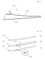
- a metallic butt-strap 10 is used as shown in cross-section in Fig. 1 .
- the butt-strap is attached to the inner mould line (IML) face of the wing skin that-generally faces towards the interior of the wing.
- IML inner mould line
- Prior art butt-strap 10 has as stepped, z-shaped profile, with a short vertical portion 10a joining two horizontal plate portions 10b,c.
- plate 10b fits over a portion of the IML face of cover 20 of the aircraft's wing skin such that the leading edge of cover 20 butts up against vertical portion 10a. This is bolted in place with bolt 30 that is countersunk into cover 20 on its outer-mould-line (OML) face.
- OML outer-mould-line
- Plate 10c is attached to the structure that is to be fixed to the leading edge of the cover.
- a "D"-nose leading edge skin 40 is shown attached to a wing cover leading edge 50 ( Fig. 2 ).
- the "D"-nose skin 40 is usually chosen to be sufficiently thick to overhang the leading edge 50 of cover 20.
- aerodynamic erosion still occurs and the increased thickness also increases drag. Aerodynamic erosion is often exacerbated when composite materials are used.
- Fig. 3 shows schematically how an impact on the leading-edge structure (not shown) attached by butt-strap 10 can lead to catastrophic forces on bolt 30.
- GB-A-1022131 discloses a sectional airfoil that can be assembled using relative swinging movement to effect snap engagements of cooperating latch members.
- spars in an aerofoil section have hook shaped ends that engage with complementary shaped hooks on a trailing and/or leading edge section.
- US 2005/213278 A1 discloses a Faraday cage on the exterior of an aircraft body.
- the conductive grid can be formed from electrically conductive splice plates that join the edges of composite skin panels in the body together.
- the splice plates are tapered to match a corresponding taper of the composite skin panels.
- DE 704327 C discloses an aerofoil section where an edge stiffener is fastened to an edge belt by a fastener.
- the edge stiffener is tapered in the region of the fastening to match a corresponding taper of the edge belt.
- the present invention seeks to ameliorate at least some of the abovementioned problems.
- the invention provides a joint for use in aircraft construction comprising:
- the continuous exterior surface may correspond to a continuous curved or planar surface.
- the continuous exterior surface may be smooth or substantially smooth.
- the thickness of the first portion of the butt-strap at the junction is non-zero but preferably small compared to the thickness of the cover skin.
- the first portion of the butt-strap is located so that a substantially continuous exterior surface is formed at said junction.
- the first portion of the butt-strap may be located so that, adjacent to the junction, the exterior surface of the skin is substantially coplanar with the exterior surface of the first portion of the butt-strap.
- the first portion of the butt-strap may be located so that, adjacent to the junction, the exterior surface of the skin and the exterior surface of the first portion of the butt-strap form a curved substantially continuous exterior surface.
- the joint may include filler or a filler plate located in the recess formed by the distal end or edge of the first portion and the exterior surface of the cover skin adjacent the junction.
- the first portion of the butt-strap tapers towards its distal end, and may give the first portion a wedge-shaped profile.
- the tapering portion may form an angle of about 3° at its distal portion.
- the first portion of the butt-strap may be connected to the skin by a fastener, for example a bolt, including a tapered washer or a tapered collar.
- a fastener for example a bolt, including a tapered washer or a tapered collar.
- the butt-strap may comprise a second portion for connection to an aircraft structure such as a leading-edge or trailing-edge structure.
- the cover skin may be made of a composite material.
- the butt-strap may be metallic.
- the wing may further comprise a filler plate arranged to fill a space between the aircraft structure and the second portion of the butt-strap.
- the plate may be wedge-shaped.
- the distal portion of the skin may be truncated at the upper or lower surface of its distal end.
- the truncated region may be of a shape complementary to the shape of a third portion of the butt-strap, the third portion being between the first portion and the second portion.
- the truncated region may act to retain the skin against the butt-strap.
- the proximal portion and the distal portion of the second surface of the skin may meet to form a step region.
- a distal end of the butt-strap may be retained by the step region.
- a plurality of said butt-straps may be spliced together by connection to an aircraft structure such as a leading- or trailing-edge structure.
- each butt strap may extend continuously under said structure.
- the butt-strap may comprise a portion that extends into a pylon region of the wing.
- the distal portion of the skin may extend over the pylon portion of the butt-strap.
- the invention provides an aerodynamic surface, such as a wing, fin or horizontal stabilizer or the like, incorporating a joint as hereinbefore defined.
- the exterior-facing surface of the distal portion of the skin may have been formed in a first region of the wing's leading or trailing edge by moulding and in a second region of the wing's leading or trailing edge by machining.
- the moulded region of the distal portion may run parallel to spars of the wing.
- the machined region may be located at an undercarriage rib of the wing.
- the skin may comprise conductive foil and there may be electrical continuity between the butt-strap and said foil.
- cut edges of the leading edge of the skin are protected, at least partially by the butt-strap, so that they are not exposed to the air stream in flight.
- the second portion of the butt-strap may have the same form as the first portion of the butt-strap as hereinbefore defined and function in a similar manner as said first portion.
- the invention provides a method of manufacturing a joint for use in aircraft construction comprising forming a cover skin having an interior surface, an exterior surface and a distal portion, said distal portion having an exterior-facing surface, forming a butt-strap having a first portion for connection to the skin, said first portion having an interior surface, an exterior surface and a distal end wherein the method further comprises connecting the first portion of the butt-strap to the distal portion of the skin such that a junction is formed between the exterior surface of the skin and the exterior surface of the first portion of the butt-strap and wherein the exterior-facing surface of the distal portion of the skin is of a shape complementary to the shape of the interior surface of the first portion of the butt-strap and wherein the first portion of the butt-strap tapers towards its distal end such that, at said junction, the exterior surface of the skin and the exterior surface of the first portion of the butt-strap form a substantially continuous exterior surface.
- the skin is of substantially the same thickness in the proximal portion and in the distal portion and the distal portion is offset from the proximal portion at an angle that orients the exterior-facing surface of the distal portion so that it is complementary to the tapering first portion of the butt-strap.
- the exterior-facing surface of the distal portion of the skin may be formed by moulding.
- the moulding may be carried out using a tool, shaped to form the exterior surface of the proximal portion, including an add-on to form the exterior-surface of the distal portion of the skin.
- the moulding may be carried out using a tool shaped to form both the exterior surface of the proximal portion and the exterior-facing surface of the distal portion of the skin.
- the exterior-facing surface of the distal portion of the skin may be formed by machining.
- the exterior-facing surface of the distal portion of the skin may be formed by moulding in a first region of the aircraft component, such as a wing, and by machining in a second region.
- the butt-strap and skin may be bonded together prior to being joined by a fastener.
- a third aspect of the invention provides an aircraft constructed using one or more joints as hereinbefore defined.
- a butt-strap 100 is shown in profile and is seen to be in the form of a mildly stepped, z-shaped profile, with a short vertical portion 100a joining two horizontal plate portions 100b,c.
- plate 100b has a wedge-shaped profile, tapering from its thickest point near the vertical portion 100a to a thin, distal end.
- the thickness of the first portion at the junction formed by the exterior surface of the cover skin at the exterior surface of the butt-strap i.e.; the distal end
- the interior, tapering surface forms an angle of about 3° with the exterior face of plate 100b.
- Butt-strap 100 is bolted in place on the OML of cover 200 with bolt 30, which is countersunk into tapered plate 100b on its exterior face.
- Cover 200 comprises a proximal portion 207, which forms most of the wing skin and a distal, angled portion 205.
- the exterior-facing surface of distal portion 205 recedes at an angle of 3° from the exterior surface of the proximal portion of cover 200.
- the exterior-facing surface of distal portion 205 in this example at its leading edge, is of a shape complementary to the shape of the interior, tapering surface of butt-strap plate 100b.
- the exterior surface of the proximal portion 207 of cover 200 and the exterior surface of plate 100b thus form a substantially continuous surface of the wing. This ideally forms a continuous planar exterior surface.
- the butt-strap 100 may be extruded or machined from aluminium plate, depending on the complexity of the skin contour it needs to match. Internally, where there are no fittings, the fastener collars sit on tapered washers or have collars 35 that accommodate the 3° angle (as shown in Fig. 4 ).
- the butt-strap 100 in this example is used ( Fig. 5 ) to secure a leading edge fitting 70 to cover 200.
- tapered aluminium plates 90 are installed, to level off the angle of the taper 205 of cover 200, provide adjustment to accommodate the various interface tolerances, to act as spreader plates for the fittings 70, and to act as electrical bonding straps.
- Leading edge fitting 70 butts up against spar 80 and the distal end of cover portion 205, which it overlaps by approximately the length of the butt-strap 100. Because of the angled portion 205 of cover 200, there is a wedge-shaped gap between fitting 70 and cover 200. This is filled in with tapered plate 90, through which bolt 30 also passes.
- the butt-straps 100 and internal plates 90 are bonded onto the cover 200 prior to the installation of fastener 30.
- Use of a paste adhesive/shim material such as such as Hysol EA934 allows for the setting of the various dimensions of the construction.
- a combination of fore/aft movement of the taper and the use of liquid shim provides sufficient freedom of adjustment to achieve the correct dimensional fit-up.
- the fit of the LE/TE fittings 70 themselves is dependent on the girth tolerance for spar 80 and the angular relationship between the spar web and the pads on the covers 200. As such tolerance management is demanding and may require shimming/fettling of these components on assembly, as is done on prior-art metal wings.
- the distal end of the angled portion 205 of cover 200 may also be truncated at its lower edge ( Fig. 6 ), forming a more steeply tapered surface 208 that butts up against a corresponding sloped surface 108 on vertical portion 100a of butt-strap 100. The leading edge of the skin portion 205 is thus retained in place against butt-strap 100.
- Heel line 120 is the line at which the plane coincident with the outer mould line of the angled portion 205 of cover 200, if extended sufficiently, would meet the outer surface of the rest of cover 200. Heel line 120 is in line with the leading edge of spar 80. That extended plane is not the true outer surface of cover 200. Rather, the angled portion of cover 200 stops short of the non-angled portion, which is itself extended beyond heel line 120, thus forming step 130, which acts to constrain aft-ward movement of the distal end of portion 100b.
- Leading edge fitting 70 is used to splice sections of butt-strap 100 together ( Fig. 8 ). In an alternative embodiment, (not shown) butt-strap 100 runs continuously under fitting 70.
- cover 200' does not form the ultimate distal end of cover 200', but rather leads into a further distal portion that is parallel to (but displaced from) the rest of the non-angled cover 200'. Cover 200' thus extends over plate 100c of butt-strap 100 at pylon grow-out regions of the wing.
- the (reflex-) angled portion 205 of cover 200 is moulded into the cover in some regions 270 of, for example, the aircraft wing 250 and machined in other regions 260 ( Fig. 10 ).
- the butt-strap 100 runs parallel to the front and rear spars of wing 250 for most of the wing's length (dashed line in Fig. 10 ). At the undercarriage rib it deviates and follows the (shark's fin) contour of the skin in that area 260 (solid line in Fig. 10 ). At the front spar pylon area 275, however, the strap 100 continues parallel to the front spar ( Figs. 9 and 10 ). The strap 100 can either be extended forward as illustrated in Fig. 9 or a separate section can be added forward, effectively to extend the leading edge panel land. In both cases this extra material acts as a spreader plate or reinforcement for the pylon fitting.
- the angle to be moulded at the cover edges requires early definition, especially if the skin tool itself is to be manufactured to this profile. As discussed above, the angle is moulded parallel to the front or rear spars (with the exception of the outboard section 260 of the "sharks fin"). Thus only a small amount of detail definition is required to establish the location of the start (heel line 110) of the 3° angle.
- the heel line 110 is positioned close to the centre of the chord to provide maximum flexibility to fastener and part edge changes later in the design (albeit possibly at a small weight penalty).
- Machining the tool is preferable from a cost cure cycle perspective but has the disadvantage of requiring definition very early on in the manufacturing programme.
- the major drawback of using additional "bolt-on" components is the adverse effect that has on the thermal properties of the tool, which must be accounted for in tool design and component cure cycle.
- a third option is to machine the angle post-cure. That may be the preferred approach where moulding of the feature is difficult or impractical, for example in regions difficult to tape lay or where component wrinkling is expected.
- the cover 200 is likely to be particularly thick (for example, thicker then 20 mm) in such areas and so machining the taper and exposing fibres is likely to be of little structural consequence. Further, it is envisaged that any delamination that does occur will be restrained by bolts 30 at the butt-strap 100, spar 80 and LE/TE fittings 70.
- the external butt-strap arrangement produces, in some embodiments an extra gap/step between strap 100 and cover 200 on the aerodynamic surface ( Fig. 12 ).
- the butt-strap 100 is set onto the skin as part of the skin assembly. As previously described, the strap 100 is bonded/shimmed into place using a suitable adhesive 230 to ensure compliance with the OML 240 as the primary datum. Additionally the taper of the strap 100 can be used to gain adjustment by moving the component fore and aft over the skin. If that results in a foul with the resin edge on the skin, the butt-strap 100 can be fettled to fit. As can be seen in figure 12 the skin moulding process will leave a resin edge 210 that together with the butt-strap 100 will provides a distinct "channel" to retain any aero filler 220 required to complete the transition.
- the external butt-strap approach of the invention provides the benefit of erosion protection of the composite cover 200 by ensuring that there are no cut edges of the cover 200 exposed to the air stream, an important consideration at the leading edge, rather, the cut edge of the cover 200 is inside the wing, shielded by butt-strap 100.
- the internal butt-strap arrangement of the prior art Fig. 2
- the butt-strap arrangement also forms part of the aircraft's lightning protection scheme by providing conducting paths for current resulting from a lightening strike ( Fig. 14 ).
- each conducting path at each butt-strap location on the upper and lower, leading and trailing edges.
- Each conducting path whilst separate from the others, forms a continuous path in which the current can flow, with electrical continuity between the butt-strap sections 100 and to the bronze mesh/foil 280 in the cover 200 itself.
- Continuity between butt-strap sections 100 can be achieved by the arrangement of Fig. 8 .
- Established joining techniques should ensure good electrical bonding
- connection to bronze mesh/foil 280 is achieved in this example via a conducting sleeve 290 around bolt 30 ( Fig. 14(b) ). Attempting to link the butt-strap 100 directly to the mesh/foil 290 is not appropriate due to the potential for corrosion.
- Alternative arrangements include connecting but-strap 100 to mesh/foil 280 via bolts 30, either at the bolt's head ( Fig. 14(a) or at a region along its length ( Fig. 14(c) ).
Landscapes
- Engineering & Computer Science (AREA)
- Mechanical Engineering (AREA)
- Aviation & Aerospace Engineering (AREA)
- Connection Of Plates (AREA)
- Joining Of Building Structures In Genera (AREA)
- Pressure Welding/Diffusion-Bonding (AREA)
- Adhesives Or Adhesive Processes (AREA)
- Road Paving Structures (AREA)
Applications Claiming Priority (2)
| Application Number | Priority Date | Filing Date | Title |
|---|---|---|---|
| GBGB0525896.7A GB0525896D0 (en) | 2005-12-20 | 2005-12-20 | A joint for use in aircraft construction |
| PCT/GB2006/004439 WO2007071905A1 (en) | 2005-12-20 | 2006-11-28 | A joint for use in aircraft construction |
Publications (2)
| Publication Number | Publication Date |
|---|---|
| EP1963178A1 EP1963178A1 (en) | 2008-09-03 |
| EP1963178B1 true EP1963178B1 (en) | 2010-08-04 |
Family
ID=35840772
Family Applications (1)
| Application Number | Title | Priority Date | Filing Date |
|---|---|---|---|
| EP06808699A Ceased EP1963178B1 (en) | 2005-12-20 | 2006-11-28 | A joint for use in aircraft construction |
Country Status (11)
| Country | Link |
|---|---|
| US (2) | USRE47738E1 (enExample) |
| EP (1) | EP1963178B1 (enExample) |
| JP (1) | JP2009519861A (enExample) |
| CN (1) | CN101341070A (enExample) |
| AT (1) | ATE476359T1 (enExample) |
| BR (1) | BRPI0620070A2 (enExample) |
| CA (1) | CA2633106C (enExample) |
| DE (1) | DE602006016006D1 (enExample) |
| GB (1) | GB0525896D0 (enExample) |
| RU (1) | RU2427500C2 (enExample) |
| WO (1) | WO2007071905A1 (enExample) |
Cited By (1)
| Publication number | Priority date | Publication date | Assignee | Title |
|---|---|---|---|---|
| DE102016210325A1 (de) * | 2016-06-10 | 2017-12-14 | Airbus Operations Gmbh | Bauteilanordnung zur Ausbildung einer Tragstruktur eines Luft- oder Raumfahrzeugs |
Families Citing this family (64)
| Publication number | Priority date | Publication date | Assignee | Title |
|---|---|---|---|---|
| GB0609166D0 (en) * | 2006-05-09 | 2006-06-21 | Airbus Uk Ltd | Apparatus for and method of inhibiting delamination |
| JP4657194B2 (ja) * | 2006-11-20 | 2011-03-23 | 本田技研工業株式会社 | 前縁スキンの段差調整構造および前縁スキンの組付方法 |
| FR2916424B1 (fr) * | 2007-05-23 | 2009-08-21 | Airbus France Sa | Mat d'accrochage de moteur pour aeronef comprenant une cale biaise pour la fixation de l'attache moteur avant |
| RU2476348C2 (ru) * | 2007-05-31 | 2013-02-27 | Эйрбас Оператионс Гмбх | Способ производства составной обшивки в области авиационной и космической промышленности |
| US8398027B2 (en) * | 2007-09-17 | 2013-03-19 | The Boeing Company | Method and apparatus for reinforcing composite structures |
| US8490920B2 (en) * | 2007-10-12 | 2013-07-23 | Abe Karem | Composite bulkhead and skin construction |
| DE102008013365B4 (de) * | 2008-03-10 | 2011-03-17 | Airbus Operations Gmbh | Querstoßverbindung zwischen zwei Rumpfsektionen |
| GB0805268D0 (en) * | 2008-03-25 | 2008-04-30 | Airbus Uk Ltd | Composite joint protection |
| GB0805963D0 (en) * | 2008-04-02 | 2008-05-07 | Airbus Uk Ltd | Aircraft structure |
| IT1390909B1 (it) * | 2008-07-16 | 2011-10-19 | Alenia Aeronautica Spa | Elemento strutturale a rigidezza calcolata, con caratteristiche di assorbimento di spostamenti e copertura interstizi |
| FR2936495B1 (fr) * | 2008-09-30 | 2011-06-03 | Airbus France | Assemblage de panneaux pour fuselage d'aeronef. |
| GB0901640D0 (en) * | 2009-02-03 | 2009-03-11 | Airbus Uk Ltd | Joint |
| ES2384920B1 (es) * | 2009-03-31 | 2013-05-21 | Airbus Operations, S.L. | Pieza de material con una rampa entre dos zonas. |
| GB0905818D0 (en) * | 2009-04-06 | 2009-05-20 | Airbus Uk Ltd | Coupling assembly |
| US8282042B2 (en) * | 2009-06-22 | 2012-10-09 | The Boeing Company | Skin panel joint for improved airflow |
| GB0910938D0 (en) * | 2009-06-25 | 2009-08-05 | Airbus Operations Ltd | Method of manufacturing a structure |
| EP2316629B1 (en) * | 2009-10-27 | 2012-05-23 | Lm Glasfiber A/S | Modular mould system for manufacturing a shell part |
| DE102009060693A1 (de) * | 2009-12-29 | 2011-06-30 | Airbus Operations GmbH, 21129 | Versteifungselement für ein Luftfahrzeug und Flächengebilde mit einem derartigen Versteifungselement |
| ES2396327B1 (es) * | 2010-06-10 | 2014-02-06 | Airbus Operations, S.L. | Procedimiento para la fabricación de piezas grandes de material compuesto controlando el espesor de sus bordes |
| DE102010026839A1 (de) | 2010-07-12 | 2012-01-12 | Airbus Operations Gmbh | Aerodynamische Verkleidungsvorrichtung, Flugzeug-Bauteilanordnung mit einer aerodynamischen Verkleidungsvorrichtung sowie Verfahren zur Montage eines solchen Verkleidungsteils |
| US8333345B2 (en) * | 2010-08-26 | 2012-12-18 | The Boeing Company | Composite aircraft joint |
| GB201016279D0 (en) | 2010-09-28 | 2010-11-10 | Airbus Operations Ltd | Stiffener run-out |
| ES2396881B1 (es) * | 2010-11-30 | 2014-01-29 | Airbus Operations, S.L. | Disposición de interfaz entre dos componentes de una estructura de una aeronave usando una pieza de sellado. |
| ES2396882B1 (es) * | 2010-11-30 | 2014-01-29 | Airbus Operations, S.L. | Disposición de interfaz entre dos componentes de una estructura de una aeronave. |
| ES2403361B1 (es) * | 2010-12-17 | 2014-04-29 | Airbus Operations, S.L. | Optimización de estructuras sometidas a corrientes de gases calientes. |
| FR2970463B1 (fr) * | 2011-01-17 | 2013-02-15 | Airbus Operations Sas | Dispositif d'eclissage a tenue mecanique amelioree. |
| RU2475425C1 (ru) * | 2011-10-06 | 2013-02-20 | Федеральное государственное унитарное предприятие "Государственный космический научно-производственный центр имени М.В. Хруничева" | Устройство металлизации корпуса изделия |
| US20130114994A1 (en) | 2011-11-04 | 2013-05-09 | Robert Erik Grip | Truss end pad fitting |
| US9574587B2 (en) | 2011-11-04 | 2017-02-21 | The Boeing Company | Preloading a fastener of a mechanical fitting |
| GB201200912D0 (en) * | 2012-01-19 | 2012-02-29 | Airbus Operations Ltd | Fastener receptacle strip |
| GB201205079D0 (en) * | 2012-03-22 | 2012-05-09 | Airbus Operations Ltd | Seal assembly for an aircraft wing |
| US9180956B1 (en) * | 2012-04-11 | 2015-11-10 | The Boeing Company | Methods and apparatus for attaching an aircraft wing assembly to an aircraft body |
| ES2426111B1 (es) * | 2012-04-17 | 2015-03-24 | Airbus Operations S.L. | Interfaz para superficie de sustentación de aeronave |
| EP2653376B1 (en) * | 2012-04-18 | 2016-03-23 | Airbus Operations, S.L. | Bolted joint of the cover of an access opening in an aircraft lifting surface |
| GB201209437D0 (en) * | 2012-05-28 | 2012-07-11 | Kitchener Renato | Power supply and battery charger |
| US8985514B2 (en) * | 2012-06-20 | 2015-03-24 | The Boeing Company | Composite structural panels and aircraft fuselages |
| US8857765B2 (en) * | 2012-10-16 | 2014-10-14 | The Boeing Company | Method and apparatus for attaching an aircraft fuselage frame to a wing box |
| EP2909486B1 (en) * | 2012-10-22 | 2018-12-12 | BAE SYSTEMS plc | Hybrid joint manufacutring |
| US9415853B2 (en) * | 2013-01-30 | 2016-08-16 | The Boeing Company | Surface sealing system |
| FR3015433B1 (fr) | 2013-12-23 | 2016-02-12 | Airbus Operations Sas | Ensemble pour aeronef comprenant un mat d'accrochage integre a la nacelle et agence en partie arriere du fuselage |
| US9399507B2 (en) | 2014-01-22 | 2016-07-26 | The Boeing Company | Joints between a composite skin and a load-bearing component and methods of forming same |
| US9676469B2 (en) | 2014-04-10 | 2017-06-13 | Lockheed Martin Corporation | System and method for fastening structures |
| US10603888B2 (en) * | 2014-04-10 | 2020-03-31 | The Boeing Company | Filling and leveling methods and apparatus for building tight tolerance surfaces |
| US9896190B1 (en) * | 2014-05-07 | 2018-02-20 | The Boeing Company | Wing leading edge architecture suitable for laminar flow |
| EP3142923B1 (en) * | 2014-05-15 | 2020-05-06 | Sikorsky Aircraft Corporation | Metallic dimpled doubler |
| US10329009B2 (en) * | 2014-09-17 | 2019-06-25 | The Boeing Company | Composite wing edge attachment and method |
| US9925625B2 (en) * | 2015-05-04 | 2018-03-27 | The Boeing Company | Assembly of an aircraft structure assembly without shimming, locating fixtures or final-hole-size drill jigs |
| CN106697327B (zh) * | 2016-12-19 | 2019-10-18 | 中航成飞民用飞机有限责任公司 | 飞机壁板对接结构 |
| US10773789B2 (en) * | 2017-07-07 | 2020-09-15 | The Boeing Company | Skin-panel interface of an aircraft |
| CN109677586A (zh) * | 2019-01-18 | 2019-04-26 | 中国商用飞机有限责任公司北京民用飞机技术研究中心 | 一种腹板、飞机机翼和飞机 |
| US11884055B2 (en) * | 2019-03-26 | 2024-01-30 | The Boeing Company | Laminated hybrid metallized polymer films, system, and method for erosion protection of composite structures |
| US11383820B2 (en) * | 2019-06-11 | 2022-07-12 | The Boeing Company | Aerodynamic surface lap splice |
| CN110466734B (zh) * | 2019-08-26 | 2022-08-19 | 中国航空工业集团公司沈阳飞机设计研究所 | 一种锯齿缝对接蒙皮的带板 |
| US11524762B2 (en) * | 2020-02-21 | 2022-12-13 | The Boeing Company | Fuselage structure splice |
| US11572152B2 (en) | 2020-05-21 | 2023-02-07 | The Boeing Company | Structural composite airfoils with a single spar, and related methods |
| US11401026B2 (en) | 2020-05-21 | 2022-08-02 | The Boeing Company | Structural composite airfoils with a single spar, and related methods |
| US11554848B2 (en) | 2020-05-21 | 2023-01-17 | The Boeing Company | Structural composite airfoils with a single spar, and related methods |
| US11453476B2 (en) * | 2020-05-21 | 2022-09-27 | The Boeing Company | Structural composite airfoils with an improved leading edge, and related methods |
| CN114771802A (zh) | 2021-01-22 | 2022-07-22 | 波音公司 | 空气动力学结构以及形成空气动力学结构的方法 |
| EP4053014B1 (en) * | 2021-03-05 | 2024-12-18 | The Boeing Company | Assembly and method connecting an aircraft wing aft spar root to an aircraft body fuselage |
| CN113376044B (zh) * | 2021-06-10 | 2022-07-12 | 中国兵器工业第五九研究所 | 一种高温高压气体冲刷实验装置 |
| CN114684346A (zh) * | 2021-12-31 | 2022-07-01 | 中国航空工业集团公司西安飞机设计研究所 | 一种长桁接头 |
| EP4303120A1 (en) * | 2022-07-07 | 2024-01-10 | Airbus Operations S.L.U. | Composite multi-spar aircraft lifting surface |
| CN119489923A (zh) * | 2024-12-25 | 2025-02-21 | 中国航空工业集团公司西安飞机设计研究所 | 一种加筋壁板对接结构及设计方法 |
Family Cites Families (20)
| Publication number | Priority date | Publication date | Assignee | Title |
|---|---|---|---|---|
| DE704327C (de) * | 1939-02-09 | 1941-03-28 | Henschel Flugzeug Werke A G | Flugzeugfluegel |
| GB1022131A (en) * | 1963-06-10 | 1966-03-09 | Monte Copter Inc | Sectional airfoil |
| IL63240A (en) | 1980-07-11 | 1984-12-31 | Weecan Marine | Method and apparatus for manufacturing an integral shell formed body |
| US4507011A (en) * | 1982-05-03 | 1985-03-26 | The Boeing Company | Reinforced elastomer attachment joint |
| SU1420823A1 (ru) * | 1987-01-30 | 1996-09-20 | Е.А. Бычковский | Хвостовая часть крыла самолета |
| JPS63240494A (ja) * | 1987-03-26 | 1988-10-06 | 川崎重工業株式会社 | 航空機用翼の前縁保護構造 |
| US4888451A (en) | 1988-11-29 | 1989-12-19 | United Technologies Corporation | Electrical continuity means for composite joints |
| US5803406A (en) * | 1996-04-22 | 1998-09-08 | The United States Of America As Represented By The Administrator Of The National Aeronautics And Space Administration | Integrated thermal insulation system for spacecraft |
| US6375120B1 (en) * | 1997-07-14 | 2002-04-23 | Jason M. Wolnek | Method and apparatus for building a metal/composite hybrid airplane component |
| RU12819U1 (ru) * | 1999-04-28 | 2000-02-10 | Егер Владимир Сергеевич | Композитное кессонное крыло легкого самолета |
| WO2002014147A1 (en) * | 2000-08-11 | 2002-02-21 | Dunlop Aerospace Limited | Wheel hub assemblies |
| DE10238820A1 (de) * | 2002-08-23 | 2004-03-11 | Airbus Deutschland Gmbh | Anordung zur Erfindung von dünnwandigen Metallstrukturen |
| GB0329373D0 (en) * | 2003-12-18 | 2004-01-21 | Airbus Uk Ltd | Method of joining structural elements in an aircraft |
| US7554785B2 (en) * | 2004-03-23 | 2009-06-30 | The Boeing Company | Lightning damage protection for composite aircraft |
| US20060251496A1 (en) * | 2004-07-09 | 2006-11-09 | Bae Systems Plc | Fastener arrangement for fastening a detachable panel |
| US7296656B2 (en) * | 2005-04-22 | 2007-11-20 | United Technologies Corporation | Acoustic mechanical retainer |
| FR2905739B1 (fr) * | 2006-09-08 | 2008-11-07 | Airbus France Sas | Assemblage de panneaux et procede de montage d'un assemblage de panneaux |
| JP4657194B2 (ja) * | 2006-11-20 | 2011-03-23 | 本田技研工業株式会社 | 前縁スキンの段差調整構造および前縁スキンの組付方法 |
| US8016230B2 (en) * | 2007-05-11 | 2011-09-13 | The Boeing Company | Fastner-free primary structural joint for sandwich panels |
| US8398027B2 (en) * | 2007-09-17 | 2013-03-19 | The Boeing Company | Method and apparatus for reinforcing composite structures |
-
2005
- 2005-12-20 GB GBGB0525896.7A patent/GB0525896D0/en not_active Ceased
-
2006
- 2006-11-28 EP EP06808699A patent/EP1963178B1/en not_active Ceased
- 2006-11-28 WO PCT/GB2006/004439 patent/WO2007071905A1/en not_active Ceased
- 2006-11-28 CN CNA2006800478322A patent/CN101341070A/zh active Pending
- 2006-11-28 US US13/886,454 patent/USRE47738E1/en not_active Expired - Fee Related
- 2006-11-28 BR BRPI0620070-2A patent/BRPI0620070A2/pt not_active IP Right Cessation
- 2006-11-28 JP JP2008546567A patent/JP2009519861A/ja active Pending
- 2006-11-28 US US12/097,328 patent/US7909290B2/en not_active Ceased
- 2006-11-28 RU RU2008129606/11A patent/RU2427500C2/ru not_active IP Right Cessation
- 2006-11-28 AT AT06808699T patent/ATE476359T1/de not_active IP Right Cessation
- 2006-11-28 DE DE602006016006T patent/DE602006016006D1/de active Active
- 2006-11-28 CA CA2633106A patent/CA2633106C/en not_active Expired - Fee Related
Cited By (2)
| Publication number | Priority date | Publication date | Assignee | Title |
|---|---|---|---|---|
| DE102016210325A1 (de) * | 2016-06-10 | 2017-12-14 | Airbus Operations Gmbh | Bauteilanordnung zur Ausbildung einer Tragstruktur eines Luft- oder Raumfahrzeugs |
| DE102016210325B4 (de) | 2016-06-10 | 2021-07-15 | Airbus Operations Gmbh | Bauteilanordnung zur Ausbildung einer Tragstruktur eines Luft- oder Raumfahrzeugs |
Also Published As
| Publication number | Publication date |
|---|---|
| ATE476359T1 (de) | 2010-08-15 |
| GB0525896D0 (en) | 2006-02-01 |
| JP2009519861A (ja) | 2009-05-21 |
| EP1963178A1 (en) | 2008-09-03 |
| RU2427500C2 (ru) | 2011-08-27 |
| US20080258008A1 (en) | 2008-10-23 |
| CN101341070A (zh) | 2009-01-07 |
| DE602006016006D1 (de) | 2010-09-16 |
| CA2633106C (en) | 2013-08-06 |
| BRPI0620070A2 (pt) | 2011-11-01 |
| USRE47738E1 (en) | 2019-11-26 |
| RU2008129606A (ru) | 2010-01-27 |
| US7909290B2 (en) | 2011-03-22 |
| CA2633106A1 (en) | 2007-06-28 |
| WO2007071905A1 (en) | 2007-06-28 |
Similar Documents
| Publication | Publication Date | Title |
|---|---|---|
| EP1963178B1 (en) | A joint for use in aircraft construction | |
| US8186622B2 (en) | Aircraft component | |
| CA2911447C (en) | Stiffened composite panels and method of their manufacture | |
| KR102312286B1 (ko) | 일체형 흡입구 립 스킨 디자인 | |
| EP3000719B1 (en) | Composite wing edge attachment and method | |
| US9085350B2 (en) | Aircraft wing cover comprising a sandwich panel and methods to manufacture and design the said wing cover | |
| EP2824030B1 (en) | Apparatus and methods for joining composite structures of aircrafts | |
| EP3650333B1 (en) | Composite spar for aircraft wing | |
| US9862477B2 (en) | Aircraft structure | |
| US20110233338A1 (en) | Joint | |
| US11772775B2 (en) | Shear ties for aircraft wing | |
| US11608157B2 (en) | Slat for an aircraft wing and method for making the same | |
| US10953624B2 (en) | Aircraft airfoil having a stitched trailing edge and manufacturing method thereof | |
| CA2829899A1 (en) | Joint for composite wings | |
| EP2977313A1 (en) | Rib foot | |
| US20120132752A1 (en) | Interface arrangement between two components of an aircraft structure using a sealing part | |
| US12351304B2 (en) | Wing-box structure | |
| EP4491505A1 (en) | Composite aircraft door and method for manufacturing the same |
Legal Events
| Date | Code | Title | Description |
|---|---|---|---|
| PUAI | Public reference made under article 153(3) epc to a published international application that has entered the european phase |
Free format text: ORIGINAL CODE: 0009012 |
|
| 17P | Request for examination filed |
Effective date: 20080610 |
|
| AK | Designated contracting states |
Kind code of ref document: A1 Designated state(s): AT BE BG CH CY CZ DE DK EE ES FI FR GB GR HU IE IS IT LI LT LU LV MC NL PL PT RO SE SI SK TR |
|
| 17Q | First examination report despatched |
Effective date: 20090506 |
|
| GRAP | Despatch of communication of intention to grant a patent |
Free format text: ORIGINAL CODE: EPIDOSNIGR1 |
|
| GRAS | Grant fee paid |
Free format text: ORIGINAL CODE: EPIDOSNIGR3 |
|
| RAP1 | Party data changed (applicant data changed or rights of an application transferred) |
Owner name: AIRBUS OPERATIONS LIMITED |
|
| GRAA | (expected) grant |
Free format text: ORIGINAL CODE: 0009210 |
|
| AK | Designated contracting states |
Kind code of ref document: B1 Designated state(s): AT BE BG CH CY CZ DE DK EE ES FI FR GB GR HU IE IS IT LI LT LU LV MC NL PL PT RO SE SI SK TR |
|
| REG | Reference to a national code |
Ref country code: GB Ref legal event code: FG4D |
|
| REG | Reference to a national code |
Ref country code: CH Ref legal event code: EP |
|
| REG | Reference to a national code |
Ref country code: IE Ref legal event code: FG4D |
|
| REF | Corresponds to: |
Ref document number: 602006016006 Country of ref document: DE Date of ref document: 20100916 Kind code of ref document: P |
|
| REG | Reference to a national code |
Ref country code: NL Ref legal event code: VDEP Effective date: 20100804 |
|
| LTIE | Lt: invalidation of european patent or patent extension |
Effective date: 20100804 |
|
| PG25 | Lapsed in a contracting state [announced via postgrant information from national office to epo] |
Ref country code: LT Free format text: LAPSE BECAUSE OF FAILURE TO SUBMIT A TRANSLATION OF THE DESCRIPTION OR TO PAY THE FEE WITHIN THE PRESCRIBED TIME-LIMIT Effective date: 20100804 Ref country code: NL Free format text: LAPSE BECAUSE OF FAILURE TO SUBMIT A TRANSLATION OF THE DESCRIPTION OR TO PAY THE FEE WITHIN THE PRESCRIBED TIME-LIMIT Effective date: 20100804 Ref country code: FI Free format text: LAPSE BECAUSE OF FAILURE TO SUBMIT A TRANSLATION OF THE DESCRIPTION OR TO PAY THE FEE WITHIN THE PRESCRIBED TIME-LIMIT Effective date: 20100804 Ref country code: AT Free format text: LAPSE BECAUSE OF FAILURE TO SUBMIT A TRANSLATION OF THE DESCRIPTION OR TO PAY THE FEE WITHIN THE PRESCRIBED TIME-LIMIT Effective date: 20100804 |
|
| PG25 | Lapsed in a contracting state [announced via postgrant information from national office to epo] |
Ref country code: BG Free format text: LAPSE BECAUSE OF FAILURE TO SUBMIT A TRANSLATION OF THE DESCRIPTION OR TO PAY THE FEE WITHIN THE PRESCRIBED TIME-LIMIT Effective date: 20101104 Ref country code: CY Free format text: LAPSE BECAUSE OF FAILURE TO SUBMIT A TRANSLATION OF THE DESCRIPTION OR TO PAY THE FEE WITHIN THE PRESCRIBED TIME-LIMIT Effective date: 20100804 Ref country code: PL Free format text: LAPSE BECAUSE OF FAILURE TO SUBMIT A TRANSLATION OF THE DESCRIPTION OR TO PAY THE FEE WITHIN THE PRESCRIBED TIME-LIMIT Effective date: 20100804 Ref country code: PT Free format text: LAPSE BECAUSE OF FAILURE TO SUBMIT A TRANSLATION OF THE DESCRIPTION OR TO PAY THE FEE WITHIN THE PRESCRIBED TIME-LIMIT Effective date: 20101206 Ref country code: SI Free format text: LAPSE BECAUSE OF FAILURE TO SUBMIT A TRANSLATION OF THE DESCRIPTION OR TO PAY THE FEE WITHIN THE PRESCRIBED TIME-LIMIT Effective date: 20100804 Ref country code: IS Free format text: LAPSE BECAUSE OF FAILURE TO SUBMIT A TRANSLATION OF THE DESCRIPTION OR TO PAY THE FEE WITHIN THE PRESCRIBED TIME-LIMIT Effective date: 20101204 |
|
| PG25 | Lapsed in a contracting state [announced via postgrant information from national office to epo] |
Ref country code: SE Free format text: LAPSE BECAUSE OF FAILURE TO SUBMIT A TRANSLATION OF THE DESCRIPTION OR TO PAY THE FEE WITHIN THE PRESCRIBED TIME-LIMIT Effective date: 20100804 Ref country code: BE Free format text: LAPSE BECAUSE OF FAILURE TO SUBMIT A TRANSLATION OF THE DESCRIPTION OR TO PAY THE FEE WITHIN THE PRESCRIBED TIME-LIMIT Effective date: 20100804 Ref country code: GR Free format text: LAPSE BECAUSE OF FAILURE TO SUBMIT A TRANSLATION OF THE DESCRIPTION OR TO PAY THE FEE WITHIN THE PRESCRIBED TIME-LIMIT Effective date: 20101105 Ref country code: LV Free format text: LAPSE BECAUSE OF FAILURE TO SUBMIT A TRANSLATION OF THE DESCRIPTION OR TO PAY THE FEE WITHIN THE PRESCRIBED TIME-LIMIT Effective date: 20100804 |
|
| PG25 | Lapsed in a contracting state [announced via postgrant information from national office to epo] |
Ref country code: DK Free format text: LAPSE BECAUSE OF FAILURE TO SUBMIT A TRANSLATION OF THE DESCRIPTION OR TO PAY THE FEE WITHIN THE PRESCRIBED TIME-LIMIT Effective date: 20100804 |
|
| PG25 | Lapsed in a contracting state [announced via postgrant information from national office to epo] |
Ref country code: SK Free format text: LAPSE BECAUSE OF FAILURE TO SUBMIT A TRANSLATION OF THE DESCRIPTION OR TO PAY THE FEE WITHIN THE PRESCRIBED TIME-LIMIT Effective date: 20100804 Ref country code: CZ Free format text: LAPSE BECAUSE OF FAILURE TO SUBMIT A TRANSLATION OF THE DESCRIPTION OR TO PAY THE FEE WITHIN THE PRESCRIBED TIME-LIMIT Effective date: 20100804 Ref country code: RO Free format text: LAPSE BECAUSE OF FAILURE TO SUBMIT A TRANSLATION OF THE DESCRIPTION OR TO PAY THE FEE WITHIN THE PRESCRIBED TIME-LIMIT Effective date: 20100804 Ref country code: EE Free format text: LAPSE BECAUSE OF FAILURE TO SUBMIT A TRANSLATION OF THE DESCRIPTION OR TO PAY THE FEE WITHIN THE PRESCRIBED TIME-LIMIT Effective date: 20100804 |
|
| PLBE | No opposition filed within time limit |
Free format text: ORIGINAL CODE: 0009261 |
|
| STAA | Information on the status of an ep patent application or granted ep patent |
Free format text: STATUS: NO OPPOSITION FILED WITHIN TIME LIMIT |
|
| PG25 | Lapsed in a contracting state [announced via postgrant information from national office to epo] |
Ref country code: ES Free format text: LAPSE BECAUSE OF FAILURE TO SUBMIT A TRANSLATION OF THE DESCRIPTION OR TO PAY THE FEE WITHIN THE PRESCRIBED TIME-LIMIT Effective date: 20101115 Ref country code: MC Free format text: LAPSE BECAUSE OF NON-PAYMENT OF DUE FEES Effective date: 20101130 |
|
| REG | Reference to a national code |
Ref country code: CH Ref legal event code: PL |
|
| 26N | No opposition filed |
Effective date: 20110506 |
|
| PG25 | Lapsed in a contracting state [announced via postgrant information from national office to epo] |
Ref country code: LI Free format text: LAPSE BECAUSE OF NON-PAYMENT OF DUE FEES Effective date: 20101130 Ref country code: CH Free format text: LAPSE BECAUSE OF NON-PAYMENT OF DUE FEES Effective date: 20101130 |
|
| REG | Reference to a national code |
Ref country code: DE Ref legal event code: R097 Ref document number: 602006016006 Country of ref document: DE Effective date: 20110506 |
|
| PG25 | Lapsed in a contracting state [announced via postgrant information from national office to epo] |
Ref country code: IE Free format text: LAPSE BECAUSE OF NON-PAYMENT OF DUE FEES Effective date: 20101128 |
|
| PG25 | Lapsed in a contracting state [announced via postgrant information from national office to epo] |
Ref country code: LU Free format text: LAPSE BECAUSE OF NON-PAYMENT OF DUE FEES Effective date: 20101128 Ref country code: HU Free format text: LAPSE BECAUSE OF FAILURE TO SUBMIT A TRANSLATION OF THE DESCRIPTION OR TO PAY THE FEE WITHIN THE PRESCRIBED TIME-LIMIT Effective date: 20110205 |
|
| PG25 | Lapsed in a contracting state [announced via postgrant information from national office to epo] |
Ref country code: TR Free format text: LAPSE BECAUSE OF FAILURE TO SUBMIT A TRANSLATION OF THE DESCRIPTION OR TO PAY THE FEE WITHIN THE PRESCRIBED TIME-LIMIT Effective date: 20100804 |
|
| REG | Reference to a national code |
Ref country code: FR Ref legal event code: PLFP Year of fee payment: 10 |
|
| PGFP | Annual fee paid to national office [announced via postgrant information from national office to epo] |
Ref country code: IT Payment date: 20151124 Year of fee payment: 10 |
|
| REG | Reference to a national code |
Ref country code: FR Ref legal event code: PLFP Year of fee payment: 11 |
|
| PG25 | Lapsed in a contracting state [announced via postgrant information from national office to epo] |
Ref country code: IT Free format text: LAPSE BECAUSE OF NON-PAYMENT OF DUE FEES Effective date: 20161128 |
|
| REG | Reference to a national code |
Ref country code: FR Ref legal event code: PLFP Year of fee payment: 12 |
|
| PGFP | Annual fee paid to national office [announced via postgrant information from national office to epo] |
Ref country code: DE Payment date: 20201119 Year of fee payment: 15 Ref country code: FR Payment date: 20201120 Year of fee payment: 15 Ref country code: GB Payment date: 20201120 Year of fee payment: 15 |
|
| REG | Reference to a national code |
Ref country code: DE Ref legal event code: R119 Ref document number: 602006016006 Country of ref document: DE |
|
| GBPC | Gb: european patent ceased through non-payment of renewal fee |
Effective date: 20211128 |
|
| PG25 | Lapsed in a contracting state [announced via postgrant information from national office to epo] |
Ref country code: GB Free format text: LAPSE BECAUSE OF NON-PAYMENT OF DUE FEES Effective date: 20211128 Ref country code: DE Free format text: LAPSE BECAUSE OF NON-PAYMENT OF DUE FEES Effective date: 20220601 |
|
| PG25 | Lapsed in a contracting state [announced via postgrant information from national office to epo] |
Ref country code: FR Free format text: LAPSE BECAUSE OF NON-PAYMENT OF DUE FEES Effective date: 20211130 |