US9896190B1 - Wing leading edge architecture suitable for laminar flow - Google Patents
Wing leading edge architecture suitable for laminar flow Download PDFInfo
- Publication number
- US9896190B1 US9896190B1 US14/271,477 US201414271477A US9896190B1 US 9896190 B1 US9896190 B1 US 9896190B1 US 201414271477 A US201414271477 A US 201414271477A US 9896190 B1 US9896190 B1 US 9896190B1
- Authority
- US
- United States
- Prior art keywords
- leading edge
- skin panel
- edge skin
- wing
- fixed leading
- Prior art date
- Legal status (The legal status is an assumption and is not a legal conclusion. Google has not performed a legal analysis and makes no representation as to the accuracy of the status listed.)
- Active, expires
Links
- 239000003351 stiffener Substances 0.000 claims description 14
- 230000007246 mechanism Effects 0.000 claims description 11
- 238000004891 communication Methods 0.000 claims description 8
- 239000012530 fluid Substances 0.000 claims description 8
- 229910052751 metal Inorganic materials 0.000 claims description 6
- 239000002184 metal Substances 0.000 claims description 6
- 230000013011 mating Effects 0.000 claims description 4
- 230000004044 response Effects 0.000 claims description 4
- 239000000463 material Substances 0.000 claims description 3
- 230000008878 coupling Effects 0.000 claims description 2
- 238000010168 coupling process Methods 0.000 claims description 2
- 238000005859 coupling reaction Methods 0.000 claims description 2
- 238000013022 venting Methods 0.000 claims description 2
- 238000010586 diagram Methods 0.000 description 14
- 238000013461 design Methods 0.000 description 8
- 238000003466 welding Methods 0.000 description 5
- 238000013459 approach Methods 0.000 description 4
- 230000006870 function Effects 0.000 description 4
- 238000000034 method Methods 0.000 description 4
- 229910052782 aluminium Inorganic materials 0.000 description 3
- XAGFODPZIPBFFR-UHFFFAOYSA-N aluminium Chemical compound [Al] XAGFODPZIPBFFR-UHFFFAOYSA-N 0.000 description 3
- 230000000712 assembly Effects 0.000 description 3
- 238000000429 assembly Methods 0.000 description 3
- 239000004593 Epoxy Substances 0.000 description 2
- RTAQQCXQSZGOHL-UHFFFAOYSA-N Titanium Chemical compound [Ti] RTAQQCXQSZGOHL-UHFFFAOYSA-N 0.000 description 2
- 238000012986 modification Methods 0.000 description 2
- 230000004048 modification Effects 0.000 description 2
- 239000010936 titanium Substances 0.000 description 2
- 229910052719 titanium Inorganic materials 0.000 description 2
- 230000007704 transition Effects 0.000 description 2
- OKTJSMMVPCPJKN-UHFFFAOYSA-N Carbon Chemical compound [C] OKTJSMMVPCPJKN-UHFFFAOYSA-N 0.000 description 1
- 230000002411 adverse Effects 0.000 description 1
- 230000008901 benefit Effects 0.000 description 1
- 238000005219 brazing Methods 0.000 description 1
- 229910052799 carbon Inorganic materials 0.000 description 1
- 239000002131 composite material Substances 0.000 description 1
- 230000003111 delayed effect Effects 0.000 description 1
- 230000000694 effects Effects 0.000 description 1
- 239000000945 filler Substances 0.000 description 1
- 239000000446 fuel Substances 0.000 description 1
- 238000010348 incorporation Methods 0.000 description 1
- 238000009434 installation Methods 0.000 description 1
- 230000003993 interaction Effects 0.000 description 1
- 238000004519 manufacturing process Methods 0.000 description 1
- 238000003801 milling Methods 0.000 description 1
- 230000002265 prevention Effects 0.000 description 1
- 230000008569 process Effects 0.000 description 1
- 230000009467 reduction Effects 0.000 description 1
- 238000005476 soldering Methods 0.000 description 1
- 238000003756 stirring Methods 0.000 description 1
- 239000000126 substance Substances 0.000 description 1
- 238000012360 testing method Methods 0.000 description 1
- 238000012546 transfer Methods 0.000 description 1
Images


Classifications
-
- B—PERFORMING OPERATIONS; TRANSPORTING
- B64—AIRCRAFT; AVIATION; COSMONAUTICS
- B64C—AEROPLANES; HELICOPTERS
- B64C21/00—Influencing air flow over aircraft surfaces by affecting boundary layer flow
- B64C21/02—Influencing air flow over aircraft surfaces by affecting boundary layer flow by use of slot, ducts, porous areas or the like
- B64C21/04—Influencing air flow over aircraft surfaces by affecting boundary layer flow by use of slot, ducts, porous areas or the like for blowing
-
- B—PERFORMING OPERATIONS; TRANSPORTING
- B64—AIRCRAFT; AVIATION; COSMONAUTICS
- B64C—AEROPLANES; HELICOPTERS
- B64C3/00—Wings
- B64C3/10—Shape of wings
- B64C3/14—Aerofoil profile
-
- B—PERFORMING OPERATIONS; TRANSPORTING
- B64—AIRCRAFT; AVIATION; COSMONAUTICS
- B64C—AEROPLANES; HELICOPTERS
- B64C9/00—Adjustable control surfaces or members, e.g. rudders
- B64C9/14—Adjustable control surfaces or members, e.g. rudders forming slots
- B64C9/22—Adjustable control surfaces or members, e.g. rudders forming slots at the front of the wing
- B64C9/24—Adjustable control surfaces or members, e.g. rudders forming slots at the front of the wing by single flap
-
- B—PERFORMING OPERATIONS; TRANSPORTING
- B64—AIRCRAFT; AVIATION; COSMONAUTICS
- B64C—AEROPLANES; HELICOPTERS
- B64C9/00—Adjustable control surfaces or members, e.g. rudders
- B64C9/34—Adjustable control surfaces or members, e.g. rudders collapsing or retracting against or within other surfaces or other members
-
- B—PERFORMING OPERATIONS; TRANSPORTING
- B64—AIRCRAFT; AVIATION; COSMONAUTICS
- B64D—EQUIPMENT FOR FITTING IN OR TO AIRCRAFT; FLIGHT SUITS; PARACHUTES; ARRANGEMENTS OR MOUNTING OF POWER PLANTS OR PROPULSION TRANSMISSIONS IN AIRCRAFT
- B64D15/00—De-icing or preventing icing on exterior surfaces of aircraft
- B64D15/02—De-icing or preventing icing on exterior surfaces of aircraft by ducted hot gas or liquid
- B64D15/04—Hot gas application
-
- B—PERFORMING OPERATIONS; TRANSPORTING
- B64—AIRCRAFT; AVIATION; COSMONAUTICS
- B64C—AEROPLANES; HELICOPTERS
- B64C3/00—Wings
- B64C3/10—Shape of wings
- B64C3/14—Aerofoil profile
- B64C2003/143—Aerofoil profile comprising interior channels
-
- B—PERFORMING OPERATIONS; TRANSPORTING
- B64—AIRCRAFT; AVIATION; COSMONAUTICS
- B64C—AEROPLANES; HELICOPTERS
- B64C3/00—Wings
- B64C3/10—Shape of wings
- B64C3/14—Aerofoil profile
- B64C2003/146—Aerofoil profile comprising leading edges of particular shape
-
- Y—GENERAL TAGGING OF NEW TECHNOLOGICAL DEVELOPMENTS; GENERAL TAGGING OF CROSS-SECTIONAL TECHNOLOGIES SPANNING OVER SEVERAL SECTIONS OF THE IPC; TECHNICAL SUBJECTS COVERED BY FORMER USPC CROSS-REFERENCE ART COLLECTIONS [XRACs] AND DIGESTS
- Y02—TECHNOLOGIES OR APPLICATIONS FOR MITIGATION OR ADAPTATION AGAINST CLIMATE CHANGE
- Y02T—CLIMATE CHANGE MITIGATION TECHNOLOGIES RELATED TO TRANSPORTATION
- Y02T50/00—Aeronautics or air transport
- Y02T50/10—Drag reduction
-
- Y—GENERAL TAGGING OF NEW TECHNOLOGICAL DEVELOPMENTS; GENERAL TAGGING OF CROSS-SECTIONAL TECHNOLOGIES SPANNING OVER SEVERAL SECTIONS OF THE IPC; TECHNICAL SUBJECTS COVERED BY FORMER USPC CROSS-REFERENCE ART COLLECTIONS [XRACs] AND DIGESTS
- Y02—TECHNOLOGIES OR APPLICATIONS FOR MITIGATION OR ADAPTATION AGAINST CLIMATE CHANGE
- Y02T—CLIMATE CHANGE MITIGATION TECHNOLOGIES RELATED TO TRANSPORTATION
- Y02T50/00—Aeronautics or air transport
- Y02T50/30—Wing lift efficiency
Definitions
- This disclosure relates to aircraft boundary-layer flow-control systems, and more specifically, to methods and apparatus for encouraging laminar flow along the surface of an airfoil or body.
- Laminar flow along a surface of an airfoil is typically achieved by reducing the magnitude of disturbances and instabilities in the boundary-layer. By keeping these fluctuations small, the nonlinear interactions leading to turbulence can be curtailed and/or delayed.
- the most robust methods for controlling the disturbance amplitudes are based on modifying the boundary-layer mean flow via airfoil geometry (i.e., by tailoring the pressure gradient) or by applying surface suction. Since modifications to the pressure gradient do not actively consume power, this approach has been termed “natural laminar flow”. The successful application of this approach and attainment of drag reduction benefits has been demonstrated both theoretically and in testing for nominally two-dimensional boundary layers.
- a turbulent boundary layer may be characterized by increased mixing between layers of air within the boundary layer.
- the drag caused by a turbulent boundary layer may be as much as 5 to 10 times greater than the drag of a laminar boundary layer.
- This transition from laminar flow to turbulent flow within the boundary layer may increase drag. Also, this transition may produce undesirable noise, decrease fuel efficiency, and/or other undesirable effects during flight.
- These discontinuities may be caused by, for example, without limitation, steps and/or gaps in joints between wing skin panels and/or steps and/or waviness due to fasteners that extend through the skin panels and fasten the panels to the wingbox.
- anti-icing systems are widely used for the prevention of ice buildup on leading edges of aircraft structures. It is known to install a bleed-air wing anti-icing or de-icing system near the leading edge of a wing. The incorporation of an anti-icing system in a wing leading edge may adversely affect airflow in the boundary layer.
- Krueger flaps have generally the same function as leading edge slats, but rather than retracting aft to form the leading edge of the cruise wing, Krueger flaps are hinged, and typically fold into the lower surface of the wing when stowed. When deployed, Krueger flaps extend forward from the under surface of the wing, increasing the wing camber and maximum coefficient of lift. In the case of a typical Krueger flap, a slot or gap is created between the flap and the wing as the flap is extended forward.
- a wing leading edge structure that encourages laminar flow, integrates a bleed-air anti-icing system, and further integrates a two-position, high-height, variable-camber Krueger flap would be useful.
- the subject matter disclosed herein is a wing leading edge architecture designed to enable laminar flow on passenger jets and other aircraft.
- the embodiments disclosed herein comprise a metallic fixed leading edge skin panel that is bonded or welded to internal support structure with limited use of fasteners along side edge portions and along an aft edge portion overlapping an upper wing skin.
- the embodiments disclosed herein integrate a low-drag bleed-air anti-icing (i.e., vent) system and a Krueger flap assembly (e.g., a two-position, high-height, variable-camber Krueger flap assembly).
- fixedly coupled means joined by any means other than bonding or welding (e.g., fastening), while the term “connected” means joined by bonding or welding.
- a wing assembly comprising: a spar; an upper wing skin joined to the spar, the upper wing skin comprising a forward extension that extends forward of the spar and includes a mating surface offset from a surface of the upper wing skin; a first rib fixedly coupled to and projecting forward from the spar; a fixed leading edge skin panel fixedly coupled to the first rib, wherein the fixed leading edge skin panel comprises an upper portion having an aft edge portion that overlaps the forward extension such that a surface of the fixed leading edge skin panel is level with the surface of the upper wing skin.
- This wing assembly may further comprise first and second pluralities of fasteners disposed along left and right side edges respectively of the upper portion of the fixed leading edge skin panel, and a third plurality of fasteners disposed along an aft edge of an upper portion of the fixed leading edge skin panel.
- the wing assembly described in the preceding paragraph may further comprise one or more of the following elements: (1) a shim disposed between the aft edge portion of the upper portion of the fixed leading edge skin panel and the forward extension of the upper wing skin. (2) an insert made of polymeric material, the insert being disposed in a space bounded by an aft edge of the aft edge portion of the upper portion of the fixed leading edge skin panel, the forward extension of the upper wing skin, and an offset wall of the upper wing skin; (3) a clip comprising a vertical portion fixedly coupled to the first rib and a horizontal portion fixedly coupled to the forward extension of the upper wing skin; (4) a stiffener member fixedly coupled to the first rib and connected to the upper portion of the fixed leading edge skin panel, wherein the stiffener member comprises a web and a flange which meet at an intersection, the flange being tapered on both sides of the intersection; and (5) an upper chord connected to the upper portion of the fixed leading edge skin panel, wherein the
- the wing assembly described above further comprises an upper chord connected to the upper portion of the fixed leading edge skin panel, a lower chord connected to a lower portion of the fixed leading edge skin panel, a nose beam web fixedly coupled to the upper and lower chords, and a plurality of vents formed by the lower portion of the fixed leading edge skin panel and the lower chord.
- the first rib is fixedly coupled to the nose beam web.
- the lower chord comprises a plurality of channels, the vents being formed by the channels and opposing portions of the lower portion of the fixed leading edge skin panel.
- the fixed leading edge skin panel and the nose beam web define a cavity in fluid communication with the vents, the wing assembly further comprising a duct in fluid communication with the cavity and a source of hot air.
- This embodiment further comprises: a second rib fixedly coupled to the spar, to the nose beam web, and to the fixed leading edge skin panel; first and second bridge fittings fixedly coupled to and extending between the first and second ribs; and a Krueger flap assembly pivotably coupled to the first and second ribs.
- the Krueger flap assembly comprises a movable lower leading edge skin panel and a mechanism that abuts the first bridge fitting when the movable lower leading edge panel is in an extended position and abuts the second bridge fitting when the movable lower leading edge skin panel is in a retracted position.
- the lower chord has a cutout for clearance with the mechanism of the Krueger flap assembly when the movable lower leading edge skin panel is in the extended position.
- a wing assembly comprising: a fixed leading edge skin panel comprising upper and lower portions; and a bulkhead connected to the upper and lower portions of the fixed leading edge skin panel to define a cavity, wherein the bulkhead comprises a lower flange connected to the lower portion of the fixed leading edge skin panel, which lower flange comprises a plurality of channels for venting air from the cavity.
- the bulkhead may comprise an upper chord connected to the upper portion of the fixed leading edge skin panel, a lower chord connected to the lower portion of the fixed leading edge skin panel, and a nose beam web fixedly coupled to the upper and lower chords, wherein the lower flange is part of the lower chord.
- This wing assembly may further comprise: first and second ribs fixedly coupled to the bulkhead; and a Krueger flap assembly pivotably coupled to the first and second ribs.
- the Krueger flap assembly comprises a movable lower leading edge skin panel having a forward portion that overlaps an aft portion of the lower chord when the movable lower leading edge skin panel is in a retracted position, and a mechanism capable of moving the movable lower leading edge skin panel from the retracted position to an extended position in response to actuation.
- An aft edge of the lower portion of the fixed leading edge skin panel is separated from a forward edge of the movable lower leading edge skin panel by a gap when the movable lower leading edge skin panel is in the retracted position, the gap being in fluid communication with the plurality of channels.
- a further aspect is a wing assembly comprising: a spar; first and second ribs fixedly coupled to and projecting forward from the spar; a fixed leading edge skin panel comprising upper and lower portions; and means for stiffening the wing assembly, the means for stiffening being connected to the fixed leading edge skin panel and fixedly coupled to the first and second ribs.
- the means for stiffening may be made of metal or honeycomb core.
- This wing assembly may further comprise an upper chord connected to the upper portion of the fixed leading edge skin panel, a lower chord connected to a lower portion of the fixed leading edge skin panel, and a nose beam web fixedly coupled to the upper and lower chords and to the first and second ribs.
- the upper chord comprises a web and a flange which meet at an intersection, the flange being tapered on both sides of the intersection.
- the wing assembly may further comprise a Krueger flap assembly pivotably coupled to the first and second ribs.
- This Krueger flap assembly comprises: a movable lower leading edge skin panel having a forward portion that overlaps an aft portion of the lower chord when the movable lower leading edge skin panel is in a retracted position; and a mechanism capable of moving the movable lower leading edge skin panel from the retracted position to an extended position in response to actuation.
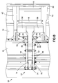
- FIG. 1 is a diagram showing a sectional view of some components and portions of other components of a wing assembly comprising a spar, an upper wing skin, and a smooth bonded metallic leading edge skin panel affixed to and overlapping the upper wing skin.
- FIG. 2 is a diagram showing a top view of a portion of a wing assembly incorporating a plurality of leading edge skin panels having fasteners along adjacent side edge portions and along respective aft edge portions that overlap the wing skin.
- FIG. 2A is a diagram showing a top view (on a magnified scale) of the portion of the wing assembly inside an area 2 A indicated in FIG. 2 .
- FIG. 3A is a diagram showing a sectional view of a lap joint at an aft edge portion of the leading edge skin panel depicted in FIG. 1 in accordance with one embodiment.
- FIG. 3B is a diagram showing a sectional view of a lap joint at an aft edge portion of the leading edge skin panel depicted in FIG. 1 in accordance with an alternative embodiment.
- FIG. 4 is a diagram showing a sectional view of a forward portion of a leading edge assembly incorporating a low-drag bleed-air anti-icing (i.e., vent) system.
- FIG. 4A is a diagram showing a sectional view of the vent system partly depicted in FIG. 4 , the section being taken along line 4 A- 4 A indicated in FIG. 4 .
- FIG. 5 is a diagram showing an isometric view of a forward portion of a leading edge assembly incorporating a vent system.
- FIG. 6 is a diagram showing a side view of a wing leading edge assembly incorporating a Krueger flap assembly. The Krueger flap is shown in an extended position.
- FIG. 7 is a diagram showing a side view of the wing leading edge assembly depicted in FIG. 6 after the removal of a rib.
- FIG. 8 is a diagram showing a bottom view of the wing leading edge assembly depicted in FIG. 6 .
- FIGS. 9 and 10 are diagrams showing respective isometric views of some components of the Krueger flap assembly depicted in FIGS. 6 and 8 .
- FIG. 11 is a diagram showing a side view of a wing leading edge assembly in accordance with an alternative embodiment.
- the Krueger flap is shown in a retracted position.
- a metallic fixed leading edge skin panel that has one or more of the following features: (1) the metallic fixed leading edge skin panel is bonded to internal support structure and overlaps a wing skin; (2) the metallic fixed leading edge skin panel integrates a low-drag bleed-air vent system; and (3) the metallic fixed leading edge skin panel integrates a Krueger flap assembly.
- Laminar flow has tighter wing contour, waviness and step requirements than on current passenger jets.
- a key requirement is to minimize the number of fasteners that protrude through the external leading edge skin to reduce steps and waviness.
- FIG. 1 is a diagram showing a sectional view of some components and portions of other components of a wing assembly in accordance with one embodiment. Some components of the wing assembly, such as ribs and a Krueger flap assembly pivotably coupled to those ribs, are not shown.
- FIG. 1 shows one embodiment of a minimal-fastener wing leading edge assembly comprising a metallic fixed leading edge skin panel 2 which is bonded to a metallic sub-structure.
- the metallic sub-structure comprises an upper chord 4 , a lower chord 6 , and a pair of L-shaped stiffener members 8 , 10 .
- Metal bonding is standard practice, but the specific implementation described herein is new.
- the upper chord 4 and the stiffener members 8 , 10 each comprise a flange (e.g., flange 4 a of upper chord 4 ) having tapered edges and a web (e.g., web 4 b of upper chord 4 ) which meet at a thick intersection (e.g., intersection 4 c of upper chord 4 ), which geometry minimizes the bond stresses.
- the fixed leading edge skin panel 2 is moderately thicker than conventional leading edge skin panels to provide deflection control.
- the upper chord 4 and stiffener members 8 , 10 are bonded to an upper portion 2 a of fixed leading edge skin panel 2
- the lower chord 6 is bonded to a lower portion 2 b of fixed leading edge skin panel 2 and extends beyond an aft edge of that lower portion.
- the lower chord 6 may be L-shaped, as seen in FIG. 1 , or inverted T-shaped (e.g., ⁇ -shaped), as seen in FIG. 4 .
- a nose beam web 12 is fastened by a multiplicity of fasteners 30 to the webs of upper chord 4 and lower chord 6 to form a bulkhead (e.g., forward bulkhead 13 ) that defines a cavity 14 in the forwardmost portion of the leading edge assembly.
- a bleed-air duct 16 is disposed within the cavity 14 .
- the bleed-air duct 16 is in fluid communication with a source of hot bleed air (not shown), e.g., an aircraft engine.
- the bleed-air duct 16 has one or more openings (not shown) that allow hot bleed air inside the duct to escape into the cavity 14 for use in de-icing surfaces, (e.g., the lower surface of the wind leading edge assembly), as will be described in more detail later with reference to FIGS. 4 and 5 .
- the fixed leading edge skin panel 2 , upper chord 4 , lower chord 6 , stiffener members 8 , 10 , and nose web beam 12 are made of materials that have very similar coefficients of thermal expansion, which minimizes thermally-induced deflections (e.g., all aluminum or all titanium work better than assembly of aluminum and titanium parts).
- the wing assembly partly depicted in FIG. 1 further comprises a front spar 18 , an upper wing skin 20 joined to an upper portion 18 a of the front spar 18 , and a lower wing skin 22 joined to a lower portion 18 b of the front spar 18 .
- the wing assembly may further include ribs, which are fixedly coupled to and extend between the nose beam web 12 and the front spar 18 (not shown in FIG. 1 for clarity, but see rib 42 in FIG. 7 and ribs 40 , 42 in FIG. 8 , as examples).
- the upper wing skin 20 is connected to an upper portion of the front spar 18 and includes a forward extension 32 that extends forward of the front spar 18 .
- the forward extension 32 and the aft edge portion 3 of the upper portion 2 a of fixed leading edge skin panel 2 are coupled to each other by a row of fasteners 24 a , only one fastener of which is visible in FIG. 1 .
- a plurality of fixed leading edge skin panels may be arranged side-by-side along the leading edge of a wing.
- Each fixed leading edge skin panel 2 is fastened (e.g., bolted) at both ends (hereinafter “side edge portions”) and along the aft edge portion.
- FIG. 2 shows a first fixed leading edge skin panel 2 adjacent to a second fixed leading edge skin panel 2 ′.
- Fixed leading edge skin panels 2 and 2 ′ have respectively rows of fasteners 24 b along respective side edge portions and respective rows of fasteners 24 a along respective aft edge portions that overlap the wing skin 20 .
- FIG. 2A shows a top view (on a magnified scale) of the portion of the wing assembly inside an area 2 A indicated in FIG. 2 . Referring to FIG.
- the aft edge portions of the fixed leading edge skin panels 2 and 2 ′ and the forward extension 32 of the upper wing skin 20 are fixedly coupled to the sub-structure by means of fasteners 24 a .
- the side edge portions of the fixed leading edge skin panels 2 and 2 ′ are fixedly coupled to the sub-structure by fasteners 24 b .
- the occasional rows of fasteners 24 b will create a turbulent zone (i.e., a turbulent flow cone, as indicated by two diverging dashed-dotted lines in FIG. 2A ) that results in increased drag, but this is deemed an acceptable laminar flow compromise to enable an easily buildable and safe design.
- a stiffener member or upper chord bond failure will be contained (but is detectable) by the bolted structure at the ends of fixed leading edge skin panels.
- the forward extension 32 of the upper wing skin 20 includes a mating surface 32 a and an inner surface 32 b , the mating surface 32 a being offset from an aerodynamic surface 20 a of the upper wing skin 20 , which offset enables an aft edge portion 3 of the upper portion 2 a of fixed leading edge skin panel 2 to overlap the forward extension 32 in a way (including shimming if needed) such that the aerodynamic surface of the upper portion 2 a of the fixed leading edge skin panel 2 and the aerodynamic surface 20 a of the upper wing skin 20 will be level with each other.
- This joint design minimizes the aerodynamic steps, enabling laminar flow to cross the joint, by overlapping the fixed leading edge skin panel 2 onto the upper wing skin 20 in a simple and stiff lap joint.
- a shim 36 may be inserted between the aft edge portion 3 of the fixed leading edge skin panel 2 and the forward extension 32 of the upper wing skin 20 .
- shim 36 may have a thickness equal, for example, to the difference between the thickness of the aft edge portion 3 of the fixed leading edge skin panel 2 and the height of the offset of the forward extension 32 from the surface of the upper wing skin 20 .
- a shaved insert 34 (made, e.g., of high-performance plastic, carbon-filled epoxy, aluminum-filled epoxy, or other filler) is used for manufacturing tolerance pay-off.
- the skins are built with sufficient accuracy to avoid the insert.
- FIGS. 3A and 3B Another feature of the joint designs shown in FIGS. 3A and 3B is a clip 38 installed below the lap joint which, when removed, allows a pre-assembled fixed leading edge assembly to be installed onto an assembled wing box. In addition, this design allows systems to be installed on the front spar 18 prior to leading edge installation.
- FIG. 4 shows a sectional view of a forward portion of a leading edge assembly incorporating a low-drag bleed-air wing anti-icing or de-icing system.
- This bleed-air wing anti-icing system is integrated with the fixed leading edge skin panel 2 in a way to minimize the impact on the aerodynamic surface.
- Traditionally bleed-air holes are formed on a wing lower surface.
- the fixed leading edge assembly shown in FIG. 4 is designed with a multiplicity of vents 28 formed by respective channels 26 in the flange of the lower chord 6 and/or in the confronting inner surface 27 of the lower portion 2 b of the fixed leading edge skin panel 2 .
- FIG. 4A shows a sectional view of the vent system partly depicted in FIG.
- each channel 26 in the flange of lower chord 6 partly defines a respective vent 28 .
- the channels 26 in the lower chord 6 are spaced apart and mutually parallel.
- vents 28 formed by channels 26 and the confronting inner surface of the lower portion 2 b of the fixed leading edge skin panel 2 are in fluid communication with the ambient atmosphere by way of a gap between the fixed and movable leading edge skin panels (this gap is not shown in FIGS. 4 and 5 ). More specifically, this design bleeds the air through vents 28 and the air exits through a gap 48 (shown in FIG. 11 ) between the aft edge of the lower portion 2 b of the fixed leading edge skin panel 2 and the forward edge of the movable leading edge skin panel 52 , which is part of the Krueger flap (discussed in detail below).
- This design provides more heated surface area on the lower wing surface and more ice removal. In addition, it may provide some ice removal on the surface of the moveable leading edge skin panel 52 .
- the wing leading edge assembly integrates a two-position, high-height, variable-camber Krueger flap assembly of the type described in detail in U.S. patent application Ser. No. 13/867,562.
- a wing leading edge assembly will now be described in more detail herein with reference to FIGS. 6-9 .
- FIG. 6 shows a cross-sectional view of a wing leading edge assembly when the Krueger flap is an extended (i.e., deployed) position.
- a rib 40 is visible in the forefront of FIG. 6 , while a second rib 42 is hidden behind rib 40 .
- FIG. 7 shows an alternate cross-sectional view taken along the same cross section line as in FIG. 6 but after the removal of rib 40 , thereby exposing rib 42 .
- FIG. 9 is an isometric view showing that ribs 40 , 42 are connected by a forward bridge fitting 44 and an aft bridge fitting 46 . Only forward bridge fitting 44 is visible in the bottom view of FIG. 8 , which is partial detail view of the wing leading edge assembly of FIG. 6 from a bottom vantage point looking upward. The bridge fittings 44 , / 46 are also visible in section in FIG. 7 .
- the ribs 40 , 42 are fixedly coupled to the stiffener members 8 , 10 by one or more fasteners, (e.g., fasteners 76 , 78 respectively).
- the ribs 40 , 42 are also fixedly coupled to the nose beam web 12 , to the front spar 18 (by respective rib-spar clips 39 ), and to the forward extension 32 of the upper wing skin 20 (by respective corner clips 38 ).
- Each of the corner clips 38 (only one of which is visible in FIG. 6 ) has a first portion fastened to a respective rib 40 , 42 and a second portion fastened to the forward extension 32 of the upper wing skin 20 .
- Each of the rib-spar clips 39 (only one of which is visible in FIG. 7 ) has a first portion fastened to a respective rib 40 , 42 and a second portion fastened to the front spar 18 .
- the Krueger flap assembly comprises a Krueger flap 50 and a Krueger flap deployment mechanism 51 .
- the Krueger flap 50 comprises an assembly of components, including (but not limited to) a movable lower leading edge skin panel 52 , a bullnose member 54 and a flap link 74 .
- the Krueger flap 50 protects the leading edge of the wing (i.e., fixed upper leading edge skin panel 2 ) from bugs and debris encountered at lower altitudes.
- the Krueger flap deployment mechanism 51 comprises a drive arm 60 integrated with a pair of torque tubes 58 (see FIG. 8 ) having splines on their inside diameters, and a pair of geared rotary actuators 56 (see FIG. 9 ) that provide torque for rotating the drive arm 60 to deploy or retract the Krueger flap 50 .
- the geared rotary actuators 56 are planetary gearboxes.
- the Krueger flap 50 moves from a retracted state (not shown in the drawings) to the deployed state shown in FIG. 7 .
- the Krueger flap 50 stops extending when the drive arm 60 abuts the forward bridge fitting 44 , which functions as a deploy drive arm stop.
- the Krueger flap 50 moves from the deployed state to the retracted state.
- the Krueger flap 50 stops retracting when the tip of drive arm 60 abuts the aft bridge fitting 46 , which functions as a retract drive arm stop.
- the lower chord 6 is provided with cutouts 80 (two of which are shown in FIG. 8 ). Each cutout 80 provides clearance space for a respective support arm 66 to allow full deployment of the Krueger flap 50 . In this manner the lower chord 6 is configured to enable the support arm 66 to pivot to an angular position whereat the drive arm 60 abuts the forward bridge fitting 44 .
- the Krueger flap deployment mechanism 51 further comprises a linkage assembly that couples the flap link 74 of Krueger flap 50 to the drive arm 60 .
- This linkage assembly may be of the type described in detail in U.S. patent application Ser. No. 13/867,562. As best seen in FIGS.
- such a linkage assembly comprises: a pair of drive links 62 , 64 having respective ends pivotably coupled to an intermediate portion of drive arm 60 and respective ends pivotably coupled to flap link 74 near one end thereof; a yoke-shaped support arm 66 pivotably coupled by a pair of rotation joints 82 (on opposite sides of drive arm 60 ) to forward bridge fitting 44 and having a distal end pivotably coupled to respective intermediate portions of drive links 62 , 64 ; and a pair of drive transfer arms 70 , 72 having respective ends pivotably coupled to a distal end of drive arm 60 and respective intermediate portions pivotably coupled to an intermediate portion of flap link 74 .
- the distal end of support arm 66 seen in FIG. 8 does not extend to or contact the flap link 74 .
- FIG. 11 shows a side view of a wing leading edge assembly in accordance with an alternative embodiment in which a composite panel (e.g., a honeycomb core panel 84 ) is used in place of stiffener members.
- the honeycomb core panel 84 is formed with a plurality of potted inserts 86 which accept fasteners for attaching the honeycomb core panel 84 to the ribs 40 , 42 .
- the upper portion 2 a of the fixed leading edge skin panel 2 is bonded to the honeycomb core panel 84 .
- Similar elements in FIGS. 6 and 11 bear the same reference numerals.
- FIG. 11 shows the Krueger flap in a retracted position.
- FIG. 11 also shows a nose beam clip 88 , which is fastened to both the rib 40 and the nose beam web 12 , thereby coupling rib 40 to nose beam web 12 .
- the term “fixedly coupled” means joined by methods other than bonding or welding, while the term “connected” means joined by bonding or welding.
- the corresponding structures disclosed hereinabove for performing the stiffening function include metal chords, metal stiffener members (a.k.a. stringers), honeycomb core panels, and equivalents thereof.
Abstract
A wing leading edge architecture designed to enable laminar flow on passenger jets or other aircraft. The embodiments disclosed herein comprise a metallic fixed leading edge skin panel that is bonded to internal support structure without fasteners except for limited fastening along side edge portions adjacent to side edge portions of adjacent leading edge skin panels and along an aft edge portion overlapping a wing skin. In addition, the embodiments disclosed herein integrate a low-drag bleed-air anti-icing (i.e., vent) system and a Krueger flap assembly (e.g., a two-position, high-height, variable-camber Krueger flap assembly).
Description
This disclosure relates to aircraft boundary-layer flow-control systems, and more specifically, to methods and apparatus for encouraging laminar flow along the surface of an airfoil or body.
Laminar flow along a surface of an airfoil is typically achieved by reducing the magnitude of disturbances and instabilities in the boundary-layer. By keeping these fluctuations small, the nonlinear interactions leading to turbulence can be curtailed and/or delayed. Currently, the most robust methods for controlling the disturbance amplitudes are based on modifying the boundary-layer mean flow via airfoil geometry (i.e., by tailoring the pressure gradient) or by applying surface suction. Since modifications to the pressure gradient do not actively consume power, this approach has been termed “natural laminar flow”. The successful application of this approach and attainment of drag reduction benefits has been demonstrated both theoretically and in testing for nominally two-dimensional boundary layers.
Surface discontinuities may disrupt the laminar boundary layer of air over an airfoil (e.g., an aircraft wing) and cause it to become turbulent. A turbulent boundary layer may be characterized by increased mixing between layers of air within the boundary layer. The drag caused by a turbulent boundary layer may be as much as 5 to 10 times greater than the drag of a laminar boundary layer. This transition from laminar flow to turbulent flow within the boundary layer may increase drag. Also, this transition may produce undesirable noise, decrease fuel efficiency, and/or other undesirable effects during flight. These discontinuities may be caused by, for example, without limitation, steps and/or gaps in joints between wing skin panels and/or steps and/or waviness due to fasteners that extend through the skin panels and fasten the panels to the wingbox.
It is well known that systems incorporated in an airfoil for other purposes may contribute to turbulent flow. For example, anti-icing systems are widely used for the prevention of ice buildup on leading edges of aircraft structures. It is known to install a bleed-air wing anti-icing or de-icing system near the leading edge of a wing. The incorporation of an anti-icing system in a wing leading edge may adversely affect airflow in the boundary layer.
In addition, modern aircraft may use a variety of high-lift leading and trailing edge devices to improve high-angle of attack performance during various phases of flight, including takeoff and landing. Existing leading edge devices include leading edge slats and Krueger flaps. Krueger flaps have generally the same function as leading edge slats, but rather than retracting aft to form the leading edge of the cruise wing, Krueger flaps are hinged, and typically fold into the lower surface of the wing when stowed. When deployed, Krueger flaps extend forward from the under surface of the wing, increasing the wing camber and maximum coefficient of lift. In the case of a typical Krueger flap, a slot or gap is created between the flap and the wing as the flap is extended forward. During certain operating conditions, air can flow through this slot to energize the airflow over the upper surface of the wing, and improve overall airflow characteristics over the wing. A two-position, high-height, variable-camber Krueger flap assembly is disclosed in U.S. patent application Ser. No. 13/867,562, the disclosure of which is incorporated by reference herein in its entirety.
A wing leading edge structure that encourages laminar flow, integrates a bleed-air anti-icing system, and further integrates a two-position, high-height, variable-camber Krueger flap would be useful.
The subject matter disclosed herein is a wing leading edge architecture designed to enable laminar flow on passenger jets and other aircraft. The embodiments disclosed herein comprise a metallic fixed leading edge skin panel that is bonded or welded to internal support structure with limited use of fasteners along side edge portions and along an aft edge portion overlapping an upper wing skin. In addition, the embodiments disclosed herein integrate a low-drag bleed-air anti-icing (i.e., vent) system and a Krueger flap assembly (e.g., a two-position, high-height, variable-camber Krueger flap assembly).
As used hereinafter, the term “fixedly coupled” means joined by any means other than bonding or welding (e.g., fastening), while the term “connected” means joined by bonding or welding.
One aspect of the subject matter disclosed in detail below is a wing assembly comprising: a spar; an upper wing skin joined to the spar, the upper wing skin comprising a forward extension that extends forward of the spar and includes a mating surface offset from a surface of the upper wing skin; a first rib fixedly coupled to and projecting forward from the spar; a fixed leading edge skin panel fixedly coupled to the first rib, wherein the fixed leading edge skin panel comprises an upper portion having an aft edge portion that overlaps the forward extension such that a surface of the fixed leading edge skin panel is level with the surface of the upper wing skin. This wing assembly may further comprise first and second pluralities of fasteners disposed along left and right side edges respectively of the upper portion of the fixed leading edge skin panel, and a third plurality of fasteners disposed along an aft edge of an upper portion of the fixed leading edge skin panel.
The wing assembly described in the preceding paragraph may further comprise one or more of the following elements: (1) a shim disposed between the aft edge portion of the upper portion of the fixed leading edge skin panel and the forward extension of the upper wing skin. (2) an insert made of polymeric material, the insert being disposed in a space bounded by an aft edge of the aft edge portion of the upper portion of the fixed leading edge skin panel, the forward extension of the upper wing skin, and an offset wall of the upper wing skin; (3) a clip comprising a vertical portion fixedly coupled to the first rib and a horizontal portion fixedly coupled to the forward extension of the upper wing skin; (4) a stiffener member fixedly coupled to the first rib and connected to the upper portion of the fixed leading edge skin panel, wherein the stiffener member comprises a web and a flange which meet at an intersection, the flange being tapered on both sides of the intersection; and (5) an upper chord connected to the upper portion of the fixed leading edge skin panel, wherein the upper chord comprises a web and a flange which meet at an intersection, the flange being tapered on both sides of the intersection.
In accordance with one embodiment, the wing assembly described above further comprises an upper chord connected to the upper portion of the fixed leading edge skin panel, a lower chord connected to a lower portion of the fixed leading edge skin panel, a nose beam web fixedly coupled to the upper and lower chords, and a plurality of vents formed by the lower portion of the fixed leading edge skin panel and the lower chord. The first rib is fixedly coupled to the nose beam web. The lower chord comprises a plurality of channels, the vents being formed by the channels and opposing portions of the lower portion of the fixed leading edge skin panel. The fixed leading edge skin panel and the nose beam web define a cavity in fluid communication with the vents, the wing assembly further comprising a duct in fluid communication with the cavity and a source of hot air. This embodiment further comprises: a second rib fixedly coupled to the spar, to the nose beam web, and to the fixed leading edge skin panel; first and second bridge fittings fixedly coupled to and extending between the first and second ribs; and a Krueger flap assembly pivotably coupled to the first and second ribs. The Krueger flap assembly comprises a movable lower leading edge skin panel and a mechanism that abuts the first bridge fitting when the movable lower leading edge panel is in an extended position and abuts the second bridge fitting when the movable lower leading edge skin panel is in a retracted position. The lower chord has a cutout for clearance with the mechanism of the Krueger flap assembly when the movable lower leading edge skin panel is in the extended position.
Another aspect of the subject matter disclosed in detail below is a wing assembly comprising: a fixed leading edge skin panel comprising upper and lower portions; and a bulkhead connected to the upper and lower portions of the fixed leading edge skin panel to define a cavity, wherein the bulkhead comprises a lower flange connected to the lower portion of the fixed leading edge skin panel, which lower flange comprises a plurality of channels for venting air from the cavity. The bulkhead may comprise an upper chord connected to the upper portion of the fixed leading edge skin panel, a lower chord connected to the lower portion of the fixed leading edge skin panel, and a nose beam web fixedly coupled to the upper and lower chords, wherein the lower flange is part of the lower chord. This wing assembly may further comprise: first and second ribs fixedly coupled to the bulkhead; and a Krueger flap assembly pivotably coupled to the first and second ribs. The Krueger flap assembly comprises a movable lower leading edge skin panel having a forward portion that overlaps an aft portion of the lower chord when the movable lower leading edge skin panel is in a retracted position, and a mechanism capable of moving the movable lower leading edge skin panel from the retracted position to an extended position in response to actuation. An aft edge of the lower portion of the fixed leading edge skin panel is separated from a forward edge of the movable lower leading edge skin panel by a gap when the movable lower leading edge skin panel is in the retracted position, the gap being in fluid communication with the plurality of channels.
A further aspect is a wing assembly comprising: a spar; first and second ribs fixedly coupled to and projecting forward from the spar; a fixed leading edge skin panel comprising upper and lower portions; and means for stiffening the wing assembly, the means for stiffening being connected to the fixed leading edge skin panel and fixedly coupled to the first and second ribs. The means for stiffening may be made of metal or honeycomb core. This wing assembly may further comprise an upper chord connected to the upper portion of the fixed leading edge skin panel, a lower chord connected to a lower portion of the fixed leading edge skin panel, and a nose beam web fixedly coupled to the upper and lower chords and to the first and second ribs. In accordance with one embodiment, the upper chord comprises a web and a flange which meet at an intersection, the flange being tapered on both sides of the intersection. Again the wing assembly may further comprise a Krueger flap assembly pivotably coupled to the first and second ribs. This Krueger flap assembly comprises: a movable lower leading edge skin panel having a forward portion that overlaps an aft portion of the lower chord when the movable lower leading edge skin panel is in a retracted position; and a mechanism capable of moving the movable lower leading edge skin panel from the retracted position to an extended position in response to actuation.
Other aspects of wing assemblies suitable for laminar flow are disclosed below.
Reference will hereinafter be made to the drawings in which similar elements in different drawings bear the same reference numerals.
Various illustrative embodiments of wing leading edge assemblies that encourage laminar flow will now be described in detail. In accordance with the embodiments disclosed in detail below, a metallic fixed leading edge skin panel is provided that has one or more of the following features: (1) the metallic fixed leading edge skin panel is bonded to internal support structure and overlaps a wing skin; (2) the metallic fixed leading edge skin panel integrates a low-drag bleed-air vent system; and (3) the metallic fixed leading edge skin panel integrates a Krueger flap assembly.
Laminar flow has tighter wing contour, waviness and step requirements than on current passenger jets. A key requirement is to minimize the number of fasteners that protrude through the external leading edge skin to reduce steps and waviness.
More specifically, FIG. 1 shows one embodiment of a minimal-fastener wing leading edge assembly comprising a metallic fixed leading edge skin panel 2 which is bonded to a metallic sub-structure. In accordance with this embodiment, the metallic sub-structure comprises an upper chord 4, a lower chord 6, and a pair of L-shaped stiffener members 8, 10. Metal bonding is standard practice, but the specific implementation described herein is new. The upper chord 4 and the stiffener members 8, 10 each comprise a flange (e.g., flange 4 a of upper chord 4) having tapered edges and a web (e.g., web 4 b of upper chord 4) which meet at a thick intersection (e.g., intersection 4 c of upper chord 4), which geometry minimizes the bond stresses. The fixed leading edge skin panel 2 is moderately thicker than conventional leading edge skin panels to provide deflection control.
Still referring to FIG. 1 , the upper chord 4 and stiffener members 8, 10 are bonded to an upper portion 2 a of fixed leading edge skin panel 2, whereas the lower chord 6 is bonded to a lower portion 2 b of fixed leading edge skin panel 2 and extends beyond an aft edge of that lower portion. The lower chord 6 may be L-shaped, as seen in FIG. 1 , or inverted T-shaped (e.g., ⊥-shaped), as seen in FIG. 4 . A nose beam web 12 is fastened by a multiplicity of fasteners 30 to the webs of upper chord 4 and lower chord 6 to form a bulkhead (e.g., forward bulkhead 13) that defines a cavity 14 in the forwardmost portion of the leading edge assembly. A bleed-air duct 16 is disposed within the cavity 14. The bleed-air duct 16 is in fluid communication with a source of hot bleed air (not shown), e.g., an aircraft engine. The bleed-air duct 16 has one or more openings (not shown) that allow hot bleed air inside the duct to escape into the cavity 14 for use in de-icing surfaces, (e.g., the lower surface of the wind leading edge assembly), as will be described in more detail later with reference to FIGS. 4 and 5 .
The fixed leading edge skin panel 2, upper chord 4, lower chord 6, stiffener members 8, 10, and nose web beam 12 (as well as ribs 40, 42 seen in FIG. 8 ) are made of materials that have very similar coefficients of thermal expansion, which minimizes thermally-induced deflections (e.g., all aluminum or all titanium work better than assembly of aluminum and titanium parts).
An alternate approach to metal bonding is to weld the upper chord 4 and stiffener members 8, 10 using a process that has minimal impact on the outer surface, such as friction stir welding, soldering or brazing. Another alternate approach is to use honeycomb core in place of stiffener members. With honeycomb core, the fixed leading edge skin panels may have a variable thickness, using conventional or chemical milling. An embodiment having honeycomb core will be described in more detail later with reference to FIG. 11 .
The wing assembly partly depicted in FIG. 1 further comprises a front spar 18, an upper wing skin 20 joined to an upper portion 18 a of the front spar 18, and a lower wing skin 22 joined to a lower portion 18 b of the front spar 18. The wing assembly may further include ribs, which are fixedly coupled to and extend between the nose beam web 12 and the front spar 18 (not shown in FIG. 1 for clarity, but see rib 42 in FIG. 7 and ribs 40, 42 in FIG. 8 , as examples).
As seen in FIG. 1 , the upper wing skin 20 is connected to an upper portion of the front spar 18 and includes a forward extension 32 that extends forward of the front spar 18. The forward extension 32 and the aft edge portion 3 of the upper portion 2 a of fixed leading edge skin panel 2 are coupled to each other by a row of fasteners 24 a, only one fastener of which is visible in FIG. 1 .
A plurality of fixed leading edge skin panels may be arranged side-by-side along the leading edge of a wing. Each fixed leading edge skin panel 2 is fastened (e.g., bolted) at both ends (hereinafter “side edge portions”) and along the aft edge portion. FIG. 2 shows a first fixed leading edge skin panel 2 adjacent to a second fixed leading edge skin panel 2′. Fixed leading edge skin panels 2 and 2′ have respectively rows of fasteners 24 b along respective side edge portions and respective rows of fasteners 24 a along respective aft edge portions that overlap the wing skin 20. FIG. 2A shows a top view (on a magnified scale) of the portion of the wing assembly inside an area 2A indicated in FIG. 2 . Referring to FIG. 2A , the aft edge portions of the fixed leading edge skin panels 2 and 2′ and the forward extension 32 of the upper wing skin 20 are fixedly coupled to the sub-structure by means of fasteners 24 a. The side edge portions of the fixed leading edge skin panels 2 and 2′ are fixedly coupled to the sub-structure by fasteners 24 b. The occasional rows of fasteners 24 b will create a turbulent zone (i.e., a turbulent flow cone, as indicated by two diverging dashed-dotted lines in FIG. 2A ) that results in increased drag, but this is deemed an acceptable laminar flow compromise to enable an easily buildable and safe design. Specifically regarding safety, a stiffener member or upper chord bond failure will be contained (but is detectable) by the bolted structure at the ends of fixed leading edge skin panels.
Another novel feature is the over-spar joint design shown in FIG. 1 and shown in more detail in FIG. 3A . The forward extension 32 of the upper wing skin 20 includes a mating surface 32 a and an inner surface 32 b, the mating surface 32 a being offset from an aerodynamic surface 20 a of the upper wing skin 20, which offset enables an aft edge portion 3 of the upper portion 2 a of fixed leading edge skin panel 2 to overlap the forward extension 32 in a way (including shimming if needed) such that the aerodynamic surface of the upper portion 2 a of the fixed leading edge skin panel 2 and the aerodynamic surface 20 a of the upper wing skin 20 will be level with each other. This joint design minimizes the aerodynamic steps, enabling laminar flow to cross the joint, by overlapping the fixed leading edge skin panel 2 onto the upper wing skin 20 in a simple and stiff lap joint.
In accordance with the joint design shown in FIG. 3A , a shim 36 may be inserted between the aft edge portion 3 of the fixed leading edge skin panel 2 and the forward extension 32 of the upper wing skin 20. For example, shim 36 may have a thickness equal, for example, to the difference between the thickness of the aft edge portion 3 of the fixed leading edge skin panel 2 and the height of the offset of the forward extension 32 from the surface of the upper wing skin 20.
Furthermore, in the joint configuration shown in FIG. 3B , a shaved insert 34 (made, e.g., of high-performance plastic, carbon-filled epoxy, aluminum-filled epoxy, or other filler) is used for manufacturing tolerance pay-off. In the joint configuration shown in FIG. 3A , the skins are built with sufficient accuracy to avoid the insert.
Another feature of the joint designs shown in FIGS. 3A and 3B is a clip 38 installed below the lap joint which, when removed, allows a pre-assembled fixed leading edge assembly to be installed onto an assembled wing box. In addition, this design allows systems to be installed on the front spar 18 prior to leading edge installation.
Referring again to FIG. 4 , the aft outlets of vents 28 formed by channels 26 and the confronting inner surface of the lower portion 2 b of the fixed leading edge skin panel 2 are in fluid communication with the ambient atmosphere by way of a gap between the fixed and movable leading edge skin panels (this gap is not shown in FIGS. 4 and 5 ). More specifically, this design bleeds the air through vents 28 and the air exits through a gap 48 (shown in FIG. 11 ) between the aft edge of the lower portion 2 b of the fixed leading edge skin panel 2 and the forward edge of the movable leading edge skin panel 52, which is part of the Krueger flap (discussed in detail below). This design provides more heated surface area on the lower wing surface and more ice removal. In addition, it may provide some ice removal on the surface of the moveable leading edge skin panel 52.
In accordance with a further aspect, the wing leading edge assembly integrates a two-position, high-height, variable-camber Krueger flap assembly of the type described in detail in U.S. patent application Ser. No. 13/867,562. One embodiment of such a wing leading edge assembly will now be described in more detail herein with reference to FIGS. 6-9 .
Referring again to FIG. 6 , the ribs 40, 42 are fixedly coupled to the stiffener members 8, 10 by one or more fasteners, (e.g., fasteners 76, 78 respectively). The ribs 40, 42 are also fixedly coupled to the nose beam web 12, to the front spar 18 (by respective rib-spar clips 39), and to the forward extension 32 of the upper wing skin 20 (by respective corner clips 38). Each of the corner clips 38 (only one of which is visible in FIG. 6 ) has a first portion fastened to a respective rib 40, 42 and a second portion fastened to the forward extension 32 of the upper wing skin 20. Each of the rib-spar clips 39 (only one of which is visible in FIG. 7 ) has a first portion fastened to a respective rib 40, 42 and a second portion fastened to the front spar 18.
As best seen in FIGS. 6 and 7 , the Krueger flap assembly comprises a Krueger flap 50 and a Krueger flap deployment mechanism 51. The Krueger flap 50 comprises an assembly of components, including (but not limited to) a movable lower leading edge skin panel 52, a bullnose member 54 and a flap link 74. In addition to altering aerodynamic performance of the wing when deployed, the Krueger flap 50 protects the leading edge of the wing (i.e., fixed upper leading edge skin panel 2) from bugs and debris encountered at lower altitudes.
The Krueger flap deployment mechanism 51 comprises a drive arm 60 integrated with a pair of torque tubes 58 (see FIG. 8 ) having splines on their inside diameters, and a pair of geared rotary actuators 56 (see FIG. 9 ) that provide torque for rotating the drive arm 60 to deploy or retract the Krueger flap 50. In accordance with one embodiment, the geared rotary actuators 56 are planetary gearboxes.
When the drive arm 60 rotates clockwise (from the vantage point of FIG. 7 ), the Krueger flap 50 moves from a retracted state (not shown in the drawings) to the deployed state shown in FIG. 7 . The Krueger flap 50 stops extending when the drive arm 60 abuts the forward bridge fitting 44, which functions as a deploy drive arm stop. In contrast, when the drive arm 60 rotates counterclockwise (from the vantage point of FIG. 7 ), the Krueger flap 50 moves from the deployed state to the retracted state. The Krueger flap 50 stops retracting when the tip of drive arm 60 abuts the aft bridge fitting 46, which functions as a retract drive arm stop. (During retraction, the tip of drive arm 60 follows a path P indicated by a dashed arc in FIG. 7 .) The lower chord 6 is provided with cutouts 80 (two of which are shown in FIG. 8 ). Each cutout 80 provides clearance space for a respective support arm 66 to allow full deployment of the Krueger flap 50. In this manner the lower chord 6 is configured to enable the support arm 66 to pivot to an angular position whereat the drive arm 60 abuts the forward bridge fitting 44.
The Krueger flap deployment mechanism 51 further comprises a linkage assembly that couples the flap link 74 of Krueger flap 50 to the drive arm 60. This linkage assembly may be of the type described in detail in U.S. patent application Ser. No. 13/867,562. As best seen in FIGS. 7, 8 and 10 , such a linkage assembly comprises: a pair of drive links 62, 64 having respective ends pivotably coupled to an intermediate portion of drive arm 60 and respective ends pivotably coupled to flap link 74 near one end thereof; a yoke-shaped support arm 66 pivotably coupled by a pair of rotation joints 82 (on opposite sides of drive arm 60) to forward bridge fitting 44 and having a distal end pivotably coupled to respective intermediate portions of drive links 62, 64; and a pair of drive transfer arms 70, 72 having respective ends pivotably coupled to a distal end of drive arm 60 and respective intermediate portions pivotably coupled to an intermediate portion of flap link 74. (For the avoidance of doubt, the distal end of support arm 66 seen in FIG. 8 does not extend to or contact the flap link 74.) Further details concerning the structure and operation of the Krueger flap assembly are depicted in FIGS. 6-10 .
While wing leading edge assemblies have been described with reference to various embodiments, changes may be made and equivalents may be substituted for elements thereof without departing from the scope of the claims set forth hereinafter. In addition, many modifications may be made to adapt the teachings herein to a particular situation without departing from the scope of the claims.
As used in the claims, the term “fixedly coupled” means joined by methods other than bonding or welding, while the term “connected” means joined by bonding or welding. With regard to the term “means for stiffening”, the corresponding structures disclosed hereinabove for performing the stiffening function include metal chords, metal stiffener members (a.k.a. stringers), honeycomb core panels, and equivalents thereof.
Claims (18)
1. A wing assembly comprising:
a spar;
an upper wing skin joined to said spar, said upper wing skin comprising a forward extension that extends forward of said spar and includes a mating surface offset from a surface of said upper wing skin;
a first rib fixedly coupled to and projecting forward from said spar;
a fixed leading edge skin panel fixedly coupled to said first rib, wherein said fixed leading edge skin panel comprises an upper portion and a lower portion;
an upper chord connected to said upper portion of said fixed leading edge skin panel;
a lower chord connected to said lower portion of said fixed leading edge skin panel; and
a nose beam web fixedly coupled to said upper and lower chords, wherein said first rib is fixedly coupled to said nose beam web,
wherein said upper portion of said fixed leading edge skin panel is integrally formed with said lower portion and has an aft edge portion that overlaps and is fastened to said forward extension such that a surface of the fixed leading edge skin panel is level with said surface of said upper wing skin.
2. The wing assembly as recited in claim 1 , further comprising a shim disposed between said aft edge portion of said upper portion of said fixed leading edge skin panel and said forward extension of said upper wing skin.
3. The wing assembly as recited in claim 1 , further comprising an insert made of polymeric material, said insert being disposed in a space bounded by an aft edge of said aft edge portion of said upper portion of said fixed leading edge skin panel, said forward extension of said upper wing skin, and an offset wall of said upper wing skin.
4. The wing assembly as recited in claim 1 , further comprising a clip comprising a vertical portion fixedly coupled to said first rib and a horizontal portion fixedly coupled to said forward extension of said upper wing skin.
5. The wing assembly as recited in claim 1 , further comprising a stiffener member fixedly coupled to said first rib and connected to said upper portion of said fixed leading edge skin panel, wherein said stiffener member comprises a web and a flange which meet at an intersection, said flange being tapered on both sides of said intersection.
6. The wing assembly as recited in claim 1 , further comprising an upper chord connected to said upper portion of said fixed leading edge skin panel, wherein said upper chord comprises a web and a flange which meet at an intersection, said flange being tapered on both sides of said intersection.
7. The wing assembly as recited in claim 1 , further comprising a plurality of vents formed by said lower portion of said fixed leading edge skin panel and said lower chord.
8. The wing assembly as recited in claim 7 , wherein said lower chord comprises a plurality of channels, said vents being formed by said channels and opposing portions of said lower portion of said fixed leading edge skin panel.
9. The wing assembly as recited in claim 7 , wherein said fixed leading edge skin panel and said nose beam web define a cavity in fluid communication with said vents, said wing assembly further comprising a duct in fluid communication with said cavity for coupling to a source of hot air.
10. The wing assembly as recited in claim 1 , further comprising:
a second rib fixedly coupled to said spar, to said nose beam web, and to said fixed leading edge skin panel;
first and second bridge fittings fixedly coupled to and extending between said first and second ribs; and
a Krueger flap assembly pivotably coupled to said first and second ribs, wherein said Krueger flap assembly comprises a movable lower leading edge skin panel and a mechanism that abuts said first bridge fitting when said movable lower leading edge panel is in an extended position and abuts said second bridge fitting when said movable lower leading edge skin panel is in a retracted position.
11. The wing assembly as recited in claim 10 , wherein said lower chord has a cutout for clearance with said mechanism of said Krueger flap assembly when said movable lower leading edge skin panel is in said extended position.
12. The wing assembly as recited in claim 1 , further comprising first and second pluralities of fasteners disposed along a left side edge and a right side edge, respectively, of said upper portion of said fixed leading edge skin panel, and a third plurality of fasteners disposed along an aft edge of said upper portion of said fixed leading edge skin panel.
13. A wing assembly comprising:
a fixed leading edge skin panel comprising upper and lower portions;
a bulkhead connected to said upper and lower portions of said fixed leading edge skin panel, wherein said bulkhead and said fixed leading edge skin panel define a cavity forward of said bulkhead, and said bulkhead comprises a lower flange connected to said lower portion of said fixed leading edge skin panel, said lower flange comprising a plurality of channels for venting air from said cavity;
a bleed-air duct disposed within the cavity, said bleed-air duct comprising at least one opening;
first and second ribs fixedly coupled to said bulkhead; and
a Krueger flap assembly pivotably coupled to said first and second ribs, wherein said Krueger flap assembly comprises a movable lower leading edge skin panel having a forward portion that overlaps an aft portion of said lower chord when said movable lower leading edge skin panel is in a retracted position, and a mechanism capable of moving said movable lower leading edge skin panel from said retracted position to an extended position in response to actuation,
wherein an aft edge of said lower portion of said fixed leading edge skin panel is separated from a forward edge of said movable lower leading edge skin panel by a gap when said movable lower leading edge skin panel is in said retracted position, said gap being in fluid communication with said plurality of channels.
14. The wing assembly as recited in claim 13 , wherein said bulkhead further comprises an upper chord connected to said upper portion of said fixed leading edge skin panel, a lower chord connected to said lower portion of said fixed leading edge skin panel, and a nose beam web fixedly coupled to said upper and lower chords, wherein said lower flange is part of said lower chord.
15. A wing assembly comprising: a spar; first and second ribs fixedly coupled to and projecting forward from said spar; a fixed leading edge skin panel comprising upper and lower portions; an upper chord connected to said upper portion of said fixed leading edge skin panel; a lower chord connected to a lower portion of said fixed leading edge skin panel; a nose beam web fixedly coupled to said upper and lower chords and to said first and second ribs; and means for stiffening said wing assembly, said means for stiffening said wing assembly being connected to said upper portion of said fixed leading edge skin panel and fixedly coupled to said first and second ribs, and a Krueger flap assembly pivotably coupled to said first and second ribs, wherein said Krueger flap assembly comprises:
a movable lower leading edge skin panel having a forward portion that overlaps an aft portion of said lower chord when said movable lower leading edge skin panel is in a retracted position; and
a mechanism capable of moving said movable lower leading edge skin panel from said retracted position to an extended position in response to actuation.
16. The wing assembly as recited in claim 15 , wherein said means for stiffening are made of metal, bonded to said fixed leading edge skin panel, and fastened to said first and second ribs.
17. The wing assembly as recited in claim 15 , wherein said means for stiffening are made of honeycomb core, bonded to said fixed leading edge skin panel, and fastened to said first and second ribs.
18. The wing assembly as recited in claim 15 , wherein said upper chord comprises a web and a flange which meet at an intersection, said flange being tapered on both sides of said intersection.
Priority Applications (1)
| Application Number | Priority Date | Filing Date | Title |
|---|---|---|---|
| US14/271,477 US9896190B1 (en) | 2014-05-07 | 2014-05-07 | Wing leading edge architecture suitable for laminar flow |
Applications Claiming Priority (1)
| Application Number | Priority Date | Filing Date | Title |
|---|---|---|---|
| US14/271,477 US9896190B1 (en) | 2014-05-07 | 2014-05-07 | Wing leading edge architecture suitable for laminar flow |
Publications (1)
| Publication Number | Publication Date |
|---|---|
| US9896190B1 true US9896190B1 (en) | 2018-02-20 |
Family
ID=61188282
Family Applications (1)
| Application Number | Title | Priority Date | Filing Date |
|---|---|---|---|
| US14/271,477 Active 2036-07-31 US9896190B1 (en) | 2014-05-07 | 2014-05-07 | Wing leading edge architecture suitable for laminar flow |
Country Status (1)
| Country | Link |
|---|---|
| US (1) | US9896190B1 (en) |
Cited By (11)
| Publication number | Priority date | Publication date | Assignee | Title |
|---|---|---|---|---|
| US20170291687A1 (en) * | 2016-04-11 | 2017-10-12 | Asco Industries NV | High-Lift Device |
| DE102019111135A1 (en) * | 2019-04-30 | 2020-11-05 | Airbus Operations Gmbh | Leading edge device for an aircraft |
| US20210024221A1 (en) * | 2019-07-25 | 2021-01-28 | Airbus Operations Sas | Leading edge member for an airfoil of an aircraft |
| US20210107669A1 (en) * | 2019-08-13 | 2021-04-15 | Airbus Operations Sas | Anterior part of a nacelle for an aircraft propulsion assembly, whose front frame is connected to an outer wall without penetrating it |
| EP3816039A1 (en) * | 2019-11-01 | 2021-05-05 | The Boeing Company | Continuous skin leading edge slats |
| US11286034B2 (en) * | 2018-11-22 | 2022-03-29 | Airbus Operations Gmbh | Leading-edge slat for an aircraft |
| US11377197B2 (en) * | 2019-07-10 | 2022-07-05 | The Boeing Company | High lift systems for aircraft and related methods |
| US11440665B2 (en) * | 2018-10-23 | 2022-09-13 | Airbus Operations Gmbh | Vented leading-edge assembly and method for manufacturing a vented leading-edge assembly |
| EP3683140B1 (en) | 2019-01-18 | 2022-10-12 | Asco Industries NV | Slat for an aircraft wing, method for manufacturing such a slat |
| US11492098B2 (en) * | 2018-03-02 | 2022-11-08 | Mitsubishi Heavy Industries, Ltd. | High-lift device, wing, and aircraft |
| US20240017819A1 (en) * | 2022-07-15 | 2024-01-18 | The Boeing Company | Wing assemblies with three-position krueger flaps and methods of operating three-position krueger flaps |
Citations (33)
| Publication number | Priority date | Publication date | Assignee | Title |
|---|---|---|---|---|
| US3889903A (en) * | 1973-03-09 | 1975-06-17 | Boeing Co | Airfoil leading edge structure with boundary layer control |
| US3910530A (en) * | 1973-11-07 | 1975-10-07 | Boeing Co | Leading edge flap |
| US3941334A (en) * | 1975-03-28 | 1976-03-02 | The Boeing Company | Variable camber airfoil |
| US4099691A (en) * | 1976-12-13 | 1978-07-11 | The Boeing Company | Boundary layer control system for aircraft |
| US4159089A (en) * | 1977-05-31 | 1979-06-26 | Boeing Commercial Airplane Company | Variable camber flap |
| US4285482A (en) * | 1979-08-10 | 1981-08-25 | The Boeing Company | Wing leading edge high lift device |
| US4427168A (en) * | 1981-09-29 | 1984-01-24 | The Boeing Company | Variable camber leading edge mechanism with Krueger flap |
| US4553722A (en) * | 1982-12-30 | 1985-11-19 | The Boeing Company | Variable-camber airfoil |
| US4752049A (en) * | 1985-12-30 | 1988-06-21 | The Boeing Company | Leading edge slat/anti-icing system and method for airfoil |
| US4770607A (en) * | 1987-04-27 | 1988-09-13 | United Technologies Corporation | Rotor blade construction for circulation control aircraft |
| US4813631A (en) * | 1982-09-13 | 1989-03-21 | The Boeing Company | Laminar flow control airfoil |
| US5098037A (en) * | 1989-11-06 | 1992-03-24 | The B. F. Goodrich Company | Structural airfoil having integral expulsive system |
| US5114100A (en) * | 1989-12-29 | 1992-05-19 | The Boeing Company | Anti-icing system for aircraft |
| US5695154A (en) * | 1995-08-21 | 1997-12-09 | Northrop Grumman Corporation | Gap filler device |
| US6129314A (en) * | 1997-01-21 | 2000-10-10 | The B. F. Goodrich Company | Hybrid deicer with element sequence |
| US6283411B1 (en) * | 1998-01-21 | 2001-09-04 | The B.F. Goodrich Company | Hybrid deicer with element sequence control |
| US6467730B2 (en) * | 2000-01-17 | 2002-10-22 | Dassault Aviation | Aircraft airfoil leading edge member equipped with a de-icing device |
| US20070194179A1 (en) * | 2004-03-03 | 2007-08-23 | Giamati Michael J | Aircraft wing with electrothermal deicing and/or anti-icing device |
| US20080121758A1 (en) * | 2004-12-31 | 2008-05-29 | Airbus Espana, S.L. | Reinforced cover for gaps in an aerodynamic contour |
| US20080258008A1 (en) * | 2005-12-20 | 2008-10-23 | Airbus Uk Limited | Joint for Use in Aircraft Construction |
| US7578484B2 (en) * | 2006-06-14 | 2009-08-25 | The Boeing Company | Link mechanisms for gapped rigid krueger flaps, and associated systems and methods |
| US7992822B2 (en) * | 2006-11-20 | 2011-08-09 | Honda Motor Co., Ltd. | Leading edge skin height difference adjusting structure and method of assembling leading edge skin |
| US20120037760A1 (en) * | 2010-08-15 | 2012-02-16 | Koppelman Henry J | Laminar flow panel |
| US8245972B2 (en) * | 2008-12-09 | 2012-08-21 | Alenia Aeronautica S.P.A. | Leading edge for aircraft wings and empennages |
| US8282042B2 (en) * | 2009-06-22 | 2012-10-09 | The Boeing Company | Skin panel joint for improved airflow |
| US20130270392A1 (en) * | 2012-04-17 | 2013-10-17 | Airbus Operations, S.L. | Interface arrangement for aircraft lifting surface |
| US20140131520A1 (en) * | 2012-02-06 | 2014-05-15 | Cessna Aircraft Company | Thermal Insulation Barrier For An Aircraft De-Icing Heater |
| US8844869B2 (en) * | 2010-06-04 | 2014-09-30 | Dassault Aviation | Aircraft structural assembly and associated assembling method |
| US8925870B1 (en) * | 2012-03-09 | 2015-01-06 | The Boeing Company | Morphing wing leading edge |
| EP2886452A1 (en) * | 2013-12-18 | 2015-06-24 | Airbus Operations GmbH | Flow body, method for manufacturing a flow body and aircraft having such a flow body |
| EP2955108A1 (en) * | 2014-06-13 | 2015-12-16 | Airbus Operations GmbH | Leading edge nose structure on the vertical stabilizer of an aircraft |
| US20160068250A1 (en) * | 2014-09-09 | 2016-03-10 | Airbus Defence and Space GmbH | Airfoil portion with a chamber |
| US20160244143A1 (en) * | 2014-09-17 | 2016-08-25 | The Boeing Company | Composite wing edge attachment and method |
-
2014
- 2014-05-07 US US14/271,477 patent/US9896190B1/en active Active
Patent Citations (37)
| Publication number | Priority date | Publication date | Assignee | Title |
|---|---|---|---|---|
| US3889903A (en) * | 1973-03-09 | 1975-06-17 | Boeing Co | Airfoil leading edge structure with boundary layer control |
| US3910530A (en) * | 1973-11-07 | 1975-10-07 | Boeing Co | Leading edge flap |
| US3941334A (en) * | 1975-03-28 | 1976-03-02 | The Boeing Company | Variable camber airfoil |
| US4099691A (en) * | 1976-12-13 | 1978-07-11 | The Boeing Company | Boundary layer control system for aircraft |
| US4159089A (en) * | 1977-05-31 | 1979-06-26 | Boeing Commercial Airplane Company | Variable camber flap |
| US4285482A (en) * | 1979-08-10 | 1981-08-25 | The Boeing Company | Wing leading edge high lift device |
| US4427168A (en) * | 1981-09-29 | 1984-01-24 | The Boeing Company | Variable camber leading edge mechanism with Krueger flap |
| US4813631A (en) * | 1982-09-13 | 1989-03-21 | The Boeing Company | Laminar flow control airfoil |
| US4553722A (en) * | 1982-12-30 | 1985-11-19 | The Boeing Company | Variable-camber airfoil |
| US4752049A (en) * | 1985-12-30 | 1988-06-21 | The Boeing Company | Leading edge slat/anti-icing system and method for airfoil |
| US4770607A (en) * | 1987-04-27 | 1988-09-13 | United Technologies Corporation | Rotor blade construction for circulation control aircraft |
| US5098037A (en) * | 1989-11-06 | 1992-03-24 | The B. F. Goodrich Company | Structural airfoil having integral expulsive system |
| US5114100A (en) * | 1989-12-29 | 1992-05-19 | The Boeing Company | Anti-icing system for aircraft |
| US5695154A (en) * | 1995-08-21 | 1997-12-09 | Northrop Grumman Corporation | Gap filler device |
| US6129314A (en) * | 1997-01-21 | 2000-10-10 | The B. F. Goodrich Company | Hybrid deicer with element sequence |
| US6283411B1 (en) * | 1998-01-21 | 2001-09-04 | The B.F. Goodrich Company | Hybrid deicer with element sequence control |
| US6467730B2 (en) * | 2000-01-17 | 2002-10-22 | Dassault Aviation | Aircraft airfoil leading edge member equipped with a de-icing device |
| US7278610B2 (en) * | 2004-03-03 | 2007-10-09 | Goodrich Corporation | Aircraft wing with electrothermal deicing and/or anti-icing device |
| US7546980B2 (en) * | 2004-03-03 | 2009-06-16 | Goodrich Corporation | Aircraft wing with electrothermal deicing and/or anti-icing device |
| US20070194179A1 (en) * | 2004-03-03 | 2007-08-23 | Giamati Michael J | Aircraft wing with electrothermal deicing and/or anti-icing device |
| US20080121758A1 (en) * | 2004-12-31 | 2008-05-29 | Airbus Espana, S.L. | Reinforced cover for gaps in an aerodynamic contour |
| US20080258008A1 (en) * | 2005-12-20 | 2008-10-23 | Airbus Uk Limited | Joint for Use in Aircraft Construction |
| US7578484B2 (en) * | 2006-06-14 | 2009-08-25 | The Boeing Company | Link mechanisms for gapped rigid krueger flaps, and associated systems and methods |
| US7992822B2 (en) * | 2006-11-20 | 2011-08-09 | Honda Motor Co., Ltd. | Leading edge skin height difference adjusting structure and method of assembling leading edge skin |
| US8245972B2 (en) * | 2008-12-09 | 2012-08-21 | Alenia Aeronautica S.P.A. | Leading edge for aircraft wings and empennages |
| US8282042B2 (en) * | 2009-06-22 | 2012-10-09 | The Boeing Company | Skin panel joint for improved airflow |
| US8844869B2 (en) * | 2010-06-04 | 2014-09-30 | Dassault Aviation | Aircraft structural assembly and associated assembling method |
| US20120037760A1 (en) * | 2010-08-15 | 2012-02-16 | Koppelman Henry J | Laminar flow panel |
| US20140131520A1 (en) * | 2012-02-06 | 2014-05-15 | Cessna Aircraft Company | Thermal Insulation Barrier For An Aircraft De-Icing Heater |
| US8998144B2 (en) * | 2012-02-06 | 2015-04-07 | Textron Innovations Inc. | Thermal insulation barrier for an aircraft de-icing heater |
| US8925870B1 (en) * | 2012-03-09 | 2015-01-06 | The Boeing Company | Morphing wing leading edge |
| US20130270392A1 (en) * | 2012-04-17 | 2013-10-17 | Airbus Operations, S.L. | Interface arrangement for aircraft lifting surface |
| EP2886452A1 (en) * | 2013-12-18 | 2015-06-24 | Airbus Operations GmbH | Flow body, method for manufacturing a flow body and aircraft having such a flow body |
| US20150183513A1 (en) * | 2013-12-18 | 2015-07-02 | Airbus Operations Gmbh | Flow body, method for manufacturing a flow body and aircraft having such a flow body |
| EP2955108A1 (en) * | 2014-06-13 | 2015-12-16 | Airbus Operations GmbH | Leading edge nose structure on the vertical stabilizer of an aircraft |
| US20160068250A1 (en) * | 2014-09-09 | 2016-03-10 | Airbus Defence and Space GmbH | Airfoil portion with a chamber |
| US20160244143A1 (en) * | 2014-09-17 | 2016-08-25 | The Boeing Company | Composite wing edge attachment and method |
Cited By (14)
| Publication number | Priority date | Publication date | Assignee | Title |
|---|---|---|---|---|
| US20170291687A1 (en) * | 2016-04-11 | 2017-10-12 | Asco Industries NV | High-Lift Device |
| US10569859B2 (en) * | 2016-04-11 | 2020-02-25 | Asco Industries NV | High-lift device |
| US11492098B2 (en) * | 2018-03-02 | 2022-11-08 | Mitsubishi Heavy Industries, Ltd. | High-lift device, wing, and aircraft |
| US11440665B2 (en) * | 2018-10-23 | 2022-09-13 | Airbus Operations Gmbh | Vented leading-edge assembly and method for manufacturing a vented leading-edge assembly |
| US11286034B2 (en) * | 2018-11-22 | 2022-03-29 | Airbus Operations Gmbh | Leading-edge slat for an aircraft |
| EP3683140B1 (en) | 2019-01-18 | 2022-10-12 | Asco Industries NV | Slat for an aircraft wing, method for manufacturing such a slat |
| US11459087B2 (en) | 2019-04-30 | 2022-10-04 | Airbus Operations Gmbh | Leading-edge device for an aircraft |
| DE102019111135A1 (en) * | 2019-04-30 | 2020-11-05 | Airbus Operations Gmbh | Leading edge device for an aircraft |
| US11377197B2 (en) * | 2019-07-10 | 2022-07-05 | The Boeing Company | High lift systems for aircraft and related methods |
| US20210024221A1 (en) * | 2019-07-25 | 2021-01-28 | Airbus Operations Sas | Leading edge member for an airfoil of an aircraft |
| US20210107669A1 (en) * | 2019-08-13 | 2021-04-15 | Airbus Operations Sas | Anterior part of a nacelle for an aircraft propulsion assembly, whose front frame is connected to an outer wall without penetrating it |
| EP3816039A1 (en) * | 2019-11-01 | 2021-05-05 | The Boeing Company | Continuous skin leading edge slats |
| US11352124B2 (en) | 2019-11-01 | 2022-06-07 | The Boeing Company | Continuous skin leading edge slats |
| US20240017819A1 (en) * | 2022-07-15 | 2024-01-18 | The Boeing Company | Wing assemblies with three-position krueger flaps and methods of operating three-position krueger flaps |
Similar Documents
| Publication | Publication Date | Title |
|---|---|---|
| US9896190B1 (en) | Wing leading edge architecture suitable for laminar flow | |
| US8622350B1 (en) | Compound leading edge device for aircraft | |
| US8424810B1 (en) | Low noise wing slat system with rigid cove-filled slat | |
| US8342447B2 (en) | Morphing control surface transition | |
| US8556214B2 (en) | Cross-bleed dam | |
| US7258308B2 (en) | Method and apparatus for controlling airflow with a gapped trailing edge device having a flexible flow surface | |
| JP3320072B2 (en) | Aircraft wing assembly | |
| US8579230B2 (en) | Attachment pylon for aircraft turboshaft engine, comprising rear flaps with mobile incidence | |
| US8322655B1 (en) | Twin-boom empennage | |
| US8353478B1 (en) | Blended wing aircraft | |
| US20110163205A1 (en) | Aerofoil accessories and method for modifying the geometry of a wing element | |
| US6123296A (en) | Self-actuated flow control system | |
| EP3243742B1 (en) | Aircraft joint | |
| EP3243744B1 (en) | Aircraft joint | |
| US8061655B1 (en) | Aircraft configuration utilizing fuselage, wing, empennage, and exhaust flow control devices | |
| CN104703878A (en) | Aircraft wing with system establishing a laminar boundary layer flow | |
| EP3181446B1 (en) | Seal | |
| US20160031546A1 (en) | Lift-reducing apparatus for aircraft wings | |
| US20180072401A1 (en) | Wing structure for flying objects | |
| EP2242685B2 (en) | Improved slat configuration for fixed-wing aircraft | |
| US8167249B1 (en) | Controllable upper surface blown nozzle | |
| Pfeiffer | Slotted airfoil with control surface | |
| JP2011519782A (en) | Aircraft fillet fairing with fixed and moving parts, and related systems and methods | |
| US9487287B2 (en) | Wing leading edge venting | |
| US8317129B1 (en) | Universal convergent nozzle and distinct nozzle aperture |
Legal Events
| Date | Code | Title | Description |
|---|---|---|---|
| AS | Assignment |
Owner name: THE BOEING COMPANY, ILLINOIS Free format text: ASSIGNMENT OF ASSIGNORS INTEREST;ASSIGNORS:AMOROSI, STEPHEN R.;SANTINI, GREGORY M.;ANDERSON, MATTHEW LEROY;AND OTHERS;SIGNING DATES FROM 20140429 TO 20140506;REEL/FRAME:032835/0840 |
|
| STCF | Information on status: patent grant |
Free format text: PATENTED CASE |
|
| MAFP | Maintenance fee payment |
Free format text: PAYMENT OF MAINTENANCE FEE, 4TH YEAR, LARGE ENTITY (ORIGINAL EVENT CODE: M1551); ENTITY STATUS OF PATENT OWNER: LARGE ENTITY Year of fee payment: 4 |