EP1962396A2 - Transformatorstation - Google Patents
Transformatorstation Download PDFInfo
- Publication number
- EP1962396A2 EP1962396A2 EP08460006A EP08460006A EP1962396A2 EP 1962396 A2 EP1962396 A2 EP 1962396A2 EP 08460006 A EP08460006 A EP 08460006A EP 08460006 A EP08460006 A EP 08460006A EP 1962396 A2 EP1962396 A2 EP 1962396A2
- Authority
- EP
- European Patent Office
- Prior art keywords
- compartment
- transformer station
- compartments
- transformer
- ventilation slot
- Prior art date
- Legal status (The legal status is an assumption and is not a legal conclusion. Google has not performed a legal analysis and makes no representation as to the accuracy of the status listed.)
- Withdrawn
Links
Images


Classifications
-
- H—ELECTRICITY
- H02—GENERATION; CONVERSION OR DISTRIBUTION OF ELECTRIC POWER
- H02B—BOARDS, SUBSTATIONS OR SWITCHING ARRANGEMENTS FOR THE SUPPLY OR DISTRIBUTION OF ELECTRIC POWER
- H02B7/00—Enclosed substations, e.g. compact substations
- H02B7/06—Distribution substations, e.g. for urban network
Definitions
- the invention provides a transformer station, in particular a movable type, for use in the delivery of electrical power to electric appliances in contaminated and onerous environment.
- the purpose of the invention is to solve the question of safe and long operation of a transformer station by maintaining permissible temperatures inside the transformer station compartments, which are significantly different for individual electrical equipment and apparatus, and to provide for the tightness of the transformer station compartments, while simultaneously meeting the limiting requirement of maintaining the suitable dimensions of the transformer station.
- a transformer station consists of at least two compartments having separate closed housings connected via a common supporting frame and electrical passes, situated side by side at a certain distance, forming a ventilation slot, inside one of the housings a compartment comprising law voltage control and signal instrumentation, inclusive of the power switch, being placed.
- the wall of the compartment housing containing the control and signal instrumentation and facing the ventilation slot is equipped with an insulation cover. It consists of a layer of metal sheet facing the ventilation slot, which constitutes a screen reflecting electromagnetic radiation, specifically infrared radiation, and a layer of insulating foam.
- the compartment housings are situated, side by side, along the side walls.
- the ventilation slot is limited by the side covers, which reinforces the structure connecting the compartments and creates the conditions favoring so called stack draft, i.e. air flow from bottom to top.
- the electrical connections placed in tubular electrical passes located perpendicularly to the side walls forming the ventilation slot provide the control and signal communication between the compartments.
- Each compartment is equipped with doors or hatches with tightening elements, which provide access to the electrical equipment and to the control and signal instrumentation as well as the required tightness.
- the transformer Because of the heat generated by the power transformer, it is necessary to cool the transformer and to lower the temperature inside the housing of the compartments containing the medium voltage electrical equipment with forced air circulation by means of a fan, and to equalize the temperatures in the compartments.
- the covers of the power transformer compartment are equipped with cooling radiators.
- the support frame rests on skids which are used for placing and moving the transformer station.
- a variety of the invention is a transformer station in a housing divided into compartments of electrical equipment, arranged side by side in succession, i.e. power transformer compartment, fan compartment, medium voltage isolating switch compartment and bushing insulators compartment.
- power transformer compartment On the common wall of the bushing insulators compartment and of the medium voltage isolating switch compartment there are gas expansion openings, whereas on the wall separating the medium voltage isolating switch compartment from the fan compartment there is a safety membrane equipped with circumferential seal on its periphery. The safety membrane is pushed out of the opening if there is an arc-type short-circuit and accumulation of gas pressure inside the bushing insulators compartment or in the medium voltage isolating switch compartment.
- the solution of this invention solves the problem of securing the durability of a transformer station and provides a high degree of safety in its operation.
- Providing a separate housing equipped with a ventilation slot for the control and signal instrumentation compartment makes possible adequate protection of the control and signal instrumentation against overheating, and increased thermal tolerance for the remaining compartments containing electrical equipment, which creates prerequisite for tight closure of the doors and hatches with simultaneous application of ventilation of closed circulation of air in the compartments of the power transformer and of the fan.
- suitable dimensions of the station are maintained, which is the condition for using the station in underground mining.
- the solution of the variety of the invention protects against uncontrolled increase of the pressure inside the bushing insulators compartment by allowing the gas to expand into the remaining compartments.
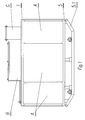
- fig.1 represents a front view of a transformer station
- fig. 2 - a top view of the station
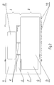
- fig. 3 - a side view of the station with partially exposed compartments
- fig. 4 represents a rear view of the transformer station with partially exposed compartments
- fig. 5 - a top view of the bottom wall of the medium voltage isolating switch compartment.
- a transformer station consists of six compartments situated in two separate housings I and II. On the front side of the transformer station in housing I there is compartment A in which low voltage control and signal instrumentation 1 with a power switch are placed. Located on compartment A is also low voltage connecting compartment B of low voltage leakages. Parallel to housing I there is housing II at a distance of about 1/7 of the width of the transformer station. Between the long side walls of housing I and housing II there is a ventilation slot C. The wall of housing I facing ventilation slot C is equipped with insulation cover 2 consisting of two layers: steel sheet layer 2.1 having the properties of reflecting electromagnetic radiation, especially infrared, and insulating foam layer 2.2. Ventilation slot C is closed by side covers 3 mounted onto the side walls of housing I and II.
- housings I and II are connected by common support frame 5 and the electric passes.
- Housing II contains four compartments: D, E, F, G to be used for locating electrical equipment.
- Compartment D contains power transformer 6; at about 1/2 of its height there is partition 6.1 separating the streams of inlet air and return air.
- Beside compartment D there is separated by wall 6.2 compartment E of fan 7 which blows air through opening 6.3 to compartment D of power transformer 6.
- compartment E there is compartment F of medium voltage isolating switch 8.
- Compartment A in which low voltage control and signal instrumentation 1 and the power switch are placed is equipped with doors with sealing elements, while the remaining compartments are equipped with hatches with sealing elements.
- Support frame 5 rests on skids 5.1.
- the structure of a transformer station is as shown in example 1, housings I and II being situated side by side at a distance of about 1/9 of the width of the transformer station.
- compartment F In the bottom wall of compartment F, on the other hand, there is on opening plugged with safety membrane 8.1 equipped with a circumferential seal on its periphery.
- compartment G Above the compartment there is compartment G of bushing insulators 9.
- the covers of the power transformer compartments are equipped with cooling radiators 10.
- the housings of the compartments are tightly closed against penetration by contaminated air. Because of the heat generated by power transformer 6, fan 7 is switched on and it pushes air to the lower part of power transformer compartment D and cools the winding of power transformer 6. Then air flows through the cooling slots of the windings of power transformer 6 to the upper part of the compartment above separating partition 6.1 and returns to compartment E of fan 7 through inlet opening 6.4. As a result of the heating of the wall of power transformer compartment 6, initiated is the heating of the air space in ventilation slot C from which heat convection with the air flowing from bottom to top takes place. Furthermore, the emitted infrared radiation is reflected from the layer of insulation cover 2, which effectively insulates the wall of compartment wall A containing low voltage control and signal instrumentation 1 against heat transfer.
Landscapes
- Engineering & Computer Science (AREA)
- Power Engineering (AREA)
- Housings And Mounting Of Transformers (AREA)
- Patch Boards (AREA)
Applications Claiming Priority (1)
| Application Number | Priority Date | Filing Date | Title |
|---|---|---|---|
| PL381835A PL206678B1 (pl) | 2007-02-23 | 2007-02-23 | Stacja transformatorowa |
Publications (2)
| Publication Number | Publication Date |
|---|---|
| EP1962396A2 true EP1962396A2 (de) | 2008-08-27 |
| EP1962396A3 EP1962396A3 (de) | 2008-09-03 |
Family
ID=39590239
Family Applications (1)
| Application Number | Title | Priority Date | Filing Date |
|---|---|---|---|
| EP08460006A Withdrawn EP1962396A3 (de) | 2007-02-23 | 2008-02-19 | Transformatorstation |
Country Status (2)
| Country | Link |
|---|---|
| EP (1) | EP1962396A3 (de) |
| PL (1) | PL206678B1 (de) |
Cited By (6)
| Publication number | Priority date | Publication date | Assignee | Title |
|---|---|---|---|---|
| CN104269764A (zh) * | 2014-09-04 | 2015-01-07 | 酒泉华杰电气有限公司 | 光伏发电逆变升压智能箱变 |
| EP3363967A1 (de) * | 2017-02-16 | 2018-08-22 | ABB Schweiz AG | Stromumwandlungsanordnung und methode zur installation einer solchen anordnung |
| RU2678336C1 (ru) * | 2013-12-05 | 2019-01-28 | Машиненфабрик Райнхаузен Гмбх | Электрическая система для трехфазной цепи переменного тока, коммутационное устройство для этой системы и способ эксплуатации коммутационного устройства |
| CN112003140A (zh) * | 2020-09-10 | 2020-11-27 | 湖北网安科技有限公司 | 一种集装箱式变电站 |
| CN113674949A (zh) * | 2021-09-18 | 2021-11-19 | 天长市万福电子有限公司 | 耐高温绝缘性能好的变压器 |
| IT202100017669A1 (it) * | 2021-07-05 | 2023-01-05 | Unareti S P A | Cabina elettrica di trasformazione |
Citations (3)
| Publication number | Priority date | Publication date | Assignee | Title |
|---|---|---|---|---|
| US2394060A (en) | 1942-11-13 | 1946-02-05 | Gen Electric | Cabinet for electrical apparatus |
| EP1326313A1 (de) | 2001-12-19 | 2003-07-09 | Societe Nouvelle Transfix Toulon | Mittelspannungsanlage mit einem Schaltfeld und einemTransformator |
| FR2866162A1 (fr) | 2004-02-11 | 2005-08-12 | Manuf D App Electr De Cahors M | Poste de transformation a bac de retention. |
-
2007
- 2007-02-23 PL PL381835A patent/PL206678B1/pl unknown
-
2008
- 2008-02-19 EP EP08460006A patent/EP1962396A3/de not_active Withdrawn
Patent Citations (3)
| Publication number | Priority date | Publication date | Assignee | Title |
|---|---|---|---|---|
| US2394060A (en) | 1942-11-13 | 1946-02-05 | Gen Electric | Cabinet for electrical apparatus |
| EP1326313A1 (de) | 2001-12-19 | 2003-07-09 | Societe Nouvelle Transfix Toulon | Mittelspannungsanlage mit einem Schaltfeld und einemTransformator |
| FR2866162A1 (fr) | 2004-02-11 | 2005-08-12 | Manuf D App Electr De Cahors M | Poste de transformation a bac de retention. |
Cited By (8)
| Publication number | Priority date | Publication date | Assignee | Title |
|---|---|---|---|---|
| RU2678336C1 (ru) * | 2013-12-05 | 2019-01-28 | Машиненфабрик Райнхаузен Гмбх | Электрическая система для трехфазной цепи переменного тока, коммутационное устройство для этой системы и способ эксплуатации коммутационного устройства |
| CN104269764A (zh) * | 2014-09-04 | 2015-01-07 | 酒泉华杰电气有限公司 | 光伏发电逆变升压智能箱变 |
| EP3363967A1 (de) * | 2017-02-16 | 2018-08-22 | ABB Schweiz AG | Stromumwandlungsanordnung und methode zur installation einer solchen anordnung |
| CN112003140A (zh) * | 2020-09-10 | 2020-11-27 | 湖北网安科技有限公司 | 一种集装箱式变电站 |
| IT202100017669A1 (it) * | 2021-07-05 | 2023-01-05 | Unareti S P A | Cabina elettrica di trasformazione |
| WO2023281363A1 (en) * | 2021-07-05 | 2023-01-12 | Unareti S.P.A. | Electrical transformation substation |
| CN113674949A (zh) * | 2021-09-18 | 2021-11-19 | 天长市万福电子有限公司 | 耐高温绝缘性能好的变压器 |
| CN113674949B (zh) * | 2021-09-18 | 2023-08-08 | 天长市万福电子有限公司 | 耐高温绝缘性能好的变压器 |
Also Published As
| Publication number | Publication date |
|---|---|
| EP1962396A3 (de) | 2008-09-03 |
| PL206678B1 (pl) | 2010-09-30 |
| PL381835A1 (pl) | 2008-09-01 |
Similar Documents
| Publication | Publication Date | Title |
|---|---|---|
| EP1962396A2 (de) | Transformatorstation | |
| US7778013B2 (en) | Arc resistant baffle for reducing arc-flash energy in an electrical enclosure | |
| EP3060857B1 (de) | Wärmeübertragungseinheit für gefährliche orte | |
| JP4921450B2 (ja) | スイッチギヤ | |
| US20100080261A1 (en) | Simulation test system for thermal impact ageing of power transmission insulator | |
| US9338907B2 (en) | Thermally managed enclosure | |
| CN111670613B (zh) | 用于中压驱动器的集成式空气冷却及耐电弧系统 | |
| CN101027951A (zh) | 设备和网络机柜的冷却系统及冷却设备和网络机柜的方法 | |
| JP2004127926A (ja) | 車両バッテリを冷却する方法および装置 | |
| RU2671003C1 (ru) | Сборка из электрических шкафов, содержащая линию электрических шкафов и охлаждающее устройство, подключенное к линии | |
| US10375843B2 (en) | Switchgear exhaust assembly | |
| US20170256922A1 (en) | Switchgear enclosure with interconnected exhaust system | |
| WO2011146600A1 (en) | Arc resistant electrical enclosure | |
| CN100469228C (zh) | 恒温式隔爆箱 | |
| WO2020100183A1 (ja) | ガス絶縁開閉装置 | |
| EP0430394A1 (de) | Heissgasgebläse | |
| US9520698B2 (en) | Outdoor enclosure for power distribution equipment | |
| JP4690874B2 (ja) | 特殊車両用インバータ装置 | |
| CN217334680U (zh) | 一种新型工业防爆控制箱 | |
| CN104390327A (zh) | 三相ptc加热器支架及空调器 | |
| CN118020185A (zh) | 具有至少两个电池模块的电池蓄能器系统 | |
| JP2018113797A (ja) | スイッチギヤ | |
| EP4428457A1 (de) | Wärmepumpensystem | |
| CN106784511B (zh) | 半密封电源系统及汽车 | |
| CN114375349A (zh) | 原子层沉积设备 |
Legal Events
| Date | Code | Title | Description |
|---|---|---|---|
| PUAI | Public reference made under article 153(3) epc to a published international application that has entered the european phase |
Free format text: ORIGINAL CODE: 0009012 |
|
| PUAL | Search report despatched |
Free format text: ORIGINAL CODE: 0009013 |
|
| AK | Designated contracting states |
Kind code of ref document: A2 Designated state(s): AT BE BG CH CY CZ DE DK EE ES FI FR GB GR HR HU IE IS IT LI LT LU LV MC MT NL NO PL PT RO SE SI SK TR |
|
| AX | Request for extension of the european patent |
Extension state: AL BA MK RS |
|
| AK | Designated contracting states |
Kind code of ref document: A3 Designated state(s): AT BE BG CH CY CZ DE DK EE ES FI FR GB GR HR HU IE IS IT LI LT LU LV MC MT NL NO PL PT RO SE SI SK TR |
|
| AX | Request for extension of the european patent |
Extension state: AL BA MK RS |
|
| RAP1 | Party data changed (applicant data changed or rights of an application transferred) |
Owner name: NT POLSKA SP. Z O.O. |
|
| 17P | Request for examination filed |
Effective date: 20090112 |
|
| 17Q | First examination report despatched |
Effective date: 20090318 |
|
| AKX | Designation fees paid | ||
| REG | Reference to a national code |
Ref country code: DE Ref legal event code: 8566 |
|
| RBV | Designated contracting states (corrected) |
Designated state(s): AT BE BG CH CY CZ DE DK EE ES FI FR GB GR HR HU IE IS IT LI LT LU LV MC MT NL NO PL PT RO SE SI SK TR |
|
| STAA | Information on the status of an ep patent application or granted ep patent |
Free format text: STATUS: THE APPLICATION IS DEEMED TO BE WITHDRAWN |
|
| 18D | Application deemed to be withdrawn |
Effective date: 20130903 |