EP1962284A2 - Übertragungsverfahren, Übertragungsvorrichtung und Aufzeichnungsmedium - Google Patents
Übertragungsverfahren, Übertragungsvorrichtung und Aufzeichnungsmedium Download PDFInfo
- Publication number
- EP1962284A2 EP1962284A2 EP08002468A EP08002468A EP1962284A2 EP 1962284 A2 EP1962284 A2 EP 1962284A2 EP 08002468 A EP08002468 A EP 08002468A EP 08002468 A EP08002468 A EP 08002468A EP 1962284 A2 EP1962284 A2 EP 1962284A2
- Authority
- EP
- European Patent Office
- Prior art keywords
- transfer
- slave medium
- master
- slave
- space
- Prior art date
- Legal status (The legal status is an assumption and is not a legal conclusion. Google has not performed a legal analysis and makes no representation as to the accuracy of the status listed.)
- Ceased
Links
- 238000000034 method Methods 0.000 title claims abstract description 39
- 239000012530 fluid Substances 0.000 claims abstract description 49
- 238000003825 pressing Methods 0.000 claims abstract description 29
- 125000006850 spacer group Chemical group 0.000 claims description 64
- 238000007789 sealing Methods 0.000 description 28
- 239000010408 film Substances 0.000 description 24
- 239000000969 carrier Substances 0.000 description 15
- PXHVJJICTQNCMI-UHFFFAOYSA-N nickel Substances [Ni] PXHVJJICTQNCMI-UHFFFAOYSA-N 0.000 description 9
- 239000011800 void material Substances 0.000 description 8
- 230000005415 magnetization Effects 0.000 description 7
- 239000011347 resin Substances 0.000 description 6
- 229920005989 resin Polymers 0.000 description 6
- 239000000758 substrate Substances 0.000 description 6
- 238000004519 manufacturing process Methods 0.000 description 5
- 229910052759 nickel Inorganic materials 0.000 description 5
- 238000001816 cooling Methods 0.000 description 4
- 239000011521 glass Substances 0.000 description 4
- 238000010438 heat treatment Methods 0.000 description 4
- 230000001678 irradiating effect Effects 0.000 description 4
- 238000003754 machining Methods 0.000 description 3
- 230000003287 optical effect Effects 0.000 description 3
- 239000011359 shock absorbing material Substances 0.000 description 3
- 229910000684 Cobalt-chrome Inorganic materials 0.000 description 2
- 239000010952 cobalt-chrome Substances 0.000 description 2
- 230000005347 demagnetization Effects 0.000 description 2
- 239000000696 magnetic material Substances 0.000 description 2
- 239000000463 material Substances 0.000 description 2
- 238000002844 melting Methods 0.000 description 2
- 239000002184 metal Substances 0.000 description 2
- 229910052751 metal Inorganic materials 0.000 description 2
- 239000010409 thin film Substances 0.000 description 2
- 229910001149 41xx steel Inorganic materials 0.000 description 1
- 229910000531 Co alloy Inorganic materials 0.000 description 1
- 229910002441 CoNi Inorganic materials 0.000 description 1
- -1 CoPtCr Inorganic materials 0.000 description 1
- 229910000640 Fe alloy Inorganic materials 0.000 description 1
- 229910002546 FeCo Inorganic materials 0.000 description 1
- 229910002545 FeCoNi Inorganic materials 0.000 description 1
- 229910005335 FePt Inorganic materials 0.000 description 1
- 229910001030 Iron–nickel alloy Inorganic materials 0.000 description 1
- 229910000990 Ni alloy Inorganic materials 0.000 description 1
- 229910000943 NiAl Inorganic materials 0.000 description 1
- 229920000459 Nitrile rubber Polymers 0.000 description 1
- NPXOKRUENSOPAO-UHFFFAOYSA-N Raney nickel Chemical compound [Al].[Ni] NPXOKRUENSOPAO-UHFFFAOYSA-N 0.000 description 1
- 238000006243 chemical reaction Methods 0.000 description 1
- 238000004140 cleaning Methods 0.000 description 1
- 239000013078 crystal Substances 0.000 description 1
- 230000007423 decrease Effects 0.000 description 1
- 230000003247 decreasing effect Effects 0.000 description 1
- 238000009826 distribution Methods 0.000 description 1
- 239000000428 dust Substances 0.000 description 1
- 238000011156 evaluation Methods 0.000 description 1
- 230000001747 exhibiting effect Effects 0.000 description 1
- 230000004907 flux Effects 0.000 description 1
- 230000001939 inductive effect Effects 0.000 description 1
- 238000000059 patterning Methods 0.000 description 1
- 238000005549 size reduction Methods 0.000 description 1
- 239000000126 substance Substances 0.000 description 1
Images




Classifications
-
- G—PHYSICS
- G11—INFORMATION STORAGE
- G11B—INFORMATION STORAGE BASED ON RELATIVE MOVEMENT BETWEEN RECORD CARRIER AND TRANSDUCER
- G11B5/00—Recording by magnetisation or demagnetisation of a record carrier; Reproducing by magnetic means; Record carriers therefor
- G11B5/86—Re-recording, i.e. transcribing information from one magnetisable record carrier on to one or more similar or dissimilar record carriers
- G11B5/865—Re-recording, i.e. transcribing information from one magnetisable record carrier on to one or more similar or dissimilar record carriers by contact "printing"
Definitions
- the present invention relates to a transfer method, transfer apparatus, and recording medium for transferring, from a master carrier having microscopic asperities formed thereon, one of the asperities and transfer information represented by the asperities onto a slave medium.
- Servo signals for tracking, address information signals, reproduction clock signals, and the like are preformatted and recorded on a magnetic disk at predetermined intervals to perform tracking servo control for a magnetic head.
- the recording can also be performed by a magnetic head
- batch transfer from a master disk serving as a master carrier having format information and address information written thereon is more efficient and preferable.
- a magnetic transfer method in which a master disk having a magnetic layer with an asperity pattern corresponding to information to be transferred is prepared for a slave disk serving as a slave medium which is a high-density magnetic recording medium, a magnetic layer of the slave disk is initially magnetized in one direction along tracks, and then a transfer magnetic field is applied to the magnetic layer in a direction almost opposite to the initial magnetization direction while the initially magnetized slave disk and master disk are in close contact (see, e.g., Japanese Patent Application Laid-Open No. 2001-14667 ).
- a surface thereof needs to be patterned into a predetermined shape.
- an imprinting method in which a master disk (stamper) having a predetermined pattern formed thereon is pressed against a slave disk to transfer the pattern on the master disk onto the slave disk is used, as in the mass production of small electronic devices or optical devices.
- a master carrier may be deformed at the time of pressing to cause a difference between a pattern on the master carrier and a transferred pattern, depending on the machining accuracy of the members.
- Fluid pressurization is conceivable as a method for uniformly pressing a master carrier regardless of machining accuracy.
- a master carrier directly pressed by fluid may be deformed.
- the flexible film may be deformed, consequently, the master carrier may also be deformed because the deformed flexible film drags the master carrier by friction. Therefore, use of the method without change is difficult.
- the present invention has been made in consideration of the above-described problems, and has as its object to provide a transfer method, transfer apparatus, and recording medium for reproducing, with fidelity, asperities formed on a master carrier or transfer information represented by the asperities on a slave medium without deforming the master carrier.
- a master carrier on which microscopic asperities are formed into close contact with a slave medium by pressing the master carrier by pressure of fluid in a direct manner or an indirect manner through a flexible film, and transferring the asperities or transfer information represented by the asperities onto the slave medium, deformation of the master carrier or the flexible film in a pressed region where the pressure by the fluid is applied is prevented, and transfer is performed while the master carrier is in close contact with the slave medium.
- master carriers on which asperities are formed are brought into close contact with a surface of a slave medium.
- the slave medium whose surface is in close contact with the master carriers is placed in a closed container, and fluid such as compressed air is enclosed in the container.
- the master carrier is uniformly pressed all over surface by the enclosed fluid in a direct manner or an indirect manner through a flexible film which is in close contact with the master carrier and is brought into close contact with the slave medium.
- the deformation of the master carrier or the flexible film in the pressed region is prevented by adjusting a width of a space left in an in-plane direction of the slave medium and a width of a space left in a thickness direction of the slave medium.
- widths of slight space left in an in-plane direction of the slave medium and a thickness direction of the slave medium are adjusted to be small.
- the width of the space left in the in-plane direction of the slave medium may be adjusted to be not more than five times a thickness of the master carrier or the flexible film.
- the width of the space left in the thickness direction of the slave medium may be adjusted to be not more than 0.2 mm.
- the space left in the in-plane direction of the slave medium is a space left between the slave medium and a spacer which is arranged in an inner periphery or an outer periphery of the slave medium at the time of transfer and has a shape corresponding to a shape of the inner periphery of the slave medium or a shape corresponding to a shape of the outer periphery of the slave medium, and the width of the space left in the in-plane direction of the slave medium is adjusted based on the shape of the spacer.
- a size of a shape of the inner periphery of the spacer arranged in the inner periphery of a slave medium and a size of a shape of the outer periphery of the spacer arranged in the outer periphery of the slave medium are selected based on the size of the slave medium in the corresponding region.
- the space left in an in-plane direction of the slave medium is adjusted to reduce deformation of the flexible film or the master carrier at a portion corresponding to the space in the in-plane direction, and it becomes possible to transfer the asperities on the master carrier or transfer information represented by the asperities onto the slave medium with fidelity in the order of nanometers.
- the space left in the thickness direction of the slave medium is a space left between the master carrier and the flexible film, and the width of the space is adjusted based on a thickness of the spacer arranged in the one of the inner periphery and the outer periphery of the slave medium at the time of transfer.
- a thickness of a spacer arranged in an inner periphery of the slave medium and a thickness of a spacer arranged in an outer periphery of the slave medium are selected based on thicknesses of the master carrier and the slave medium.
- the space left in the thickness direction of the slave medium is adjusted to reduce deformation of the flexible film at a portion corresponding to the space in the thickness direction, and it becomes possible to transfer the asperities on the master carrier or transfer information represented by the asperities onto the slave medium with fidelity in the order of nanometers.
- the space left in the thickness direction of the slave medium is a space left between the master carrier and the slave medium, and the width of the space is adjusted based on a thickness of the spacer arranged in the inner periphery or the outer periphery of the slave medium at the time of transfer.
- a thickness of the spacer arranged in the inner periphery of the slave medium and a thickness of the spacer arranged in the outer periphery of the slave medium are selected based on a thickness of the slave medium.
- the space left in the thickness direction of the slave medium is adjusted to reduce deformation of a master carrier at a portion corresponding to the space in the thickness direction, and it becomes possible to transfer the asperities on the master carrier or transfer information represented by the asperities onto the slave medium with fidelity in the order of nanometers.
- the width of the space left in the in-plane direction of the slave medium is adjusted by a position where an edge of the master carrier or the flexible film is fixed.
- the master carrier or the flexible film is fixed by adhesion or the like at a position where the width of the space left in the in-plane direction of the slave medium becomes not more than five times a thickness of the master carrier or the flexible film.
- the space left in the in-plane direction of the slave medium is adjusted to reduce deformation of the master carrier or the flexible film at a portion corresponding to the space in the in-plane direction, and it becomes possible to transfer the asperities on the master carrier or the transfer information represented by the asperities onto the slave medium with fidelity in the order of nanometers.
- FIG. 1 is a perspective view of a main portion of a magnetic transfer apparatus 20 for performing magnetic transfer using master disks 10 as master carriers.
- slave surfaces (magnetic recording surfaces) of a slave disk 14 as a slave medium after initial DC magnetization (to be described later) shown in Fig. 3A are made to contact information bearing surfaces 13 of the master disks 10 as the master carriers and are brought into close contact with the information bearing surfaces 13 by a predetermined pressing force. While the slave disk 14 and master disks 10 are in close contact with each other, transfer magnetic fields are applied by a magnetic field generating device 30 to magnetically transfer asperity patterns P as pieces of transfer information formed on the master disks 10 onto the slave disk 14.
- the slave disk 14 is a disk-shaped recording medium such as a hard disk or flexible disk which has magnetic recording layers formed on two surfaces. Before being brought into contact with the master disks 10, the slave disk 14 is subjected as needed to cleaning processing (e.g., varnishing) for removing microscopic projections or dust at the surfaces by a glide head, abrasive body, or the like.
- cleaning processing e.g., varnishing
- Coated magnetic recording layers, plated magnetic recording layers, or metal thin-film magnetic recording layers can be adopted as the magnetic recording layers of the slave disk 14.
- Available magnetic materials for a metal thin-film magnetic recording layer include Co, Co alloys (e.g., CoPtCr, CoCr, CoPtCrTa, CoPtCrNbTa, CoCrB, and CoNi), Fe, Fe alloys (e.g., FeCo, FePt, and FeCoNi), Ni, and Ni alloys (e.g., NiFe). These substances are preferable because they each have a high magnetic flux density and a magnetic anisotropy in the same direction as that of an applied magnetic field (in-plane direction in the case of in-plane recording), which allow clear transfer.
- a non-magnetic underlayer it is preferable to provide a non-magnetic underlayer to give a required magnetic anisotropy under the magnetic material (to the side of a support). It is necessary to make the crystal structure and lattice constant of the underlayer coincide with those of magnetic layers 12.
- the magnetic field generating device 30 for applying transfer magnetic fields has electromagnet devices 34, each composed of a core 32 having a gap 31 extending in the radial direction of a combination of the slave disk 14 and master disks 10 that are held in close contact with each other and a coil 33 wound therearound, on two sides of the combination to apply transfer magnetic fields whose lines G (see Fig. 2 ) of magnetic force are in the same direction along tracks.
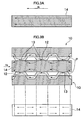
- Fig. 2 is a view showing the relationship between circumferential tracks 14A and the lines G of magnetic force.
- transfer magnetic fields are applied by the magnetic field generating device 30 while integrally rotating the slave disk 14 and master disks 10, thereby magnetically transferring pieces of transfer information represented by asperity patterns on the master disks 10 onto the slave surfaces of the slave disk 14.
- the magnetic field generating device may be rotationally moved instead of the above-described configuration.
- each transfer magnetic field there is generated, in a portion of a track, a magnetic field having a magnetic field intensity distribution in which there is no magnetic field intensity exceeding the upper limit of an optimum transfer magnetic field intensity range (0.6 to 1.3 times a coercive force Hc of the slave disk 14) in any direction along tracks, the magnetic field intensity is within the optimum transfer magnetic field intensity range at least one position in one direction along the tracks, and the magnetic field intensity is less than the lower limit of the optimum transfer magnetic field intensity range at any position in the opposite direction along the tracks.
- Figs. 3A and 3B are views for explaining basic processes of a magnetic transfer method using in-plane recording.
- an initial magnetic field Hi is applied to the slave disk 14 in one direction along the tracks in advance to subject the slave disk 14 to initial magnetization (DC demagnetization).
- each recording surface (magnetic recording portion) of the slave disk 14 and the information bearing surface 13 of the corresponding master disk 10 having the asperity pattern P formed thereon are then brought into close contact with each other, and a transfer magnetic field Hd is applied in a direction along the tracks of the slave disk 14 opposite to that for the initial magnetic field Hi, thereby performing magnetic transfer.
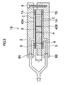
- FIG. 4 is a sectional view showing a first embodiment of a transfer method and transfer apparatus according to the present invention.
- a transfer apparatus 1 A is divided into a container upper portion 2 and a container lower portion 3.
- the container upper and lower portions 2 and 3 unite together with a fastening device 9 such as a bolt or air cylinder.
- a joint 8A which serves as an inlet for fluid supplied to bring a master carrier into close contact with a slave medium.
- a joint 8B is also provided at the container lower portion 3.
- Pipes connected to the joints 8A and 8B branch from a common pipe connected to a fluid source (not shown) as a pressure device which generates fluid such as compressed air. With this configuration, fluids with a single pressure are respectively supplied to the container upper portion 2 and container lower portion 3 through the joints 8A and 8B.
- Master disks 10A and 10B serving as master carriers and a slave disk 14 serving as a slave medium are housed in the container upper portion 2 and container lower portion 3 such that information bearing surfaces of the master disks 10A and 10B are in close contact with two respective surfaces of the slave disk 14.
- a columnar inside spacer 5 having an external shape corresponding to the shapes of the inner sides (center portion) of the slave disk 14 and master disks 10A and 10B is arranged.
- a ring-shaped outside spacer 6 having an internal shape corresponding to the external shapes of outer side (periphery portion) of the slave disk 14 and master disks 10A and 10B is arranged.
- Sealing members 7A and 7B made of, e.g., nitrile rubber, are respectively provided above and below the outside spacer 6.
- Sheets 4A and 4B which are flexible films made of, e.g., a stainless material or PET resin for pressing the master disks 10A and 10B are respectively held between the outside spacer 6 and the sealing members 7A and 7B.
- the slave disk 14 and master disks 10A and 10B are housed between the sheets 4A and 4B such that the master disks 10A and 10B are in close contact with the two surfaces of the slave disk 14.
- the outside diameter of the inside spacer 5 is equal to or slightly smaller than the inside diameters of the slave disk 14 and master disks 10A and 10B, and a space A is left between the inside spacer 5 and the slave disk 14 and master disks 10A and 10B.
- the inside diameter of the outside spacer 6 is equal to or slightly larger than the outside diameters of the slave disk 14 and master disks 10A and 10B, and a space B is left between the outside spacer 6 and the slave disk 14 and master disks 10A and 10B.
- Thicknesses t of the inside spacer 5 and outside spacer 6 are equal to or slightly larger than the sum of the thicknesses of the slave disk 14 and master disks 10A and 10B, and spaces C are left between the sheet 4A and the master disk 10A and between the sheet 4B and the master disk 10B.
- the outside diameter of the inside spacer 5 and the inside diameter of the outside spacer 6 are selected based on the inside and outside diameters of the slave disk 14 and master disks 10A and 10B such that the width of each of the spaces A and B is adjusted to not more than five times the thickness of the sheet 4A or 4B.
- the thicknesses t of the inside spacer 5 and outside spacer 6 are selected not to be larger than the sum of the thicknesses of the slave disk 14 and master disks 10A and 10B by more than 0.2 mm.
- the width of each space C is adjusted to not more than 0.2 mm.
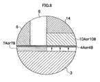
- Fig. 8 is an enlarged sectional view showing a fixed state in the first embodiment of the present invention.
- the width of a portion of the sheet 4A or 4B, the portion is unfixed and adjacent to the space B may be set to not more than five times the thickness of the sheet 4A or 4B.
- the container upper portion 2 and container lower portion 3 are first coupled together by the fastening device 9. This operation forms a void surrounded by the container upper portion 2, sealing member 7A, and sheet 4A and a void surrounded by the container lower portion 3, sealing member 7B, and sheet 4B.
- the pressing force of the fluid is transmitted to the master disks 10A and 10B through the sheets 4A and 4B, and the pressed master disks 10A and 10B come into close contact with the slave disk 14 with predetermined pressing forces. Since the pressing forces are produced by fluid, pressurization is uniform over the pressed regions. In addition, since the fluid is supplied from a single pipeline, the pressing forces applied to master disks 10A and 10B in close contact with the two surfaces of the slave disk 14 are equal.
- the sheets 4A and 4B are adjusted such that they do not cave in toward the adjusted spaces A and B and that the amount of deformation in each pressed region is small.
- the sheets 4A and 4B are also adjusted such that the amount of deformation at a portion corresponding to each space C is small. Accordingly, the sheets 4A and 4B press the master disks 10A and 10B without excessively deforming the master disks 10A and 10B in the pressed regions.
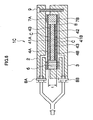
- FIG. 5 is a sectional view showing the second embodiment.
- a transfer apparatus 1B is divided into a container upper portion 2 and a container lower portion 3.
- the container upper and lower portions 2 and 3 unite together with a fastening device 9.
- a joint 8A which serves as an inlet for fluid.
- a joint 8B is also provided at the container lower portion 3.
- Pipes connected to the joints 8A and 8B branch from a common pipe connected to a fluid source (not shown). With this configuration, fluids with a single pressure are respectively supplied to the container upper portion 2 and container lower portion 3 through the joints 8A and 8B.
- Master disks 40A and 40B serving as master carriers and a slave disk 14 serving as a slave medium are housed in the container upper portion 2 and container lower portion 3 such that the slave disk 14 is sandwiched between the master disks 40A and 40B.
- a columnar inside spacer 5 is arranged in the center of the slave disk 14, and a ring-shaped outside spacer 6 is arranged around the outer periphery of the slave disk 14. Sealing members 7A and 7B are respectively provided above and below the outside spacer 6. Edges of the master disks 40A and 40B are held by the outside spacer 6 and sealing members 7A and 7B.
- the outside diameter of the inside spacer 5 is equal to or slightly smaller than the inside diameter of the slave disk 14, and a space A is left between the inside spacer 5 and the slave disk 14.
- the inside diameter of the outside spacer 6 is equal to or slightly larger than the outside diameter of the slave disk 14, and a space B is left between the outside spacer 6 and the slave disk 14.
- Thicknesses t of the inside spacer 5 and outside spacer 6 are equal to or slightly larger than the thickness of the slave disk 14, and spaces C are left between the slave disk 14 and the master disks 40A and 40B.
- the outside diameter of the inside spacer 5 and the inside diameter of the outside spacer 6 are selected based on the inside and outside diameters of the slave disk 14 such that the width of each of the spaces A and B is adjusted to not more than five times the thickness of the master disk 40A or 40B.
- the thicknesses t of the inside spacer 5 and outside spacer 6 are selected not to be larger than the thickness of the slave disk 14 by more than 0.2 mm.
- the width of each space C is adjusted to not more than 0.2 mm.
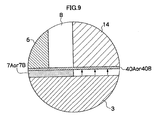
- Fig. 9 is an enlarged sectional view showing a fixed state in the second embodiment of the present invention.
- the width of a portion of the master disk 40A or 40B, the portion is unfixed and adjacent to the space B may be set to not more than five times the thickness of the master disk 40A or 40B.
- the container upper portion 2 and container lower portion 3 are first coupled together by the fastening device 9. This operation forms a void surrounded by the container upper portion 2, sealing member 7A, and master disk 40A and a void surrounded by the container lower portion 3, sealing member 7B, and master disk 40B.
- the pressed master disks 40A and 40B come into close contact with the slave disk 14 with predetermined pressing forces. Since the pressing forces are produced by fluid, pressurization is uniform over the pressed regions. In addition, since the fluid is supplied from a single pipeline, the pressing forces applied to the master disks 40A and 40B in close contact with the two surfaces of the slave disk 14 are equal.
- the master disks 40A and 40B are adjusted such that they do not cave in toward the adjusted spaces A and B and that the amount of deformation in each pressed region is small.
- the master disks 40A and 40B are also adjusted such that the amount of deformation at a portion corresponding to each space C is small.
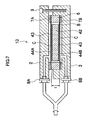
- FIG. 6 is a sectional view showing the third embodiment.
- a transfer apparatus 1C is divided into a container upper portion 2 and a container lower portion 3.
- the container upper and lower portions 2 and 3 unite together with a fastening device 9.
- a joint 8A which serves as an inlet for fluid is provided.
- a joint 8B is also provided at the container lower portion 3.
- Pipes connected to the joints 8A and 8B branch from a common pipe connected to a fluid source (not shown). With this configuration, fluids with a single pressure are respectively supplied to the container upper portion 2 and container lower portion 3 through the joints 8A and 8B.
- Master disks 41A and 41B serving as master carriers and a slave disk 42 serving as a slave medium are housed in the container upper portion 2 and container lower portion 3 such that the master disks 41 A and 41 B are in close contact with two respective surfaces of the slave disk 42.
- transfer layers 43 made of a resin which is cured by light, heat, or the like or low-melting glass, etc., are provided on the two surfaces of the slave disk 42. Asperities on the master disks 41A and 41B corresponding to the shapes of recording bits or the like are satisfactorily transferred onto the transfer layers 43 by irradiating with light, heating, or cooling the transfer layers 43 while the master disks 41A and 41B are pressed against the transfer layers 43 or after the master disks 41A and 41B are peeled from the transfer layers 43.
- a ring-shaped outside spacer 6 is arranged around the outer peripheries of the slave disk 42 and master disks 41A and 41B. Sealing members 7A and 7B are respectively provided above and below the outside spacer 6. Sheets 4A and 4B which are flexible films are respectively held between the outside spacer 6 and the sealing members 7A and 7B.
- the slave disk 42 and master disks 41A and 41B are housed between the sheets 4A and 4B such that the master disks 41A and 41B are in close contact with the transfer layers 43 on the two surfaces of the slave disk 42.
- the inside diameter of the outside spacer 6 is equal to or slightly larger than the outside diameters of the slave disk 42 and master disks 41A and 41B, and a space B is left between the outside spacer 6 and the slave disk 42 and master disks 41A and 41B.
- Thicknesses t of the outside spacer 6 are equal to or slightly larger than the sum of the thicknesses of the slave disk 42, master disks 41A and 41B, and transfer layers 43. In addition, spaces C are left between the sheet 4A and the master disk 41A and between the sheet 4B and the master disk 41B.
- the inside diameter of the outside spacer 6 is selected based on the outside diameters of the slave disk 42 and master disks 41A and 41B such that the width of the space B is adjusted to not more than five times the thickness of the sheet 4A or 4B.
- the thickness t of the outside spacer 6 is selected not to be larger than the sum of the thicknesses of the slave disk 42, master disks 41A and 41B, and transfer layers 43 by more than 0.2 mm.
- the width of each space C is adjusted to not more than 0.2 mm.
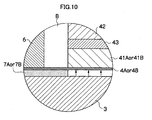
- Fig. 10 is an enlarged sectional view showing a fixed state in the third embodiment of the present invention.
- the width of a portion of the sheet 4A or 4B, the portion is unfixed and adjacent to the space B may be set to not more than five times the thickness of the sheet 4A or 4B.
- the container upper portion 2 and container lower portion 3 are first coupled together by the fastening device 9. This operation forms a void surrounded by the container upper portion 2, sealing member 7A and sheet 4A, and a void surrounded by the container lower portion 3, sealing member 7B and sheet 4B.
- the pressing force of the fluid is transmitted to the master disks 41A and 41B through the sheets 4A and 4B, and the pressed master disks 41 A and 41B come into close contact with the transfer layers 43 with predetermined pressing forces. Since the pressing forces are produced by fluid, pressurization is uniform over the pressed regions. In addition, since the fluid is supplied from a single pipeline, the pressing forces applied to the master disks 41A and 41B in close contact with the transfer layers 43 are equal.
- the sheets 4A and 4B are adjusted such that they do not cave in toward the adjusted space B and that the amount of deformation in each pressed region is small.
- the sheets 4A and 4B are also adjusted such that the amount of deformation at a portion corresponding to each adjusted space C is small. Accordingly, the sheets 4A and 4B press the master disks 41A and 41B without excessively deforming the master disks 41A and 41B in the pressed regions.
- the asperities formed on the master disks 41 A and 41B are transferred onto the transfer layers 43, against which the master disks 41A and 41B are pressed.
- the transfer layers 43 are cured by irradiating with light, heating, or cooling the transfer layers 43 while the master disks 41A and 41B are pressed against the transfer layers 43 or after the master disks 41A and 41B are peeled from the transfer layers 43.
- the asperities as pieces of transfer information are transferred onto the slave disk 42, which becomes a recording medium.
- FIG. 7 is a sectional view showing the fourth embodiment.
- a transfer apparatus 1D is divided into a container upper portion 2 and a container lower portion 3.
- the container upper and lower portions 2 and 3 unite together with a fastening device 9.
- a joint 8A which serves as an inlet for fluid is provided.
- a joint 8B is also provided at the container lower portion 3.
- Pipes connected to the joints 8A and 8B branch from a common pipe connected to a fluid source (not shown). With this configuration, fluids with a single pressure are respectively supplied to the container upper portion 2 and container lower portion 3 through the joints 8A and 8B.
- Master disks 44A and 44B serving as master carriers and a slave disk 42 serving as a slave medium are housed in the container upper portion 2 and container lower portion 3 such that the slave disk 42 is sandwiched between the master disks 44A and 44B.
- Transfer layers 43 made of, a resin which is cured by light, heat, or the like or low-melting glass, etc., are provided on the two surfaces of the slave disk 42. Asperities on the master disks 44A and 44B corresponding to the shapes of recording bits or the like are satisfactorily transferred onto the transfer layers 43 by irradiating with light, heating, or cooling the transfer layers 43 while the master disks 44A and 44B are pressed against the transfer layers 43 or after the master disks 44A and 44B are peeled from the transfer layers 43.
- a ring-shaped outside spacer 6 is arranged around the outer periphery of the slave disk 42. Sealing members 7A and 7B are respectively provided above and below the outside spacer 6. Edges of the master disks 44A and 44B are held by the outside spacer 6 and sealing members 7A and 7B.
- the inside diameter of the outside spacer 6 is equal to or slightly larger than the outside diameter of the slave disk 42, and a space B is left between the outside spacer 6 and the slave disk 42.
- a thickness t of the outside spacer 6 is equal to or slightly larger than the sum of the thicknesses of the slave disk 42 and transfer layers 43, and spaces C are left between the slave disk 42 and the master disks 44A and 44B.
- the inside diameter of the outside spacer 6 is selected based on the outside diameter of the slave disk 42 such that the width of the space B is adjusted to not more than five times the thickness of the master disk 44A or 44B.
- the thickness t of the outside spacer 6 is selected not to be larger than the sum of the thicknesses of the slave disk 42 and transfer layers 43 by more than 0.2 mm.
- the width of each space C is adjusted to not more than 0.2 mm.
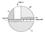
- Fig. 11 is an enlarged sectional view showing a fixed state in the fourth embodiment of the present invention.
- the width of a portion of the master disk 44A or 44B, the portion is unfixed and adjacent to the space B may be set to not more than five times the thickness of the master disk 44A or 44B.
- the container upper portion 2 and container lower portion 3 are first coupled together by the fastening device 9. This operation forms a void surrounded by the container upper portion 2, sealing member 7A and master disk 44A, and a void surrounded by the container lower portion 3, sealing member 7B and master disk 44B.
- the pressed master disks 44A and 44B come into close contact with the transfer layers 43 with predetermined pressing forces. Since the pressing forces are produced by fluid, pressurization is uniform over the pressed regions. In addition, since the fluid is supplied from a single pipeline, the pressing forces applied to the master disks 44A and 44B in close contact with the transfer layers 43 are equal.
- the master disks 44A and 44B are adjusted such that they do not cave in toward the adjusted space B and that the amount of deformation in each pressed region is small.
- the master disks 44A and 44B are also adjusted such that the amount of deformation at a portion corresponding to each adjusted space C is small.
- Asperities formed on the master disks 44A and 44B are transferred onto the transfer layers 43, against which the master disks 44A and 44B are pressed.
- the transfer layers 43 are cured by irradiating with light, heating, or cooling the transfer layers 43 while the master disks 44A and 44B are pressed against the transfer layers 43 or after the master disks 44A and 44B are peeled from the transfer layers 43.
- the asperities as pieces of transfer information are transferred onto the slave disk 42, which becomes a recording medium.
- Fig. 12 is a chart showing data obtained when pieces of transfer information represented by asperities formed on the master disks 10A and 10B were transferred by the transfer apparatus 1A shown in Fig. 4 .
- master carriers for magnetic transfer (inside diameter: 20.0 mm, outside diameter: 65.0 mm, thickness: 0.30 mm) were used for each slave medium (inside diameter: 20.0 mm, outside diameter: 65.0 mm, thickness: 0.50 mm) which was manufactured by a known manufacturing method and was subjected to initial DC magnetization.
- the thicknesses of flexible films were set to 0.1 mm.
- Six combinations of the outside diameter and thickness of an inside spacer, the inside diameter and thickness of an outside spacer, the widths of spaces around the inner and outer peripheries of a slave medium, and the width of a space in the thickness direction of the slave medium were prepared, as shown in Fig. 12 . Air with a pressure of 0.2 MPa was supplied, magnetic transfer was performed by a transfer method according to the present invention, and track signals were transferred from the master carriers onto the slave medium.
- the out-of-roundness was not more than 500 nm, which is a threshold value for identifying good products.
- Pieces of transfer information represented by asperities formed on the master disks 40A and 40B were transferred by the transfer apparatus 1B shown in Fig. 5 .
- an inside spacer was configured to have an outside diameter of 19.95 mm and a thickness of 0.53 mm
- an outside spacer was configured to have an inside diameter of 65.05 mm and a thickness of 0.53 mm
- the out-of-roundness was 343 nm.
- a nickel substrate having a thickness of 0.2 mm and a diameter of 65 mm on which a circular pattern concentric with the nickel substrate having a line width of 100 nm and a height of 100 nm was provided was used as each master carrier, and a glass substrate having a thickness of 0.5 mm and a diameter of 65 mm which was spin-coated with light-curing resin was used as a slave medium.
- Films of PET resin having a thickness of 0.1 mm were additionally used as flexible films, an outside spacer was configured to have an inside diameter of 65.05 mm and a thickness of 0.53 mm, and the pressure of air to be supplied was set to 0.1 MPa. Under these conditions, transfer of the circular pattern onto the slave medium was performed while pressing the master carriers against the slave medium. A satisfactory result was obtained: the out-of-roundness of the transferred circular pattern measured by the roundness measuring machine was 220 nm.
- a nickel substrate having a thickness of 0.3 mm and a diameter of 65 mm on which a circular pattern concentric with the nickel substrate having a line width of 100 nm and a height of 100 nm was provided was used as each master carrier, and a glass substrate having a thickness of 0.5 mm and a diameter of 65 mm which was spin-coated with light-curing resin was used as a slave medium.
- An outside spacer was configured to have an inside diameter of 65.05 mm and a thickness of 0.53 mm, and the pressure of air to be supplied was set to 0.1 MPa. Under these conditions, transfer of the circular pattern onto the slave medium was performed while pressing the master carriers against the slave medium. A satisfactory result was obtained: the out-of roundness of the transferred circular pattern measured by the roundness measuring machine was 480 nm.
Landscapes
- Manufacturing Of Magnetic Record Carriers (AREA)
- Casting Or Compression Moulding Of Plastics Or The Like (AREA)
- Application Of Or Painting With Fluid Materials (AREA)
Applications Claiming Priority (1)
| Application Number | Priority Date | Filing Date | Title |
|---|---|---|---|
| JP2007031120A JP2008198273A (ja) | 2007-02-09 | 2007-02-09 | 転写方法、転写装置、及び記録媒体 |
Publications (2)
| Publication Number | Publication Date |
|---|---|
| EP1962284A2 true EP1962284A2 (de) | 2008-08-27 |
| EP1962284A3 EP1962284A3 (de) | 2009-04-08 |
Family
ID=39493755
Family Applications (1)
| Application Number | Title | Priority Date | Filing Date |
|---|---|---|---|
| EP08002468A Ceased EP1962284A3 (de) | 2007-02-09 | 2008-02-11 | Übertragungsverfahren, Übertragungsvorrichtung und Aufzeichnungsmedium |
Country Status (3)
| Country | Link |
|---|---|
| US (1) | US7804654B2 (de) |
| EP (1) | EP1962284A3 (de) |
| JP (1) | JP2008198273A (de) |
Cited By (1)
| Publication number | Priority date | Publication date | Assignee | Title |
|---|---|---|---|---|
| WO2011050817A1 (en) * | 2009-11-02 | 2011-05-05 | Danmarks Tekniske Universitet | Method and device for nanoimprint lithography |
Citations (2)
| Publication number | Priority date | Publication date | Assignee | Title |
|---|---|---|---|---|
| JP2001014667A (ja) | 1999-04-26 | 2001-01-19 | Fuji Photo Film Co Ltd | 磁気転写方法および磁気転写装置 |
| JP2004086995A (ja) | 2002-08-27 | 2004-03-18 | Fuji Photo Film Co Ltd | 磁気転写装置のホルダー |
Family Cites Families (24)
| Publication number | Priority date | Publication date | Assignee | Title |
|---|---|---|---|---|
| DE1303008B (de) * | 1962-07-02 | |||
| US3499134A (en) * | 1968-06-13 | 1970-03-03 | Litton Precision Prod Inc | Encoder having pin shaped contact elements |
| US4054383A (en) | 1976-02-02 | 1977-10-18 | International Business Machines Corporation | Jig and process for contact printing |
| US6433944B1 (en) * | 1998-09-25 | 2002-08-13 | Fuji Photo Film Co., Ltd. | Master carrier for magnetic transfer and method for transfer |
| US6636371B1 (en) | 1999-04-26 | 2003-10-21 | Fuji Photo Film Co., Ltd. | Magnetic transfer method and system |
| SE515607C2 (sv) | 1999-12-10 | 2001-09-10 | Obducat Ab | Anordning och metod vid tillverkning av strukturer |
| SG92760A1 (en) | 2000-03-29 | 2002-11-19 | Fuji Photo Film Co Ltd | Magnetic transfer method and system |
| US7322287B2 (en) | 2000-07-18 | 2008-01-29 | Nanonex Corporation | Apparatus for fluid pressure imprint lithography |
| US7632434B2 (en) * | 2000-11-17 | 2009-12-15 | Wayne O. Duescher | Abrasive agglomerate coated raised island articles |
| JP3953765B2 (ja) * | 2001-04-16 | 2007-08-08 | 富士フイルム株式会社 | 磁気転写装置 |
| KR20020086291A (ko) * | 2001-05-11 | 2002-11-18 | 후지 샤신 필름 가부시기가이샤 | 자기전사용 마스터담체 |
| US6906875B2 (en) * | 2001-05-15 | 2005-06-14 | Fuji Photo Film Co., Ltd. | Magnetic transfer device |
| CN1253857C (zh) * | 2001-06-21 | 2006-04-26 | 富士胶片株式会社 | 磁复制装置 |
| KR20030001315A (ko) * | 2001-06-25 | 2003-01-06 | 후지 샤신 필름 가부시기가이샤 | 자기전사용 마스터담체 |
| JP3727603B2 (ja) * | 2002-03-15 | 2005-12-14 | 富士写真フイルム株式会社 | 磁気転写装置のホルダー |
| CA2380114C (en) | 2002-04-04 | 2010-01-19 | Obducat Aktiebolag | Imprint method and device |
| JP2004079060A (ja) * | 2002-08-14 | 2004-03-11 | Fuji Photo Film Co Ltd | 磁気転写用マスター担体 |
| US20040040668A1 (en) | 2002-08-27 | 2004-03-04 | Fuji Photo Film Co., Ltd. | Holder for magnetic transfer device |
| JP2004171673A (ja) * | 2002-11-20 | 2004-06-17 | Fuji Photo Film Co Ltd | 磁気転写装置 |
| JP2004241023A (ja) * | 2003-02-04 | 2004-08-26 | Fuji Photo Film Co Ltd | 磁気転写用マスター担体 |
| JP2004253015A (ja) * | 2003-02-18 | 2004-09-09 | Fuji Photo Film Co Ltd | 磁気転写用マスター担体 |
| EP1538482B1 (de) | 2003-12-05 | 2016-02-17 | Obducat AB | Gerät und Methode für grossflÀ¤chige Lithographie |
| US7294441B2 (en) * | 2003-12-31 | 2007-11-13 | Samsung Electronics Co., Ltd. | Method and apparatus for using a transfer assist layer in a tandem electrophotographic process utilizing adhesive toner transfer |
| US7281920B2 (en) | 2005-03-28 | 2007-10-16 | Komag, Inc. | Die set utilizing compliant gasket |
-
2007
- 2007-02-09 JP JP2007031120A patent/JP2008198273A/ja active Pending
-
2008
- 2008-02-08 US US12/028,540 patent/US7804654B2/en not_active Expired - Fee Related
- 2008-02-11 EP EP08002468A patent/EP1962284A3/de not_active Ceased
Patent Citations (2)
| Publication number | Priority date | Publication date | Assignee | Title |
|---|---|---|---|---|
| JP2001014667A (ja) | 1999-04-26 | 2001-01-19 | Fuji Photo Film Co Ltd | 磁気転写方法および磁気転写装置 |
| JP2004086995A (ja) | 2002-08-27 | 2004-03-18 | Fuji Photo Film Co Ltd | 磁気転写装置のホルダー |
Cited By (1)
| Publication number | Priority date | Publication date | Assignee | Title |
|---|---|---|---|---|
| WO2011050817A1 (en) * | 2009-11-02 | 2011-05-05 | Danmarks Tekniske Universitet | Method and device for nanoimprint lithography |
Also Published As
| Publication number | Publication date |
|---|---|
| US20090034108A1 (en) | 2009-02-05 |
| US7804654B2 (en) | 2010-09-28 |
| JP2008198273A (ja) | 2008-08-28 |
| EP1962284A3 (de) | 2009-04-08 |
Similar Documents
| Publication | Publication Date | Title |
|---|---|---|
| US6791774B1 (en) | Contact magnetic transfer of servo pattern to rigid perpendicular magnetic recording disk | |
| US20050111124A1 (en) | Master carrier for magnetic transfer | |
| US6804070B2 (en) | Magnetic transfer apparatus | |
| KR100665001B1 (ko) | 자기전사방법 | |
| US6906876B2 (en) | Magnetic transfer method and apparatus | |
| US7804654B2 (en) | Transfer method, transfer apparatus, and recording medium | |
| US6772507B2 (en) | Method of manufacturing magnetic recording medium | |
| JP4046480B2 (ja) | 磁気転写方法および磁気転写装置 | |
| US7532420B2 (en) | Master disk for magnetic transfer, magnetic recording medium and magnetic recording apparatus | |
| US20070217047A1 (en) | Master medium for perpendicular magnetic transfer, method of perpendicular magnetic transfer, perpendicular magnetic recording medium and perpendicular magnetic recording apparatus | |
| JP3986951B2 (ja) | 磁気転写用マスター担体および磁気転写方法 | |
| JP2008108403A (ja) | 転写方法、転写装置、及び記録媒体 | |
| US20080192587A1 (en) | Transfer apparatus, transfer method, recording medium, and magnetic recording apparatus | |
| JP2004348795A (ja) | 磁気転写方法および磁気転写装置 | |
| US20020171957A1 (en) | Magnetic transfer method and apparatus | |
| JP4195873B2 (ja) | 磁気転写用マスター担体及びその検査方法並びにそれを用いた磁気記録媒体の製造方法 | |
| JP4089904B2 (ja) | 磁気記録媒体の製造方法 | |
| JP3964452B2 (ja) | 磁気転写用マスター担体 | |
| EP1501081A1 (de) | Urträger für magnetische Übertragung, Inspektionsverfahren dafür und Magnetaufzeichnungsmedium-Herstellungsverfahren | |
| JP3999709B2 (ja) | 磁気転写用マスター担体および磁気転写方法 | |
| JP2007299461A (ja) | サーボ信号検査方法、磁気記録媒体及び磁気記録再生装置 | |
| JP2003173513A (ja) | 磁気転写用マスター担体および磁気転写用マスター担体の作製方法 | |
| JP2003228829A (ja) | 磁気転写方法 | |
| JP2006172580A (ja) | 磁気転写方法、磁気転写装置および垂直磁気記録媒体 | |
| JP2005190510A (ja) | 磁気転写方法および磁気転写装置 |
Legal Events
| Date | Code | Title | Description |
|---|---|---|---|
| PUAI | Public reference made under article 153(3) epc to a published international application that has entered the european phase |
Free format text: ORIGINAL CODE: 0009012 |
|
| AK | Designated contracting states |
Kind code of ref document: A2 Designated state(s): AT BE BG CH CY CZ DE DK EE ES FI FR GB GR HR HU IE IS IT LI LT LU LV MC MT NL NO PL PT RO SE SI SK TR |
|
| AX | Request for extension of the european patent |
Extension state: AL BA MK RS |
|
| PUAL | Search report despatched |
Free format text: ORIGINAL CODE: 0009013 |
|
| AK | Designated contracting states |
Kind code of ref document: A3 Designated state(s): AT BE BG CH CY CZ DE DK EE ES FI FR GB GR HR HU IE IS IT LI LT LU LV MC MT NL NO PL PT RO SE SI SK TR |
|
| AX | Request for extension of the european patent |
Extension state: AL BA MK RS |
|
| 17P | Request for examination filed |
Effective date: 20091007 |
|
| AKX | Designation fees paid |
Designated state(s): DE FR GB |
|
| 17Q | First examination report despatched |
Effective date: 20100121 |
|
| STAA | Information on the status of an ep patent application or granted ep patent |
Free format text: STATUS: THE APPLICATION HAS BEEN REFUSED |
|
| 18R | Application refused |
Effective date: 20121108 |