EP1962066B1 - Dispositif de mesure de niveau d'un fluide - Google Patents
Dispositif de mesure de niveau d'un fluide Download PDFInfo
- Publication number
- EP1962066B1 EP1962066B1 EP08158367.6A EP08158367A EP1962066B1 EP 1962066 B1 EP1962066 B1 EP 1962066B1 EP 08158367 A EP08158367 A EP 08158367A EP 1962066 B1 EP1962066 B1 EP 1962066B1
- Authority
- EP
- European Patent Office
- Prior art keywords
- waveguide
- tank
- transducer
- fluid
- measurement
- Prior art date
- Legal status (The legal status is an assumption and is not a legal conclusion. Google has not performed a legal analysis and makes no representation as to the accuracy of the status listed.)
- Active
Links
Images


Classifications
-
- G—PHYSICS
- G01—MEASURING; TESTING
- G01F—MEASURING VOLUME, VOLUME FLOW, MASS FLOW OR LIQUID LEVEL; METERING BY VOLUME
- G01F23/00—Indicating or measuring liquid level or level of fluent solid material, e.g. indicating in terms of volume or indicating by means of an alarm
- G01F23/22—Indicating or measuring liquid level or level of fluent solid material, e.g. indicating in terms of volume or indicating by means of an alarm by measuring physical variables, other than linear dimensions, pressure or weight, dependent on the level to be measured, e.g. by difference of heat transfer of steam or water
- G01F23/28—Indicating or measuring liquid level or level of fluent solid material, e.g. indicating in terms of volume or indicating by means of an alarm by measuring physical variables, other than linear dimensions, pressure or weight, dependent on the level to be measured, e.g. by difference of heat transfer of steam or water by measuring the variations of parameters of electromagnetic or acoustic waves applied directly to the liquid or fluent solid material
- G01F23/296—Acoustic waves
- G01F23/2962—Measuring transit time of reflected waves
-
- G—PHYSICS
- G01—MEASURING; TESTING
- G01N—INVESTIGATING OR ANALYSING MATERIALS BY DETERMINING THEIR CHEMICAL OR PHYSICAL PROPERTIES
- G01N29/00—Investigating or analysing materials by the use of ultrasonic, sonic or infrasonic waves; Visualisation of the interior of objects by transmitting ultrasonic or sonic waves through the object
- G01N29/02—Analysing fluids
- G01N29/024—Analysing fluids by measuring propagation velocity or propagation time of acoustic waves
-
- G—PHYSICS
- G01—MEASURING; TESTING
- G01N—INVESTIGATING OR ANALYSING MATERIALS BY DETERMINING THEIR CHEMICAL OR PHYSICAL PROPERTIES
- G01N2291/00—Indexing codes associated with group G01N29/00
- G01N2291/02—Indexing codes associated with the analysed material
- G01N2291/024—Mixtures
- G01N2291/02425—Liquids in gases, e.g. sprays
-
- G—PHYSICS
- G01—MEASURING; TESTING
- G01N—INVESTIGATING OR ANALYSING MATERIALS BY DETERMINING THEIR CHEMICAL OR PHYSICAL PROPERTIES
- G01N2291/00—Indexing codes associated with group G01N29/00
- G01N2291/02—Indexing codes associated with the analysed material
- G01N2291/028—Material parameters
- G01N2291/02836—Flow rate, liquid level
-
- G—PHYSICS
- G01—MEASURING; TESTING
- G01N—INVESTIGATING OR ANALYSING MATERIALS BY DETERMINING THEIR CHEMICAL OR PHYSICAL PROPERTIES
- G01N2291/00—Indexing codes associated with group G01N29/00
- G01N2291/10—Number of transducers
- G01N2291/101—Number of transducers one transducer
Definitions
- the present invention relates to an improved device for providing an acoustic measurement of the level of a fluid in a tank, which device comprises a transducer arranged outside said liquid for transmitting and receiving acoustic signals, and a waveguide connected to said transducer and extending into the liquid.
- the present invention also relates to a method for acoustically measuring the liquid level in a tank.
- Measurement devices and methods using acoustic signals are well known in the prior art.
- Acoustic measurement may for example be used to measure distance, depth, volume, flow rate, or acoustic properties of measurement objects such as attenuation and the like.
- the travel time for an acoustic pulse through a medium, or the travel time for an acoustic pulse back and forth from a reflecting measurement object is used as a basis for calculation of for example the distance to the measurement object.
- acoustic measurement systems comprise a reference system, wherein the acoustic pulse travels a known distance in order to determine the current speed of sound, whereby the current speed of sound then is used to calculate the unknown distance or volume etcetera of the measurement object.
- a reference system is disclosed in for example UK patent application GB2 164 151 .
- the velocity of sound is also dependent on the composition of the gas which the signal travels through. Often the gas composition varies throughout the measurement device, whereby the speed of sound is different at different parts of the measurement device, which may significantly affect the accuracy of the measurement.
- US 4,933,915 discloses a device for measuring the level of a fluid in a petrol tank of a vehicle using acoustic pulses based on plane wave propagation. In particular, a way of accurately measuring the arrival time of the acoustic pulses is described.
- An object of the present invention is therefore to provide a fluid level measurement device which is improved compared with known fluid level measurement devices.
- a particular object of the invention is to provide a fluid level measurement device which is compact, and may be realised in a cost effective fashion.
- the present invention is based on the understanding that when using low frequency pulses and plane wave propagation in a waveguide, it is possible to bend and/or curve the waveguide, within certain limits, without negatively effecting the pulse propagation in the waveguide.
- a compact size is fundamental when the fluid level measurement device is to be employed in for example a passenger car where the space around the fuel tank usually is very limited.
- Another advantage when using plane wave propagation and low frequency signals is that low-cost, standard electronic components may be used in the device, which enables low manufacturing costs.
- the reference part of the measurement device may be placed inside or outside of the container or tank that contains the fluid which is to be measured.
- the reference part of the device is arranged in connection with the top surface of the tank.
- the fluid to be measured by the measurement device may be any fluid including, but not limited to gas, diesel or water.
- a relatively flat reference part with a limited extension in the plane parallel to the fluid surface is achieved.
- Such a helical reference part may advantageously be arranged around a fuel pump in a fuel tank.
- the height of the reference part is only limited by the diameter of the waveguide. This enables a very flat design of the reference part, which is a major advantage when the measurement device is to be arranged for example in connection to a fuel tank in a motorcar.
- the reference part of the waveguide of the measurement device is arranged with a plurality of bends in a plane, which is essentially parallel to the surface of the fluid which is to be measured.
- the reference part may have a reciprocating shape and extend in bends back and forth along the plane parallel to the fluid. This enables a more compact size of the measurement device.
- the waveguide reference part is provided in a plurality of 360°-turns in the plane essentially parallel to the fluid surface.
- a measurement device comprises a second waveguide having one end extending into the fluid.
- a tank may for example be a so-called saddle tank where the tank space is divided into two parts by an indentation at the bottom end of the tank.
- the waveguides of the measurement device may easily be extended into the more compact and restricted parts of for example such a tank, whereby the positioning of the measuring points becomes very flexible. For example, it is possible to position one measuring point in the container that usually surrounds a fuel pump, in which container the final fuel of the tank is present, and thus enabling level measurement of the very last fuel in the tank.
- the second waveguide may for example be connected to the transducer of the first waveguide. In this way, a common transducer is used. Another advantage with this arrangement is that only one opening of the tank is necessary for connecting the measurement device with electronics outside of the tank. This is advantageous since it is required by the legislation in some parts of the world that the fuel tank of a vehicle only has one opening. In this case it is possible to position the second waveguide on either the same side of the transducer as the first waveguide, or on the opposite side of the transducer, if the transducer is arranged to transmit and receive pulses in both these directions. This can facilitate attaching two waveguides to the transducer.
- the second waveguide and the first waveguide may have a common reference part.
- this arrangement requires only one opening to the tank. Another advantage is that it enables the use of a common transducer and reference part, which reduces manufacturing costs and saves space in or around the tank.
- the second waveguide may be connected to a second transducer.
- the relatively more bulky parts of the measurement device such as the transducers and the reference parts, may advantageously be placed together in a more voluminous part of the tank, while only the waveguides are extending into the more compact and restricted parts of the tank.
- Fig. 1 shows a preferred embodiment of a measurement device according to the present invention.
- the measurement device is arranged to determine the level of liquid in a tank.
- the tank may for example be a fuel tank of a boat or a vehicle, such as a car or a truck.
- the liquid which is to be measured may for example be water, petrol or diesel or the like.
- the tank shown in fig. 1 also contains a fuel pump 11.
- the measurement device 10 comprises a waveguide 12 having one end which is connected to a transducer 14, while the other end extends into the fluid 16 which is contained in the tank 18.
- the end 20 of the waveguide 12 extending into the fluid 16 has an opening to allow fluid to enter the waveguide.
- the end 20 of the waveguide extending into the fluid is preferably partially fixed to the bottom part of the tank 18. This ensures the position of the end 20 of the waveguide 12, and enables liquid level measurement from the very bottom of the tank.
- the abovementioned transducer 14 may for example be a low-cost piezoelectric component, or comprise of a separate sound transmitter and receiver.
- the transducer is arranged in connection with an electronic control device 22, which is arranged to control the transducer and to compute the liquid level based on the signals transmitted and received by the transducer.
- the waveguide 12 comprises a reference element 26, for example a protrusion disposed within the waveguide.
- the reference element 26 may for example be annularly shaped, or comprise a pin arranged in the wall of the waveguide.
- the part of the waveguide 12 extending from the end connected with the transducer 14 to the reference element 26 is hereinafter referred to as the reference part 28 of the waveguide.
- the part of the waveguide 12 from the bottom of the tank 20 to the maximum tank height 30, i.e. the highest possible fluid level, is hereinafter referred to as the measurement part 32 of the waveguide 12.
- the part of the waveguide 12 between the reference and measurement part is referred to as the "dead" part 34.
- the reference part in fig. 1 has a helical shape, however the reference part may have a flat spiral shape.
- the transducer 14 When measuring the liquid level, the transducer 14 is fed with an electric signal from the control device 22 in order to produce an sound pulse.
- the sound pulse is transmitted from the transducer 14 and guided through the waveguide 12 towards the liquid surface 36.
- the sound pulse is partially reflected by the reference element 26 at the end of the reference part 28 of the waveguide. The remainder of the pulse passes the dead part 34 and travels through the measurement part 32 until it is reflected by the surface 36 of the liquid.
- two reflected pulses return to the transducer 14.
- One reflected pulse is associated with the reference element, and the other reflected pulse is associated with the surface of the liquid.
- the transducer 14 As a response to the received sound pulses, the transducer 14 generates corresponding electric signals and feeds it back to the control device 22.
- the dead part 34 of the waveguide 12 is long enough to ensure that the two pulses reflected from reference element 26 and the fluid surface 36 respectively are sufficiently separated so that the two pulses are distinguishable, even if the tank is filled to the top and thus the pulses are returning to the transducer 14 in relatively close proximity.
- the measurement device further comprises a connection 38 between the reference part 28 of the waveguide and the fuel reflux 40 originating from the fuel pump 11.
- the connection 38 is a tube which can lead fluid such as petrol.
- the reference part 28 comprises a plurality of drainage holes 42.
- the reference part 28 contains about 8 drainage holes per round of the helical spiral.
- fluid in this case fuel
- fluid is pumped from the tank by means of the fuel pump 11, through the connection tube 38, and into the reference part 28.
- a flow of fuel is continuously pumped through the waveguide 12 during the measurement process.
- the fuel that travels through the waveguide 12 is returned to the tank 18 through the drainage holes 42 and through the waveguide 12 itself.
- the extent of the continuous flow through the waveguide 12 is large enough that gas may emanate from the fuel flow, whereby the composition of the gas in the measurement device becomes essentially identical throughout the waveguide.
- the extent of the flow is small enough that the sound pulses in the reference part 28 are not significantly affected by the fluid itself.
- the composition of the gas in the reference part 28 is essentially similar throughout the whole of the waveguide located above the liquid level. That means that the speed of sound, which varies depending on gas composition, in the waveguide is compensated with respect to gas composition.
- the measurement part 32 is essentially vertical and an absolute measurement of the liquid level is obtained.
- it is advantageous to calculate the relationship between the liquid level and the maximum level of the tank in order to avoid further calibration, whereby: Relationship level / measurement part
- the wavelength is much larger than the diameter of the waveguide.
- the wavelength should be longer than approximately the double diameter.
- the wavelength of the acoustic pulses is preferably in the interval about 2-10 cm, which corresponds to a frequency of about 3,4-17 kHz, i.e. not ultrasound. Because of the relatively long wavelength, the waveguide also has to be long.
- the length of the reference part is up to about 70 cm, and the length of the dead part is up to about 30 cm.
- the waveguide 12 in fig. 1 may also comprise additional reference elements positioned at known distances from the first reference element 26. When using for example one additional reference element, one further sound pulse returns to the transceiver, whereby the transit time of the pulse is used to calculate the current speed of sound. Additional reference elements may for example be positioned in the measurement part, or between the transducer and the first reference element. The former results in that the reference part is closer to the liquid when the liquid level is low.
- Figs. 2-3 show embodiments of the present invention wherein the reference 28 part is situated outside of the tank.
- the devices in figs. 2-3 have the same basic structure and features as the device shown in fig. 1 , and identical reference numerals have been used for the same structures in all figures.
- Fig. 2 shows a measurement device where the reference part 28 is located outside of the tank 18 in for example a boat.
- the reference part 28 comprises a plurality of drainage holes 42.
- the measurement device further comprises a funnel-like structure 44 in which the reference part 28 is arranged.
- the reference part 28 is shaped as an spiral, which in fig. 2 is aligned to the inner wall 46 of the funnel 44.
- the reference part may be formed as for example a flat spiral which is positioned within the funnel 44.
- the bottom end opening 48 of the funnel 44 is connected to the tank 18, and the waveguide 12 enters into the tank 18 through the opening 48.
- the measurement of the liquid level in the tank occurs in a manner similar to that described above regarding fig. 1 .
- the slope of the funnel 44 may be chosen so that the tank measurement device can manage measurements up to a predetermined maximum allowed tilt angle of the tank.
- the maximum allowed tilt angle may be in an order of magnitude of about 25°, whereby the angle A of the funnel is set just over the chosen maximum allowed tilt angle.
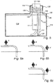
- the reference part 28 of the measurement device is shaped like a flat spiral and positioned outside of the tank.
- the measurement device further comprises a container 50, in which the flat spiral shaped reference part is placed.
- the container 50 has an essentially circular base plate 52 and a wall 54 extending up from the edge of the base plate.
- the container 50 is connected to the tank through an opening 56 at the base plate 52, whereby the waveguide 12 passes the opening 56 in to the tank.
- the container 50 further comprises an absorbing layer 58 extending over the base plate 52 of the container, and down into the opening 56 to the tank. Note that the lower ends 60 of the absorbing layer 58 are positioned in the passage to the tank.
- the absorbing layer 58 may for example be an absorbing cloth, such as a sponge cloth.
- excess fluid which originates from for example a flow through the reference part 28 and/or condensation, emanates from the drainage holes 42 and is absorbed by the absorbing cloth 58. Since the ends 60 of the absorbing cloth 58 are positioned at a lower level than the part of the absorbing cloth at the base plate 52 of the container 50, the fluid will accumulate in the ends 60, and drip off back into the tank 18 because of the siphon principle. Also, by elevating the container 50 off the top surface of the tank 18 a distance C, it is possible to use the siphon function, and thus the measurement device, even if the whole tank tilts, as long as the distance denoted D in fig. 3 is larger than zero. Thus, when designing the measurement device, the elevation of the container 50 may be chosen so that the tank measurement device can manage measurements up to a desired tilt angle of the tank.
- devices for acoustically measuring the level of a fluid in a tank are known in the prior art.
- One such device is disclosed in UK patent application GB2 164 151 , which discloses an acoustic liquid level measuring apparatus for determining the level of liquid in a tank.
- the apparatus comprises a tube, whereby one end of the tube is immersed in the liquid, and the other end is arranged with a transducer.
- the tube is also arranged with two reference means situated along the tube between the two ends of the tube.
- the transducer produces source pulses which are partially reflected by the reference means, and the remaining pulse energy is reflected by the liquid surface, whereby the time delays between the echoes may be used to calculate the liquid level in the tank.
- plane wave propagation When measuring with acoustic signals in a waveguide, it is advantageous to use plane wave propagation, which for example makes it possible to reduce disturbances.
- One condition for plane wave propagation of an acoustic signal in a waveguide is that the wavelength of the signal has to be much larger than the diameter of the waveguide.
- the waveguide In order to enable separation of the reflected signals, the waveguide must be several wavelengths long. Therefore, as a waveguide typically has a diameter in the order one centimetre, the waveguide in a measuring apparatus employing plane wave propagation must be very long, ranging from several decimetres up about one meter.
- Figs. 4 and 5 show a fluid level measurement device according to two embodiments of the invention. Identical reference numerals have been used for the same structures in both figures.
- the measurement device is arranged to be associated with a container or tank.
- the tank may for example be a fuel tank of a boat or a vehicle, such as a car or a truck.
- the fluid which is to be measured may for example be a liquid such as petrol, diesel or water or the like.
- the tank shown in fig. 4 and fig 5 also contains a fuel pump 11.
- the measurement device 110 comprises a waveguide 112 having one end which is connected to a transducer 114, while the other end extends into the fluid 116 which is contained in the tank 118.
- the end 120 of the waveguide 112 extending into the fluid 116 has an opening to allow fluid to enter the waveguide.
- the end 120 of the waveguide extending into the fluid is preferably partially fixed to the bottom part of the tank 118. This ensures the position of the end 120 of the waveguide 112, and enables fluid level measurement from the very bottom of the tank.
- the waveguide in fig. 4 extends essentially straight down through the tank from the transducer. However, it is possible to place the measurement point, i.e. the end 120 of the waveguide, anywhere in the tank. For example the measurement point may be positioned at the centre of the bottom of the tank, even though the transducer may be positioned in for example a top corner of the tank.
- the abovementioned transducer 114 may for example be a low-cost piezoelectric component, or a separate sound transmitter and sound receiver.
- the transducer is arranged in connection with an electronic control device 122, which is arranged to control the transducer and to calculate the fluid level based on the signals transmitted and received by the transducer.
- the waveguide 112 comprises a reference element 126, for example a protrusion disposed within the waveguide.
- the reference element 126 may for example be annularly shaped, or comprise a pin arranged in the wall of the waveguide.
- the part of the waveguide 112 extending from the end connected with the transducer 114 to the reference element 126 is hereinafter referred to as the reference part 128 of the waveguide.
- the part of the waveguide 112 from the bottom of the tank 120 to the maximum tank height 130, i.e. the highest possible fluid level, is hereinafter referred to as the measurement part 132 of the waveguide 112.
- the part of the waveguide 112 between the reference and measurement part is referred to as the "dead" part 134.
- the transducer 114 When measuring the fluid level, the transducer 114 is fed with an electric signal from the control device 122 in order to produce an sound pulse.
- the sound pulse A is transmitted from the transducer 114 and guided through the waveguide 112 towards the fluid surface 136.
- the sound pulse A is partially reflected by the reference element 126, and a reflected pulse B returns toward the transducer.
- the remainder of the pulse A' passes the dead part 134 and travels through the measurement part 132 until it is reflected by the surface 136 of the fluid.
- two reflected pulses B and C return to the transducer 114.
- One reflected pulse B is associated with the reference element, and the other reflected pulse C is associated with the surface of the fluid.
- the transducer 114 As a response to the received sound pulses, the transducer 114 generates corresponding electric signals and feeds it back to the control device 122.
- the dead part 134 is long enough to ensure that the two pulses B and C are sufficiently separated so that the two pulses are distinguishable, even if the tank is filled to the top and thus the pulses B and C are returning to the transducer in relatively close proximity.
- the fluid level is calculated by reducing the total length of the waveguide with the length of the waveguide above the surface.
- the speed of sound generally varies in regard of temperature and gas composition.
- the overall measurement is relatively insensitive regarding temperature and gas composition.
- the measurement part 132 is essentially vertical and an absolute measure of the fluid level is obtained.
- it is also possible to tilt the measurement part in order to make it fit into different tanks with different heights. In that case it is advantageous to calculate the relationship between the fluid level and the maximum level of the tank in order to avoid further calibration, whereby: Relationship level / measurement part
- the reference part 128 of the waveguide is curved in a plane essentially parallel to the surface 136 of the fluid.
- the reference part 128 is shaped like a flat spiral. This ensures that the measurement device occupies as less space as possible in connection with the tank.
- the reference part 128 of the waveguide is contained in a bulge 138 in the tank 118, together with the transducer 114, while the electronic control device 122 is placed outside of the tank.
- the reference part of the waveguide may be helically shaped, as shown in fig. 5 .
- the reference part 128 is arranged around the fuel pump 111, and thus utilizing the space around said fuel pump.
- the helical reference part 128 may alternatively be placed in a similar manner to that discussed above regarding the flat spiral shaped reference, i.e. inside the tank independent of the fuel pump, for example in a bulge in the ceiling of the tank, or just outside the tank.
- the wavelength is much larger than the diameter of the waveguide.
- the wavelength should be longer than approximately the double diameter.
- the wavelength of the acoustic pulses is preferably in the interval about 2-10 cm, which corresponds to a frequency of about 3,4-17 kHz, i.e. not ultrasound. Because of the relatively long wavelength, the waveguide also has to be long.
- the length of the reference part is up to about 70 cm, and the length of the dead part is up to about 30 cm.
- the reference part 128 of the waveguide is contained in the tank 118, together with the transducer 114, while the electronic control device 122 is placed outside of the tank.
- the control device may be placed inside of the tank together with the transducer.
- the waveguide 112 in figs. 4 and 5 may also comprise additional reference elements positioned at known distances from the first reference element 126. When using for example one additional reference element, one further sound pulse returns to the transceiver, whereby the transit time of the pulse is used to calculate the current speed of sound. Additional reference elements may for example be positioned in the measurement part, or between the transducer and the first reference element. The former results in that the reference part is closer to the fluid when the fluid level is low.
- Figs. 7-9 show embodiments of the second aspect of the present invention, wherein the fluid level may be measured at two different positions in the tank.
- the measurement devices in figs. 7-9 have the same basic structure and features as the devices shown in figs. 4 and 5 , and identical reference numerals have been used for the same structures in all figures.
- Fig. 7 shows a measurement device 110 similar to that in fig. 5 , further comprising a second waveguide 140, which is connected to the end of the dead part 134 and extends into the fluid 116.
- the end 142 of the second waveguide extending into the fluid has an opening to allow fluid to enter the waveguide 140.
- the end 142 is preferably placed at different position compared to the end 120 of the first waveguide 112, and partially fixed to the bottom part of the tank 118 to ensure the position of the end of the waveguide.
- the tank 118 in fig. 7 is a so-called saddle-tank, which comprises an indentation 144 at the bottom of the tank, whereby one waveguide 112, 140 is arranged on each side of the indentation 144.
- the measurement device is built around only a single reference part 128 and a single transducer 114 and control device 122, which enables a more cost-efficient realisation of the device, as well as enables that only one opening of the tank 118 is required for the measurement device, even though the device features two separate measurement points.
- a sound pulse is transmitted from the transducer 114, just like was described above. After being partially reflected by the reference element 126 and having passed the dead part 134, the pulse is split up and travels through the measurement part 132 and the second waveguide 140 respectively, and is reflected by the fluid surface 136 in each guide 132, 140. Thus, three reflected pulses return to the transducer 114.
- One reflected pulse is associated with the reference element 126, one is associated with the surface of the fluid at the measurement part 132, and one is associated with the surface of the fluid at the second waveguide 140.
- the measurement part 132 and the second waveguide 140 needs to be of different lengths so that it is possible to distinguish the two echoes from each other.
- the electronic control device 122 By knowing the time spent for each pulse, and the distance of the reference part, the dead part and the waveguides extending into the fluid, it is possible to calculate the fluid level or fluid volume in the tank. The calculation is made by the electronic control device 122.
- the second waveguide 140 may be connected to the transducer 114, which is shown in figs. 8a and 8b .
- the second waveguide 140 comprises a reference part 148, a dead part 150 and measurement part 152 similar to the first waveguide 112.
- the second waveguide 140 may be positioned on either the same side of the transducer 114 as the first waveguide 112 ( fig 8a ), or on the opposite side of the transducer 114 ( fig 8b ).
- the transducer 114 is arranged to transmit the pulses in both directions.
- a sound pulse is transmitted from the transducer 114 and guided through the waveguides 112, 140 towards the fluid surface 136.
- the sound pulse is partially reflected by the reference elements 126, 154 at the end of each reference part of the waveguides.
- the reference parts 128, 148 are so arranged that the echoes relating to the reference elements returning to the transducer 114 may be separated.
- the remainder of the pulse passes the dead parts 134, 150 and travels through the measurement part 132, 152 of the first and second waveguide respectively, and is reflected by the surface of the fluid.
- reflected pulses return to the transducer 112.
- One reflected pulse is associated with the reference element 126 of the first waveguide, one is associated with the reference element 154 of the second waveguide, one is associated with the surface of the fluid at the measurement part 132 of the first waveguide, and one is associated with the surface of the fluid at the measurement part 152 of the second waveguide.
- the measurement parts of the first and second waveguide need to be of different lengths so that it is possible to distinguish the two echoes from each other.
- the second waveguide 140 may be connected to a second transducer 156 as shown in fig. 9 .
- the second waveguide 140 and the second transducer 156 have the same structure and operation as the first waveguide 112 and the first transducer 114 in fig. 4 .
- the measurement parts are placed at different positions in the tank to allow a more accurate reading of the fluid level.
- the transducers can preferably be arranged in the same region of the tank, and are connected to a single electronic control device 122, which calculates the overall fluid level based on the individual readings of the first and second transducers 114, 156 and waveguides 112, 140.
- the use of two measurement points also makes it possible to provide a level measurement which is independent of the tilting of the tank.
- one waveguide is placed at each side of the tank, whereby the time difference of the reception of the echo pulses is calculated in order to provide a tilt compensated liquid level measurement.
- the aspect of drainage holes may be combined with any measurement device where excess fluid needs to be drained out of the waveguide.
- additional measurement waveguides may be connected to the measurement device, which enables measurements from different parts of a tank.
- a common transducer and reference part may be used.
- the absorbing cloth may be used in combination with any structure, such as the funnel discussed above.
- the reference parts 28, 48 of the measurement devices in figs. 7-9 are helical and arranged around the fuel pump 11 of the tank 18.
- the reference part may alternatively be placed at a position independent of the fuel pump, either inside or outside of the tank.
- the reference part may also have a flat spiral shape as in fig. 4 .
- the aspect of several waveguides may be combined with any conventional device.
- the waveguides extending into the fluid may be conically shaped so that the diameter at the bottom of end of the waveguide is larger than the diameter at the top part of the waveguide. This enables a better relief angle.
- the waveguides may in whole or partly have a cross sectional design that is round, rectangular or flat or the like.
Claims (8)
- Dispositif pour mesurer le niveau d'un fluide (116) dans un réservoir (118) en utilisant des impulsions acoustiques de basse fréquence, ledit dispositif comprenant :- un moyen transducteur (114) pour la transmission et la réception d'impulsions acoustiques, et- un guide d'ondes (112) relié audit transducteur (114) et disposé de manière à s'étendre à l'intérieur du fluide (116),lesdites impulsions acoustiques ayant une longueur d'onde qui est plus longue que le double du diamètre du guide d'ondes afin de garantir une propagation d'onde plane,
ledit guide d'ondes ayant un organe de référence (128) disposé de manière à se situer au-dessus de la surface du fluide et s'étendant entre le transducteur et un élément de référence (26), ledit élément de référence (26) étant disposé de manière à partiellement refléter une impulsion acoustique du transducteur pour permettre la détermination de la vitesse actuelle du son,
caractérisé en ce que
ledit organe de référence (128) du guide d'ondes est hélicoïdal ou a la forme d'une spirale plate. - Dispositif selon la revendication 1, dans lequel ledit organe de référence (128) du guide d'ondes est doté d'une pluralité de courbures dans un plan sensiblement parallèle à la surface du fluide.
- Dispositif selon la revendication 1 ou 2, dans lequel ledit organe de référence (128) du guide d'ondes est doté d'une pluralité de torsions à 360° dans un plan sensiblement parallèle à la surface du fluide.
- Dispositif selon l'une quelconque des revendications 1 - 3, comprenant par ailleurs un deuxième guide d'ondes (140) s'étendant à l'intérieur du fluide (116).
- Dispositif selon la revendication 4, dans lequel ledit guide d'ondes (112) et ledit deuxième guide d'ondes (140) sont reliés audit transducteur (114) respectivement sur des côtés opposés dudit transducteur.
- Dispositif selon la revendication 4, dans lequel ledit guide d'ondes (112) et ledit deuxième guide d'ondes (140) ont un organe de référence (128) commun.
- Dispositif selon la revendication 4, comprenant par ailleurs un deuxième transducteur (156), dans lequel ledit deuxième guide d'ondes (140) est relié audit deuxième transducteur.
- Système de mesure de niveau étudié pour mesurer le niveau du contenu dans un réservoir, comprenant un dispositif selon l'une quelconque des revendications 4 - 7, et un dispositif de commande électronique (122) disposé de manière à se situer à l'extérieur du réservoir, dans lequel le(s) transducteur(s) est/sont disposé(s) de manière à se situer à l'intérieur du réservoir.
Applications Claiming Priority (3)
| Application Number | Priority Date | Filing Date | Title |
|---|---|---|---|
| SE0302709A SE527128C2 (sv) | 2003-10-15 | 2003-10-15 | Anordning för mätning av vätskenivå |
| SE0302710A SE0302710D0 (sv) | 2003-10-15 | 2003-10-15 | Fluid level measurement device |
| EP04775555A EP1676102B1 (fr) | 2003-10-15 | 2004-10-15 | Dispositif de mesure du niveau des liquides |
Related Parent Applications (1)
| Application Number | Title | Priority Date | Filing Date |
|---|---|---|---|
| EP04775555A Division EP1676102B1 (fr) | 2003-10-15 | 2004-10-15 | Dispositif de mesure du niveau des liquides |
Publications (3)
| Publication Number | Publication Date |
|---|---|
| EP1962066A2 EP1962066A2 (fr) | 2008-08-27 |
| EP1962066A3 EP1962066A3 (fr) | 2008-09-03 |
| EP1962066B1 true EP1962066B1 (fr) | 2016-02-24 |
Family
ID=34467905
Family Applications (2)
| Application Number | Title | Priority Date | Filing Date |
|---|---|---|---|
| EP04775555A Active EP1676102B1 (fr) | 2003-10-15 | 2004-10-15 | Dispositif de mesure du niveau des liquides |
| EP08158367.6A Active EP1962066B1 (fr) | 2003-10-15 | 2004-10-15 | Dispositif de mesure de niveau d'un fluide |
Family Applications Before (1)
| Application Number | Title | Priority Date | Filing Date |
|---|---|---|---|
| EP04775555A Active EP1676102B1 (fr) | 2003-10-15 | 2004-10-15 | Dispositif de mesure du niveau des liquides |
Country Status (9)
| Country | Link |
|---|---|
| US (2) | US7571645B2 (fr) |
| EP (2) | EP1676102B1 (fr) |
| JP (1) | JP4689617B2 (fr) |
| KR (1) | KR101169103B1 (fr) |
| AT (1) | ATE399309T1 (fr) |
| DE (1) | DE602004014631D1 (fr) |
| ES (2) | ES2308244T3 (fr) |
| PL (1) | PL1676102T3 (fr) |
| WO (1) | WO2005038415A1 (fr) |
Families Citing this family (29)
| Publication number | Priority date | Publication date | Assignee | Title |
|---|---|---|---|---|
| ATE399309T1 (de) * | 2003-10-15 | 2008-07-15 | Axsensor Ab | Messeinrichtung für fluidpegel |
| EP1748285A1 (fr) * | 2005-07-29 | 2007-01-31 | Truma Gerätetechnik GmbH & Co. KG | Dispositif de mesure de niveau à ultrasons avec reconnaissance de niveau de seuil |
| SE529551C2 (sv) * | 2006-07-12 | 2007-09-11 | Axsensor Ab | Vätskenivåmätanordning |
| JP2010533294A (ja) * | 2006-07-12 | 2010-10-21 | アクセンサー エービー | 液位測定装置 |
| US8746045B2 (en) | 2006-11-17 | 2014-06-10 | Meggitt (Orange County), Inc. | System and method for identifying fluids and monitoring fluid quality in a vessel |
| US7650785B1 (en) * | 2006-11-17 | 2010-01-26 | Vibro-Meter, Inc. | Scan lock and track fluid characterization and level sensor apparatus and method |
| US8794063B2 (en) * | 2007-01-08 | 2014-08-05 | Meggitt (Orange County), Inc. | System and method for optimizing sweep delay and aliasing for time domain reflectometric measurement of liquid height within a tank |
| KR101496668B1 (ko) | 2007-06-01 | 2015-02-27 | 악센소르 아베 | 변환기 장치 및 이를 조립하는 방법 |
| EP2183552B1 (fr) | 2007-08-07 | 2013-08-28 | Axsensor AB | Dispositif et procédé de mesure de niveau de liquide |
| RU2482453C2 (ru) * | 2007-10-01 | 2013-05-20 | Меджитт (Нью Гэмпшир), Инк., | Система и способ для точного измерения уровня текучей среды в сосуде |
| US8549909B2 (en) | 2007-10-01 | 2013-10-08 | Meggitt (Orange County), Inc. | Vessel probe connector with solid dielectric therein |
| US20110132084A1 (en) * | 2008-08-07 | 2011-06-09 | Illinois Tool Works Inc | Liquid level sensing system |
| US20110091330A1 (en) * | 2009-10-21 | 2011-04-21 | Deoliviera Marcelo | Condensate Removal Pump Controller Using Acoustic Liquid Level Sensor |
| US8258678B2 (en) * | 2010-02-23 | 2012-09-04 | Avago Technologies Wireless Ip (Singapore) Pte. Ltd. | Short range ultrasonic device with broadbeam ultrasonic transducers |
| US9086354B2 (en) | 2010-07-22 | 2015-07-21 | Saudi Arabian Oil Company | Sound-velocity dewatering system |
| WO2012113776A1 (fr) * | 2011-02-23 | 2012-08-30 | Gaslock Gmbh | Dispositif de mesure du niveau de liquides |
| DE102012005281A1 (de) | 2012-03-16 | 2013-09-19 | Emitec France S.A.S | Fördereinheit mit Füllstandsensor für ein flüssiges Additiv |
| DE102012211848B4 (de) * | 2012-07-06 | 2019-08-01 | KSB SE & Co. KGaA | Füllstandmessung |
| US9057638B2 (en) | 2012-11-09 | 2015-06-16 | Robert H. Cameron | System and method for determining the level of a substance in a container based on measurement of resonance from an acoustic circuit that includes unfilled space within the container that changes size as substance is added or removed from the container |
| US9322697B2 (en) | 2012-11-09 | 2016-04-26 | Robert H. Cameron | System and method for determining the level of a substance in a container based on measurement of resonance from an acoustic circuit that includes unfilled space within the container that changes size as substance is added or removed from the container |
| US10184821B2 (en) | 2012-11-09 | 2019-01-22 | Robert H. Cameron | System and method for determining the level of a substance in a container based on measurement of resonance from an acoustic circuit that includes unfilled space within the container that changes size as substance is added or removed from the container |
| US9354101B2 (en) * | 2013-07-11 | 2016-05-31 | Axsensor Ab | Device for providing a gas composition and temperature compensated acoustic measurement of a liquid level |
| US9945737B2 (en) * | 2014-03-13 | 2018-04-17 | Siemens Energy, Inc. | Method for determining waveguide temperature for acoustic transceiver used in a gas turbine engine |
| JP6282514B2 (ja) * | 2014-04-04 | 2018-02-21 | 愛三工業株式会社 | 液量検出装置 |
| DE102014109843A1 (de) * | 2014-07-14 | 2016-01-14 | Continental Automotive Gmbh | Verfahren zur Bestimmung des Füllstands in einem Tank |
| CN107923785B (zh) * | 2015-07-09 | 2020-01-31 | 艾克森赛股份公司 | 提供液体液位的气体组分和温度补偿声学测量的装置 |
| US10578479B2 (en) * | 2017-08-09 | 2020-03-03 | Fluke Corporation | Calibration bath with acoustic liquid level sensor |
| KR102302252B1 (ko) * | 2020-04-24 | 2021-09-14 | 숭실대학교산학협력단 | 초음파 센서용 파동유도관 |
| US11714176B1 (en) * | 2022-09-23 | 2023-08-01 | Texzec, Inc. | Helical acoustic liquid level sensor |
Citations (1)
| Publication number | Priority date | Publication date | Assignee | Title |
|---|---|---|---|---|
| US4933915A (en) * | 1986-09-16 | 1990-06-12 | Bostroem Jan I | Method of indicating the time of an acoustic pulse and a device for carrying out the method |
Family Cites Families (16)
| Publication number | Priority date | Publication date | Assignee | Title |
|---|---|---|---|---|
| US3222929A (en) * | 1964-09-21 | 1965-12-14 | Henry P Kalmus | Augmented-signal mechanical wave depth gauge |
| US4090407A (en) * | 1977-09-19 | 1978-05-23 | T. W. Salisbury, III | Water level measurement device |
| JPS5890129A (ja) * | 1981-11-26 | 1983-05-28 | Nippon Kokan Kk <Nkk> | 超音波式レベル計 |
| GB2164151B (en) | 1984-09-07 | 1988-12-21 | James Gerald Lacy | Measuring apparatus |
| US4909080A (en) * | 1987-10-31 | 1990-03-20 | Toyoda Gosei Co., Ltd. | Ultrasonic level gauge |
| US5062595A (en) * | 1990-04-26 | 1991-11-05 | University Of Southern California | Delta wing with lift enhancing flap |
| WO1991019171A1 (fr) * | 1990-06-05 | 1991-12-12 | Australian Coal Industry Research Laboratories Limited | Systeme et appareil de detection de niveau de fluide |
| US5062295A (en) * | 1990-12-24 | 1991-11-05 | Sparktech | Dual tube sonic level gage |
| US5319973A (en) * | 1993-02-02 | 1994-06-14 | Caterpillar Inc. | Ultrasonic fuel level sensing device |
| US5471872A (en) * | 1994-01-07 | 1995-12-05 | Semitool, Inc. | Acoustic liquid level measuring apparatus |
| GB9800533D0 (en) * | 1998-01-13 | 1998-03-11 | Saw Technologies Ltd | Method and apparatus for detecting an interface |
| US6360599B1 (en) * | 1999-08-25 | 2002-03-26 | National Institute Of Ocean Technology Department Of Ocean Development Govenment Of India | Device for measuring liquid level preferably measuring tide level in sea |
| JP2001082262A (ja) * | 1999-09-13 | 2001-03-27 | Denso Corp | 圧電センサユニット |
| RU2193164C1 (ru) * | 2001-10-05 | 2002-11-20 | Балин Николай Иванович | Устройство для измерения уровня жидкости (варианты) |
| DE10312101A1 (de) * | 2003-03-19 | 2004-09-30 | Robert Bosch Gmbh | Vorrichtung zur Messung eines Füllstandes einer Flüssigkeit in einem Behälter |
| ATE399309T1 (de) * | 2003-10-15 | 2008-07-15 | Axsensor Ab | Messeinrichtung für fluidpegel |
-
2004
- 2004-10-15 AT AT04775555T patent/ATE399309T1/de not_active IP Right Cessation
- 2004-10-15 DE DE602004014631T patent/DE602004014631D1/de active Active
- 2004-10-15 EP EP04775555A patent/EP1676102B1/fr active Active
- 2004-10-15 KR KR1020067009438A patent/KR101169103B1/ko active IP Right Grant
- 2004-10-15 EP EP08158367.6A patent/EP1962066B1/fr active Active
- 2004-10-15 ES ES04775555T patent/ES2308244T3/es active Active
- 2004-10-15 ES ES08158367.6T patent/ES2569212T3/es active Active
- 2004-10-15 PL PL04775555T patent/PL1676102T3/pl unknown
- 2004-10-15 JP JP2006535312A patent/JP4689617B2/ja not_active Expired - Fee Related
- 2004-10-15 WO PCT/SE2004/001483 patent/WO2005038415A1/fr active Application Filing
- 2004-10-15 US US10/575,896 patent/US7571645B2/en active Active
-
2009
- 2009-05-07 US US12/453,327 patent/US7856876B2/en active Active
Patent Citations (1)
| Publication number | Priority date | Publication date | Assignee | Title |
|---|---|---|---|---|
| US4933915A (en) * | 1986-09-16 | 1990-06-12 | Bostroem Jan I | Method of indicating the time of an acoustic pulse and a device for carrying out the method |
Also Published As
| Publication number | Publication date |
|---|---|
| US7856876B2 (en) | 2010-12-28 |
| EP1676102B1 (fr) | 2008-06-25 |
| KR101169103B1 (ko) | 2012-07-26 |
| ES2308244T3 (es) | 2008-12-01 |
| EP1962066A3 (fr) | 2008-09-03 |
| ES2569212T3 (es) | 2016-05-09 |
| WO2005038415A1 (fr) | 2005-04-28 |
| EP1962066A2 (fr) | 2008-08-27 |
| EP1676102A1 (fr) | 2006-07-05 |
| KR20060098386A (ko) | 2006-09-18 |
| ATE399309T1 (de) | 2008-07-15 |
| US20090282911A1 (en) | 2009-11-19 |
| US7571645B2 (en) | 2009-08-11 |
| DE602004014631D1 (de) | 2008-08-07 |
| JP4689617B2 (ja) | 2011-05-25 |
| US20070204689A1 (en) | 2007-09-06 |
| JP2007510140A (ja) | 2007-04-19 |
| PL1676102T3 (pl) | 2008-12-31 |
Similar Documents
| Publication | Publication Date | Title |
|---|---|---|
| EP1962066B1 (fr) | Dispositif de mesure de niveau d'un fluide | |
| US5119676A (en) | Ultrasonic method and apparatus for determining water level in a closed vessel | |
| CA1123946A (fr) | Transducteur ultrasonore avec reflecteur de reference | |
| US5309763A (en) | Liquid-level gauging | |
| US20100018309A1 (en) | Fluid level measuring method and system therefor | |
| US7542870B2 (en) | Immersed fuel level sensor | |
| CN103674180B (zh) | 具有气泡脱落反射器的液位测量系统 | |
| US5357801A (en) | Liquid-level gauging | |
| CA2048344A1 (fr) | Systeme de controle du volume de liquide contenu dans un reservoir de stockage | |
| US8919193B2 (en) | Ultrasonic liquid level detector | |
| US6202484B1 (en) | Method and device for determining a liquid level with the aid of ultrasonic pulses | |
| JP2003121241A (ja) | 流体計測方法 | |
| EP2041528B1 (fr) | Dispositif de mesure du niveau d'un liquide | |
| US9880044B2 (en) | Acoustic array sensor | |
| WO2006134358A1 (fr) | Sonde a onde acoustique pour capter un niveau de fluide | |
| CN100442028C (zh) | 流体位测量设备和方法 | |
| JPH09229748A (ja) | 超音波液面レベルセンサ | |
| GB2311373A (en) | Fluid-gauging systems and probes | |
| CN101458113B (zh) | 流体位测量设备 | |
| RU30974U1 (ru) | Ультразвуковое устройство для измерения уровня жидкости в резервуарах | |
| JPS609698Y2 (ja) | 液面レベル計 | |
| JPH08327437A (ja) | 液面追随型界面レベル計 |
Legal Events
| Date | Code | Title | Description |
|---|---|---|---|
| PUAI | Public reference made under article 153(3) epc to a published international application that has entered the european phase |
Free format text: ORIGINAL CODE: 0009012 |
|
| PUAL | Search report despatched |
Free format text: ORIGINAL CODE: 0009013 |
|
| AC | Divisional application: reference to earlier application |
Ref document number: 1676102 Country of ref document: EP Kind code of ref document: P |
|
| AK | Designated contracting states |
Kind code of ref document: A2 Designated state(s): AT BE BG CH CY CZ DE DK EE ES FI FR GB GR HU IE IT LI LU MC NL PL PT RO SE SI SK TR |
|
| AK | Designated contracting states |
Kind code of ref document: A3 Designated state(s): AT BE BG CH CY CZ DE DK EE ES FI FR GB GR HU IE IT LI LU MC NL PL PT RO SE SI SK TR |
|
| 17P | Request for examination filed |
Effective date: 20090225 |
|
| AKX | Designation fees paid |
Designated state(s): AT BE BG CH CY CZ DE DK EE ES FI FR GB GR HU IE IT LI LU MC NL PL PT RO SE SI SK TR |
|
| 17Q | First examination report despatched |
Effective date: 20090731 |
|
| APBK | Appeal reference recorded |
Free format text: ORIGINAL CODE: EPIDOSNREFNE |
|
| APBN | Date of receipt of notice of appeal recorded |
Free format text: ORIGINAL CODE: EPIDOSNNOA2E |
|
| APAZ | Date of receipt of statement of grounds of appeal deleted |
Free format text: ORIGINAL CODE: EPIDOSDNOA3E |
|
| APBR | Date of receipt of statement of grounds of appeal recorded |
Free format text: ORIGINAL CODE: EPIDOSNNOA3E |
|
| APAV | Appeal reference deleted |
Free format text: ORIGINAL CODE: EPIDOSDREFNE |
|
| APBX | Invitation to file observations in appeal sent |
Free format text: ORIGINAL CODE: EPIDOSNOBA2E |
|
| APBZ | Receipt of observations in appeal recorded |
Free format text: ORIGINAL CODE: EPIDOSNOBA4E |
|
| APBT | Appeal procedure closed |
Free format text: ORIGINAL CODE: EPIDOSNNOA9E |
|
| GRAP | Despatch of communication of intention to grant a patent |
Free format text: ORIGINAL CODE: EPIDOSNIGR1 |
|
| INTG | Intention to grant announced |
Effective date: 20150908 |
|
| RIN1 | Information on inventor provided before grant (corrected) |
Inventor name: BOSTROEM, JAN |
|
| GRAS | Grant fee paid |
Free format text: ORIGINAL CODE: EPIDOSNIGR3 |
|
| GRAA | (expected) grant |
Free format text: ORIGINAL CODE: 0009210 |
|
| AC | Divisional application: reference to earlier application |
Ref document number: 1676102 Country of ref document: EP Kind code of ref document: P |
|
| AK | Designated contracting states |
Kind code of ref document: B1 Designated state(s): AT BE BG CH CY CZ DE DK EE ES FI FR GB GR HU IE IT LI LU MC NL PL PT RO SE SI SK TR |
|
| REG | Reference to a national code |
Ref country code: GB Ref legal event code: FG4D |
|
| REG | Reference to a national code |
Ref country code: CH Ref legal event code: EP |
|
| REG | Reference to a national code |
Ref country code: AT Ref legal event code: REF Ref document number: 776960 Country of ref document: AT Kind code of ref document: T Effective date: 20160315 |
|
| REG | Reference to a national code |
Ref country code: IE Ref legal event code: FG4D |
|
| REG | Reference to a national code |
Ref country code: DE Ref legal event code: R096 Ref document number: 602004048697 Country of ref document: DE |
|
| REG | Reference to a national code |
Ref country code: ES Ref legal event code: FG2A Ref document number: 2569212 Country of ref document: ES Kind code of ref document: T3 Effective date: 20160509 |
|
| REG | Reference to a national code |
Ref country code: SE Ref legal event code: TRGR |
|
| REG | Reference to a national code |
Ref country code: NL Ref legal event code: MP Effective date: 20160224 |
|
| REG | Reference to a national code |
Ref country code: AT Ref legal event code: MK05 Ref document number: 776960 Country of ref document: AT Kind code of ref document: T Effective date: 20160224 |
|
| PG25 | Lapsed in a contracting state [announced via postgrant information from national office to epo] |
Ref country code: GR Free format text: LAPSE BECAUSE OF FAILURE TO SUBMIT A TRANSLATION OF THE DESCRIPTION OR TO PAY THE FEE WITHIN THE PRESCRIBED TIME-LIMIT Effective date: 20160525 Ref country code: FI Free format text: LAPSE BECAUSE OF FAILURE TO SUBMIT A TRANSLATION OF THE DESCRIPTION OR TO PAY THE FEE WITHIN THE PRESCRIBED TIME-LIMIT Effective date: 20160224 |
|
| PG25 | Lapsed in a contracting state [announced via postgrant information from national office to epo] |
Ref country code: PL Free format text: LAPSE BECAUSE OF FAILURE TO SUBMIT A TRANSLATION OF THE DESCRIPTION OR TO PAY THE FEE WITHIN THE PRESCRIBED TIME-LIMIT Effective date: 20160224 Ref country code: PT Free format text: LAPSE BECAUSE OF FAILURE TO SUBMIT A TRANSLATION OF THE DESCRIPTION OR TO PAY THE FEE WITHIN THE PRESCRIBED TIME-LIMIT Effective date: 20160624 Ref country code: AT Free format text: LAPSE BECAUSE OF FAILURE TO SUBMIT A TRANSLATION OF THE DESCRIPTION OR TO PAY THE FEE WITHIN THE PRESCRIBED TIME-LIMIT Effective date: 20160224 Ref country code: NL Free format text: LAPSE BECAUSE OF FAILURE TO SUBMIT A TRANSLATION OF THE DESCRIPTION OR TO PAY THE FEE WITHIN THE PRESCRIBED TIME-LIMIT Effective date: 20160224 |
|
| REG | Reference to a national code |
Ref country code: FR Ref legal event code: PLFP Year of fee payment: 13 |
|
| PG25 | Lapsed in a contracting state [announced via postgrant information from national office to epo] |
Ref country code: DK Free format text: LAPSE BECAUSE OF FAILURE TO SUBMIT A TRANSLATION OF THE DESCRIPTION OR TO PAY THE FEE WITHIN THE PRESCRIBED TIME-LIMIT Effective date: 20160224 Ref country code: EE Free format text: LAPSE BECAUSE OF FAILURE TO SUBMIT A TRANSLATION OF THE DESCRIPTION OR TO PAY THE FEE WITHIN THE PRESCRIBED TIME-LIMIT Effective date: 20160224 |
|
| REG | Reference to a national code |
Ref country code: DE Ref legal event code: R097 Ref document number: 602004048697 Country of ref document: DE |
|
| PG25 | Lapsed in a contracting state [announced via postgrant information from national office to epo] |
Ref country code: CZ Free format text: LAPSE BECAUSE OF FAILURE TO SUBMIT A TRANSLATION OF THE DESCRIPTION OR TO PAY THE FEE WITHIN THE PRESCRIBED TIME-LIMIT Effective date: 20160224 Ref country code: SK Free format text: LAPSE BECAUSE OF FAILURE TO SUBMIT A TRANSLATION OF THE DESCRIPTION OR TO PAY THE FEE WITHIN THE PRESCRIBED TIME-LIMIT Effective date: 20160224 Ref country code: RO Free format text: LAPSE BECAUSE OF FAILURE TO SUBMIT A TRANSLATION OF THE DESCRIPTION OR TO PAY THE FEE WITHIN THE PRESCRIBED TIME-LIMIT Effective date: 20160224 |
|
| PG25 | Lapsed in a contracting state [announced via postgrant information from national office to epo] |
Ref country code: BE Free format text: LAPSE BECAUSE OF FAILURE TO SUBMIT A TRANSLATION OF THE DESCRIPTION OR TO PAY THE FEE WITHIN THE PRESCRIBED TIME-LIMIT Effective date: 20160224 |
|
| PLBE | No opposition filed within time limit |
Free format text: ORIGINAL CODE: 0009261 |
|
| STAA | Information on the status of an ep patent application or granted ep patent |
Free format text: STATUS: NO OPPOSITION FILED WITHIN TIME LIMIT |
|
| 26N | No opposition filed |
Effective date: 20161125 |
|
| PG25 | Lapsed in a contracting state [announced via postgrant information from national office to epo] |
Ref country code: BG Free format text: LAPSE BECAUSE OF FAILURE TO SUBMIT A TRANSLATION OF THE DESCRIPTION OR TO PAY THE FEE WITHIN THE PRESCRIBED TIME-LIMIT Effective date: 20160524 Ref country code: SI Free format text: LAPSE BECAUSE OF FAILURE TO SUBMIT A TRANSLATION OF THE DESCRIPTION OR TO PAY THE FEE WITHIN THE PRESCRIBED TIME-LIMIT Effective date: 20160224 |
|
| REG | Reference to a national code |
Ref country code: CH Ref legal event code: PL |
|
| REG | Reference to a national code |
Ref country code: IE Ref legal event code: MM4A |
|
| PG25 | Lapsed in a contracting state [announced via postgrant information from national office to epo] |
Ref country code: LI Free format text: LAPSE BECAUSE OF NON-PAYMENT OF DUE FEES Effective date: 20161031 Ref country code: CH Free format text: LAPSE BECAUSE OF NON-PAYMENT OF DUE FEES Effective date: 20161031 |
|
| PG25 | Lapsed in a contracting state [announced via postgrant information from national office to epo] |
Ref country code: LU Free format text: LAPSE BECAUSE OF NON-PAYMENT OF DUE FEES Effective date: 20161015 |
|
| REG | Reference to a national code |
Ref country code: FR Ref legal event code: PLFP Year of fee payment: 14 |
|
| PG25 | Lapsed in a contracting state [announced via postgrant information from national office to epo] |
Ref country code: IE Free format text: LAPSE BECAUSE OF NON-PAYMENT OF DUE FEES Effective date: 20161015 |
|
| PG25 | Lapsed in a contracting state [announced via postgrant information from national office to epo] |
Ref country code: HU Free format text: LAPSE BECAUSE OF FAILURE TO SUBMIT A TRANSLATION OF THE DESCRIPTION OR TO PAY THE FEE WITHIN THE PRESCRIBED TIME-LIMIT; INVALID AB INITIO Effective date: 20041015 Ref country code: CY Free format text: LAPSE BECAUSE OF FAILURE TO SUBMIT A TRANSLATION OF THE DESCRIPTION OR TO PAY THE FEE WITHIN THE PRESCRIBED TIME-LIMIT Effective date: 20160224 |
|
| PG25 | Lapsed in a contracting state [announced via postgrant information from national office to epo] |
Ref country code: MC Free format text: LAPSE BECAUSE OF FAILURE TO SUBMIT A TRANSLATION OF THE DESCRIPTION OR TO PAY THE FEE WITHIN THE PRESCRIBED TIME-LIMIT Effective date: 20160224 Ref country code: TR Free format text: LAPSE BECAUSE OF FAILURE TO SUBMIT A TRANSLATION OF THE DESCRIPTION OR TO PAY THE FEE WITHIN THE PRESCRIBED TIME-LIMIT Effective date: 20160224 |
|
| REG | Reference to a national code |
Ref country code: FR Ref legal event code: PLFP Year of fee payment: 15 |
|
| PGFP | Annual fee paid to national office [announced via postgrant information from national office to epo] |
Ref country code: SE Payment date: 20220914 Year of fee payment: 19 Ref country code: GB Payment date: 20220915 Year of fee payment: 19 |
|
| PGFP | Annual fee paid to national office [announced via postgrant information from national office to epo] |
Ref country code: FR Payment date: 20220916 Year of fee payment: 19 |
|
| PGFP | Annual fee paid to national office [announced via postgrant information from national office to epo] |
Ref country code: IT Payment date: 20220926 Year of fee payment: 19 Ref country code: ES Payment date: 20221102 Year of fee payment: 19 Ref country code: DE Payment date: 20220921 Year of fee payment: 19 |