EP1961919A2 - Aube de rotor variable pour moteur de turbine à gaz - Google Patents
Aube de rotor variable pour moteur de turbine à gaz Download PDFInfo
- Publication number
- EP1961919A2 EP1961919A2 EP08250587A EP08250587A EP1961919A2 EP 1961919 A2 EP1961919 A2 EP 1961919A2 EP 08250587 A EP08250587 A EP 08250587A EP 08250587 A EP08250587 A EP 08250587A EP 1961919 A2 EP1961919 A2 EP 1961919A2
- Authority
- EP
- European Patent Office
- Prior art keywords
- blade
- rotor
- rotation
- downstream
- variable
- Prior art date
- Legal status (The legal status is an assumption and is not a legal conclusion. Google has not performed a legal analysis and makes no representation as to the accuracy of the status listed.)
- Granted
Links
Images


Classifications
-
- F—MECHANICAL ENGINEERING; LIGHTING; HEATING; WEAPONS; BLASTING
- F04—POSITIVE - DISPLACEMENT MACHINES FOR LIQUIDS; PUMPS FOR LIQUIDS OR ELASTIC FLUIDS
- F04D—NON-POSITIVE-DISPLACEMENT PUMPS
- F04D29/00—Details, component parts, or accessories
- F04D29/26—Rotors specially for elastic fluids
- F04D29/32—Rotors specially for elastic fluids for axial flow pumps
- F04D29/34—Blade mountings
- F04D29/36—Blade mountings adjustable
- F04D29/362—Blade mountings adjustable during rotation
-
- F—MECHANICAL ENGINEERING; LIGHTING; HEATING; WEAPONS; BLASTING
- F01—MACHINES OR ENGINES IN GENERAL; ENGINE PLANTS IN GENERAL; STEAM ENGINES
- F01D—NON-POSITIVE DISPLACEMENT MACHINES OR ENGINES, e.g. STEAM TURBINES
- F01D5/00—Blades; Blade-carrying members; Heating, heat-insulating, cooling or antivibration means on the blades or the members
- F01D5/12—Blades
- F01D5/14—Form or construction
- F01D5/148—Blades with variable camber, e.g. by ejection of fluid
-
- F—MECHANICAL ENGINEERING; LIGHTING; HEATING; WEAPONS; BLASTING
- F01—MACHINES OR ENGINES IN GENERAL; ENGINE PLANTS IN GENERAL; STEAM ENGINES
- F01D—NON-POSITIVE DISPLACEMENT MACHINES OR ENGINES, e.g. STEAM TURBINES
- F01D5/00—Blades; Blade-carrying members; Heating, heat-insulating, cooling or antivibration means on the blades or the members
- F01D5/30—Fixing blades to rotors; Blade roots ; Blade spacers
-
- F—MECHANICAL ENGINEERING; LIGHTING; HEATING; WEAPONS; BLASTING
- F01—MACHINES OR ENGINES IN GENERAL; ENGINE PLANTS IN GENERAL; STEAM ENGINES
- F01D—NON-POSITIVE DISPLACEMENT MACHINES OR ENGINES, e.g. STEAM TURBINES
- F01D7/00—Rotors with blades adjustable in operation; Control thereof
- F01D7/02—Rotors with blades adjustable in operation; Control thereof having adjustment responsive to speed
-
- F—MECHANICAL ENGINEERING; LIGHTING; HEATING; WEAPONS; BLASTING
- F04—POSITIVE - DISPLACEMENT MACHINES FOR LIQUIDS; PUMPS FOR LIQUIDS OR ELASTIC FLUIDS
- F04D—NON-POSITIVE-DISPLACEMENT PUMPS
- F04D29/00—Details, component parts, or accessories
- F04D29/26—Rotors specially for elastic fluids
- F04D29/32—Rotors specially for elastic fluids for axial flow pumps
- F04D29/321—Rotors specially for elastic fluids for axial flow pumps for axial flow compressors
- F04D29/322—Blade mountings
- F04D29/323—Blade mountings adjustable
-
- F—MECHANICAL ENGINEERING; LIGHTING; HEATING; WEAPONS; BLASTING
- F05—INDEXING SCHEMES RELATING TO ENGINES OR PUMPS IN VARIOUS SUBCLASSES OF CLASSES F01-F04
- F05D—INDEXING SCHEME FOR ASPECTS RELATING TO NON-POSITIVE-DISPLACEMENT MACHINES OR ENGINES, GAS-TURBINES OR JET-PROPULSION PLANTS
- F05D2220/00—Application
- F05D2220/30—Application in turbines
- F05D2220/36—Application in turbines specially adapted for the fan of turbofan engines
-
- F—MECHANICAL ENGINEERING; LIGHTING; HEATING; WEAPONS; BLASTING
- F05—INDEXING SCHEMES RELATING TO ENGINES OR PUMPS IN VARIOUS SUBCLASSES OF CLASSES F01-F04
- F05D—INDEXING SCHEME FOR ASPECTS RELATING TO NON-POSITIVE-DISPLACEMENT MACHINES OR ENGINES, GAS-TURBINES OR JET-PROPULSION PLANTS
- F05D2260/00—Function
- F05D2260/70—Adjusting of angle of incidence or attack of rotating blades
- F05D2260/71—Adjusting of angle of incidence or attack of rotating blades as a function of flow velocity
-
- F—MECHANICAL ENGINEERING; LIGHTING; HEATING; WEAPONS; BLASTING
- F05—INDEXING SCHEMES RELATING TO ENGINES OR PUMPS IN VARIOUS SUBCLASSES OF CLASSES F01-F04
- F05D—INDEXING SCHEME FOR ASPECTS RELATING TO NON-POSITIVE-DISPLACEMENT MACHINES OR ENGINES, GAS-TURBINES OR JET-PROPULSION PLANTS
- F05D2260/00—Function
- F05D2260/70—Adjusting of angle of incidence or attack of rotating blades
- F05D2260/74—Adjusting of angle of incidence or attack of rotating blades by turning around an axis perpendicular the rotor centre line
-
- F—MECHANICAL ENGINEERING; LIGHTING; HEATING; WEAPONS; BLASTING
- F05—INDEXING SCHEMES RELATING TO ENGINES OR PUMPS IN VARIOUS SUBCLASSES OF CLASSES F01-F04
- F05D—INDEXING SCHEME FOR ASPECTS RELATING TO NON-POSITIVE-DISPLACEMENT MACHINES OR ENGINES, GAS-TURBINES OR JET-PROPULSION PLANTS
- F05D2260/00—Function
- F05D2260/70—Adjusting of angle of incidence or attack of rotating blades
- F05D2260/76—Adjusting of angle of incidence or attack of rotating blades the adjusting mechanism using auxiliary power sources
-
- F—MECHANICAL ENGINEERING; LIGHTING; HEATING; WEAPONS; BLASTING
- F05—INDEXING SCHEMES RELATING TO ENGINES OR PUMPS IN VARIOUS SUBCLASSES OF CLASSES F01-F04
- F05D—INDEXING SCHEME FOR ASPECTS RELATING TO NON-POSITIVE-DISPLACEMENT MACHINES OR ENGINES, GAS-TURBINES OR JET-PROPULSION PLANTS
- F05D2260/00—Function
- F05D2260/70—Adjusting of angle of incidence or attack of rotating blades
- F05D2260/79—Bearing, support or actuation arrangements therefor
-
- Y—GENERAL TAGGING OF NEW TECHNOLOGICAL DEVELOPMENTS; GENERAL TAGGING OF CROSS-SECTIONAL TECHNOLOGIES SPANNING OVER SEVERAL SECTIONS OF THE IPC; TECHNICAL SUBJECTS COVERED BY FORMER USPC CROSS-REFERENCE ART COLLECTIONS [XRACs] AND DIGESTS
- Y02—TECHNOLOGIES OR APPLICATIONS FOR MITIGATION OR ADAPTATION AGAINST CLIMATE CHANGE
- Y02T—CLIMATE CHANGE MITIGATION TECHNOLOGIES RELATED TO TRANSPORTATION
- Y02T50/00—Aeronautics or air transport
- Y02T50/60—Efficient propulsion technologies, e.g. for aircraft
-
- Y—GENERAL TAGGING OF NEW TECHNOLOGICAL DEVELOPMENTS; GENERAL TAGGING OF CROSS-SECTIONAL TECHNOLOGIES SPANNING OVER SEVERAL SECTIONS OF THE IPC; TECHNICAL SUBJECTS COVERED BY FORMER USPC CROSS-REFERENCE ART COLLECTIONS [XRACs] AND DIGESTS
- Y10—TECHNICAL SUBJECTS COVERED BY FORMER USPC
- Y10S—TECHNICAL SUBJECTS COVERED BY FORMER USPC CROSS-REFERENCE ART COLLECTIONS [XRACs] AND DIGESTS
- Y10S416/00—Fluid reaction surfaces, i.e. impellers
- Y10S416/05—Variable camber or chord length
Definitions
- the present invention is related to gas turbine engines, and in particular to variable rotor blades and variable rotor blade actuation mechanisms.
- Gas turbine engines operate by combusting fuel in compressed air to create heated gases with increased pressure and density.
- the heated gases are ultimately forced through an exhaust nozzle, which is used to step up the velocity of the exiting gases and in-turn produce thrust for driving an aircraft.
- turbofan engines the heated gases are used to drive a turbine for rotating a fan to produce thrust, and to drive a turbine for driving a compressor that provides the compressed air used during combustion.
- the compressor section of a gas turbine engine typically comprises a series of rotor blade and stator vane stages. At each stage, rotating blades push air past the stationary vanes. Each rotor/stator stage increases the pressure and density of the air. Stators convert the kinetic energy of the air into pressure, and they redirect the trajectory of the air coming off the rotors for flow into the next compressor stage.
- the speed range of an aircraft powered by a gas turbine engine is directly related to the level of air pressure generated in the compressor section. For different aircraft speeds, the velocity of the airflow through the gas turbine engine varies. Thus, the incidence of the air onto rotor blades of subsequent compressor stages differs at different aircraft speeds. Gas turbine efficiency is, therefore, closely linked to the ability of a gas turbine engine to efficiently direct air flow within the compressor section.
- variable pitch compressor sections rely on variable stator vanes, as it is typically more feasible to include complex actuation mechanisms for stationary parts.
- Stator vanes are typically circumferentially arranged between stationary outer and inner diameter shrouds, which permits them to rotate about trunnion posts at their innermost and outermost ends to vary the pitch.
- Rotor blades are only supported at their innermost end by the rotor disk, as the blade must rotate with the turbine shaft during operation of the engine.
- attempts at variable pitch compressor sections have typically been limited to variable stator vanes due to the complexity necessary for actuating a rotating blade, and to the heavy centrifugal loads placed on the blades during engine operation.
- variable camber blades and vanes comprise arcuate shaped bodies extending between a leading edge and a trailing edge.
- the amount of curvature of the body, or camber affects the speed and trajectory of the air.
- variable camber blades provide an additional means for optimizing engine efficiency.
- variable camber compressor sections have typically been impractical.
- the variable rotor blade mechanism comprises a blade rotor, a blade, a harmonic drive system, a stepper motor and a bracket.
- the blade rotor rotates absolutely about an axial engine centerline during operation of the gas turbine engine.
- the blade extends radially from the blade rotor and is configured to be adjustable by rotation about a radial axis.
- the harmonic drive system is mounted to the blade rotor and connected to the blade to rotate the blade about the radial axis.
- the stepper motor drives the harmonic drive with relative rotational input with respect to the absolute rotation of the blade rotor.
- the bracket is disposed about the engine centerline and supports the stepper motor stationary with respect to the rotation of blade rotor such that the relative rotational input to the stepper motor is generated.
- FIG. 1 shows a cross sectional view of two-stage turbofan engine 10.
- Engine 10 includes two-stage fan section 11, which includes variable pitch first-stage blade 12 and variable camber second-stage blade 14 inter-disposed between inlet guide vane 16, intermediate guide vane 18 and exit guide vane 20.
- Two-stage fan section 11 receives inlet air I, and produces both propulsive thrust output at exit E1 and compressed air used for combustion at exit E2.
- First-stage blade 12 and second-stage blade 14 are joined at their inner diameter ends to fan shaft 22, which is comprised of first-stage section 24, second-stage section 26 and conical support 28.
- Fan shaft 22 is connected with turbine shaft 32 at its aft end.
- Turbine shaft 32 is connected with a turbine at its aft end such that fan shaft 22 is driven to rotate about engine centerline CL.
- Guide vanes 16, 18 and 20 are fixedly attached to fan case 34 at their outer diameter ends.
- Inlet guide vane 16 is supported at its inner diameter end by bearing assembly 36
- exit guide vane 20 is supported at its inner diameter end by bearing assembly 38, through supports 40A and 40B.
- first-stage blade 12 and second-stage blade 14 are rotated between guide vanes 16, 18 and 20.
- first-stage blade 12 pivots about its radial axis to change its pitch
- second-stage blade 14 pivots about its radial axis to change its camber.
- First-stage blade 12 is connected to first-stage shaft 24 of fan shaft 22 through first-stage radial retention system 42, which provides radial support to blade 12 while also permitting blade 12 to pivot about its radial axis.
- First-stage blade 12 is also connected to first-stage actuation mechanism 44, which provides rotational motion about centerline CL relative to shaft 32 such that first-stage blade 12 is pivoted about its radial axis.
- actuation mechanism 44 provides a means for varying the pitch of first-stage blade 12.
- Second-stage blade 14 is a two-section blade comprising upstream blade section 45A and downstream blade section 45B.
- Second-stage blade 14 is connected to second-stage shaft 26 of fan shaft 22 through second-stage radial retention system 46A and second-stage radial retention system 46B.
- Second-stage radial retention system 46A comprises a bolted blade-to-disk connection for fastening upstream blade section 45A to shaft 26 through first disk 48A.
- Second-stage radial retention system 46B connects downstream blade section 45B to shaft 26 through second disk 48B.
- Second-stage radial retention system 46B is similar to that of first-stage radial retention system 42 in that it provides radial retention of blade section 45B while permitting it to rotate about its radial axis.
- Second-stage radial retention system 46B is connected to actuation mechanism 50, which is similar to actuation mechanism 44.
- Actuation mechanism 50 provides rotational motion about centerline CL relative to shaft 32 such that downstream blade section 45B is pivoted about its radial axis on disk 48B. Accordingly, the relative rotation of downstream blade section 45B to upstream blade section 45A provided by actuation mechanism 50 changes the camber of second-stage blade 14.
- First-stage blade 12 and second-stage blade 14 thus include mechanisms for varying the airflow through engine 10 to optimize engine performance.
- engines are typically designed to operate most efficiently at a design point.
- the design point contemplates a typical engine operating scenario, typically a highly fuel-efficient cruising speed, at which point the engine components will function to operate the turbine engine at peak efficiency.
- all gas turbine engines must operate above and below the design point, such as during takeoff and landing, and thus must necessarily operate at below optimal efficiency.
- engine efficiency can be partially, if not wholly, restored to near peak operating conditions by varying the airflow through the engine, particularly the fan and compressor sections. Inlet air enters fan section 11 at inlet I. Engine airflow is adjusted by varying the pitch and camber of the compressor blades.
- Actuation mechanisms 44 and 50 along with radial retention systems 42, 46A and 46B, provide the means by which first-stage blade 12 and second-stage blade 14 are enabled to adjust airflow through fan section 11. Accordingly, inlet air exits fan section 11 at optimal velocity and pressure to provide thrust or to supply a combustion process, such as at exits E1 and E2, respectively.
- FIG. 2 shows a close-up view of actuation mechanism 44 for variable pitch fan blade 12 of FIG. 1 .
- First-stage blade 12 is connected to first-stage shaft 24 through inlet radial retention system 42, which comprises vane hub 52, pivot pin 54, fist hub 56A, second hub 56B, first u-strap 58A, second u-strap 58B, first retainer 60A and second retainer 60B.
- Shaft 24 is supported at its downstream end by conical support 28 and at its upstream end by support 64.
- Shaft 24, Shaft 28 and support 64 rotate in unison about centerline CL during operation of engine 10.
- the inner diameter of first-stage blade 12 is connected to and radially pivots about hub 52 on pivot pin 54.
- hub 52 comprises a rotor or disk member for receiving a plurality of first-stage blades about its circumference.
- Pin 54 is inserted into bore 62 on hub 52 such that pin shaft 64 is inserted into hub 66 of blade 12.
- Hub 52 is secured to first-stage shaft 24 with fastener 62 such that hub 52, pivot pin 54 and blade 12 rotate about centerline CL with shaft 24 during operation of engine 10.
- Engine 10 reaches high rotational speeds during operation, resulting in blade 12 being subjected to significant centrifugal force and tensile stress.
- blade 12 is further secured to shaft 24 with first-stage radial retention system 42.
- U-straps 58A and 58B comprise flexible straps that connect the main body of blade 12 with shaft 24 such that hub 52 and pin 54 are relieved of providing primary radial retention of blade 12.
- First hub 56A and second hub 56B are secured to shaft 24 in any conventional manner sufficient to restrain radial and axial movement of first hub 56A and second hub 56B.
- hubs 56A and 56B are welded to shaft 24.
- hubs 56A and 56B are connected to shaft 24 with threaded fasteners.
- Hubs 56A and 56B include radially outward opening apertures 67A and 67B for receiving u-straps 58A and 58B, respectively.
- Hubs 56A and 56B also include tangential opening apertures 68A and 68B for receiving retainers 60A and 60B, respectively.
- Retainers 60A and 60B include posts (not shown) around which u-straps 58A and 58B are looped such that the ends of u-straps 58A and 58B are available for connection to the body of blade 12.
- a first end of u-strap 58A is secured to a first interior side of blade 12 and a second end of u-strap 58A is secured to a second interior side of blade 12, with the length of u-strap 58A looped around the post of retainer 60A.
- U-strap 58B is connected to blade 12 and retainer 60B in a similar manner.
- Retainers 60A and 60B are inserted into tangentially opening apertures 58A and 58B in hubs 56A and 56B such that u-straps 58A and 58B extend through radially outward opening apertures 57A and 57B.
- Retainers 60A and 60B interlock with hubs 56A and 56B such that radial movement of retainers 60A and 60B is restricted.
- Hubs 56A and 56B include adjusting mechanisms such that the position of retainers 60A and 60B are adjusted within hubs 56A and 56B.
- the tension of u-straps 58A and 58B is adjustable to provide tensile support to blade 12 and retainers 60A and 60B are prevented from withdrawing from hubs 56A and 56B. Additional secondary means can also be provided to immobilize retainers 60A and 60B within hubs 56A and 56B, such as threaded fasteners.
- U-straps 58A and 58B comprise bands of flexible material that have good tensile strength properties. As such, u-straps 58A and 58B provide radial support to blade 12, yet also permit blade 12 to rotate about shaft 64 of pin 54.
- Blade 12 is connected to actuation mechanism 44 such that blade 12 is rotated about pin 54.
- Blade 12 includes platform 65, hub 66 and actuation arm 69, which includes bore 70.
- Actuation mechanism 44 includes actuation pin 72, first bearing assembly 74, harmonic drive 76, second bearing assembly 78, stepper motor 80 and support 82.
- Support 82 is mounted to bracket 84, which is mounted such that it is stationary within engine 10.
- Bracket 84 is supported at its outer diameter end by inlet guide vane 16 and fan case 34, and extends inward towards centerline CL where it is supported by bearing assembly 36 at its inner diameter end.
- shaft 24 is permitted to rotate beneath bracket 84 by bearing assembly 36.
- Stepper motor 80 is supported by bracket 84 through support 82 such that they are fixed within engine 10 so as to not rotate with shaft 24.
- Second bearing assembly 78 is disposed between stepper motor 80 and harmonic drive 76.
- Harmonic drive 76, first bearing assembly 74 and pin 72 are supported by hub 52 such that they rotate with shaft 24.
- Harmonic drive 76 includes output spline/rigid gear 86, inner spline/flexible gear 88;
- second bearing assembly 78 includes outer race 90, inner race 92 and bearings 93; and stepper motor 80 includes stator coil 94 and rotor 96.
- Stepper motor 80 comprises an electric motor that produces incremental rotational output. Stepper motor 80 converts electrical digital pulse inputs to a predetermined rotational step of the output shaft - rotor 96. Between impulses, stepper motor 80 holds its positions such that stator coil 94 and rotor 96 are locked in position with respect to each other, without the assistance of additional brake or clutch mechanisms. Accordingly, the position of rotor 96 with respect to stator coil 94 can be accurately controlled and recorded with, for example, digital controller. Thus, rotor 96 rotates about coil 94 in a controlled manner. Inner race 92 of second bearing assembly 78 is connected to rotor 96 and outer race 90 is connected to inner spline/flexible gear 88.
- Bearings 93 are positioned between inner race 92 and outer race 90 such that rotor 96 is free to rotate within inner spline/flexible gear 88.
- hub 52 rotates about centerline CL such that flexible gear 88 also rotates about centerline.
- Flexible gear 88 includes gear teeth that mesh with gear teeth of rigid gear 86.
- Rigid gear 86 is supported by flexible gear 88 through the meshed gear teeth at its inner diameter, and by first bearing assembly 74 at its outer diameter.
- Actuation pin 72 is inserted through a bore in rigid gear 86 and into bore 70 of actuation arm 68 of vane 12.
- rigid gear 86 is not connected to hub 52 or shaft 24, but is rotated about centerline CL at the speed of shaft 24 through its connection with actuation pin 72 and flexible gear 88.
- Actuation pin 72 is inserted into hub 66 of vane 12 so that vane 12 rotates about pin shaft 64 as rigid gear 86 is rotated between first bearing assembly 74 and second bearing assembly 78.
- Rigid gear 86 is rotated through its interaction with flexible gear 88 and stepper motor 80.
- Flexible gear 88 comprises a flexible band, comprising vertical portion 98 and horizontal portion 100, to which its gear teeth are attached.
- Vertical portion 98 is rigidly mounted to hub 52 such that it rotates with hub 52.
- Horizontal portion 100 extends axially from vertical portion 98 such that its gear teeth can interact with that of rigid gear 86.
- horizontal portion 100 is cantilevered such that it is free to flex in the radial direction.
- Flexible gear 88 circumscribes second bearing assembly 78 and rotor 96 of stepper motor 80.
- the outer diameter of rotor 96 is elliptical in shape such that flexible gear 88 also takes on an elliptical shape when rotor 96 is inserted into flexible gear 88.
- Rigid gear 86 circumscribes flexible gear 88 such that their teeth mesh.
- Rotor 96 rotates within flexible gear 88 to deform the profile of flexible gear 88.
- flexible gear 88 adjusts the relative position of rigid gear 86 around centerline CL with respect to hub 52.
- the relative rotational adjustment of rigid gear 86 pushes and pulls actuation arm 69 through pin 72, thus adjusting the pitch of blade 12.
- the operation of actuation mechanism 44 is further illustrated in FIG. 3 .
- FIG. 3 shows a partial, schematic front view of actuation mechanism 44 of FIG. 2 .
- Actuation mechanism 44 which provides rotational movement to actuation arm 69 to adjust the pitch of blade 12, includes harmonic drive 76 and stepper motor 80.
- Stepper motor 80 which includes coil 94 and rotor 96, is positioned about centerline CL within engine 10.
- Stepper motor 80 is hereinafter described as a permanent magnet stepper motor, however other types of stepper motors, such as variable reluctance and hybrid motors, may also be used.
- Stepper motor 80 is mounted to support 82 such that coil 94 is held stationary as engine 10 operates.
- Support 82 comprises a cylindrical support around which coil 94 is mounted.
- Coil 94 comprises a circular hoop made up of conductive windings through which electrical input current is passed in order to generate an electromagnetic field.
- Rotor 96 which is comprised of permanent magnet material, includes inner surface 102, which has a circular profile, and outer surface 104, which has an elliptical profile. Rotor 96 is disposed about centerline CL such that inner surface 102 surrounds coil 94. Coil 94 receives digital pulses from controller 97 such that rotor 96 is rotated through the electromagnetic interaction of coil 94 and rotor 96.
- stepper motors The operation of stepper motors is commonly known and a detailed explanation need not be included here. It is, however, important to note that the various embodiments of stepper motors include toothed interactions such that the rotor rotates in a "stepped" fashion. Thus, a simplified explanation of stepper motor 80 is provided.
- Rotor 96 comprises a permanent magnet such that it has north pole N and a diametrically opposed south pole, which is not shown.
- Coil 94 includes four teeth that are spaced at each quadrant of coil 94.
- coil 94 includes first tooth 106 and second tooth 108, which include conductive coil windings.
- the four teeth are energized in sequence to cause rotation of rotor 96 as pole N is attracted to each tooth as it is energized.
- the rotation of rotor 96 can be incrementally controlled by the sequence of energizing each tooth. Once rotor 96 is rotated to the desired position, it is held in place by the continuous energizing of the tooth closest to pole N.
- the number of toothed interactions controls the incremental or "stepped" rotation of rotor 96.
- Various stepper motors have various numbers of teeth.
- rotors typically have about twelve teeth and stators have about nine teeth, which results in about five to about fifteen degree step increments.
- both the rotor and the stator have, for example, about twenty-four teeth, resulting in stepped increments of about 1.8 degrees.
- Rotor 96 comprises a stepper motor having ninety-degree steps due to the four quadrant-positioned teeth. However, through the gear reduction of harmonic drive 76, rigid gear 86 is rotated much less than ninety degrees.
- Harmonic drive 76 comprises flexible gear 88, which includes teeth 110, and rigid gear 86, which includes teeth 112. Teeth 110 and teeth 112, only a segment of which are shown in FIG. 3 , extend around the entire circumferences of rigid gear 86 and flexible gear 88. Again, the specifics of harmonic drives are well known to those skilled in the art and the details need not be elaborated on here. However, a description of harmonic drive 76 is provided so that the workings of the present invention are readily understood.
- Flexible gear 88 is wrapped around rotor 96 through second bearing assembly 78.
- Bearing assembly 78 includes outer race 90, inner race 92 and bearings 93.
- Inner race 92 is secured to outer surface 104 of rotor 96 such that it takes on the elliptical shape of rotor 96.
- the eccentricity of outer surface 104 is exaggerated in FIG. 3 for clarity. In actuality, the eccentricity of outer surface 104 is slight such that it is nearly circular.
- Bearings 93 of which only two are shown, encircle rotor 96 and are configured for rolling in inner race 92.
- Outer race 90 encircles bearings 93 and retains bearings 93 within bearing assembly 78.
- Outer race 90 is flexible and abuts inner diameter surface of flexible gear 88.
- flexible gear 88 comprises an ellipse that is concentrically disposed within circular rigid gear 86. Accordingly, flexible gear 88 engages rigid gear 86 at two regions, one of which is at pole N between teeth 110 and teeth 112. The other region being at the south pole.
- Rotor 96 rotates at the speed of stepper motor 80, but flexible gear 88 is rotated according to the interaction of teeth 110 with teeth 112. The number of teeth comprising teeth 110 is two less than the number of teeth comprising teeth 112.
- harmonic drive 76 provides a high input/output ratio such that significant rotation of rotor 96 results in only a small movement of rigid gear 86, as the pitch of blade 12 need only be slightly adjusted. For example, gear ratios of approximately 100:1 can be achieved with harmonic drive 76.
- Blade 12 is connected to rigid gear 86 through a pinned connection.
- FIG. 3 only shows a single blade for simplicity.
- Engine 10 comprises an array of fan blades disposed radially about shroud 52, each of which is similarly connected to rigid gear 86.
- Pin 72 is extended through rigid gear 86 such that its shaft extends radially from rigid gear 86.
- Actuator arm 69 extends axially from blade 12 such that bore 70 engages with pin 72.
- Blade 12 is disposed radially about shroud 52 on pin 54 (as seen in FIG. 2 ) such that it is rotatable about axis A.
- Pin 72 rotates about centerline CL as rigid gear 86 is rotated by flexible gear 88.
- Actuator arm 69 is correspondingly rotated about pin 72 at bore 70.
- Bore 70 is elliptically shaped such that it permits rotation of actuator arm 69 about axis A as bore 70 moves axially along centerline CL. However, bore 70 also maintains interaction between actuator pin 72 and actuator arm 69 such that movement of rigid gear 86 translates into precise movement of actuator arm 69.
- actuation mechanism 44 can be carried out in several manners. Bracket 82 and coil 94 are rigidly fixed within engine 10 such that they cannot rotate about centerline CL. Rigid gear 86 and flexible gear 88 are connected with shroud 52 such that they always rotate with shaft 24 during operation of engine 10. Rotation of rotor 96 about centerline CL is, however, controlled electrically by coil 94. Rotor 96 is disposed between coil 94 and flexible gear 88 such that it can be driven by coil 94 to rotate about centerline CL, or can be locked by coil 94 to stay stationary about centerline CL. Alternatively, movement of rotor 96 can be mechanically controlled through its linkage with flexible gear 88 and rigid gear 86.
- rotor 96 When power to coil 94 is stopped, rotor 96 will mechanically rotate with flexible gear 88, as flexible gear 88 becomes bound with rigid gear 86 maintaining the two areas of elliptical contact between rotor 96 and flexible gear 88 constant.
- rigid gear 86 As shaft 24 of engine 10 rotates about centerline CL, rigid gear 86 is pulled along by the interaction of teeth 110 with teeth 112, and by the interaction of actuator arm 69 with pin 72.
- flexible gear 88 is locked with rigid gear 86 and there is enough friction between flexible gear 88, bearing assembly 78 and rotor 96 to drag rotor 96 along with flexible gear 88 because stator coil 94 provides no resistance to rotor 96.
- rotor 96 can be electrically or mechanically rotated about centerline CL such that relative motion between rigid gear 86 and flexible gear 88 is eliminated and rotation of blade 12 about axis A is held constant.
- Rotor 96 can be driven in either of two manners to adjust the pitch of blade 12 about axis A.
- power to coil 94 can be ceased such that rotor 96 rotates with flexible gear 88 about centerline CL.
- Power can then be intermittently supplied to coil 94 to cause rotation of rotor 96 relative to flexible gear 88.
- stepper motor 80 supplies enough torque to rotor 96 to overcome the friction between rotor 96, bearing assembly 78 and flexible gear 88.
- Power is supplied to coil 94 in controlled, discrete increments such that the movement of rotor 96 induced by coil 94 is known.
- the correlated movement of blade 12 about axis A is also known.
- engine 10 in conjunction with other systems of engine 10, such as controller 97, flight control systems, fuel supply systems and the like, operation of engine 10, and specifically airflow through fan section 11, can be controlled.
- greater airflow capacity, greater engine efficiency and greater engine operability are achieved by varying the flow through fan section 11 with variable pitch blade 12 of the present invention.
- airflow through fan section 11 can be controlled by actively driving stepper motor 80.
- Rotation of rotor 96 can be controlled by actively supplying power to coil 94 to drive rotor 96 at the speed flexible gear 88 rotates about centerline CL during operation of engine 10.
- rotor 96 can be driven to advance in the direction of rotation of flexible gear 88 to cause adjustment of blade 12 in one direction.
- rotor 96 can be back-driven to slow the rotation of rotor 96 in the direction of rotation of flexible gear 88 to cause adjustment of blade 12 in a second direction.
- the advancement and retreat of rotor 96 is precisely controlled to cause known movements of blade 12 such that airflow through fan section 11 is controlled.
- actuation of second-stage blade 14 is similarly controlled by actuation mechanism 50.
- FIG. 4 shows a close-up view of actuation mechanism 50 for variable camber fan blade 14 of FIG. 1 .
- the camber of blade 14 is adjusted with actuation mechanism to adjust airflow through fan section 11.
- Blade 14 is comprised of upstream blade section 45A, which is mounted to fan disk 48A, and downstream blade section 45B, which is mounted to fan disk 48B.
- Fan disks 48A and 48B are connected to each other and to second-stage section 26 of shaft 24 through second-stage radial retention system 46A.
- Threaded fastener 114 passes through flange 116 of fan disk 48A, fan disk 48A and flange 118 of fan disk 48B such that fan disks 48A and 48B rotate in unison with second-stage section 26 and fan shaft 24.
- Upstream blade section 45A, including platform 119, is integrally formed with or otherwise connected with fan disk 48A such that upstream blade section 45A is restrained from radial movement.
- Second-stage radial retention system 46B is configured such that downstream blade section 45B is permitted to rotate about its radial axis at the outer circumference of fan disk 48B.
- Second-stage radial retention system 46B comprises vane platform 120, pivot pin 122, fist hub 124A, second hub 124B, first u-strap 126A, second u-strap 126B, first retainer 128A and second retainer 128B.
- Second-stage radial retention system 46B is configured similarly to first-stage radial retention system 46A.
- flexible u-straps 126A and 126B are looped around posts within retainers 128A and 128B, which are then inserted into tangentially opening apertures within hubs 124A and 124B.
- the ends of u-straps 126A and 126B are connected to either side of blade 14.
- hubs 124A and 124B restrain radial movement of retainers 128A and 128B, which restrain radial movement of u-straps 126A and 126B.
- U-straps 126A and 126B restrain radial movement of blade 14, but also permit blade 14 to rotate about pivot pin 122 on vane platform 120 through actuation mechanism 50.
- Actuation mechanism 50 includes actuation arm 130, actuation pin 132, first bearing assembly 134, harmonic drive 136, second bearing assembly 138, stepper motor 140 and support 142.
- Support 142 is mounted to bracket 40A, which is mounted such that it is stationary within engine 10.
- Stepper motor 140 and second bearing assembly 138 are supported by bracket 40A through support 142 such that they are fixed within engine 10 so as to not rotate with shaft 24.
- Harmonic drive 136, first bearing assembly 134 and pin 132 are supported by platform 120 such that they rotate with shaft 24.
- Harmonic drive 136 includes output spline/rigid gear 144, inner spline/flexible gear 146; and stepper motor 140 includes stator coil 148 and rotor 150.
- Actuation mechanism 50 operates in a similar fashion as actuation mechanism 44 to rotate downstream blade section 45B about axis B.
- Rigid gear 144, flexible gear 146, actuation arm 130 and section 45B rotate about centerline CL during operation of engine 10.
- Actuation mechanism 50 rotates rigid gear 144 relative to flexible gear 146 about centerline CL to move actuation ann 130 through pin 132.
- Actuation arm 130 is connected to platform 120 such that downstream blade section 45B is rotated about axis B on pin 122 when actuation arm 130 is manipulated by rigid gear 144.
- Rigid gear 144 is supported within engine 10 between bearing assembly 152 and flexible gear 146.
- Flexible gear 146 is rigidly connected to fan disk 48B such that it rotates with shaft 24, and is supported by bearing assembly 154.
- Bearing assembly 154 is mounted to rotor 150 of stepper motor 140.
- Rotor 150 has an elliptical outer profile such that it rotates within bearing assembly 154 to deform flexible gear 146 in such a fashion as to rotate rigid gear 144 through toothed connection 156, in a manner similar to as what was described with respect to actuation mechanism 44.
- Rotor 150 has a circular inner profile such that rotor 150 is rotatable about coil 148.
- Rotor 150 and coil 148 have a toothed interface such that they comprise stepper motor 140.
- Stepper motor 140 may be any suitable type of stepper motor (e.g. permanent magnet, variable reluctance or hybrid) such that rotor 150 can be rotated about coil 94 in a controlled, incremental fashion.
- stepper motor 140 can be driven in any of the manners described with respect to stepper motor 80 to manipulate the position of rigid gear 144 with respect to that of flexible gear 146. Accordingly, the rotation of downstream blade section 45B about axis B is precisely actuated to vary the camber of blade 14 and to control airflow through fan section 11.
- a plurality of variable pitch blades 12 and a plurality of variable camber blades 14 are disposed within engine 10 to control airflow through fan section 11.
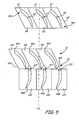
- FIG. 5 shows a schematic top view of fan section 11 of FIG. 1 , showing variable pitch fan blades 12 of FIG. 2 and variable camber fan blades 14 of FIG. 4 .
- Fan blades 12 are disposed within engine 10 such that they extend generally in the direction of centerline CL from leading edge 158 to trailing edge 160. Fan blades 12 are configured for rotation about pivot pins 64 on platforms 65.
- Fan blades 14 are disposed generally in the direction of centerline CL within engine 10, with upstream blade sections 45A forming the leading edge of each blade 14, and downstream blade sections 45B forming the trailing edge of each blade 14.
- Downstream blade sections 45B are configured for rotation about pivot pins 122 on platforms 120, while upstream blade sections 45A fixedly extend from platforms 119.
- engine 10 includes about thirty to about forty of first-stage blades 12 and second-stage blades 14 disposed circumferentially about shaft 24 and rotors 48A and 48B, respectively.
- Variable pitch blades 12 are rotated about pivot pins 64 to control the surge margin. For example, when engine 10 is started blades 12 are rotated such that airflow through variable pitch blades 12 is partially closed, as only small amounts of air are required for combustion. As engine 10 is brought up to speed and during operation of engine 10, variable pitch blades 12 are opened up to let additional airflow through to the combustors. When electronic engine controls detect an impending surge, variable pitch blades 12 are rotated to close airflow through blades 12. Thus, actuation of variable pitch blades 12 is integrated with full-authority, digital electronic control systems of engine 10 to coordinate operation of engine 10.
- variable camber blades 14 actuation of variable camber blades 14 is coordinated with the full-authority, digital electric control system of engine 10.
- Downstream blade sections 45B are rotated about pivot pins 122 to control the surge margin within engine 10.
- Downstream blade sections 45B are positioned downstream of upstream blade sections 45A such that together they form an airfoil body.
- Downstream blade sections 45B are positioned downstream of upstream blade sections 45A such that they slightly overlap in the axial direction.
- Downstream blade sections 45B are positioned slightly to the pressure side of upstream blade sections 45A such that there is a small gap between upstream blade section 45A and 45B.
- Platforms 119 of upstream blade sections 45A include notches 162 and 164 that conform around the leading edge portions of downstream blade sections 45B.
- downstream blade sections 45B are placed in different positions with respect to upstream blade sections 45A.
- downstream blade sections 45B may be placed directly behind the trailing edge portions of upstream blade sections 45A such that no gaps are present.
- downstream blade sections 45B are rotatable about pivot pins 122. Accordingly, the curvature of blades 14 is altered to differentiate the pressure profile from upstream portion 45A to downstream portion 45B. For example, as downstream portions 45B are rotated clockwise as shown in FIG. 5 , the curvature of blades 14 increases such that the pressure at downstream portions 45B is increased. As such, blades 14 do more work and more air is pushed through fan section 11.
- downstream blade sections 45B can be rotated counterclockwise to increase the pressure in fan section 11 to prevent the back flow of air through engine 10.
- blades 12 and blades 14 are able to operate efficiently at off-point operation of engine 10.
Landscapes
- Engineering & Computer Science (AREA)
- Mechanical Engineering (AREA)
- General Engineering & Computer Science (AREA)
- Structures Of Non-Positive Displacement Pumps (AREA)
- Control Of Turbines (AREA)
Applications Claiming Priority (1)
| Application Number | Priority Date | Filing Date | Title |
|---|---|---|---|
| US11/709,013 US7901185B2 (en) | 2007-02-21 | 2007-02-21 | Variable rotor blade for gas turbine engine |
Publications (3)
| Publication Number | Publication Date |
|---|---|
| EP1961919A2 true EP1961919A2 (fr) | 2008-08-27 |
| EP1961919A3 EP1961919A3 (fr) | 2011-12-28 |
| EP1961919B1 EP1961919B1 (fr) | 2017-11-01 |
Family
ID=39362514
Family Applications (1)
| Application Number | Title | Priority Date | Filing Date |
|---|---|---|---|
| EP08250587.6A Active EP1961919B1 (fr) | 2007-02-21 | 2008-02-20 | Mécanisme de réglage pour une aube de rotor dans une turbine à gaz |
Country Status (2)
| Country | Link |
|---|---|
| US (1) | US7901185B2 (fr) |
| EP (1) | EP1961919B1 (fr) |
Cited By (27)
| Publication number | Priority date | Publication date | Assignee | Title |
|---|---|---|---|---|
| WO2009142973A2 (fr) * | 2008-05-13 | 2009-11-26 | Rotating Composite Technologies Llc | Dispositif de retenue de pale de ventilateur et système de pas variable |
| FR2992376A1 (fr) * | 2012-06-25 | 2013-12-27 | Snecma | Soufflante a calage variable par rotation differentielle des disques de soufflante |
| EP2524866A3 (fr) * | 2011-05-16 | 2017-07-12 | Rolls-Royce plc | Rotor d'hélice à pas variable |
| WO2017148177A1 (fr) * | 2016-03-04 | 2017-09-08 | 太原理工大学 | Dispositif d'ajustement de pale à deux étages pour ventilateur à écoulement axial à contre-rotation |
| EP3222822A1 (fr) * | 2016-03-24 | 2017-09-27 | United Technologies Corporation | Commande d'actionnement d' engrenage à onde de déformation pour aubes variables |
| EP3222823A3 (fr) * | 2016-03-24 | 2017-10-04 | United Technologies Corporation | Commande d'actionnement d' engrenage à onde de déformation pour aubes variables multi-étages |
| EP3228823A1 (fr) * | 2016-03-24 | 2017-10-11 | United Technologies Corporation | Actionnement de roue dentée coulissante pour aubes variables |
| EP3228822A1 (fr) * | 2016-03-24 | 2017-10-11 | United Technologies Corporation | Actionnement d'aube variable avec bague tournante et liens glissants |
| EP3228824A1 (fr) * | 2016-03-24 | 2017-10-11 | United Technologies Corporation | Actionnement électrique pour aubes variables |
| EP3236016A1 (fr) * | 2016-03-24 | 2017-10-25 | United Technologies Corporation | Arbre d'entraînement pour actionner une aube variable à distance |
| EP3236015A1 (fr) * | 2016-03-24 | 2017-10-25 | United Technologies Corporation | Actionnement de câble pour aubes variables |
| EP3241996A1 (fr) * | 2016-03-24 | 2017-11-08 | United Technologies Corporation | Actionnement pour aubes variables |
| EP3241997A1 (fr) * | 2016-03-24 | 2017-11-08 | United Technologies Corporation | Anneau de conjugaison à engrenages pour un actionnement à aube variable |
| EP3244018A1 (fr) * | 2016-03-24 | 2017-11-15 | United Technologies Corporation | Anneau de conjugaison à engrenages pour un actionnement de aubes directrices variables multi-étages |
| EP3236017A3 (fr) * | 2016-03-24 | 2017-11-15 | United Technologies Corporation | Arbres concentriques pour actionner une aube variable à distance de manière indépendante |
| US10473593B1 (en) | 2018-05-04 | 2019-11-12 | United Technologies Corporation | System and method for damage detection by cast shadows |
| US10488371B1 (en) | 2018-05-04 | 2019-11-26 | United Technologies Corporation | Nondestructive inspection using thermoacoustic imagery and method therefor |
| US10685433B2 (en) | 2018-05-04 | 2020-06-16 | Raytheon Technologies Corporation | Nondestructive coating imperfection detection system and method therefor |
| US10902664B2 (en) | 2018-05-04 | 2021-01-26 | Raytheon Technologies Corporation | System and method for detecting damage using two-dimensional imagery and three-dimensional model |
| EP3770064A1 (fr) * | 2019-07-26 | 2021-01-27 | Hamilton Sundstrand Corporation | Changement et contrôle électriques de pas de pale d'hélice d'aéronef |
| US10914191B2 (en) | 2018-05-04 | 2021-02-09 | Raytheon Technologies Corporation | System and method for in situ airfoil inspection |
| CN112373721A (zh) * | 2020-11-03 | 2021-02-19 | 哈尔滨飞机工业集团有限责任公司 | 一种直升机地面状态下主桨舵机基准调整方法 |
| US10928362B2 (en) | 2018-05-04 | 2021-02-23 | Raytheon Technologies Corporation | Nondestructive inspection using dual pulse-echo ultrasonics and method therefor |
| US10943320B2 (en) | 2018-05-04 | 2021-03-09 | Raytheon Technologies Corporation | System and method for robotic inspection |
| US10958843B2 (en) | 2018-05-04 | 2021-03-23 | Raytheon Technologies Corporation | Multi-camera system for simultaneous registration and zoomed imagery |
| US11079285B2 (en) | 2018-05-04 | 2021-08-03 | Raytheon Technologies Corporation | Automated analysis of thermally-sensitive coating and method therefor |
| US11268881B2 (en) | 2018-05-04 | 2022-03-08 | Raytheon Technologies Corporation | System and method for fan blade rotor disk and gear inspection |
Families Citing this family (14)
| Publication number | Priority date | Publication date | Assignee | Title |
|---|---|---|---|---|
| US8235324B1 (en) * | 2009-03-03 | 2012-08-07 | Orbital Research Inc. | Rotorcraft with electrically driven blade control |
| US9470153B2 (en) * | 2011-10-05 | 2016-10-18 | United Technologies Corporation | Combined pump system for engine TMS AOC reduction and ECS loss elimination |
| US10329923B2 (en) * | 2014-03-10 | 2019-06-25 | United Technologies Corporation | Gas turbine engine airfoil leading edge cooling |
| US10288083B2 (en) | 2015-11-16 | 2019-05-14 | General Electric Company | Pitch range for a variable pitch fan |
| US11073160B2 (en) | 2016-09-08 | 2021-07-27 | The United States Of America As Represented By The Secretary Of The Army | Adaptable articulating axial-flow compressor/turbine rotor blade |
| US10618667B2 (en) | 2016-10-31 | 2020-04-14 | Rolls-Royce Corporation | Fan module with adjustable pitch blades and power system |
| US10737801B2 (en) * | 2016-10-31 | 2020-08-11 | Rolls-Royce Corporation | Fan module with rotatable vane ring power system |
| US20180171877A1 (en) * | 2016-12-15 | 2018-06-21 | General Electric Company | Power Generation System and Method for Operating Same |
| US10753225B2 (en) * | 2017-03-31 | 2020-08-25 | The Boeing Company | Engine turning motor via pneumatic or hydraulic motor |
| US10415405B2 (en) * | 2017-04-21 | 2019-09-17 | United Technologies Corporation | Variable pitch fan blade system |
| GB201917171D0 (en) * | 2019-11-26 | 2020-01-08 | Rolls Royce Plc | Gas turbine engine |
| US11946437B2 (en) | 2021-02-15 | 2024-04-02 | General Electric Company | Variable pitch fans for turbomachinery engines |
| US11454195B2 (en) | 2021-02-15 | 2022-09-27 | General Electric Company | Variable pitch fans for turbomachinery engines |
| CN113682462A (zh) * | 2021-09-18 | 2021-11-23 | 上海交通大学 | 推进装置及其可调进口预旋导叶电驱动涵道风扇推进系统 |
Citations (6)
| Publication number | Priority date | Publication date | Assignee | Title |
|---|---|---|---|---|
| CH461015A (de) * | 1965-02-27 | 1968-08-15 | Meissen Turbowerke | Spaltflügelrad für axiale Strömungsmaschinen sowie dessen Verwendung für Lüfter und Gebläse |
| US3893789A (en) * | 1973-02-21 | 1975-07-08 | United Aircraft Corp | Pitch change actuator for a variable pitch fan propulsor |
| US4599041A (en) * | 1984-12-19 | 1986-07-08 | Stricker John G | Variable camber tandem blade bow for turbomachines |
| US5249924A (en) * | 1992-02-21 | 1993-10-05 | Southwest Aerospace Corporation | RAM air turbine |
| DE10137230C1 (de) * | 2001-07-30 | 2003-04-24 | Jens Falkenstein | Elektrisch angetriebenes Spannungswellen-Getriebe |
| WO2006086342A2 (fr) * | 2005-02-07 | 2006-08-17 | Aerocomposites, Inc. | Pale de rotor a pas variable presentant des doubles elements de retenue souples |
Family Cites Families (21)
| Publication number | Priority date | Publication date | Assignee | Title |
|---|---|---|---|---|
| DE2250473C2 (de) * | 1972-10-14 | 1974-11-28 | Klein, Schanzlin & Becker Ag, 6710 Frankenthal | Axiale bzw. halbaxiale, vertikale Kreiseim aschine |
| US3900274A (en) * | 1974-06-25 | 1975-08-19 | Gen Electric | Remote controlled actuation system for the rotor of a gas turbine engine |
| US4021142A (en) | 1974-10-09 | 1977-05-03 | United Technologies Corporation | Pitch-change apparatus for a ducted thrust fan |
| US4124330A (en) | 1974-10-09 | 1978-11-07 | United Technologies Corporation | Cam-operated pitch-change apparatus |
| US3986794A (en) * | 1975-06-09 | 1976-10-19 | General Motors Corporation | Reversible ducted fan assembly |
| US4053256A (en) | 1975-09-29 | 1977-10-11 | United Technologies Corporation | Variable camber vane for a gas turbine engine |
| US4619580A (en) | 1983-09-08 | 1986-10-28 | The Boeing Company | Variable camber vane and method therefor |
| US4750862A (en) | 1986-11-28 | 1988-06-14 | United Technologies Corporation | Modular propeller blade pitch actuation system |
| US5022825A (en) | 1988-10-07 | 1991-06-11 | United Technologies Corporation | Pitch retention member |
| US5163817A (en) | 1989-10-16 | 1992-11-17 | United Technologies Corporation | Rotor blade retention |
| FR2707338B1 (fr) | 1993-07-07 | 1995-08-11 | Snecma | Aube de turbomachine à cambrure variable. |
| FR2712250B1 (fr) * | 1993-11-10 | 1995-12-29 | Hispano Suiza Sa | Procédé et dispositif de commande de variation du pas des pales d'un rotor. |
| US5795132A (en) | 1995-04-07 | 1998-08-18 | Something Else Limited Liability Co. | Variable pitch propeller |
| US5745558A (en) * | 1995-10-27 | 1998-04-28 | United States Advanced Network, Inc. | Three-way call detection and response system |
| US6015264A (en) | 1997-08-15 | 2000-01-18 | United Technologies Corporation | Preloaded retention assembly for aircraft propeller blade retention |
| GB2339244B (en) | 1998-06-19 | 2002-12-18 | Rolls Royce Plc | A variable camber vane |
| US6305905B1 (en) | 1999-05-05 | 2001-10-23 | United Technologies Corporation | Bolted-on propeller blade |
| US6676080B2 (en) | 2000-07-19 | 2004-01-13 | Aero Composites, Inc. | Composite airfoil assembly |
| US7086230B2 (en) | 2000-08-21 | 2006-08-08 | Brp-Rotax Gmbh & Co. Kg | Pop-off valve for an aircraft engine having a turbocharger control system and propeller control system by stepper motor |
| JP2003065080A (ja) | 2001-08-28 | 2003-03-05 | Honda Motor Co Ltd | ガスタービン・エンジンの制御装置 |
| US7114911B2 (en) | 2004-08-25 | 2006-10-03 | General Electric Company | Variable camber and stagger airfoil and method |
-
2007
- 2007-02-21 US US11/709,013 patent/US7901185B2/en not_active Expired - Fee Related
-
2008
- 2008-02-20 EP EP08250587.6A patent/EP1961919B1/fr active Active
Patent Citations (6)
| Publication number | Priority date | Publication date | Assignee | Title |
|---|---|---|---|---|
| CH461015A (de) * | 1965-02-27 | 1968-08-15 | Meissen Turbowerke | Spaltflügelrad für axiale Strömungsmaschinen sowie dessen Verwendung für Lüfter und Gebläse |
| US3893789A (en) * | 1973-02-21 | 1975-07-08 | United Aircraft Corp | Pitch change actuator for a variable pitch fan propulsor |
| US4599041A (en) * | 1984-12-19 | 1986-07-08 | Stricker John G | Variable camber tandem blade bow for turbomachines |
| US5249924A (en) * | 1992-02-21 | 1993-10-05 | Southwest Aerospace Corporation | RAM air turbine |
| DE10137230C1 (de) * | 2001-07-30 | 2003-04-24 | Jens Falkenstein | Elektrisch angetriebenes Spannungswellen-Getriebe |
| WO2006086342A2 (fr) * | 2005-02-07 | 2006-08-17 | Aerocomposites, Inc. | Pale de rotor a pas variable presentant des doubles elements de retenue souples |
Cited By (48)
| Publication number | Priority date | Publication date | Assignee | Title |
|---|---|---|---|---|
| WO2009142973A3 (fr) * | 2008-05-13 | 2010-01-21 | Rotating Composite Technologies Llc | Dispositif de retenue de pale de ventilateur et système de pas variable |
| US8075270B2 (en) | 2008-05-13 | 2011-12-13 | Rotating Composite Technologies Llc | Fan blade retention and variable pitch system |
| WO2009142973A2 (fr) * | 2008-05-13 | 2009-11-26 | Rotating Composite Technologies Llc | Dispositif de retenue de pale de ventilateur et système de pas variable |
| EP2524866A3 (fr) * | 2011-05-16 | 2017-07-12 | Rolls-Royce plc | Rotor d'hélice à pas variable |
| RU2644001C2 (ru) * | 2012-06-25 | 2018-02-06 | Снекма | Вентилятор с изменяемым углом установки путем различного вращения дисков вентилятора |
| FR2992376A1 (fr) * | 2012-06-25 | 2013-12-27 | Snecma | Soufflante a calage variable par rotation differentielle des disques de soufflante |
| WO2014001701A1 (fr) * | 2012-06-25 | 2014-01-03 | Snecma | Soufflante a calage variable par rotation differentielle des disques de soufflante |
| US9695703B2 (en) | 2012-06-25 | 2017-07-04 | Snecma | Fan having a variable setting by means of differential rotation of the fan disks |
| WO2017148177A1 (fr) * | 2016-03-04 | 2017-09-08 | 太原理工大学 | Dispositif d'ajustement de pale à deux étages pour ventilateur à écoulement axial à contre-rotation |
| US10612559B2 (en) | 2016-03-04 | 2020-04-07 | Taiyuan University Of Technology | Two-stage blade adjusting device for counter-rotating axial flow fan |
| US10301962B2 (en) | 2016-03-24 | 2019-05-28 | United Technologies Corporation | Harmonic drive for shaft driving multiple stages of vanes via gears |
| US10443431B2 (en) | 2016-03-24 | 2019-10-15 | United Technologies Corporation | Idler gear connection for multi-stage variable vane actuation |
| EP3228824A1 (fr) * | 2016-03-24 | 2017-10-11 | United Technologies Corporation | Actionnement électrique pour aubes variables |
| EP3236016A1 (fr) * | 2016-03-24 | 2017-10-25 | United Technologies Corporation | Arbre d'entraînement pour actionner une aube variable à distance |
| EP3236015A1 (fr) * | 2016-03-24 | 2017-10-25 | United Technologies Corporation | Actionnement de câble pour aubes variables |
| EP3241996A1 (fr) * | 2016-03-24 | 2017-11-08 | United Technologies Corporation | Actionnement pour aubes variables |
| EP3241997A1 (fr) * | 2016-03-24 | 2017-11-08 | United Technologies Corporation | Anneau de conjugaison à engrenages pour un actionnement à aube variable |
| EP3244018A1 (fr) * | 2016-03-24 | 2017-11-15 | United Technologies Corporation | Anneau de conjugaison à engrenages pour un actionnement de aubes directrices variables multi-étages |
| EP3236017A3 (fr) * | 2016-03-24 | 2017-11-15 | United Technologies Corporation | Arbres concentriques pour actionner une aube variable à distance de manière indépendante |
| EP3228823A1 (fr) * | 2016-03-24 | 2017-10-11 | United Technologies Corporation | Actionnement de roue dentée coulissante pour aubes variables |
| US10107130B2 (en) | 2016-03-24 | 2018-10-23 | United Technologies Corporation | Concentric shafts for remote independent variable vane actuation |
| US10190599B2 (en) | 2016-03-24 | 2019-01-29 | United Technologies Corporation | Drive shaft for remote variable vane actuation |
| US10288087B2 (en) | 2016-03-24 | 2019-05-14 | United Technologies Corporation | Off-axis electric actuation for variable vanes |
| US10294813B2 (en) | 2016-03-24 | 2019-05-21 | United Technologies Corporation | Geared unison ring for variable vane actuation |
| EP3222823A3 (fr) * | 2016-03-24 | 2017-10-04 | United Technologies Corporation | Commande d'actionnement d' engrenage à onde de déformation pour aubes variables multi-étages |
| US10329946B2 (en) | 2016-03-24 | 2019-06-25 | United Technologies Corporation | Sliding gear actuation for variable vanes |
| US10329947B2 (en) | 2016-03-24 | 2019-06-25 | United Technologies Corporation | 35Geared unison ring for multi-stage variable vane actuation |
| US10415596B2 (en) | 2016-03-24 | 2019-09-17 | United Technologies Corporation | Electric actuation for variable vanes |
| US10443430B2 (en) | 2016-03-24 | 2019-10-15 | United Technologies Corporation | Variable vane actuation with rotating ring and sliding links |
| EP3228822A1 (fr) * | 2016-03-24 | 2017-10-11 | United Technologies Corporation | Actionnement d'aube variable avec bague tournante et liens glissants |
| US10458271B2 (en) | 2016-03-24 | 2019-10-29 | United Technologies Corporation | Cable drive system for variable vane operation |
| US11131323B2 (en) | 2016-03-24 | 2021-09-28 | Raytheon Technologies Corporation | Harmonic drive for shaft driving multiple stages of vanes via gears |
| EP3222822A1 (fr) * | 2016-03-24 | 2017-09-27 | United Technologies Corporation | Commande d'actionnement d' engrenage à onde de déformation pour aubes variables |
| US11079285B2 (en) | 2018-05-04 | 2021-08-03 | Raytheon Technologies Corporation | Automated analysis of thermally-sensitive coating and method therefor |
| US10958843B2 (en) | 2018-05-04 | 2021-03-23 | Raytheon Technologies Corporation | Multi-camera system for simultaneous registration and zoomed imagery |
| US10902664B2 (en) | 2018-05-04 | 2021-01-26 | Raytheon Technologies Corporation | System and method for detecting damage using two-dimensional imagery and three-dimensional model |
| US11880904B2 (en) | 2018-05-04 | 2024-01-23 | Rtx Corporation | System and method for robotic inspection |
| US10914191B2 (en) | 2018-05-04 | 2021-02-09 | Raytheon Technologies Corporation | System and method for in situ airfoil inspection |
| US11268881B2 (en) | 2018-05-04 | 2022-03-08 | Raytheon Technologies Corporation | System and method for fan blade rotor disk and gear inspection |
| US10685433B2 (en) | 2018-05-04 | 2020-06-16 | Raytheon Technologies Corporation | Nondestructive coating imperfection detection system and method therefor |
| US10943320B2 (en) | 2018-05-04 | 2021-03-09 | Raytheon Technologies Corporation | System and method for robotic inspection |
| US10928362B2 (en) | 2018-05-04 | 2021-02-23 | Raytheon Technologies Corporation | Nondestructive inspection using dual pulse-echo ultrasonics and method therefor |
| US10488371B1 (en) | 2018-05-04 | 2019-11-26 | United Technologies Corporation | Nondestructive inspection using thermoacoustic imagery and method therefor |
| US10473593B1 (en) | 2018-05-04 | 2019-11-12 | United Technologies Corporation | System and method for damage detection by cast shadows |
| US11312477B2 (en) | 2019-07-26 | 2022-04-26 | Hamilton Sundstrand Corporation | Aircraft propeller electric blade pitch change and control |
| EP3770064A1 (fr) * | 2019-07-26 | 2021-01-27 | Hamilton Sundstrand Corporation | Changement et contrôle électriques de pas de pale d'hélice d'aéronef |
| CN112373721A (zh) * | 2020-11-03 | 2021-02-19 | 哈尔滨飞机工业集团有限责任公司 | 一种直升机地面状态下主桨舵机基准调整方法 |
| CN112373721B (zh) * | 2020-11-03 | 2023-02-10 | 哈尔滨飞机工业集团有限责任公司 | 一种直升机地面状态下主桨舵机基准调整方法 |
Also Published As
| Publication number | Publication date |
|---|---|
| US20080273976A1 (en) | 2008-11-06 |
| EP1961919A3 (fr) | 2011-12-28 |
| EP1961919B1 (fr) | 2017-11-01 |
| US7901185B2 (en) | 2011-03-08 |
Similar Documents
| Publication | Publication Date | Title |
|---|---|---|
| EP1961919B1 (fr) | Mécanisme de réglage pour une aube de rotor dans une turbine à gaz | |
| US20200309027A1 (en) | Gas turbine engine with an electromagnetic transmission | |
| US4968217A (en) | Variable pitch arrangement for a gas turbine engine | |
| US7628579B2 (en) | Gear train variable vane synchronizing mechanism for inner diameter vane shroud | |
| EP1808579B1 (fr) | Système d'actionnement pour aubes de stator variables | |
| US7588415B2 (en) | Synch ring variable vane synchronizing mechanism for inner diameter vane shroud | |
| EP2472066B1 (fr) | Aubage statorique à géométrie variable pour moteur à turbine à gaz et moteur à turbine à gaz associé | |
| US7882694B2 (en) | Variable fan inlet guide vane assembly for gas turbine engine | |
| US5993152A (en) | Nonlinear vane actuation | |
| EP2615289B1 (fr) | Turboréacteur à double flux avec compresseur entraîné par engrenage et noyau entrainé par ventilateur | |
| US9963981B2 (en) | Pitch change mechanism for shrouded fan with low fan pressure ratio | |
| US11952947B2 (en) | Hybrid electric fan with stall free low pressure compressor | |
| EP3176382B1 (fr) | Système de commande de jeu d'extrémité de turbine à réactivité élevée | |
| CN111279060A (zh) | 混合传动涡轮发动机 | |
| EP3019709B1 (fr) | Dispositif de commande mécanique pour système d'engrenage d'entraînement de ventilateur | |
| US20130223984A1 (en) | Multi-Stage Axial Compressor with Counter-Rotation | |
| EP2914817B1 (fr) | Bague de synchronisation de moteur de turbine à gaz | |
| US20240035392A1 (en) | After-fan system with electrical motor for gas turbine engines | |
| EP3633152B1 (fr) | Turboréacteur à double flux comportant une aube directrice d'entrée rotative motorisée | |
| EP3633151A1 (fr) | Diffuseur à géométrie variable | |
| EP3078815B1 (fr) | Commande de jeu active pour systèmes de rotors axiaux | |
| EP3623586B1 (fr) | Soufflante à rapport de dérivation variable dotée d'un aubage de rotor arrière à pas variable | |
| EP3578761A1 (fr) | Compresseur d'un moteur à turbine à gaz avec un agencement d'aube de stator à calage variable | |
| CN112443364A (zh) | 用于同心可变定子静叶的促动组件 | |
| EP3594476B1 (fr) | Agencement de montage de moteur à turbine à gaz à turbosoufflante à engrenage |
Legal Events
| Date | Code | Title | Description |
|---|---|---|---|
| PUAI | Public reference made under article 153(3) epc to a published international application that has entered the european phase |
Free format text: ORIGINAL CODE: 0009012 |
|
| AK | Designated contracting states |
Kind code of ref document: A2 Designated state(s): AT BE BG CH CY CZ DE DK EE ES FI FR GB GR HR HU IE IS IT LI LT LU LV MC MT NL NO PL PT RO SE SI SK TR |
|
| AX | Request for extension of the european patent |
Extension state: AL BA MK RS |
|
| PUAL | Search report despatched |
Free format text: ORIGINAL CODE: 0009013 |
|
| AK | Designated contracting states |
Kind code of ref document: A3 Designated state(s): AT BE BG CH CY CZ DE DK EE ES FI FR GB GR HR HU IE IS IT LI LT LU LV MC MT NL NO PL PT RO SE SI SK TR |
|
| AX | Request for extension of the european patent |
Extension state: AL BA MK RS |
|
| RIC1 | Information provided on ipc code assigned before grant |
Ipc: F04D 29/36 20060101ALI20111124BHEP Ipc: F01D 7/02 20060101AFI20111124BHEP Ipc: F01D 5/14 20060101ALI20111124BHEP |
|
| 17P | Request for examination filed |
Effective date: 20120627 |
|
| AKX | Designation fees paid |
Designated state(s): DE GB |
|
| RAP1 | Party data changed (applicant data changed or rights of an application transferred) |
Owner name: UNITED TECHNOLOGIES CORPORATION |
|
| GRAP | Despatch of communication of intention to grant a patent |
Free format text: ORIGINAL CODE: EPIDOSNIGR1 |
|
| INTG | Intention to grant announced |
Effective date: 20161116 |
|
| GRAJ | Information related to disapproval of communication of intention to grant by the applicant or resumption of examination proceedings by the epo deleted |
Free format text: ORIGINAL CODE: EPIDOSDIGR1 |
|
| GRAJ | Information related to disapproval of communication of intention to grant by the applicant or resumption of examination proceedings by the epo deleted |
Free format text: ORIGINAL CODE: EPIDOSDIGR1 |
|
| GRAL | Information related to payment of fee for publishing/printing deleted |
Free format text: ORIGINAL CODE: EPIDOSDIGR3 |
|
| GRAS | Grant fee paid |
Free format text: ORIGINAL CODE: EPIDOSNIGR3 |
|
| INTC | Intention to grant announced (deleted) | ||
| INTC | Intention to grant announced (deleted) | ||
| GRAR | Information related to intention to grant a patent recorded |
Free format text: ORIGINAL CODE: EPIDOSNIGR71 |
|
| GRAA | (expected) grant |
Free format text: ORIGINAL CODE: 0009210 |
|
| AK | Designated contracting states |
Kind code of ref document: B1 Designated state(s): DE GB |
|
| INTG | Intention to grant announced |
Effective date: 20170922 |
|
| REG | Reference to a national code |
Ref country code: GB Ref legal event code: FG4D |
|
| REG | Reference to a national code |
Ref country code: DE Ref legal event code: R096 Ref document number: 602008052736 Country of ref document: DE |
|
| REG | Reference to a national code |
Ref country code: DE Ref legal event code: R097 Ref document number: 602008052736 Country of ref document: DE |
|
| PLBE | No opposition filed within time limit |
Free format text: ORIGINAL CODE: 0009261 |
|
| STAA | Information on the status of an ep patent application or granted ep patent |
Free format text: STATUS: NO OPPOSITION FILED WITHIN TIME LIMIT |
|
| 26N | No opposition filed |
Effective date: 20180802 |
|
| REG | Reference to a national code |
Ref country code: DE Ref legal event code: R081 Ref document number: 602008052736 Country of ref document: DE Owner name: RAYTHEON TECHNOLOGIES CORPORATION (N.D.GES.D.S, US Free format text: FORMER OWNER: UNITED TECHNOLOGIES CORPORATION, FARMINGTON, CONN., US |
|
| PGFP | Annual fee paid to national office [announced via postgrant information from national office to epo] |
Ref country code: GB Payment date: 20230121 Year of fee payment: 16 Ref country code: DE Payment date: 20230119 Year of fee payment: 16 |
|
| P01 | Opt-out of the competence of the unified patent court (upc) registered |
Effective date: 20230519 |