EP1961575A2 - Sensor zur Erkennung der verbleibenden Menge und Tintenstrahldrucker damit - Google Patents
Sensor zur Erkennung der verbleibenden Menge und Tintenstrahldrucker damit Download PDFInfo
- Publication number
- EP1961575A2 EP1961575A2 EP08250608A EP08250608A EP1961575A2 EP 1961575 A2 EP1961575 A2 EP 1961575A2 EP 08250608 A EP08250608 A EP 08250608A EP 08250608 A EP08250608 A EP 08250608A EP 1961575 A2 EP1961575 A2 EP 1961575A2
- Authority
- EP
- European Patent Office
- Prior art keywords
- electrode
- remaining amount
- amount detection
- detection
- ink
- Prior art date
- Legal status (The legal status is an assumption and is not a legal conclusion. Google has not performed a legal analysis and makes no representation as to the accuracy of the status listed.)
- Granted
Links
Images


Classifications
-
- B—PERFORMING OPERATIONS; TRANSPORTING
- B41—PRINTING; LINING MACHINES; TYPEWRITERS; STAMPS
- B41J—TYPEWRITERS; SELECTIVE PRINTING MECHANISMS, i.e. MECHANISMS PRINTING OTHERWISE THAN FROM A FORME; CORRECTION OF TYPOGRAPHICAL ERRORS
- B41J2/00—Typewriters or selective printing mechanisms characterised by the printing or marking process for which they are designed
- B41J2/005—Typewriters or selective printing mechanisms characterised by the printing or marking process for which they are designed characterised by bringing liquid or particles selectively into contact with a printing material
- B41J2/01—Ink jet
- B41J2/17—Ink jet characterised by ink handling
- B41J2/175—Ink supply systems ; Circuit parts therefor
- B41J2/17566—Ink level or ink residue control
-
- B—PERFORMING OPERATIONS; TRANSPORTING
- B41—PRINTING; LINING MACHINES; TYPEWRITERS; STAMPS
- B41J—TYPEWRITERS; SELECTIVE PRINTING MECHANISMS, i.e. MECHANISMS PRINTING OTHERWISE THAN FROM A FORME; CORRECTION OF TYPOGRAPHICAL ERRORS
- B41J2/00—Typewriters or selective printing mechanisms characterised by the printing or marking process for which they are designed
- B41J2/005—Typewriters or selective printing mechanisms characterised by the printing or marking process for which they are designed characterised by bringing liquid or particles selectively into contact with a printing material
- B41J2/01—Ink jet
- B41J2/17—Ink jet characterised by ink handling
- B41J2/175—Ink supply systems ; Circuit parts therefor
- B41J2/17503—Ink cartridges
- B41J2/17513—Inner structure
-
- B—PERFORMING OPERATIONS; TRANSPORTING
- B41—PRINTING; LINING MACHINES; TYPEWRITERS; STAMPS
- B41J—TYPEWRITERS; SELECTIVE PRINTING MECHANISMS, i.e. MECHANISMS PRINTING OTHERWISE THAN FROM A FORME; CORRECTION OF TYPOGRAPHICAL ERRORS
- B41J2/00—Typewriters or selective printing mechanisms characterised by the printing or marking process for which they are designed
- B41J2/005—Typewriters or selective printing mechanisms characterised by the printing or marking process for which they are designed characterised by bringing liquid or particles selectively into contact with a printing material
- B41J2/01—Ink jet
- B41J2/17—Ink jet characterised by ink handling
- B41J2/175—Ink supply systems ; Circuit parts therefor
- B41J2/17503—Ink cartridges
- B41J2/17553—Outer structure
-
- G—PHYSICS
- G01—MEASURING; TESTING
- G01F—MEASURING VOLUME, VOLUME FLOW, MASS FLOW OR LIQUID LEVEL; METERING BY VOLUME
- G01F23/00—Indicating or measuring liquid level or level of fluent solid material, e.g. indicating in terms of volume or indicating by means of an alarm
- G01F23/22—Indicating or measuring liquid level or level of fluent solid material, e.g. indicating in terms of volume or indicating by means of an alarm by measuring physical variables, other than linear dimensions, pressure or weight, dependent on the level to be measured, e.g. by difference of heat transfer of steam or water
- G01F23/26—Indicating or measuring liquid level or level of fluent solid material, e.g. indicating in terms of volume or indicating by means of an alarm by measuring physical variables, other than linear dimensions, pressure or weight, dependent on the level to be measured, e.g. by difference of heat transfer of steam or water by measuring variations of capacity or inductance of capacitors or inductors arising from the presence of liquid or fluent solid material in the electric or electromagnetic fields
- G01F23/263—Indicating or measuring liquid level or level of fluent solid material, e.g. indicating in terms of volume or indicating by means of an alarm by measuring physical variables, other than linear dimensions, pressure or weight, dependent on the level to be measured, e.g. by difference of heat transfer of steam or water by measuring variations of capacity or inductance of capacitors or inductors arising from the presence of liquid or fluent solid material in the electric or electromagnetic fields by measuring variations in capacitance of capacitors
- G01F23/266—Indicating or measuring liquid level or level of fluent solid material, e.g. indicating in terms of volume or indicating by means of an alarm by measuring physical variables, other than linear dimensions, pressure or weight, dependent on the level to be measured, e.g. by difference of heat transfer of steam or water by measuring variations of capacity or inductance of capacitors or inductors arising from the presence of liquid or fluent solid material in the electric or electromagnetic fields by measuring variations in capacitance of capacitors measuring circuits therefor
-
- G—PHYSICS
- G01—MEASURING; TESTING
- G01F—MEASURING VOLUME, VOLUME FLOW, MASS FLOW OR LIQUID LEVEL; METERING BY VOLUME
- G01F23/00—Indicating or measuring liquid level or level of fluent solid material, e.g. indicating in terms of volume or indicating by means of an alarm
- G01F23/22—Indicating or measuring liquid level or level of fluent solid material, e.g. indicating in terms of volume or indicating by means of an alarm by measuring physical variables, other than linear dimensions, pressure or weight, dependent on the level to be measured, e.g. by difference of heat transfer of steam or water
- G01F23/26—Indicating or measuring liquid level or level of fluent solid material, e.g. indicating in terms of volume or indicating by means of an alarm by measuring physical variables, other than linear dimensions, pressure or weight, dependent on the level to be measured, e.g. by difference of heat transfer of steam or water by measuring variations of capacity or inductance of capacitors or inductors arising from the presence of liquid or fluent solid material in the electric or electromagnetic fields
- G01F23/263—Indicating or measuring liquid level or level of fluent solid material, e.g. indicating in terms of volume or indicating by means of an alarm by measuring physical variables, other than linear dimensions, pressure or weight, dependent on the level to be measured, e.g. by difference of heat transfer of steam or water by measuring variations of capacity or inductance of capacitors or inductors arising from the presence of liquid or fluent solid material in the electric or electromagnetic fields by measuring variations in capacitance of capacitors
- G01F23/268—Indicating or measuring liquid level or level of fluent solid material, e.g. indicating in terms of volume or indicating by means of an alarm by measuring physical variables, other than linear dimensions, pressure or weight, dependent on the level to be measured, e.g. by difference of heat transfer of steam or water by measuring variations of capacity or inductance of capacitors or inductors arising from the presence of liquid or fluent solid material in the electric or electromagnetic fields by measuring variations in capacitance of capacitors mounting arrangements of probes
Definitions
- the present invention relates to a remaining amount detection sensor for detecting a remaining amount of content of a container, and an ink-jet printer using the same.
- an ink-jet printer for performing image recording and the like by discharging ink from an ink-jet head
- a remaining amount of ink contained in an ink tank for supplying ink to the ink-jet head is monitored. Then, when the ink remaining amount decreases, ink is replenished from an ink replenishment tank, and in a case where the ink tank is a replaceable cartridge, it is notified that a time for replacement of the ink tank approaches.
- a remaining amount detection sensor of a capacitance type is disposed outside the ink tank, thereby detecting the ink remaining amount.
- JP 08-197749 A discloses an ink-jet printer which includes an ink tank for storing conductive ink, electrodes for detecting an amount of ink contained in the ink tank, or detecting presence or absence of the ink in a noncontact manner, and a detection circuit for detecting a capacitance between the electrodes.
- the electrodes described in JP 08-197749 A are disposed so as to face each other through the ink tank.
- JP 09-166474 A discloses a remaining amount sensor in which a detection electrode, which is formed of two electrode patterns formed on one surface of a sensor substrate, is brought into close contact with an outside surface of an ink cartridge, to thereby obtain an output voltage corresponding to a remaining amount of ink contained in the ink cartridge based on a capacitance measured by using the two electrode patterns of the detection electrode.
- JP 09-166474 A discloses the detection electrode of two types, that is, a type in which two detection electrodes are formed in parallel with each other on one outside surface of the ink cartridge, and a type in which the electrodes are arranged so as to face each other through the ink cartridge.
- the remaining amount detection is performed utilizing a change in capacitance between the detection electrodes due to a change in remaining amount of the ink contained in the container.
- the two detection electrodes arranged in parallel with each other on the outside of the container, and the two detection electrodes sandwiching the container are affected by other conductive structures and electrical circuits disposed on the periphery of the detection circuit, so there arises a problem in that the capacitance is changed due to a change in surrounding environments and the like, and a measurement error or erroneous detection occurs.
- the change in capacitance of the ink tank due to the change in remaining amount of the ink to be detected is generally extremely small. Accordingly, the noise due to the external factors has a large effect on the measurement accuracy.
- the ink tank of the ink-jet printer is disposed near the electrical circuit for controlling discharge of the ink-jet head and controlling a movement mechanism and the like of the ink-jet head, is movably held on a recording medium, and is disposed near a movable member. As a result, an amount of noise to be generated due to the external factors is increased.
- ink tanks for each color are prepared for color recording, and the ink tanks are arranged in parallel with each other.
- detection electrodes for the ink tanks for different colors are adjacent to each other.
- the capacitance is formed also between detection electrodes of another adjacent remaining amount detection sensor, which causes an increase in measurement error.
- the remaining amount detection sensor and the ink tanks can be disposed to be spaced apart from other members and other remaining amount detection sensors which affect the capacitance, but there arises another problem in that the apparatus is increased in size.
- the present invention has been made in view of the above-mentioned problems, and therefore an object of the present invention is to provide a remaining amount detection sensor capable of detecting a remaining amount of content of a container with high accuracy, and an ink-jet printer using the same.
- a remaining amount detection sensor which is disposed outside a container to detect a remaining amount of content of the container, including: a detection electrode disposed so as to face the container; a first guard electrode disposed in the same plane as the detection electrode so as to surround an outer periphery of the detection electrode; and a second guard electrode which is disposed so as to face the detection electrode with a space in at least a range covering the detection electrode, and has the same potential as that of the first guard electrode, in which the remaining amount of the content of the container can be detected based on a capacitance to be measured by the detection electrode with the potentials of the first guard electrode and the second electrode each being set as a reference potential.
- the detection electrode is disposed so as to face the container. Further, the first guard electrode surrounds the outer periphery of the detection electrode.
- the second guard electrode which has the same potential as that of the first guard electrode, is disposed so as to face the detection electrode with a space in at least the range covering the detection electrode.
- the detection electrode includes a plurality of the detection electrodes formed at positions spaced apart from each other; the first guard electrode is in a state of surrounding an outer periphery of each of the plurality of detection electrodes; and the remaining amount of the content of the container can be detected in a plurality of levels based on capacitances to be measured by the plurality of detection electrodes.
- the first guard electrode is in the state of surrounding the outer periphery of each of the plurality of detection electrodes disposed at positions spaced apart from each other. Accordingly, each of the detection electrodes does not affect the measurement of the capacitance by each of the detection electrodes. The remaining amount of the content at each arrangement position can be detected by each of the detection electrodes, thereby making it possible to detect the remaining amount of the content in a plurality of levels with high accuracy.
- the remaining amount detection sensor further includes: a third guard electrode which has the same potential as that of each of the first guard electrode and the second guard electrode, and is disposed so as to face at least one of the first guard electrode and the second guard electrode with a space on an opposite side of the container; and a reference electrode disposed so as to be sandwiched in a range in which one of the first guard electrode and the second guard electrode, and the third electrode are opposed to each other.
- a reference electrode is sandwiched in the range in which at least one of the first guard electrode and the second guard electrode, and the third guard electrode, thereby being shielded from the external electric field, and is integrally formed on the side or on the rear side of the detection part which is formed of the detection electrode and the first and second guard electrodes.
- the reference electrode is disposed in a range in which the first guard electrode and the third guard electrode are opposed to each other, and is disposed in the same plane as the second guard electrode.
- the reference electrode is disposed in the same plane as the second guard electrode. Accordingly, a thinner remaining amount detection sensor can be formed as compared with a case of forming the reference electrode between the second guard electrode and the third guard electrode.
- the reference electrode and the second guard electrode can be formed as a conductive pattern in the same layer of the multilayer printed board, thereby making it possible to use a multilayer printed board with a small number of layers.
- the second guard electrode is disposed in a range covering each of the detection electrode and the first guard electrode; the third guard electrode is disposed in a range covering the second guard electrode; and the reference electrode is disposed so as to be sandwiched in a range in which the second guard electrode and the third guard electrode are opposed to each other.
- the reference electrode is sandwiched between the second and third guard electrode, thereby being shielded from the external electric field, and is integrally formed on the rear surface of the detection part formed of the detection electrode and the first and second guard electrodes.
- the second guard electrode is formed in the region covering the detection electrode and the first guard electrode
- the third guard electrode is formed in the range covering the second guard electrode, thereby more reliably reducing the effects of the environmental factors on the detection electrode and the reference electrode.
- the detection electrode, the first guard electrode, and the second guard electrode are each formed as a conductive pattern of a multilayer printed board; and the multilayer printed board has a remaining amount detection circuit integrally formed thereon, for measuring the capacitance of the detection electrode to generate a remaining amount detection output.
- the sensor part formed of the detection electrode and the first and second guard electrodes, and the remaining amount detection circuit are integrally formed on the multilayer printed board. As a result, the wiring from the detection electrode is shortened, and a remaining amount detection sensor resistant to noise can be formed.
- the detection electrode, the first guard electrode, the second guard electrode, the third guard electrode, and the reference electrode are each formed as a conductive pattern of a multilayer printed board; and the multilayer printed board has a remaining amount detection circuit integrally formed thereon, for measuring the capacitance of the detection electrode to generate a remaining amount detection output.
- the detection electrode, the first guard electrode, the second guard electrode, the third guard electrode, and the reference electrode are each formed as the conductive pattern on the multilayer printed board. Accordingly, the sensor part formed of the detection electrode and the first and second guard electrodes, and a reference capacitor formed of the reference electrode sandwiched between one of the first guard electrode and the second guard electrode, and the third guard electrode are integrally formed, and can be integrally formed with the remaining amount detection circuit. As a result, the wiring from the detection electrode is shortened, and the remaining amount detection sensor resistant to noise can be formed.
- the reference electrode in the case of forming the remaining amount detection circuit as a ⁇ C-V conversion circuit, the reference electrode enables formation of a reference capacitor resistant to noise and environmental fluctuation. Accordingly, a compact remaining amount detection sensor with higher accuracy can be obtained.
- an ink-jet printer includes: an ink-jet head for discharging ink; an ink tank for supplying the ink to the ink-jet head; and the remaining amount detection sensor according to any one of the first to seventh aspects of the present invention, which is disposed outside the ink tank.
- the remaining amount detection sensor according to any one of the first to seventh aspects of the present invention is provided. As a result, the same operations and effects as those described in any one of the first to seventh aspects of the present invention are obtained.
- the effects on the capacitance of the detection electrode from the side and the rear side thereof can be blocked or reduced.
- FIG. 1 is an explanatory block diagram schematically showing a general structure of the ink-jet printer using the remaining amount detection sensor according to the first embodiment of the present invention.
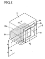
- FIG. 2 is a perspective view showing an arrangement state of the remaining amount detection sensor according to the first embodiment of the present invention.
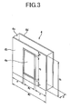
- FIG. 3 is a perspective view showing a structure of the remaining amount detection sensor according to the first embodiment of the present invention.
- FIG. 4 is a cross-sectional diagram of the remaining amount detection sensor according to the first embodiment of the present invention taken along the line A-A of FIG. 2 .
- FIG. 5 is a circuit diagram showing an example of a remaining amount detection circuit for taking out an output voltage from the remaining amount detection sensor according to the first embodiment of the present invention.
- an ink-jet printer 100 includes an ink-jet head 1, a sub-tank 3 (ink tank), a sensor holder 5, a remaining amount detection sensor 4, which are accommodated in a carriage 10 held so as to be relatively movable with respect to a surface of a recording medium (not shown), and a main tank 9 for supplying an ink 20 to the sub-tank 3.
- the ink-jet printer 100 performs image recording and the like by discharging ink droplets toward the recording medium.
- the ink-j et head 1 discharges ink droplets toward the recording medium from a head surface 1a on which a plurality of ink nozzles are arranged, and includes, inside thereof, known structures (not shown) such as an ink chamber and an ink discharge mechanism using a piezoelectric element.
- the ink-jet head 1 is connected to the sub-tank 3 through an ink tube 2 so as to be supplied with the ink 20 from the sub-tank 3.
- the ink-jet head 1 is fixed at a position of a height h H from a bottom surface 10a which is a reference surface of the carriage 10 in a height direction thereof.
- the sub-tank 3 is a container for storing a certain amount of the ink 20 as the content so as to supply the ink 20 to the ink-jet head 1 from a position near the ink-jet head 1.
- an ink tube 7 for introducing the ink 20 from the main tank 9 is connected, and to a lower side thereof, the ink tube 2 for supplying the stored ink 20 to the ink-jet head 1 is connected.
- the sub-tank 3 is detachably held by the sensor holder 5 which is fixed at a predetermined position in the carriage 10, and is fixed to be positioned with respect to the sensor holder 5 when the sub-tank 3 is mounted thereto.
- the sensor holder 5 is a holding member for detachably fixing the sub-tank 3 and for performing positioning of the sub-tank 3 in the carriage 10. Inside the sensor holder 5, there is provided the remaining amount detection sensor 4 which is urged by a pressure spring 6 to be brought into close contact with a side surface of the sub-tank 3 being mounted.
- a height of the sensor holder 5 being mounted is set so that a given meniscus shape is formed at the ink nozzles formed on the head surface 1a and an ink liquid level 20a in the sub-tank 3 is lower than the head surface 1a.
- a height h i of the ink liquid level 20a which is measured from the bottom surface 10a of the carriage 10, is represented as h i ⁇ h H .
- the remaining amount detection sensor 4 is disposed outside the side surface of the sub-tank 3, and detects the height of the ink liquid level 20a by measuring a capacitance on a side of the sub-tank 3, thereby detecting the remaining amount of the ink 20 contained in the sub-tank 3.
- the remaining amount detection sensor 4 has a structure in which an electrode pattern which is formed of a detection electrode 4a and a guard electrode 4b (first guard electrode), and a guard electrode 4d (second guard electrode) are disposed so as to face each other through a dielectric layer 4c with a thickness d.
- the remaining amount detection sensor 4 has a rectangular outer shape with a size of W 1 xH 1 which can be contained within a range of the side surface of the sub-tank 3.
- the remaining amount detection sensor 4 according to the first embodiment of the present invention is structured by using a double-sided printed board.
- a conductive pattern is formed on one substrate surface as the electrode pattern formed of the detection electrode 4a and the guard electrode 4b, and the guard electrode 4d is formed on the other substrate surface as a solid pattern.
- a base material of the printed board forms the dielectric layer 4c.
- a material of the double-sided printed board for example, a glass composite substrate and a glass epoxy substrate can be employed.
- the detection electrode 4a is provided at a substantial center of the surface on which a rectangular conductor layer with a long side H 2 and a short side W 2 (note that H 2 ⁇ H 1 and W 2 ⁇ W 1 ) is brought into close contact with the remaining amount detection sensor 4, thereby enabling detection of a potential via wiring (not shown).
- the long side of the detection electrode 4a is placed along a height direction of the sub-tank 3, that is, a vertical direction in which the ink liquid level 20a rises or falls.
- the guard electrode 4b is a conductive layer which is disposed in the same plane as the detection electrode 4a so as to surround an outer periphery of the detection electrode 4a and which is extended to an outer edge of the remaining amount detection sensor 4, that is, the rectangular outer shape having the size of W 1 xH 1 , and is grounded via wiring (not shown).
- the guard electrode 4d is a conductive layer which faces the detection electrode 4a and the guard electrode 4b and which covers the detection electrode 4a and the guard electrode 4b to be extended to the outer edge of the remaining amount detection sensor 4, and is grounded via wiring (not shown).
- wiring connected to the detection electrode 4a and a ground wire connected to each of the guard electrodes 4b and 4d are electrically connected to a remaining amount detection circuit part 11 (remaining amount detection circuit) for detecting the capacitance of the detection electrode 4a to thereby detect the remaining amount in the sub-tank 3.
- the remaining amount detection circuit part 11 may have any circuit configuration.
- a ⁇ C-V conversion circuit as shown in FIG. 5 is employed.
- the remaining amount detection circuit part 11 outputs a voltage V OUT obtained by converting, into a voltage, a difference ⁇ C in capacitance of a reference capacitor 31 having a known capacitance C ref and the capacitance C s of the detection electrode 4a.
- the remaining amount detection circuit part 11 includes an oscillator 30 for adding sine-wave signals to the remaining amount detection sensor 4 and the reference capacitor 31, a differential amplifier 32 for detecting a difference between the signals, a rectifier 33 for rectifying an output of the differential amplifier 32, and an amplifier 34 for amplifying the signals rectified by the rectifier 33.
- the differential amplifier 32 there can be employed a typical operational amplifier for comparing and calculating a voltage amplitude difference and a voltage phase difference, which are generated between both ends of the capacitance C s and the capacitance C ref , to output the difference.
- the capacitance C ref of the reference capacitor 31 is set to a value equal to a capacitance C S2 of the detection electrode 4a in a case where a position in the height direction with respect to the head surface 1a of the ink liquid level 20a in the sub-tank 3 matches an appropriate position L2 at which the given meniscus shape is formed at the ink nozzles of the ink-jet head 1.
- the remaining amount detection circuit part 11 is electrically connected to a pump drive control part 12 for controlling a pump-up operation of a lift pump 8 connected to the ink tube 7, and the output voltage V OUT is sent to the pump drive control part 12.
- the pump drive control part 12 can control driving, stopping, and a pump-up quantity of the lift pump 8 according to the position of the ink liquid level 20a to be detected based on the output voltage V OUT of the remaining amount detection circuit part 11.
- the pump drive control part 12 performs the control in the following manner.
- the output voltage V OUT is a negative value, that is, when the ink liquid level 20a is lower than the appropriate position L2
- the pump drive control part 12 drives the lift pump 8
- the output voltage V OUT is 0 or larger, that is, when the ink liquid level 20a reaches the appropriate position L2
- the pump drive control part 12 stops the lift pump 8. Accordingly, when the ink-jet head 1 consumes the ink 20 to thereby lower the ink liquid level 20a, replenishment of the ink 20 is automatically performed, thereby constantly maintaining the ink liquid level 20a at the appropriate position L2.
- the main tank 9 is a container for storing the ink 20 used for replenishing the ink 20, which is discharged from the ink-jet head 1 to be consumed, to the sub-tank 3, at a position apart from the carriage 10.
- the ink 20 contained in the main tank 9 is pumped up by the lift pump 8 and is supplied to the sub-tank 3 through the ink tube 7.
- FIG. 6 is a graph schematically showing a relation between the liquid level position in the container and the capacitance of the detection electrode of the remaining amount detection sensor according to the first embodiment of the present invention.
- An axis of abscissa represents the liquid level position and an axis of ordinate represents the capacitance to be detected.
- FIG. 7A is a conceptual diagram for explaining a range of the capacitance to be detected by the remaining amount detection sensor according to the embodiment of the present invention.
- FIG. 7B is a conceptual diagram for explaining a range of the capacitance to be detected by a remaining amount detection sensor according to a related art.
- the guard electrode 4b which is grounded, is disposed around the detection electrode 4a, and the guard electrode 4d, which is grounded, is disposed in a range covering the guard electrode 4b so as to face each of the detection electrode 4a and the guard electrode 4b.
- the capacitance of the detection electrode 4a on a side of the guard electrode 4d is constant, and an electric field outside the guard electrode 4d is shielded.
- the capacitance of the detection electrode 4a is not affected even when, for example, a positional relation with respect to components provided outside the guard electrode 4d.is changed by the movement of the carriage 10, other movable members, and the like. Further, even when an electrical circuit is provided near an external surface side of the guard electrode 4d, an effect of the electric field generated by the electrical circuit is blocked or reduced.
- the detection electrode 4a is adjacent to the guard electrode 4b through the sub-tank 3 and the ink 20 contained in the sub-tank 3.
- the capacitance of the detection electrode 4a is affected only by a change of a dielectric body provided in the space formed on the sub-tank 3 side near the surface of the detection electrode 4a, as shown in a region P indicated by the alternate long and two short dashes line of FIG. 7A .
- the capacitance of the detection electrode 50a is affected by peripheral dielectric bodies provided therearound in almost all the directions. Accordingly, as shown within a range of a region Q, the capacitance of the detection electrode 50a is affected also by the dielectric body provided outside the sub-tank 3 to the same degree as the sub-tank 3 and the dielectric body inside the sub-tank 3.
- the capacitance of the detection electrode 50a is to be changed.
- the detection electrode 50a is affected also by the electric field of the electrical circuit disposed near the detection electrode 50a because the electric field outside the detection electrode 50a is not shielded.
- the capacitance is increased according to the rise of the ink liquid level 20a.
- the capacitance is substantially linearly and monotonously increased from C s 1 to C s 2 to and C s 3.
- the remaining amount detection sensor 4 can detect, as the output voltage V OUT of the remaining amount detection circuit part 11, the change in capacitance of the detection electrode 4a, which corresponds to the height of the ink liquid level 20a.
- the remaining amount detection sensor 4 can perform control such that the pump drive control part 12 drives the lift pump 8 so that the output voltage V OUT becomes constant, and so that the height of the ink liquid level 20a in the sub-tank 3 is set to the appropriate position L2.
- the amount of the ink 20 to be discharged from the ink-jet head 1 is extremely small, and the change in capacitance due to fluctuation of the ink liquid level 20b is also extremely small.
- measurement noise can be reduced, with the result that a liquid level control can be performed with accuracy.
- the height of the ink liquid level 20a in the sub-tank 3 can be stably maintained at the appropriate position L2.
- a stable meniscus can be formed at the ink nozzles of the excellent ink-jet head 1 and excellent image recording can be performed.
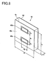
- FIG. 8 is a perspective view showing a structure of the remaining amount detection sensor according to the second embodiment of the present invention.
- FIG. 9 is a cross-sectional diagram of a side view of an arrangement state of the remaining amount detection sensor according to the second embodiment of the present invention.
- FIGS. 10A and 10B are graphs each schematically showing a relation between a liquid level position in a container and a capacitance of a detection electrode of the remaining amount detection sensor according to the second embodiment of the present invention.
- An axis of abscissa represents the liquid level position and an axis of ordinate represents the capacitance to be,detected.
- a remaining amount detection sensor 4A includes detection electrodes 40a and 40b in place of the detection electrode 4a of the remaining amount detection sensor 4 of the first embodiment, and a guard electrode 40c (second guard electrode) in place of the guard electrode 4b.
- the remaining amount detection sensor 4A is disposed outside the side surface of the main tank 9 in the ink-jet printer 100 of the first embodiment, and measures the capacitance on the main tank 9 side to detect whether a height of an ink liquid level 20b is within a predetermined range, thereby detecting the remaining amount of the ink 20 contained in the main tank 9.
- Thedetection electrodes 40a and 40b are rectangular conductive layers, each of which has a long side W 3 and a short side H 3 , and which are arranged in parallel with each other with a distance H 4 (note that 2 ⁇ H 3 +H 4 ⁇ H 1 and W 3 ⁇ W 1 ) and are provided on a surface to be brought into close contact with the remaining amount detection sensor 4A, thereby enabling detection of a potential via wiring (not shown).
- the short side of each of the detection electrodes 40a and 40b is placed along a height direction of an object whose remaining amount is to be detected of, for example, the main tank 9, that is, a vertical direction in which the ink liquid level 20b rises or falls (see FIG. 9 ).
- the guard electrode 40c is a conductive layer which is disposed in the same plane as the detection electrodes 40a and 40b so as to surround an outer periphery of each of the detection electrodes 40a and 40b, is extended to an outer edge of the remaining amount detection sensor 4A, that is, a rectangular outer shape with a size of W 1 xH 1 , and is grounded via wiring (not shown).
- capacitors having combined capacitances C a and C b , respectively.
- the capacitances C a and C b can be measured using an electrical circuit similar to the remaining amount detection circuit part 11 of the first embodiment.
- the remaining amount detection sensor 4A with the above-mentioned structure has the same structure as that in which the remaining amount detection sensors 4 of the first embodiment are arranged in parallel with each other in a vertical direction to be integrated with each other.
- the capacitance of the detection electrode 40a (40b) is affected only by the change of the dielectric body provided in the space formed on the sub-tank 3 side near the surface of the detection electrode 40a (40b) as shown in a region P a (P b ) indicated by the alternate long and two short dashes line of FIG. 9 .
- the capacitance of each of the detection electrodes 40a and 40b is changed as indicated by a curve 201 of FIG. 10A and a curve 202 of FIG. 10B .
- the capacitance of the detection electrode 40b is measured as a relatively small value C b 1 because the ink 20 does not enter the region P b .
- the capacitance is substantially linearly increased from C b 1 to C b 2 according to the height of the ink liquid level 20b.
- the ink liquid level 20b is equal to or higher than the height L4, the ink 20 is filled in the entire detection range of the detection electrode 40b, with the result that a constant value C b 2 is measured.
- the capacitance of the detection electrode 40a is substantially linearly increased from C a 1 to C a 2, and when the height is equal to or higher than the height L2, a constant value C a 2 is measured.
- a magnitude of the capacitance of each of the detection electrodes 40b and 40a is analyzed, thereby making it possible to detect the positional relation of the ink liquid level 20b with respect to the four heights L1, L2, L3, and L4 corresponding to the arrangement positions of the detection electrodes 40b and 40a in the height direction.
- the capacitances of the detection electrodes 40b and 40a are C b 1 and C a 2, respectively, it can be detected that the ink liquid level 20b is positioned between the heights L2 and L3.
- the height of the ink liquid level 20b can be measured.
- the remaining amount detection sensor 4A singly includes a plurality of detection electrodes. Accordingly, for example, the remaining amount detection sensor 4A can detect the ink liquid level 20b in the main tank 9, to thereby singly detect whether the remaining amount of the ink 20 contained in the main tank 9 is within the range of the predetermined amount with reliability. When the liquid level of the ink liquid level 20b is lower than the height L2, a reduction amount can be detected with accuracy. As a result, by the use of a detection output, an ink remaining amount can be displayed, and alarmdisplay for urging a user to replenish ink can be performed.
- FIG. 11 is an exploded perspective view showing arrangement of electrodes of the remaining amount detection sensor according to the third embodiment of the present invention.
- FIG. 12 is a cross-sectional diagram of a side view of a structure of the remaining amount detection sensor according to the third embodiment of the present invention.
- a remaining amount detection sensor 4B includes a guard electrode 41e (third guard electrode), a reference electrode 41a, and a dielectric layer 41b, in addition to a detection part 41A which is structured in the same manner as the remaining amount detection sensor 4 of the first embodiment.
- the guard electrode 41e is a conductive layer having the same shape and made of the same material as the guard electrode 4d, is disposed so as to face the guard electrode 4d on an opposite side of the detection electrode 4a, and is grounded via wiring (not shown).
- the dielectric layer 41b made of the same material as that of the dielectric layer 4c is disposed.
- the reference electrode 41a is formed of a conductive layer having an area smaller than that of each of the guard electrodes 4d and 41e, and is disposed in the dielectric layer 41b at an intermediate position in a direction in which the guard electrodes 4d and 41e are spaced apart, and at a substantial center between surface directions of the guard electrodes 4d and 41e, thereby making it possible to detect the potential via wiring (not shown).
- the area of the reference electrode 41a, the distance between the guard electrodes 4d and 41e, and the like are set so that the capacitance of the reference electrode 41a is set to the constant value C ref .
- the detection part 41A serving as a capacitor showing the capacitance C s corresponding to the peripheral dielectric body, and the reference part 41B serving as a capacitor having the constant capacitance C ref are integrated in layers.
- the remaining amount detection sensor 4B according to the third embodiment of the present invention can be formed of a multilayer printed board with the detection electrode 4a, the guard electrode 4b, and the guard electrodes 4d and 41e each being used as the electrode pattern.
- the dielectric layer 41b is formed of a base material of the multilayer printed board.
- the reference part 41B is integrated with the detection part 41A and serves as a capacitor made of the same material as that of the detection part 41A. Accordingly, the capacitance C ref can be formed in the same order as that of the capacitance C s of the detection part 41A merely by changing the area of the reference electrode 41a, the thickness of the dielectric layer 41b, and the like to a small extent in an analog manner.
- the reference part 41B thus set can be used in place of the reference capacitor 31 of the remaining amount detection circuit part 11 of the first embodiment.
- the reference part 41B is integrated with the detection part 41A and is made of the same material as that of the detection part 41A, the reference part 41B is to be changed in the same manner as the detection part 41A when the capacitance is changed due to a change in environmental conditions, for example, a change in temperature and humidity.
- a change in environmental conditions for example, a change in temperature and humidity.
- the remaining amount detection sensor 4 and the reference capacitor 31 which are made of different materials and have different structures, are individually changed in capacitance.
- a detection error of ⁇ C becomes larger than that in the case of using the remaining amount detection sensor 4B according to the third embodiment of the present invention.
- FIG. 13 is a perspective view schematically showing a general structure of a remaining amount detection sensor according to a modified example of the third embodiment of the present invention.
- a sensor part 42 having the same structure as that of the remaining amount detection sensor 4B according to the third embodiment is formed on a part of the multilayer printed board, and a remaining amount detection circuit part 43 (remaining amount detection circuit) is formed on the board on a side adjacent to the sensor part 42.
- the remaining amount detection circuit part 43 can employ a structure using the reference part 41B as the reference capacitor 31 in the remaining amount detection circuit part 11 according to the first embodiment.
- the remaining amount detection circuit part 43 is adjacent to and integrated with the sensor part 42.
- the wiring from each of the detection electrode 4a and the reference electrode 41a to the remaining amount detection circuit part 43 can be shortened and can be easily shielded by the use of the wiring pattern of the multilayer board, and signal degradation and noise contamination via the wiring can be reduced.
- the remaining amount detection circuit part 43 may be disposed at any position as long as the position does not affect the capacitance of the detection electrode 4a and the capacitance of the reference electrode 41a.
- the remaining amount detection circuit part 43 is formed on a substrate layer on an opposite side of the detection electrode 4a with respect to the guard electrode 4d on the lateral side of the sensor part 42.
- the effect of the electric field of the remaining amount detection circuit part 43 with respect to the detection electrode 4a can be blocked by the guard electrode 4d.
- the remaining amount detection sensor 4C according to the third embodiment is an example of a remaining amount detection sensor with a four-layered structure in which the guard electrode 4d is disposed on a rear side (opposite side of container) of the detection electrode 4a and the guard electrode 4b, and the reference electrode 41a and the guard electrode 41e are also disposed on the rear side thereof.
- the remaining amount detection sensor 4C is an example of a remaining amount detection sensor including the third guard electrode which is set to the same potential as that of each of the first and second guard electrodes and which is disposed so as to face the second guard electrode with a space on the opposite side of the container, and the reference electrode which is disposed so as to be sandwiched in the range in which the second guard electrode and the third electrode are opposed to each other.
- the reference electrode is integrally formed on the rear side of the detection part which is formed of the detection electrode and the first and second guard electrodes, whereby the reference electrode is integrated with the detection electrode so as to be set in substantially the same environmental conditions.
- the dielectric layer 41b is generally joined through a thin joining layer along the reference electrode 41a.
- the joining layer is omitted (similarly in cross-sectional diagram mentioned below).
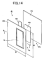
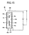
- FIG. 14 is an exploded perspective view showing arrangement of electrodes of the remaining amount detection sensor according to the fourth embodiment of the present invention.
- FIG. 15 is a cross-sectional diagram of the remaining amount detection sensor according to the fourth embodiment of the present invention taken along the line B-B of FIG. 14 .
- a remaining amount detection sensor 4D includes a guard electrode 44b (first guard electrode), a guard electrode 94d (second guard electrode), and a reference electrode 44e in place of the guard electrodes 4b and 4d and the reference electrode 41a of the remaining amount detection sensor 4C of the third embodiment.
- first guard electrode first guard electrode
- second guard electrode second guard electrode
- reference electrode 44e in place of the guard electrodes 4b and 4d and the reference electrode 41a of the remaining amount detection sensor 4C of the third embodiment.
- the guard electrode 44b is obtained by shifting an opening of the guard electrode 4b of the third embodiment in a short side direction of the detection electrode 4a, and has an outer shape with the same size as that of the guard electrode 4b.
- the guard electrode 44b is formed so as to surround the outer periphery of the detection electrode 9a in the same plane as the detection electrode 4a.
- the guard electrode 44d and the reference electrode 44e are disposed, respectively, through the dielectric layer 4c.
- the detection electrode 4a is disposed at a position apart from the center of the guard electrode 44b, and the guard electrode 44d is disposed on the rear side of the detection electrode 4a and disposed at least in a range covering the detection electrode 4a.
- the reference electrode 44e is formed in a rectangle shape extending in the same direction as the guard electrode 4b, and is formed with a size capable of being covered with the, guard electrode 44b. In addition, the reference electrode 44e is disposed on a lateral side of the guard electrode 44d in parallel with each other.
- the guard electrode 41e is disposed so as to face the reference electrode 44e in parallel with each other through the dielectric layer 41b.
- the guard electrode 41e also covers the entirety of the guard electrode 44d.
- the outer shape of the remaining amount detection sensor 4D is a rectangle shape with a size of W 1 xH 1 which can be contained within the range of the side surface of the sub-tank 3.
- the remaining amount detection sensor 4D is formed using a three-layered multilayer printed board.
- the detection electrode 4a and the guard electrode 44b are formed by a first layer conductive pattern
- the guard electrode 44d and the reference electrode 44e are formed by a second layer conductive pattern
- the guard electrode 41e is formed by a third layer conductive pattern (solid pattern).
- the dielectric layer 4c is formed of an insulating layer between the first layer conductive pattern and the second layer conductive pattern.
- the dielectric layer 41b is formed of an insulating layer between the second layer conductive pattern and the third layer conductive pattern.
- the structure of the remaining amount detection sensor 4D is not limited to the structure of a single multilayer printed board.
- the remaining amount detection sensor 4D may be structured by bonding a single-sided printed board and a double-sided printed board together with an adhesive to form a lamination structure having three conductive pattern layers.
- the guard electrodes 44b, 44d, and 41e are each grounded via wiring (not shown), and are each set to the same potential. As shown in FIG. 15 , between the detection electrode 4a and the guard electrode 44b, and between the detection electrode 4a and the guard electrode 44d, there are formed capacitors having the combined capacitance of C s . In addition, between the reference electrode 44e and the guard electrode 44b, and between the reference electrode 44e and the guardelectrode 41e, there are formed reference capacitors having the combined capacitance of C ref .
- Wiring connected to the detection electrode 4a, wiring connected to the reference electrode 44e, and a ground wire connected to each of the guard electrodes 44b, 44d, and 41e are each electrically connected to a remaining amount detection circuit (not shown) for detecting the capacitance of the detection electrode 4a to thereby detect the remaining amount in the sub-tank 3
- the area of the reference electrode 44e, the distance between the guard electrodes 44d and 41e, and the like are set so that the capacitance of the reference electrode 44e is set to the constant value C ref .
- the detection part 44A serving as a capacitor showing the capacitance C s corresponding to the peripheral dielectric body, and the reference part 44B serving as a capacitor having the constant capacitance C ref are formed in an integrated manner.
- the reference part 44B integrated with the detection part 44A serves as a capacitor made of the same material as that of the detection part 44A.
- the capacitance C ref can be formed in the same order as that of the capacitance C s of the detection part 44A merely by changing the area of the reference electrode 44e, the thicknesses of the dielectric layers 4c and 41b, and the like to a small extent in an analog manner.
- the reference part 44B thus set can be used in place of the reference capacitor 31 of the remaining amount detection circuit part 11 according to the first embodiment, and the same effects as those of the third embodiment can be obtained.
- the guard electrode 44d and the reference electrode 44e are formed in the same plane, in the case of forming the detection electrode 4a, the guard electrodes 44b, 44d, and 41e, and the reference electrode 44e by the conductive pattern of the multilayer printed board, the guard electrode 44d and the reference electrode 44e are formed by the conductive pattern in the same layer. As a result, the number of layers of the multilayer printed board can be reduced.
- the detection part 44A and the reference part 44B be disposed under substantially the same environmental conditions.
- the position of the reference electrode 44e in a width W 1 direction is preferably set to a position close to the detection electrode 4a to an extent that the reference electrode 44e is not affected by the capacitor formed of the detection electrode 4a and the guard electrode 44d.
- a length of the reference electrode 44e in a long side direction is preferably set to a length equivalent to that of the guard electrode 44b.
- the remaining amount detection sensor 4D is an example of a remaining amount detection sensor with a three-layered structure in which the guard electrode 44d is disposed on the rear side of the detection electrode 4a, and the reference electrode 44e is disposed so as to face the guard electrode 44b at a position in the same plane as the guard electrode 44d which is disposed on a side thereof.
- the remaining amount detection sensor 4D is an example of a remaining amount detection sensor including the third guard electrode which is set to the same potential as that of each of the first and second guard electrodes and which is disposed so as to face the first guard electrode with a space on the opposite side of the container, and the reference electrode which is disposed so as to be sandwiched in the range in which the first guard electrode and the third guard electrode are opposed to each other.
- the reference electrode is integrally formed on the lateral side of the detection part which is formed of the detection electrode and the first and second guard electrodes, whereby the reference electrode is integrated with the detection electrode so as to be set in substantially the same environmental conditions.
- FIG. 16 is an exploded perspective view showing arrangement of electrodes of the remaining amount detection sensor according to the fifth embodiment of the present invention.
- FIG. 17 is a cross-sectional diagram of the remaining amount detection sensor according to the fifth embodiment of the present invention taken along the line C-C of FIG. 16 .
- a remaining amount detection sensor 4E according to the fifth embodiment of the present invention is a generally widely-used four-layered printed board in which a sensor part 45A, which has the same structure as that of the fourth embodiment, and a remaining amount detection circuit part 45B are integrated with each other.
- the structure of the sensor part 45A is completely the same as that of the remaining amount detection sensor 4D according to the fourth embodiment, so a description thereof is omitted.
- the detection electrode 4a and the guard electrodes 44b, 44d, and 41e, and the reference electrode 44e of the sensor part 45A are formed by first to third layer conductive patterns of the four-layered printed board, and a fourth layer conductive pattern 45h is used for printed wiring for forming the detection circuit part 45B.
- a circuit part 45i is mounted in the conductive pattern 45h, and a side of the sensor part 45A and a side of the detection circuit part 45B are connected to each other via a through hole 45j or the like, for example, whereby the sensor part 45A and the detection circuit part 45B are laminated to be integrated with each other in substantially the same area range.
- FIG. 18 is an exploded perspective view showing arrangement of electrodes of the remaining amount detection sensor according to the sixth embodiment of the present invention.
- FIG. 19 is a cross-sectional diagram of the remaining amount detection sensor according to the sixth embodiment of the present invention taken along the line D-D of FIG. 18 .
- a remaining amount detection sensor 4 F according to the sixth embodiment of the present invention includes, in the remaining amount detection sensor 4D according to the fourth embodiment, a guard electrode 4b (first guard electrode) in place of the guard electrode 44b, and a pair of reference electrodes 46e in place of the reference electrode 44e.
- a guard electrode 4b first guard electrode
- a pair of reference electrodes 46e in place of the reference electrode 44e.
- the detection electrode 4a is disposed at the center of the guard electrode 4b in the width direction as in the first embodiment. Further, on the rear side (opposite side of container) of the detection electrode 4a, the guard electrode 44d is disposed through the dielectric layer 4c as in the fourth embodiment.
- the detection electrode 4a is disposed at the center of the guard electrode 4b, whereby the two reference electrodes 46e are disposed through the dielectric layer 4c in a range covered with the guard electrode 4b on the rear side of the guard electrode 4b in spaces formed on both lateral sides of the guard electrode 44d.
- the guard electrode 41e is disposed through the dielectric layer 41b.
- the reference electrodes 46e each have dimensions obtained by dividing into two the reference electrode 44e according to the fourth embodiment in the width direction, and are each set to the same potential via wiring (not shown).
- the guard electrodes 4b, 44d, and 41e are each grounded via wiring (not shown), and are each set to the same potential. As shown in FIG. 19 , between the detection electrode 4a and the guard electrode 4b, and between the detection electrode 4a and the guard electrode 44d, there are formed capacitors having the combined capacitance of C s . In addition, between the reference electrodes 46e and the guard electrode 4b, and between the reference electrodes 46e and the guard electrode 41e, there are formed reference capacitors having the combined capacitance of C ref .
- a detection part 46A having the same capacitance as that of the detection part 44A according to the fourth embodiment is formed, and reference parts 46B each serving as a reference capacitor having the same capacitance as that of the reference part 44B according to the fourth embodiment are formed on both lateral sides of the detection part 46A.
- the measurement as to the remaining amount detection can be performed in the same manner as in the fourth embodiment.
- the reference parts 46B are formed on both lateral sides of the detection part 46A, so the environmental conditions on the both lateral sides of the detection electrode 4a in a traverse direction affect each of the reference parts 46B in almost the same manner. As a result, even when the environmental conditions are different on both lateral sides of the detection part 46A, the effects on the detection accuracy of the remaining amount detection can be reduced. Accordingly, the remaining amount detection can be performed with high accuracy.
- FIG. 20 is an exploded perspective view showing arrangement of electrodes of the remaining amount detection sensor according to the seventh embodiment of the present invention.
- FIG. 21 is a cross-sectional diagram of the remaining amount detection sensor according to the seventh embodiment of the present invention taken along the line E-E of FIG. 20 .
- a remaining amount detection sensor 4G according to the seventh embodiment of the present invention includes a reference electrode 47e having a rectangular loop shape surrounding the outer periphery of the guard electrode 44d, in place of the pair of reference electrodes 46e of the remaining amount detection sensor 4F according to the sixth embodiment.
- a reference electrode 47e having a rectangular loop shape surrounding the outer periphery of the guard electrode 44d, in place of the pair of reference electrodes 46e of the remaining amount detection sensor 4F according to the sixth embodiment.
- the reference electrode 47e is formed so that the combined capacitance formed between the guard electrodes 4b and 41e opposed to each other is set to the same capacitance C ref as that of the pair of reference electrodes 46e according to the sixth embodiment.
- the reference part 47B is formed so as to surround the detection part 47A similar to the detection part 46A on the outer peripheral side.
- the measurement as to the remaining amount detection can be performed in the same manner as in the sixth embodiment.
- the reference part 47B surrounds the outer peripheral side of the detection part 47A, so the environmental conditions of the outer peripheral portion of the detection electrode 4a affect the reference parts 47B in almost the same manner.
- the effects on the detection accuracy of the remaining amount detection can be reduced. Accordingly, the remaining amount detection can be performed with high accuracy.
- the remaining amount detection sensor 4 may be used for detecting a remaining amount of ink contained in the main tank 9.
- the remaining amount detection sensor 4 may be formed of a multilayer printed board, or the remaining amount detection circuit part 11 may be formed on the same board.
- the reference capacitor 31 has a structure different from that of the remaining amount detection sensor 4, so the effects of the environmental fluctuation vary, but the wiring is shortened, thereby obtaining a remaining amount detection sensor resistant to noise.
- the remaining amount detection sensors 4D, 4E, 4F, and 4G according to the fourth to seventh embodiments, respectively can be used.
- the structures for arrangement of the electrodes of the remaining amount detection sensors can be applied also to the remaining amount detection sensor 4A according to the second embodiment.
- the remaining amount detection sensors 4D, 4E, 4F, and 4G are each formed by using the three-layered multilayer printed board so as to minimize the number of layers of the conductive patterns.
- the second guard electrode and the reference electrode are not necessarily formed in the same plane.
- each capacitance of the reference parts can be changed depending on a position of the second guard electrode and a difference in dielectric constant of the dielectric layer.
- the area of the second guard electrode or the like is appropriately set, thereby easily setting the combined capacitance to the C ref similar to that of the above embodiments.
- the remaining amount detection sensor is described as an example used for an ink-jet printer. This is only an example, and the remaining amount detection sensor may be used for detection of a remaining amount of content of a container for an apparatus used for every purpose as long as the remaining amount of the content of the container can be detected by a change in capacitance.
- the content of the container is a liquid
- the content is not limited to the liquid.
- the present invention may be used to detect a remaining amount of powder, for example.
Applications Claiming Priority (2)
| Application Number | Priority Date | Filing Date | Title |
|---|---|---|---|
| JP2007043651 | 2007-02-23 | ||
| JP2007313514A JP5133667B2 (ja) | 2007-02-23 | 2007-12-04 | 残量検知センサおよびそれを用いたインクジェットプリンタ |
Publications (3)
| Publication Number | Publication Date |
|---|---|
| EP1961575A2 true EP1961575A2 (de) | 2008-08-27 |
| EP1961575A3 EP1961575A3 (de) | 2009-07-22 |
| EP1961575B1 EP1961575B1 (de) | 2011-06-08 |
Family
ID=39495638
Family Applications (1)
| Application Number | Title | Priority Date | Filing Date |
|---|---|---|---|
| EP20080250608 Not-in-force EP1961575B1 (de) | 2007-02-23 | 2008-02-21 | Sensor zur Erkennung der verbleibenden Menge und Tintenstrahldrucker damit |
Country Status (1)
| Country | Link |
|---|---|
| EP (1) | EP1961575B1 (de) |
Cited By (12)
| Publication number | Priority date | Publication date | Assignee | Title |
|---|---|---|---|---|
| EP2400275A1 (de) * | 2010-06-25 | 2011-12-28 | Siemens Healthcare Diagnostics Products GmbH | Berührungslose Füllstandsmessung von Flüssigkeiten |
| EP2489996A1 (de) * | 2012-04-18 | 2012-08-22 | V-Zug AG | Haushaltgerät mit Wasserstandssensor |
| US8783802B2 (en) | 2009-02-28 | 2014-07-22 | Hewlett-Packard Development Company, L.P. | Intermediate fluid supply apparatus having flexible membrane |
| WO2014173925A1 (de) * | 2013-04-24 | 2014-10-30 | Skf Lubrication Systems Germany Ag | Füllstandsmessanordnung |
| WO2016053409A1 (en) * | 2014-10-01 | 2016-04-07 | Sealed Air Corporation | Fluid level sensor |
| CN106289444A (zh) * | 2015-06-02 | 2017-01-04 | 大日科技股份有限公司 | 物料检测装置 |
| WO2018017851A1 (en) | 2016-07-21 | 2018-01-25 | Touchsensor Technologies, Llc | Capacitive continuous fluid level sensor |
| CN109318590A (zh) * | 2017-07-31 | 2019-02-12 | 兄弟工业株式会社 | 图像记录装置 |
| CN112484810A (zh) * | 2020-12-02 | 2021-03-12 | 上海钛米机器人股份有限公司 | 一种溶液检测装置及方法 |
| DE102019129793A1 (de) * | 2019-11-05 | 2021-05-06 | Fette Compacting Gmbh | Vorrichtung zum kapazitiven Messen des Pulverfüllstands in einer Fülleinrichtung einer Rundläuferpresse |
| US20210372842A1 (en) * | 2020-06-02 | 2021-12-02 | Microchip Technology Incorporated | Capacitive sensing utilizing a differential value indication |
| EP4306914A1 (de) * | 2022-07-14 | 2024-01-17 | Illinois Tool Works Inc. | Kapazitiver sensor zur erfassung eines fluidniveaus in einem beweglichen fluidtank eines haushaltsgeräts |
Citations (2)
| Publication number | Priority date | Publication date | Assignee | Title |
|---|---|---|---|---|
| JPH08197749A (ja) | 1995-01-31 | 1996-08-06 | Matsushita Electric Ind Co Ltd | インクジェットプリンタ装置 |
| JPH09166474A (ja) | 1995-12-19 | 1997-06-24 | Omron Corp | 残量センサ |
Family Cites Families (3)
| Publication number | Priority date | Publication date | Assignee | Title |
|---|---|---|---|---|
| US3706980A (en) * | 1970-04-27 | 1972-12-19 | Drexelbrook Controls | Rf system for measuring the level of materials |
| US4757252A (en) * | 1985-10-25 | 1988-07-12 | Drexelbrook Controls, Inc. | Probe system for measuring the condition of materials |
| US4749988A (en) * | 1986-11-20 | 1988-06-07 | Imtec Products, Inc. | Non-invasive liquid level sensor |
-
2008
- 2008-02-21 EP EP20080250608 patent/EP1961575B1/de not_active Not-in-force
Patent Citations (2)
| Publication number | Priority date | Publication date | Assignee | Title |
|---|---|---|---|---|
| JPH08197749A (ja) | 1995-01-31 | 1996-08-06 | Matsushita Electric Ind Co Ltd | インクジェットプリンタ装置 |
| JPH09166474A (ja) | 1995-12-19 | 1997-06-24 | Omron Corp | 残量センサ |
Cited By (20)
| Publication number | Priority date | Publication date | Assignee | Title |
|---|---|---|---|---|
| US8783802B2 (en) | 2009-02-28 | 2014-07-22 | Hewlett-Packard Development Company, L.P. | Intermediate fluid supply apparatus having flexible membrane |
| EP2400275A1 (de) * | 2010-06-25 | 2011-12-28 | Siemens Healthcare Diagnostics Products GmbH | Berührungslose Füllstandsmessung von Flüssigkeiten |
| EP2489996A1 (de) * | 2012-04-18 | 2012-08-22 | V-Zug AG | Haushaltgerät mit Wasserstandssensor |
| WO2014173925A1 (de) * | 2013-04-24 | 2014-10-30 | Skf Lubrication Systems Germany Ag | Füllstandsmessanordnung |
| CN105229429A (zh) * | 2013-04-24 | 2016-01-06 | 德国斯凯孚润滑油系统有限责任公司 | 液位测量装置 |
| US9733116B2 (en) | 2013-04-24 | 2017-08-15 | Skf Lubrication Systems Germany Gmbh | Fill level measurement system |
| CN105229429B (zh) * | 2013-04-24 | 2019-06-28 | 德国斯凯孚润滑油系统有限责任公司 | 液位测量装置 |
| WO2016053409A1 (en) * | 2014-10-01 | 2016-04-07 | Sealed Air Corporation | Fluid level sensor |
| US9476752B2 (en) | 2014-10-01 | 2016-10-25 | Sealed Air Corporation | Fluid level sensor |
| CN106289444A (zh) * | 2015-06-02 | 2017-01-04 | 大日科技股份有限公司 | 物料检测装置 |
| EP3487628A4 (de) * | 2016-07-21 | 2020-02-26 | TouchSensor Technologies, LLC | Kapazitiver kontinuierlicher flüssigkeitsstandssensor |
| WO2018017851A1 (en) | 2016-07-21 | 2018-01-25 | Touchsensor Technologies, Llc | Capacitive continuous fluid level sensor |
| CN109318590A (zh) * | 2017-07-31 | 2019-02-12 | 兄弟工业株式会社 | 图像记录装置 |
| CN109318590B (zh) * | 2017-07-31 | 2021-06-04 | 兄弟工业株式会社 | 图像记录装置 |
| DE102019129793A1 (de) * | 2019-11-05 | 2021-05-06 | Fette Compacting Gmbh | Vorrichtung zum kapazitiven Messen des Pulverfüllstands in einer Fülleinrichtung einer Rundläuferpresse |
| US20210372842A1 (en) * | 2020-06-02 | 2021-12-02 | Microchip Technology Incorporated | Capacitive sensing utilizing a differential value indication |
| WO2021247602A1 (en) * | 2020-06-02 | 2021-12-09 | Microchip Technology Incorporated | Capacitive sensing utilizing a differential value indication |
| US11860022B2 (en) * | 2020-06-02 | 2024-01-02 | Microchip Technology, Inc. | Capacitive sensing utilizing a differential value indication |
| CN112484810A (zh) * | 2020-12-02 | 2021-03-12 | 上海钛米机器人股份有限公司 | 一种溶液检测装置及方法 |
| EP4306914A1 (de) * | 2022-07-14 | 2024-01-17 | Illinois Tool Works Inc. | Kapazitiver sensor zur erfassung eines fluidniveaus in einem beweglichen fluidtank eines haushaltsgeräts |
Also Published As
| Publication number | Publication date |
|---|---|
| EP1961575A3 (de) | 2009-07-22 |
| EP1961575B1 (de) | 2011-06-08 |
Similar Documents
| Publication | Publication Date | Title |
|---|---|---|
| US7798586B2 (en) | Remaining amount detection sensor and ink-jet printer using the same | |
| EP1961575B1 (de) | Sensor zur Erkennung der verbleibenden Menge und Tintenstrahldrucker damit | |
| US7866801B2 (en) | Liquid-supplying system and liquid-consuming apparatus | |
| JP4286340B2 (ja) | インクレベル感知システム | |
| KR100546494B1 (ko) | 잉크젯인쇄시스템용잉크저장용기및그안에잔류하는잉크량결정방법 | |
| KR20070094491A (ko) | 액적 토출 헤드, 및 액적 토출 장치 | |
| GB2312283A (en) | Inductive ink level detection mechanism | |
| US20070008365A1 (en) | Ink cartridge including a unit to sense a remaining amount of ink | |
| US7509868B2 (en) | Liquid detecting device, liquid container, and liquid refilling method | |
| US10752010B2 (en) | Liquid ejection apparatus | |
| KR100694133B1 (ko) | 잉크젯 프린터의 잉크 레벨 검지장치 | |
| US8841926B2 (en) | Method, liquid supply unit, and measurement device for a level indicator | |
| JPH02169259A (ja) | インク残量検知装置 | |
| EP1457340B1 (de) | Tintensack und Vorrichtung zur Tintenerfassung | |
| EP2055488A1 (de) | Flüssigkeitsbehälter und flüssigkeit verbrauchende vorrichtung | |
| KR100687919B1 (ko) | 프린팅 장치 | |
| JP2931079B2 (ja) | 記録装置用インク検出装置 | |
| US20230158799A1 (en) | Storage device and liquid ejection apparatus | |
| US20230158803A1 (en) | Storage device and liquid ejection apparatus | |
| JPS5975122A (ja) | インクジエツト記録装置におけるインク残量検知方法 | |
| US20230158804A1 (en) | Storage device and liquid ejection apparatus | |
| US11485145B2 (en) | Physical quantity detection device and printing apparatus | |
| KR100694150B1 (ko) | 잉크젯 프린터의 잉크 레벨 검지 장치 | |
| JP2009241585A (ja) | 液体検出装置及びそれを用いた液体収容容器 | |
| JPH02107452A (ja) | インク残量検出装置 |
Legal Events
| Date | Code | Title | Description |
|---|---|---|---|
| PUAI | Public reference made under article 153(3) epc to a published international application that has entered the european phase |
Free format text: ORIGINAL CODE: 0009012 |
|
| AK | Designated contracting states |
Kind code of ref document: A2 Designated state(s): AT BE BG CH CY CZ DE DK EE ES FI FR GB GR HR HU IE IS IT LI LT LU LV MC MT NL NO PL PT RO SE SI SK TR |
|
| AX | Request for extension of the european patent |
Extension state: AL BA MK RS |
|
| PUAL | Search report despatched |
Free format text: ORIGINAL CODE: 0009013 |
|
| AK | Designated contracting states |
Kind code of ref document: A3 Designated state(s): AT BE BG CH CY CZ DE DK EE ES FI FR GB GR HR HU IE IS IT LI LT LU LV MC MT NL NO PL PT RO SE SI SK TR |
|
| AX | Request for extension of the european patent |
Extension state: AL BA MK RS |
|
| 17P | Request for examination filed |
Effective date: 20100122 |
|
| AKX | Designation fees paid |
Designated state(s): DE ES FR GB NL |
|
| GRAP | Despatch of communication of intention to grant a patent |
Free format text: ORIGINAL CODE: EPIDOSNIGR1 |
|
| GRAS | Grant fee paid |
Free format text: ORIGINAL CODE: EPIDOSNIGR3 |
|
| GRAA | (expected) grant |
Free format text: ORIGINAL CODE: 0009210 |
|
| AK | Designated contracting states |
Kind code of ref document: B1 Designated state(s): DE ES FR GB NL |
|
| REG | Reference to a national code |
Ref country code: GB Ref legal event code: FG4D |
|
| REG | Reference to a national code |
Ref country code: DE Ref legal event code: R096 Ref document number: 602008007383 Country of ref document: DE Effective date: 20110721 |
|
| REG | Reference to a national code |
Ref country code: NL Ref legal event code: VDEP Effective date: 20110608 |
|
| PG25 | Lapsed in a contracting state [announced via postgrant information from national office to epo] |
Ref country code: ES Free format text: LAPSE BECAUSE OF FAILURE TO SUBMIT A TRANSLATION OF THE DESCRIPTION OR TO PAY THE FEE WITHIN THE PRESCRIBED TIME-LIMIT Effective date: 20110919 |
|
| PG25 | Lapsed in a contracting state [announced via postgrant information from national office to epo] |
Ref country code: NL Free format text: LAPSE BECAUSE OF FAILURE TO SUBMIT A TRANSLATION OF THE DESCRIPTION OR TO PAY THE FEE WITHIN THE PRESCRIBED TIME-LIMIT Effective date: 20110608 |
|
| PLBE | No opposition filed within time limit |
Free format text: ORIGINAL CODE: 0009261 |
|
| STAA | Information on the status of an ep patent application or granted ep patent |
Free format text: STATUS: NO OPPOSITION FILED WITHIN TIME LIMIT |
|
| 26N | No opposition filed |
Effective date: 20120309 |
|
| REG | Reference to a national code |
Ref country code: DE Ref legal event code: R097 Ref document number: 602008007383 Country of ref document: DE Effective date: 20120309 |
|
| REG | Reference to a national code |
Ref country code: FR Ref legal event code: PLFP Year of fee payment: 9 |
|
| REG | Reference to a national code |
Ref country code: FR Ref legal event code: PLFP Year of fee payment: 10 |
|
| REG | Reference to a national code |
Ref country code: FR Ref legal event code: PLFP Year of fee payment: 11 |
|
| PGFP | Annual fee paid to national office [announced via postgrant information from national office to epo] |
Ref country code: DE Payment date: 20190205 Year of fee payment: 12 Ref country code: FR Payment date: 20190111 Year of fee payment: 12 Ref country code: GB Payment date: 20190220 Year of fee payment: 12 |
|
| REG | Reference to a national code |
Ref country code: DE Ref legal event code: R119 Ref document number: 602008007383 Country of ref document: DE |
|
| GBPC | Gb: european patent ceased through non-payment of renewal fee |
Effective date: 20200221 |
|
| PG25 | Lapsed in a contracting state [announced via postgrant information from national office to epo] |
Ref country code: GB Free format text: LAPSE BECAUSE OF NON-PAYMENT OF DUE FEES Effective date: 20200221 Ref country code: FR Free format text: LAPSE BECAUSE OF NON-PAYMENT OF DUE FEES Effective date: 20200229 Ref country code: DE Free format text: LAPSE BECAUSE OF NON-PAYMENT OF DUE FEES Effective date: 20200901 |