EP1961378A1 - Einstellungsobligatorische mechanische Ventilationsparameter basierend auf der Patientenphysiologie - Google Patents
Einstellungsobligatorische mechanische Ventilationsparameter basierend auf der Patientenphysiologie Download PDFInfo
- Publication number
- EP1961378A1 EP1961378A1 EP08101753A EP08101753A EP1961378A1 EP 1961378 A1 EP1961378 A1 EP 1961378A1 EP 08101753 A EP08101753 A EP 08101753A EP 08101753 A EP08101753 A EP 08101753A EP 1961378 A1 EP1961378 A1 EP 1961378A1
- Authority
- EP
- European Patent Office
- Prior art keywords
- patient
- time
- subject
- expiratory
- ventilator
- Prior art date
- Legal status (The legal status is an assumption and is not a legal conclusion. Google has not performed a legal analysis and makes no representation as to the accuracy of the status listed.)
- Withdrawn
Links
Images


Classifications
-
- A—HUMAN NECESSITIES
- A61—MEDICAL OR VETERINARY SCIENCE; HYGIENE
- A61M—DEVICES FOR INTRODUCING MEDIA INTO, OR ONTO, THE BODY; DEVICES FOR TRANSDUCING BODY MEDIA OR FOR TAKING MEDIA FROM THE BODY; DEVICES FOR PRODUCING OR ENDING SLEEP OR STUPOR
- A61M16/00—Devices for influencing the respiratory system of patients by gas treatment, e.g. mouth-to-mouth respiration; Tracheal tubes
- A61M16/021—Devices for influencing the respiratory system of patients by gas treatment, e.g. mouth-to-mouth respiration; Tracheal tubes operated by electrical means
- A61M16/022—Control means therefor
- A61M16/024—Control means therefor including calculation means, e.g. using a processor
-
- A—HUMAN NECESSITIES
- A61—MEDICAL OR VETERINARY SCIENCE; HYGIENE
- A61M—DEVICES FOR INTRODUCING MEDIA INTO, OR ONTO, THE BODY; DEVICES FOR TRANSDUCING BODY MEDIA OR FOR TAKING MEDIA FROM THE BODY; DEVICES FOR PRODUCING OR ENDING SLEEP OR STUPOR
- A61M16/00—Devices for influencing the respiratory system of patients by gas treatment, e.g. mouth-to-mouth respiration; Tracheal tubes
- A61M16/0003—Accessories therefor, e.g. sensors, vibrators, negative pressure
- A61M2016/003—Accessories therefor, e.g. sensors, vibrators, negative pressure with a flowmeter
- A61M2016/0033—Accessories therefor, e.g. sensors, vibrators, negative pressure with a flowmeter electrical
- A61M2016/0036—Accessories therefor, e.g. sensors, vibrators, negative pressure with a flowmeter electrical in the breathing tube and used in both inspiratory and expiratory phase
-
- A—HUMAN NECESSITIES
- A61—MEDICAL OR VETERINARY SCIENCE; HYGIENE
- A61M—DEVICES FOR INTRODUCING MEDIA INTO, OR ONTO, THE BODY; DEVICES FOR TRANSDUCING BODY MEDIA OR FOR TAKING MEDIA FROM THE BODY; DEVICES FOR PRODUCING OR ENDING SLEEP OR STUPOR
- A61M2205/00—General characteristics of the apparatus
- A61M2205/33—Controlling, regulating or measuring
- A61M2205/3327—Measuring
-
- A—HUMAN NECESSITIES
- A61—MEDICAL OR VETERINARY SCIENCE; HYGIENE
- A61M—DEVICES FOR INTRODUCING MEDIA INTO, OR ONTO, THE BODY; DEVICES FOR TRANSDUCING BODY MEDIA OR FOR TAKING MEDIA FROM THE BODY; DEVICES FOR PRODUCING OR ENDING SLEEP OR STUPOR
- A61M2205/00—General characteristics of the apparatus
- A61M2205/33—Controlling, regulating or measuring
- A61M2205/3331—Pressure; Flow
-
- A—HUMAN NECESSITIES
- A61—MEDICAL OR VETERINARY SCIENCE; HYGIENE
- A61M—DEVICES FOR INTRODUCING MEDIA INTO, OR ONTO, THE BODY; DEVICES FOR TRANSDUCING BODY MEDIA OR FOR TAKING MEDIA FROM THE BODY; DEVICES FOR PRODUCING OR ENDING SLEEP OR STUPOR
- A61M2205/00—General characteristics of the apparatus
- A61M2205/33—Controlling, regulating or measuring
- A61M2205/3368—Temperature
-
- A—HUMAN NECESSITIES
- A61—MEDICAL OR VETERINARY SCIENCE; HYGIENE
- A61M—DEVICES FOR INTRODUCING MEDIA INTO, OR ONTO, THE BODY; DEVICES FOR TRANSDUCING BODY MEDIA OR FOR TAKING MEDIA FROM THE BODY; DEVICES FOR PRODUCING OR ENDING SLEEP OR STUPOR
- A61M2205/00—General characteristics of the apparatus
- A61M2205/33—Controlling, regulating or measuring
- A61M2205/3375—Acoustical, e.g. ultrasonic, measuring means
-
- A—HUMAN NECESSITIES
- A61—MEDICAL OR VETERINARY SCIENCE; HYGIENE
- A61M—DEVICES FOR INTRODUCING MEDIA INTO, OR ONTO, THE BODY; DEVICES FOR TRANSDUCING BODY MEDIA OR FOR TAKING MEDIA FROM THE BODY; DEVICES FOR PRODUCING OR ENDING SLEEP OR STUPOR
- A61M2205/00—General characteristics of the apparatus
- A61M2205/50—General characteristics of the apparatus with microprocessors or computers
- A61M2205/502—User interfaces, e.g. screens or keyboards
Definitions
- inventive arrangements relate to respiratory care, and more specifically, to improvements in controlling mandatory mechanical ventilation.
- modem ventilators usually include electronic and pneumatic control systems that control the pressure, flow rates, and/or volume of gases delivered to, and extracted from, patients needing medical respiratory assistance.
- control systems include a variety of knobs, dials, switches, and the like, for interfacing with treating clinicians, who support the patient's breathing by adjusting the afore-mentioned pressure, flow rates, and/or volume of the patient's pulmonary gas exchanges, particularly as the condition and/or status of the patient changes.
- Such parameter adjustments although highly desirable, remain challenging to control accurately, particularly using present-day arrangements and practices.
- ventilation is a complex process of delivering oxygen to, and removing carbon dioxide from, alveoli within patients' lungs.
- a patient whenever a patient is ventilated, that patient becomes part of a complex, interactive system that is expected to promote adequate ventilation and gas exchange on behalf of the patient, eventually leading to the patient's stabilization, recovery, and ultimate ability to return to breathing normally and independently.
- CMV controlled mechanical ventilation
- ventilator support should be individually tailored for each patient's existing pathophysiology, rather than deploying a generalized approach for all patients with potentially disparate ventilation needs.
- a method of setting expiratory time in controlled mechanical ventilation comprises setting a subject's expiratory time based on the subject's natural exhalation time, when the subject's natural exhalation flow ceases, and/or when the subject's tidal volume is expired.
- a method of setting expiratory time in controlled mechanical ventilation comprises determining a subject's natural exhalation time, when the subject's natural exhalation flow ceases, and/or when said subject's tidal volume is expired, and setting the subject's expiratory time based on the determination.
- a device for use in controlled mechanical ventilation comprises a flow rate sensor configured to determine a subject's natural exhalation time, when the subject's natural exhalation flow ceases, and/or when the subject's tidal volume is expired, and base the subject's expiratory time on the determination.
- FIG. 1 depicts a front perspective view of a medical system comprising a ventilator
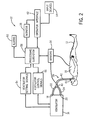
- FIG. 2 depicts a block diagram of a medical system providing ventilator support to a patient
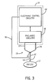
- FIG. 3 depicts a block diagram of a ventilator providing ventilator support to the patient
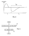
- FIG. 4 depicts a flow diagram of the patient's inspiratory time (T I ), expiratory time (T E ), and natural exhalation time (T EXH ) for a single breath, particularly during controlled mechanical ventilation (CMV);
- T I inspiratory time
- T E expiratory time
- T EXH natural exhalation time
- FIG. 5 depicts a flowchart of a simplified arrangement for setting the patient's expiratory time (T E ) based on the patient's natural exhalation time (T EXH );
- FIG. 6 depicts a flowchart of a simplified arrangement for setting the patient's expiratory time (T E ) based on when the patient's natural exhalation flow ceases;
- FIG. 7 depicts a flowchart of a simplified arrangement for setting the patient's expiratory time (T E ) based on when the patient's tidal volume has expired;
- FIG. 8 depicts a response curve of the patient's delivered inspiratory time (dT I ) and exhaled CO 2 levels (F ET CO 2 );
- FIG. 9 depicts the delivered inspiratory time (dT I ) response curve of FIG. 8 , graphically depicting an arrangement to identify the patient's optimal inspiratory time (T I-OPTIMAL );
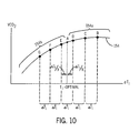
- FIG. 10 depicts a response curve of the patient's delivered inspiratory time (dT I ) and exhaled VCO 2 levels.
- anesthesia machine 14 includes a ventilator 16, the latter having suitable connectors 18, 20 for connecting to an inspiratory branch 22 and expiratory branch 24 of a breathing circuit 26 leading to the patient 12.
- the ventilator 16 and breathing circuit 26 cooperate to provide breathing gases to the patient 12 via the inspiratory branch 22 and to receive gases expired by the patient 12 via the expiratory branch 24.
- the ventilator 16 can also be provided with a bag 28 for manually bagging the patient 12. More specifically, the bag 28 can be filled with breathing gases and manually squeezed by a clinician (not shown) to provide appropriate breathing gases to the patient 12. Using this bag 28, or "bagging the patient,” is often required and/or preferred by the clinicians, as it can enable them to manually and/or immediately control delivery of the breathing gases to the patient 12. Equally important, the clinician can sense conditions in the respiration and/or lungs 30 of the patient 12 according to the feel of the bag 28, and then accommodate for the same. While it can be difficult to accurately obtain this feedback while mechanically ventilating the patient 12 using the ventilator 16, it can also fatigue the clinician if the clinician is forced to bag the patient 12 for too long a period of time. Thus, the ventilator 16 can also provide a toggle 32 for switching and/or alternating between manual and automated ventilation.
- the ventilator 16 can also receive inputs from sensors 34 associated with the patient 12 and/or ventilator 16 at a processing terminal 36 for subsequent processing thereof, and which can be displayed on a monitor 38, which can be provided by the medical system 10 and/or the like.
- Representative data received from the sensors 34 can include, for example, inspiratory time (T I ), expiratory time (T E ), natural exhalation time (T EXH ), respiratory rates ( f ), I:E ratios, positive end expiratory pressure (PEEP), fractional inspired oxygen (F I O 2 ), fractional expired oxygen (F E O 2 ), breathing gas flow (F), tidal volumes (V T ), temperatures (T), airway pressures (P aw ), arterial blood oxygen saturation levels (S a O 2 ), blood pressure information (BP), pulse rates (PR), pulse oximetry levels (S p O 2 ), exhaled CO 2 levels (F ET CO 2 ), concentration of inspired inhalation anesthetic agent (C I agent), concentration of expired inhalation anesthetic agent (C E agent), arterial blood oxygen partial pressure (P a O 2 ), arterial carbon dioxide partial pressure (P a CO 2 ), and the like.
- PEEP positive end expiratory pressure
- F I O 2 fractional inspired oxygen
- the ventilator 16 provides breathing gases to the patient 12 via the breathing circuit 26.
- the breathing circuit 26 typically includes the afore-mentioned inspiratory branch 22 and expiratory branch 24.
- one end of each of the inspiratory branch 22 and expiratory branch 24 is connected to the ventilator 16, while the other ends thereof are usually connected to a Y-connector 40, which can then connect to the patient 12 through a patient branch 42, which can also include an interface 43 to secure the patient's 12 airways to the breathing circuit 26 and/or prevent gas leakage out thereof.
- the ventilator 16 can also include electronic control circuitry 44 and/or pneumatic circuitry 46. More specifically, various pneumatic elements of the pneumatic circuitry 46 provide breathing gases to the lungs 30 of the patient 12 through the inspiratory branch 22 of the breathing circuit 26 during inhalation. Upon exhalation, the breathing gases are discharged from the lungs 30 of the patient 12 and into the expiratory branch 24 of the breathing circuit 26.
- This process can be iteratively enabled by the electronic control circuitry 44 and/or pneumatic circuitry 46 in the ventilator 16, which can establish various control parameters, such as the number of breaths per minute to administer to the patient 12, tidal volumes (V T ), maximum pressures, etc., that can characterize the mechanical ventilation that the ventilator 16 supplies to the patient 12.
- the ventilator 16 may be microprocessor based and operable in conjunction with a suitable memory to control the pulmonary gas exchanges in the breathing circuit 26 connected to, and between, the patient 12 and ventilator 16.
- the various pneumatic elements of the pneumatic circuitry 46 usually comprise a source of pressurized gas (not shown), which can operate through a gas concentration subsystem (not shown) to provide the breathing gases to the lungs 30 of the patient 12.
- This pneumatic circuitry 46 may provide the breathing gases directly to the lungs 30 of the patient 12, as typical in a chronic and/or critical care application, or it may provide a driving gas to compress a bellows 48 (see FIG. 1 ) containing the breathing gases, which can, in turn, supply the breathing gases to the lungs 30 of the patient 12, as typical in an anesthesia application.
- the breathing gases iteratively pass from the inspiratory branch 22 to the Y-connector 40 and to the patient 12, and then back to the ventilator 16 via the Y-connector 40 and expiratory branch 24.
- one or more of the sensors 34, placed in the breathing circuit 26, can also provide feedback signals back to the electronic control circuitry 44 of the ventilator 16, particularly via a feedback loop 52. More specifically, a signal in the feedback loop 52 could be proportional, for example, to gas flows and/or airway pressures in the patient branch 42 leading to the lungs 30 of the patient 12.
- Inhaled and exhaled gas concentrations are also representative feedback signals that could be captured by the sensors 34, as can the time periods between when the ventilator 16 permits the patient 12 to inhale and exhale, as well as when the patient's 12 natural inspiratory and expiratory flows cease.
- the electronic control circuitry 44 of the ventilator 16 can also control displaying numerical and/or graphical information from the breathing circuit 26 on the monitor 38 of the medical system 10 (see FIG. 1 ), as well as other patient 12 and/or system 10 parameters from other sensors 34 and/or the processing terminal 36 (see FIG. 1 ).
- various components of which can also be integrated and/or separated, as needed and/or desired.
- the electronic control circuitry 44 can also coordinate and/or control, among other things, for example, other ventilator setting signals 54, ventilator control signals 56, and/or a processing subsystem 58, such as for receiving and processing signals, such as from the sensors 34, display signals for the monitor 38 and/or the like, alarms 60, and/or an operator interface 62, which can include one or more input devices 64, etc., all as needed and/or desired and interconnected appropriately (e.g., see FIG. 2 ).
- These components are functionally depicted for clarity, wherein various ones thereof can also be integrated and/or separated, as needed and/or desired.
- other functional components should also be well-understood but are not shown - e.g., one or more power supplies for the medical system 10 and/or anesthesia machine 14 and/or ventilator 16, etc. (not shown).
- T I is inspiratory time.
- T I is the amount of time, measured in seconds, set on the ventilator 16 by the clinician, lasting from the beginning of the patient's 12 inspiration to the beginning of the patient's 12 expiration. Accordingly, T I is the patient's 12 inspiratory time.
- Inspiratory times T I can be further broken down into a set inspiratory time sT I , a delivered inspiratory time dT I , and a measured inspiratory time mT I .
- the set inspiratory time sT I is the amount of time that the clinician sets on the ventilator 16 to deliver gases to the patient 12 during inspiration
- the delivered inspiratory time dT I is the amount of time that gases are actually allowed to be delivered to the patient 12 from the ventilator 16 during inspiration
- the measured inspiratory time mT I is the amount of time that the ventilator 16 measures for allowing gases to be delivered to the patient 12 during inspiration.
- the set inspiratory time sT I , delivered inspiratory time dT I , and measured inspiratory time mT I are equal or substantially equal.
- each of these inspiratory times T I may be different or slightly different.
- the clinician and/or ventilator 16 may have established a set inspiratory time sT I , yet the delivered inspiratory time dT I may deviate therefrom in the process of searching for, for example, the patient's 12 optimal inspiratory time T I-OPTIMAL.
- T E expiratory time
- T E is the amount of time, measured in seconds, set on the ventilator 16 by the clinician, lasting from the beginning of the patient's 12 expiration to the beginning of the patient's 12 inspiration. Accordingly, T E is the patient's 12 expiratory time.
- expiratory times T E can also be further broken down into a set expiratory time sT E , a delivered expiratory time dT E , and a measured expiratory time mT E .
- the set expiratory time sT E is the amount of time that the clinician sets on the ventilator 16 to allow the patient 12 to exhale gases during expiration
- the delivered expiratory time dT E is the amount of time that gases are allowed to be exhaled by the patient 12 during expiration
- the measured expiratory time mT E is the amount of time that the ventilator 16 measures for having allowed the patient 12 to exhale gases during expiration.
- the set expiratory time sT E , delivered expiratory time dT E , and measured expiratory time mT E are equal or substantially equal.
- each of these expiratory times T E may be different or slightly different.
- the clinician and/or ventilator 16 may have established a set expiratory time sT E , yet the delivered expiratory time dT E may deviate therefrom in the process of searching, for example, for the patient's 12 natural exhalation time T EXH .
- I:E ratios are ratios between T I and T E .
- I:E ratios measure inspiratory times divided by expiratory times - i.e., T I / T E , which is commonly expressed as a ratio.
- Common I:E ratios are 1:2, meaning patients 12 may inhale for a certain period of time (x) and then exhale for twice as long (2x).
- I:E ratios can also be set at ratios closer to 1:3 and/or 1:4, particularly to provide the necessary expiratory time T E for a given patient 12 to fully exhale, although I:E ratios from 1:8 and 2:1 are also not uncommon, with common ventilators 16 providing 0.5 gradations therebetween.
- COPD chronic obstructive pulmonary disease
- T EXH is natural exhalation time.
- T EXH is the amount of time, measured in seconds, required for the patient's 12 natural exhalation flow to cease. Accordingly, T EXH is the patient's 12 natural exhalation time.
- the patient's 12 expiratory time T E does not equal the patient's 12 natural exhalation time T EXH - i.e., the patient's 12 expiratory time T E , as set by the clinician on the ventilator 16, often does not coincide with the patient's 12 natural exhalation time T EXH .
- respiratory rates f are commonly set between 6 - 10 breaths/minute and I:E ratios are commonly set at 1:2, resulting in many clinicians setting expiratory times T E between 4.0 - 6.6 seconds, as opposed to typical natural exhalation times T EXH being less than or equal to approximately 0.8 - 1.5 seconds.
- T E the patient's 12 expiratory times T E approximately equal to the patient's 12 natural exhalation times T EXH (i.e., 2 * T EHX ⁇ TE ⁇ T EXH ).
- the clinician or ventilator 16 sets the patient's 12 expiratory time T E less than or equal to the patient's 12 natural exhalation time T EXH , there can be inadequate time for the patient 12 to expel the gases in the patient's 12 lungs 30. This can result in stacking breaths in the patient's 12 lungs 30 (i.e., so-called "breath stacking"), thereby inadvertently and/or unknowingly elevating the patient's 12 lung pressure.
- the inventive arrangements set the patient's 12 expiratory time T E approximately equal to the patient's 12 natural exhalation time T EXH , preferably with the patient's 12 expiratory time T E being set greater than or equal to the patient's 12 natural exhalation time T EXH .
- PEEP positive end expiratory pressure
- PEEP is the patient's 12 positive end expiratory pressure, often measured in cmH 2 O. Accordingly, PEEP is the amount of pressure in the patient's 12 lungs 30 at the end of the patient's 12 expiratory time T E , as controlled by the ventilator 16.
- positive end expiratory pressure PEEP can also be further broken down into a set positive end expiratory pressure sPEEP, a measured positive end expiratory pressure mPEEP, and a delivered positive end expiratory pressure dPEEP.
- the set positive end expiratory pressure sPEEP is the amount of pressure that the clinician sets on the ventilator 16 for the patient 12
- the measured positive end expiratory pressure mPEEP is the amount of pressure in the patient's 12 lungs 30 at the end of the patient's 12 expiratory time T E
- the delivered positive end expiratory pressure dPEEP is the amount of pressure delivered by the ventilator to the patient 12.
- the set positive end expiratory pressure sPEEP, measured positive end expiratory pressure mPEEP, and delivered positive end expiratory pressure dPEEP are equal or substantially equal.
- the measured positive end expiratory pressure mPEEP can be greater than the set positive end expiratory pressure sPEEP when breath stacking, for example, occurs.
- F I 0 2 is fraction of inspired oxygen.
- F I O 2 is the concentration of oxygen in the patient's 12 inspiratory gas, often expressed as a fraction or percentage. Accordingly, F I O 2 is the patient's 12 fraction of inspired oxygen.
- F E O 2 is the concentration of oxygen in the patient's 12 expiratory gas, often expressed as a fraction or percentage. Accordingly, F E O 2 is the patient's 12 fraction of expired oxygen.
- f is the patient's 12 respiratory rate, measured in breaths/minute, set on the ventilator 16 by the clinician.
- V T is tidal volume.
- V T is the total volume of gases, measured in milliliters, delivered to the patient's 12 lungs 30 during inspiration. Accordingly, V T is the patient's 12 tidal volume.
- tidal volumes V T can also be further broken down into a set tidal volume sV T , a delivered tidal volume dV T , and a measured tidal volume mV T .
- the set tidal volume sV T is the volume of gases that the clinician sets on the ventilator 16 to deliver gases to the patient 12 during inspiration
- the delivered tidal volume dV T is the volume of gases actually delivered to the patient 12 from the ventilator 16 during inspiration.
- the measured tidal volume mV T is the volume of gases that the ventilator 16 measures for having delivered gases to the patient 12 during inspiration.
- the set tidal volume sV T , delivered tidal volume dV T , and measured tidal volume mV T are equal or substantially equal.
- each of these set tidal volumes sV T may be different or slightly different.
- F ET CO 2 is end tidal carbon dioxide CO 2 .
- F ET CO 2 is the concentration of carbon dioxide CO 2 in the patient's 12 exhaled gas, often expressed as a fraction or percentage. Accordingly, F ET CO 2 is the amount of carbon dioxide CO 2 exhaled by the patient 12 at the end of a given breath.
- VCO 2 is the volume of carbon dioxide CO 2 per breath.
- VCO 2 is the volume of carbon dioxide CO 2 that the patient 12 exhales in a single breath. Accordingly, VCO 2 is the patient's 12 volume of CO 2 exhaled per breath.
- clinicians usually begin ventilation by selecting an initial set tidal volume sV T , respiratory rate f , and I:E ratio.
- the respiratory rate f and I:E ratio usually determine the initial set inspiratory time sT I and initial set expiratory time sT E that the clinician sets on the ventilator 16.
- the clinician usually makes these initial determinations based on generic rule-of-thumb settings, taking into account factors such as, for example, the patient's 12 age, weight, height, gender, geographical location, etc.
- FIG. 4 a graph of the relation between delivered inspiratory time dT I , delivered expiratory time dT E , and natural exhalation time T EXH is depicted for a single breathing cycle for a patient 12 undergoing controlled mechanical ventilation (CMV).
- CMV controlled mechanical ventilation
- the patient's 12 delivered expiratory time dT E is greater than the patient's 12 natural exhalation time T EXH as can be viewed by the measured expiratory time mT e .
- a flowchart depicts a simplied arrangement for setting the patient's 12 set expiratory time sT E based on the patient's 12 natural exhalation time T EXH . More specifically, a method begins in a step 100, during which the patient's 12 natural exhalation time T EXH is determined. Preferably, the patient's 12 natural exhalation time T EXH is determined using the patient's 12 airway flow waveform, particularly when the first derivative thereof approaches zero, as is well-known in the art.
- step 100 other arrangements are also well-known in the art and can also be used to determine the patient's 12 natural exhalation time T EXH in step 100, such as, for example, airway flow analysis of the patient 12; tidal volume V T analysis of the patient 12; acoustic analysis of the patient 12; vibration analysis of the patient 12; airway pressure analysis P aw of the patient 12; capnographic morphology analysis of the patient 12; respiratory mechanics analysis of the patient 12; and/or thoracic excursion corresponding to gases exhaled from the lungs 30 of the patient 12 (e.g., imaging the patient 12, plethysmographic analysis of the patient 12, and/or electrical impedance tomography analysis of the patient, and/or the like), etc.
- airway flow analysis of the patient 12 e.g., tidal volume V T analysis of the patient 12; acoustic analysis of the patient 12; vibration analysis of the patient 12; airway pressure analysis P aw of the patient 12; capnographic morph
- the patient's 12 natural exhalation time T EXH can be used to set the patient's 12 set expiratory time sT E on the ventilator 16. More specifically, the patient's 12 set expiratory time sT E can be set based on the patient's 12 natural exhalation time T EXH , and, for example, set equal or substantively equal to the patient's 12 natural exhalation time T EXH , as shown in a step 102 in FIG. 5 , after which the method ends.
- the patient's 12 set expiratory time sT E is preferably set equal to, or slightly greater than, the patient's 12 natural exhalation time T EXH .
- the clinician can increase the patient's 12 set expiratory time sT E until the patient's 12 natural exhalation flow ceases.
- the patient's 12 spontaneous breathing is controlled by numerous reflexes that control the patient's 12 respiratory rates f and tidal volumes V T . Particularly during controlled mechanical ventilation (CMV), however, these reflexes are either obtunded and/or overwhelmed.
- CMV controlled mechanical ventilation
- one of the only aspects of ventilation that usually remains under the patient's 12 control is the patient's 12 natural exhalation time T EXH , as required for a given volume, as previously elaborated upon. This is why it can be used to set the patient's 12 set expiratory time sT E on the ventilator 16 based thereon.
- the inventive arrangements utilize the patient's 12 natural exhalation time T EXH and/or physiological parameters to determine and/or set the patient's 12 set expiratory time sT E , set inspiratory time sT I , and/or set tidal volume sV T , either directly and/or indirectly.
- the patient's 12 inspiratory time T I may be set directly, or may it be determined by the respiratory rate f for a specific set expiratory time sT E .
- the patient's 12 set tidal volume sV T may also be set directly, or it may be determined by adjusting the patient's 12 inspiratory pressure (P INSP ) in, for example, pressure control ventilation (PCV).
- P INSP pressure control ventilation
- Adding the patient's 12 set inspiratory time sT I to the patient's 12 set expiratory time sT E results in a breath time that, when divided from 60 seconds, produces the patient's 12 respiratory rate f . Accordingly, the patient's 12 set inspiration time sT I , set expiration time sT E , and respiratory rate f may not be whole numbers.
- a flowchart depicts a simplied arrangement for setting the patient's 12 set expiratory time sT E based on when the patient's 12 natural exhalation flow ceases. More specifically, a method begins in a step 104, during which the patient's 12 natural exhalation flow cessation is determined. Preferably, the patient's 12 natural exhalation flow cessation is determined using the patient's 12 airway flow waveform, particularly when the first derivative thereof approaches zero, as is well-known in the art. Alternatively, other arrangements are also well-known in the art and can also be used to determine when the patient's 12 natural exhalation flow ceases.
- the patient's 12 cessation of natural exhalation flow can be used to set the patient's 12 set expiratory time sT E on the ventilator 16. More specifically, the patient's 12 set expiratory time sT E can be set based on the patient's 12 cessation of natural exhalation flow, and, for example, set equal or substantively equal to when the patient's 12 natural exhalation flow ceases, as shown in a step 106 in FIG. 6 , after which the method ends.
- a flowchart depicts a simplied arrangement for setting the patient's 12 set expiratory time sT E based on when the patient's 12 tidal volume V T expires. More specifically, a method begins in a step 108, during which expiration of the patient's 12 tidal volume V T is determined. Preferably, the patient's 12 expiration of tidal volume V T is determined using a flow sensor. Alternatively, other arrangements are also well-known in the art and can also be used to determine when the patient's 12 tidal volume V T expires.
- the patient's 12 expiration of tidal volume V T can be used to set the patient's 12 set expiratory time sT E on the ventilator 16. More specifically, the patient's 12 set expiratory time sT E can be set based on the patient's 12 expiration of tidal volume V T , and, for example, set equal or substantively equal to when the patient's 12 tidal volume V T expires, as shown in a step 110 in FIG. 7 , after which the method ends.
- the clinician and/or the ventilator sets the patient's 12 respiratory rate f and set expiratory time sT E , for which the patient's 12 set inspiratory time sT I and I:E ratio can then be determined using the above equations.
- volume guaranteed pressure control ventilation i.e., PCV-VG
- PCV-VG volume guaranteed pressure control ventilation
- VCV ventilator control ventilation
- several of the primary control settings on a typical ventilator 16 include controls for one or more of the following: set expiratory time sT E , set inspiratory time sT I , set tidal volumes sV T , and/or fraction of inspired oxygen F I O 2 .
- VCO 2 F ET ⁇ CO 2 * MV A
- VCO ⁇ 2 is the volume of C0 2 per minute exhaled by the patient 12
- MV is the minute volume, which is a total volume exhaled per minute by the patient 12.
- a subscripted A indicates "alveolar,” which is a part of the patient's 12 lungs 30 that participate in gas exchanges with the patient's 12 blood, in contrast to deadspace (V D ), such as the patient's 12 airway.
- the same VCO ⁇ 2 can be achieved by increasing the patient's 12 V A and/or decreasing the patient's 12 respiratory rate f .
- Decreasing the patient's 12 respiratory rate f has the same effect as increasing the patient's 12 delivered inspiratory time dT I on the ventilator 16.
- numerous respiratory rate f and delivered inspiratory time dT I combinations can result in equivalent or nearly equivalent VCO ⁇ 2 production. Accordingly, an optional combination is desired.
- the patient's 12 natural exhalation time T EXH measures the time period when the patient's 12 natural expiratory gas flow ceases during mechanical ventilation - i.e., the patient's 12 natural exhalation time T EXH comprises the duration of gas flow during the patient's 12 delivered expiratory time dT E .
- a cessation of flow indicates that the patient's 12 lungs 30 are at their end expiratory lung volume (EELV).
- EELV end expiratory lung volume
- the clinician can also increase or decrease the patient's 12 set inspiratory time sT I on the ventilator 16 until the patient's 12 resulting end tidal carbon dioxide F ET CO 2 is or becomes stable to changes in the patient's 12 delivered inspiratory time dT I . More specifically, this will identify the patient's 12 optimal inspiratory time T I-OPTIMAL . Preferably, the clinician and/or ventilator 16 will be able to determine this optimal inspiratory time T I-OPTIMAL within a few breaths of the patient 12 for any given inspiratory cycle.
- the patient's 12 end tidal carbon dioxide F ET CO 2 can be considered stable or more stable at or after a point A on a dT I response curve 150 in the figure (e.g., see a first portion 150a of the dT I Response Curve 150) and non-stable or less stable or instable at or before that point A (e.g., see a second portion 150b of the dT I Response Curve 150).
- the point A on the dT I Response Curve 150 can be used to determine the patient's 12 optimal inspiratory time T I-OPTIMAL , as indicated in the figure.
- finding the patient's 12 stable end tidal carbon dioxide F ET CO 2 occurs without interference from the patient's 12 blood chemistry sequelae.
- a preferred technique for finding the patient's 12 stable end tidal carbon dioxide F ET CO 2 can increase or decrease the patient's 12 inspiratory time dT I , which may minimally disrupt the patient's 12 blood reservoir of carbon dioxide CO 2 .
- Changes in the patient's 12 delivered inspiratory time dT I will affect how the patient's 12 blood buffers the patient's 12 carbon dioxide CO 2 , and if that blood circulates back to the patient's 12 lungs 30 before the patient's 12 set inspiratory time sT I is optimized, then the patient's 12 end tidal carbon dioxide F ET CO 2 will be different for a given inspiratory time dT I .
- optimizing the patient's 12 set inspiratory time sT I may become a dynamic process. In any event, the time available to find the patient's 12 optimal inspiratory time T I-OPTIMAL may be approximately one (1) minute for an average adult patient 12.
- One way to decrease the likelihood of interference from the patient's 12 blood chemistry sequelae is to change the patient's 12 delivered inspiratory time dT I for two (2) or more inspirations, and then use the patient's 12 resulting end tidal carbon dioxide F ET CO 2 to extrapolate using an apriori function, such as an exponential function, by techniques known in the art.
- the data points e.g., points B - G
- the dT I Response Curve 152 is piecewise continuous.
- a first portion 152a of the dT I Response Curve 152 may comprise a stable horizontal or substantially horizontal portion (e.g., points B - D) while a second portion 152b thereof may comprise a polynomial portion (e.g., points E - G). Where this first portion 152a and second portion 152b of the dT I Response Curve 152 intersect (e.g., see point A on the dT I Response Curve 152) can be used to determine the patient's 12 optimal inspiratory time T I-OPTIMAL , as indicated in the figure.
- an arrangement to identify the patient's 12 optimal inspiratory time T I-OPTIMAL based on an iterative process will be described. More specifically, one preferred arrangement for determining an optimal inspiratory time T I-OPTIMAL collects F ET CO 2 data in equal or substantially equal inspiratory time increments ⁇ T I .
- the clinician and/or ventilator 16 could decrease the patient's 12 delivered inspiratory times dT I until the patient's 12 end tidal carbon dioxide F ET CO 2 readings were within the second portion 152b of the dT I response curve 152 (e.g., see points E - G).
- the patient's 12 end tidal carbon dioxide F ET CO 2 was originally determined to be at point C on the dT I response curve 152 (i.e., within the first portion 152a of the dT I response curve 152), then the patient's 12 delivered inspiratory time dT I could be decreased until the patient's 12 next end tidal carbon dioxide F ET CO 2 was determined to be at point D on the dT I response curve 152, at which point the patient's 12 end tidal carbon dioxide F ET CO 2 would still be determined to be within the first portion 152a of the dT I response curve 152.
- the patient's 12 delivered inspiratory time dT I could be decreased again until the patient's 12 next end tidal carbon dioxide F ET CO 2 was determined to be at point E on the dT I response curve 152, at which point the patient's 12 end tidal carbon dioxide F ET CO 2 would now be determined to be within the second portion 152b of the dT I response curve 152 (i.e., the patient's 12 end tidal carbon dioxide F ET CO 2 would have dropped and thus not be at the patient's 12 optimal inspiratory time T I-OPTIMAL ).
- a smaller delivered inspiratory time increment ⁇ T I / x could be made to determine when the patient's 12 end tidal carbon dioxide F ET CO 2 was as at point A on the dT I response curve 152 - i.e., at the intersection of the first portion 152a of the dT I response curve 152 and the second portion 152b of the dT I response curve 152.
- successively smaller delivered time increments and/or decrements ⁇ T I are made to determine the patient's 12 optimal inspiratory time T I-OPTIMAL , as indicated in the figure.
- the patient's 12 end tidal carbon dioxide F ET CO 2 was originally determined to be at point F on the dT I response curve 152 (i.e., within the second portion 152b of the dTI response curve 152), then the patient's 12 delivered inspiratory time dT I could be increased until the patient's 12 next end tidal carbon dioxide F ET CO 2 was determined to be at point E on the dT I response curve 152, at which point the patient's 12 end tidal carbon dioxide F ET CO 2 would still be determined to be within the second portion 152b of the dT I response curve 152.
- the patient's 12 delivered inspiratory time dT I could be increased again until the patient's 12 next end tidal carbon dioxide F ET CO 2 was determined to be at point D on the dTI response curve 152, at which point the patient's 12 end tidal carbon dioxide F ET CO 2 would now be determined to be within the first portion 152a of the dT I response curve 152 (i.e., the patient's 12 end tidal carbon dioxide F ET CO 2 would not have increased and thus not be at the patient's 12 optimal inspiratory time T I-OPTIMAL ).
- a smaller delivered inspiratory time decrement ⁇ T I / x could be made to determine when the patient's 12 end tidal carbon dioxide F ET CO 2 was as at point A on the dT I response curve 152 - i.e., at the intersection of the first portion 152a of the dT I response curve 152 and the second portion 152b of the dT I response curve 152.
- successively smaller delivered time increments and/or decrements ⁇ T I are again made to determine the patient's 12 optimal inspiratory time T I-OPTIMAL , as indicated in the figure.
- T I-OPTIMAL may be dynamic, by which the above arrangements can be repeated, as needed and/or desired.
- a lower bound on the patient's 12 set inspiratory time sT I should be directly related to the minimal time required to deliver the patient's 12 minimal set tidal volume sV T .
- a lower bound for the patient's 12 set and delivered tidal volume sV T , dV T should exceed V D , preferably within a predetermined and/or clinician-selected safety margin.
- the patient's 12 set tidal volume sV T can be set accordingly, but it may not yet be set at an optimal value. Often, the clinician and/or ventilator 16 will attempt to determine this desired value. For example, the clinician may consider the desired value as the patient's 12 pre-induction end tidal carbon dioxide F ET CO 2 . The clinician can then adjust the patient's 12 set tidal volume sV T until the desired end tidal carbon dioxide F ET CO 2 is achieved.
- a predetermined methodology can also be used to adjust the patient's 12 delivered tidal volume dV T until the desired end tidal carbon dioxide F ET CO 2 is achieved.
- a methodology may use a linear method to achieve a desired end tidal carbon dioxide F ET CO 2 .
- the clinician can be presented with a dialog box on the monitor 38, for example (see FIG. 1 ), indicating the current and/or updated optimal ventilator 16 settings to be accepted or rejected.
- the settings can be presented to the clinician in the dialog box for acceptance or rejection, who can then accept them, reject them, and/or alter them before accepting them.
- the settings can also be automatically accepted, without employing such a dialog box.
- the delivered values can also be periodically altered to assess whether, for example, the settings are still optimal.
- these alterations can follow one or more of the methodologies outlined above, and they can be determined based on a predetermined and/or clinician-selected time interval, on demand by the physiological, and/or determined by other control parameters, based, for example, on clinical events, such as changes in the patient's 12 end tidal carbon dioxide F ET CO 2 , or on clinical events such as changes in drug dosages, repositioning the patient, surgical events and the like.
- the patient's 12 delivered inspiratory time dT I can vary about its current value set inspiratory time sT I and the resulting end tidal carbon dioxide F ET CO 2 can be compared to the current end tidal carbon dioxide F ET CO 2 to assess the optimality of the current settings. If, for example, a larger delivered inspiratory time dT I leads to a larger end tidal carbon dioxide F ET CO 2 , then the current set inspiratory time sT I could be too small.
- the dT I response curve 154 could be expressed in terms of VCO 2 instead of F ET CO 2 , as shown in FIG. 10 .
- the morphology of the response curve 154 will be similar to that as shown in FIG. 9 .
- the above techniques can be used to find T I-OPTIMAL utilizing VCO 2 as opposed to F ET CO 2 .
- the VCO 2 is equal to the inner product over one breath between a volume curve and a CO 2 curve. The flow and CO 2 curves should be synchronized in time.
- Clinician Inputs The patient's 12 age, weight, height, gender, location, and/or desired F ET CO 2 , etc. Measured Inputs End tidal carbon dioxide F ET CO 2 , flow wave data, etc. Outputs The patient's 12 set expiratory time sT E , inspiratory time set, and/or set tidal volume sV T
- inventive arrangements facilitate ventilation for patients 12 with acute respiratory distress syndrome, and they can be used to improve usability during both single and double lung ventilations, as well transitions therebetween.
- the inventive arrangements set the patient's 12 set expiratory time sT E equal to the time period between when the ventilator 16 permits the patient 12 to exhale and when the patient's 12 expiratory flow ceases - i.e., the patient's 12 natural exhalation time T EXH .
- This facilitates the patient's 12 breathing by ensuring that ventilated airflows are appropriate for that patient 12 at that time in the treatment.
- methods of setting optimal patient inspired time T I-OPTIMAL and desired tidal volume are presented.
Landscapes
- Health & Medical Sciences (AREA)
- Emergency Medicine (AREA)
- Pulmonology (AREA)
- Engineering & Computer Science (AREA)
- Anesthesiology (AREA)
- Biomedical Technology (AREA)
- Heart & Thoracic Surgery (AREA)
- Hematology (AREA)
- Life Sciences & Earth Sciences (AREA)
- Animal Behavior & Ethology (AREA)
- General Health & Medical Sciences (AREA)
- Public Health (AREA)
- Veterinary Medicine (AREA)
- Measurement Of The Respiration, Hearing Ability, Form, And Blood Characteristics Of Living Organisms (AREA)
Applications Claiming Priority (1)
| Application Number | Priority Date | Filing Date | Title |
|---|---|---|---|
| US11/678,454 US20080202520A1 (en) | 2007-02-23 | 2007-02-23 | Setting mandatory mechanical ventilation parameters based on patient physiology |
Publications (1)
| Publication Number | Publication Date |
|---|---|
| EP1961378A1 true EP1961378A1 (de) | 2008-08-27 |
Family
ID=39427714
Family Applications (1)
| Application Number | Title | Priority Date | Filing Date |
|---|---|---|---|
| EP08101753A Withdrawn EP1961378A1 (de) | 2007-02-23 | 2008-02-19 | Einstellungsobligatorische mechanische Ventilationsparameter basierend auf der Patientenphysiologie |
Country Status (2)
| Country | Link |
|---|---|
| US (1) | US20080202520A1 (de) |
| EP (1) | EP1961378A1 (de) |
Cited By (2)
| Publication number | Priority date | Publication date | Assignee | Title |
|---|---|---|---|---|
| US9326736B2 (en) | 2011-05-20 | 2016-05-03 | General Electric Company | Method and system for visualizing mechanical ventilation information |
| EP4079358A1 (de) * | 2021-04-23 | 2022-10-26 | Drägerwerk AG & Co. KGaA | Beatmungsgerät zur maschinellen beatmung eines patienten |
Families Citing this family (3)
| Publication number | Priority date | Publication date | Assignee | Title |
|---|---|---|---|---|
| US8550077B2 (en) * | 2009-05-19 | 2013-10-08 | The Cleveland Clinic Foundation | Ventilator control system utilizing a mid-frequency ventilation pattern |
| EP2371410B1 (de) * | 2010-03-29 | 2016-10-12 | General Electric Company | Anordnung und Verfahren zur Beatmung der Lungen |
| US11278695B2 (en) * | 2020-03-12 | 2022-03-22 | Jeff Majdali | Oxygen therapy administration methods and related apparatus |
Citations (1)
| Publication number | Priority date | Publication date | Assignee | Title |
|---|---|---|---|---|
| US20050109340A1 (en) | 2003-11-21 | 2005-05-26 | Tehrani Fleur T. | Method and apparatus for controlling a ventilator |
Family Cites Families (51)
| Publication number | Priority date | Publication date | Assignee | Title |
|---|---|---|---|---|
| US2414747A (en) * | 1942-07-02 | 1947-01-21 | Harry M Kirschbaum | Method and apparatus for controlling the oxygen content of the blood of living animals |
| US2912979A (en) * | 1956-02-17 | 1959-11-17 | Lieber Samuel Loewenstein | Apparatus for administering and conserving gas |
| US3212496A (en) * | 1962-08-21 | 1965-10-19 | United Aircraft Corp | Molecular physiological monitoring system |
| US3400712A (en) * | 1965-08-12 | 1968-09-10 | James E. Finan | System for intermittently dispensing oxygen or other gas suitable for breathing |
| US3400713A (en) * | 1966-10-12 | 1968-09-10 | James E. Finan | Apparatus for intermittently dispensing oxygen or other gas suitable for breathing |
| US3595226A (en) * | 1968-01-19 | 1971-07-27 | Air Reduction | Regulated breathing system |
| US3493703A (en) * | 1968-08-02 | 1970-02-03 | James E Finan | Body motion sensitive electrical switch with lost motion means |
| US3621833A (en) * | 1969-06-26 | 1971-11-23 | Robert Crane | Method and apparatus for automatically determining physiological parameters related to human breathing airway resistance and functional residual capacity |
| US3741208A (en) * | 1971-02-23 | 1973-06-26 | B Jonsson | Lung ventilator |
| US3734091A (en) * | 1971-06-22 | 1973-05-22 | Airco Inc | Oxygen control system with blood oxygen saturation sensing means and method for closed system breathing |
| US4036221A (en) * | 1972-05-01 | 1977-07-19 | Sutter Hospitals Medical Research Foundation | Respirator |
| US3835845A (en) * | 1972-10-24 | 1974-09-17 | Medical Innovations Inc | Cardiac synchronization system and method |
| US3972327A (en) * | 1973-03-22 | 1976-08-03 | Hoffmann-La Roche Inc. | Respirator |
| CH568756A5 (de) * | 1973-09-07 | 1975-11-14 | Hoffmann La Roche | |
| CH571868A5 (de) * | 1973-11-21 | 1976-01-30 | Hoffmann La Roche | |
| US4016871A (en) * | 1975-03-06 | 1977-04-12 | Peter Schiff | Electronic synchronizer-monitor system for controlling the timing of mechanical assistance and pacing of the heart |
| US3976064A (en) * | 1975-03-11 | 1976-08-24 | Wood William W | Intermittent mandatory assisted ventilation system for positive pressure breathing apparatus |
| US4050458A (en) * | 1976-01-26 | 1977-09-27 | Puritan-Bennett Corporation | Respiration system with patient assist capability |
| US4054133A (en) * | 1976-03-29 | 1977-10-18 | The Bendix Corporation | Control for a demand cannula |
| US4141356A (en) * | 1976-06-16 | 1979-02-27 | Bourns, Inc. | Respirator system and method |
| US4121578A (en) * | 1976-10-04 | 1978-10-24 | The Bendix Corporation | Physiological responsive control for an oxygen regulator |
| GB1592548A (en) * | 1977-09-30 | 1981-07-08 | Nat Res Dev | Medical ventilation apparatus |
| US4323064A (en) * | 1976-10-26 | 1982-04-06 | Puritan-Bennett Corporation | Volume ventilator |
| US4163450A (en) * | 1977-01-27 | 1979-08-07 | Cramp Harvey E | Method and apparatus for weaning patient from continuous mechanical ventilation |
| GB1583273A (en) * | 1977-05-06 | 1981-01-21 | Medishield Corp Ltd | Lung ventilators |
| US4204524A (en) * | 1977-11-07 | 1980-05-27 | Dov Jaron | Method and apparatus for controlling cardiac assist device |
| US4192001A (en) * | 1977-12-02 | 1980-03-04 | Francesco Villa | Decompression ascent computer |
| DE2831313A1 (de) * | 1978-07-17 | 1980-02-07 | Draegerwerk Ag | Geraet zur unterstuetzung der atmung und/oder kuenstlichen beatmung |
| US4333476A (en) * | 1978-12-15 | 1982-06-08 | Downing Jr Willis G | Comprehensive pulmonary measurement technique |
| US4256100A (en) * | 1979-02-12 | 1981-03-17 | Rule Medical Instruments, Inc. | Flow control equipment |
| FR2455765A1 (fr) * | 1979-05-02 | 1980-11-28 | Intertechnique Sa | Dispositif regulateur d'alimentation en gaz d'un organe recepteur |
| DE2926747C2 (de) * | 1979-07-03 | 1982-05-19 | Drägerwerk AG, 2400 Lübeck | Beatmungsanlage mit von Patientenwerten gesteuertem Beatmungsgerät |
| US4413632A (en) * | 1979-10-09 | 1983-11-08 | Critikon, Inc. | Pulmonary monitor |
| US4278110A (en) * | 1979-11-13 | 1981-07-14 | Price Ernest H | Demand responsive flow controller |
| FR2472937A1 (fr) * | 1980-01-04 | 1981-07-10 | Synthelabo | Dispositif de commande pour respirateur artificiel |
| US4340044A (en) * | 1980-03-20 | 1982-07-20 | Berkshire Research Partners | Volume ventilator |
| SE434799B (sv) * | 1980-06-18 | 1984-08-20 | Gambro Engstrom Ab | Sett och anordning for styrning av en lungventilator |
| JPS5948106B2 (ja) * | 1980-08-27 | 1984-11-24 | 株式会社東芝 | 呼吸監視装置 |
| US4351344A (en) * | 1980-11-13 | 1982-09-28 | Bio-Med Devices, Inc. | Method and apparatus for monitoring lung compliance |
| US4457303A (en) * | 1980-11-26 | 1984-07-03 | Tritec Industries, Inc. | Respirating gas supply control method and apparatus therefor |
| US4381002A (en) * | 1980-12-18 | 1983-04-26 | The United States Of America As Represented By The Secretary Of The Army | Fluidic-controlled oxygen intermittent demand flow device |
| US4386604A (en) * | 1981-02-27 | 1983-06-07 | Daniel Hershey | Determination of the basal metabolic rate of humans with a whole-body calorimeter |
| US4424806A (en) * | 1981-03-12 | 1984-01-10 | Physio-Control Corporation | Automated ventilation, CPR, and circulatory assistance apparatus |
| US4417573A (en) * | 1981-07-02 | 1983-11-29 | Bear Medical Systems, Inc. | Patient adaptor for medical ventilator |
| US4448192A (en) * | 1982-03-05 | 1984-05-15 | Hewlett Packard Company | Medical ventilator device parametrically controlled for patient ventilation |
| US4450527A (en) * | 1982-06-29 | 1984-05-22 | Bomed Medical Mfg. Ltd. | Noninvasive continuous cardiac output monitor |
| US4459982A (en) * | 1982-09-13 | 1984-07-17 | Bear Medical Systems, Inc. | Servo-controlled demand regulator for respiratory ventilator |
| US4456008A (en) * | 1982-09-13 | 1984-06-26 | Clawson Burrell E | Respiratory apparatus and method |
| US4462398A (en) * | 1982-12-03 | 1984-07-31 | Kircaldie, Randal and McNab, Trustee | Respirating gas supply method and apparatus therefor |
| US6099481A (en) * | 1997-11-03 | 2000-08-08 | Ntc Technology, Inc. | Respiratory profile parameter determination method and apparatus |
| US20060249151A1 (en) * | 2005-05-03 | 2006-11-09 | China Resource Group, Inc. | Ventilator with rescuer and victim guidance |
-
2007
- 2007-02-23 US US11/678,454 patent/US20080202520A1/en not_active Abandoned
-
2008
- 2008-02-19 EP EP08101753A patent/EP1961378A1/de not_active Withdrawn
Patent Citations (1)
| Publication number | Priority date | Publication date | Assignee | Title |
|---|---|---|---|---|
| US20050109340A1 (en) | 2003-11-21 | 2005-05-26 | Tehrani Fleur T. | Method and apparatus for controlling a ventilator |
Non-Patent Citations (1)
| Title |
|---|
| No Search * |
Cited By (3)
| Publication number | Priority date | Publication date | Assignee | Title |
|---|---|---|---|---|
| US9326736B2 (en) | 2011-05-20 | 2016-05-03 | General Electric Company | Method and system for visualizing mechanical ventilation information |
| US10350374B2 (en) | 2011-05-20 | 2019-07-16 | General Electric Company | Ventilator system and method |
| EP4079358A1 (de) * | 2021-04-23 | 2022-10-26 | Drägerwerk AG & Co. KGaA | Beatmungsgerät zur maschinellen beatmung eines patienten |
Also Published As
| Publication number | Publication date |
|---|---|
| US20080202520A1 (en) | 2008-08-28 |
Similar Documents
| Publication | Publication Date | Title |
|---|---|---|
| US20080202525A1 (en) | Setting mandatory mechanical ventilation parameters based on patient physiology | |
| US20080202517A1 (en) | Setting madatory mechanical ventilation parameters based on patient physiology | |
| US20080202518A1 (en) | Setting mandatory mechanical ventilation parameters based on patient physiology | |
| US20080230062A1 (en) | Setting expiratory time in mandatory mechanical ventilation based on a deviation from a stable condition of exhaled gas volumes | |
| US20080230064A1 (en) | Setting inspiratory time in mandatory mechanical ventilation based on patient physiology, such as when forced inhalation flow ceases | |
| US20080230061A1 (en) | Setting expiratory time in mandatory mechanical ventilation based on a deviation from a stable condition of end tidal gas concentrations | |
| US8408203B2 (en) | System and methods for ventilating a patient | |
| US7802571B2 (en) | Method and apparatus for controlling a ventilator | |
| JP5016595B2 (ja) | 吸気酸素濃度を制御するための装置および方法 | |
| US10350374B2 (en) | Ventilator system and method | |
| US20030225339A1 (en) | Methods for inducing temporary changes in ventilation for estimation of hemodynamic performance | |
| US20230173208A1 (en) | Flow therapy system and method | |
| US20080230060A1 (en) | Setting inspiratory time in mandatory mechanical ventilation based on patient physiology, such as when tidal volume is inspired | |
| US20220401676A1 (en) | Flow therapy system and method | |
| EP1961378A1 (de) | Einstellungsobligatorische mechanische Ventilationsparameter basierend auf der Patientenphysiologie | |
| JP2020520762A (ja) | 圧力摂動を使用する呼気流量制限の検出 | |
| US20180214648A1 (en) | Ventilator System and Method for Controlling the Same to Provide Spontaneous Breathing Support | |
| US20080202519A1 (en) | Setting mandatory mechanical ventilation parameters based on patient physiology | |
| US20080230063A1 (en) | Setting inspiratory time in mandatory mechanical ventilation based on patient physiology, such as forced inhalation time | |
| US20230157574A1 (en) | End tidal carbon dioxide measurement during high flow oxygen therapy | |
| KR102578530B1 (ko) | 혈중 산소 포화도 기반 고유량 호흡 장치 및 방법 | |
| EP4265289A1 (de) | System und verfahren zur nasalen therapie mit hohem durchfluss | |
| US10881821B2 (en) | Mechanical ventilation based on alveolar ventilation | |
| Arnal et al. | Mechanical Ventilation | |
| SE532701C2 (sv) | Anordning för inställning av obligatoriska mekaniska ventileringsparametrar baserat på patientfysiologi |
Legal Events
| Date | Code | Title | Description |
|---|---|---|---|
| PUAI | Public reference made under article 153(3) epc to a published international application that has entered the european phase |
Free format text: ORIGINAL CODE: 0009012 |
|
| AK | Designated contracting states |
Kind code of ref document: A1 Designated state(s): AT BE BG CH CY CZ DE DK EE ES FI FR GB GR HR HU IE IS IT LI LT LU LV MC MT NL NO PL PT RO SE SI SK TR |
|
| AX | Request for extension of the european patent |
Extension state: AL BA MK RS |
|
| 17P | Request for examination filed |
Effective date: 20090227 |
|
| 17Q | First examination report despatched |
Effective date: 20090327 |
|
| AKX | Designation fees paid |
Designated state(s): DE FR GB SE |
|
| STAA | Information on the status of an ep patent application or granted ep patent |
Free format text: STATUS: THE APPLICATION IS DEEMED TO BE WITHDRAWN |
|
| 18D | Application deemed to be withdrawn |
Effective date: 20170328 |