EP1961029B1 - Vakuumschaltröhre - Google Patents
Vakuumschaltröhre Download PDFInfo
- Publication number
- EP1961029B1 EP1961029B1 EP05825892A EP05825892A EP1961029B1 EP 1961029 B1 EP1961029 B1 EP 1961029B1 EP 05825892 A EP05825892 A EP 05825892A EP 05825892 A EP05825892 A EP 05825892A EP 1961029 B1 EP1961029 B1 EP 1961029B1
- Authority
- EP
- European Patent Office
- Prior art keywords
- vacuum interrupter
- control electrode
- contact
- shield
- power supply
- Prior art date
- Legal status (The legal status is an assumption and is not a legal conclusion. Google has not performed a legal analysis and makes no representation as to the accuracy of the status listed.)
- Expired - Lifetime
Links
Images

Classifications
-
- H—ELECTRICITY
- H01—ELECTRIC ELEMENTS
- H01H—ELECTRIC SWITCHES; RELAYS; SELECTORS; EMERGENCY PROTECTIVE DEVICES
- H01H33/00—High-tension or heavy-current switches with arc-extinguishing or arc-preventing means
- H01H33/60—Switches wherein the means for extinguishing or preventing the arc do not include separate means for obtaining or increasing flow of arc-extinguishing fluid
- H01H33/66—Vacuum switches
- H01H33/662—Housings or protective screens
- H01H33/66261—Specific screen details, e.g. mounting, materials, multiple screens or specific electrical field considerations
-
- H—ELECTRICITY
- H01—ELECTRIC ELEMENTS
- H01H—ELECTRIC SWITCHES; RELAYS; SELECTORS; EMERGENCY PROTECTIVE DEVICES
- H01H33/00—High-tension or heavy-current switches with arc-extinguishing or arc-preventing means
- H01H33/60—Switches wherein the means for extinguishing or preventing the arc do not include separate means for obtaining or increasing flow of arc-extinguishing fluid
- H01H33/66—Vacuum switches
- H01H33/662—Housings or protective screens
- H01H33/66261—Specific screen details, e.g. mounting, materials, multiple screens or specific electrical field considerations
- H01H2033/66284—Details relating to the electrical field properties of screens in vacuum switches
-
- H—ELECTRICITY
- H01—ELECTRIC ELEMENTS
- H01H—ELECTRIC SWITCHES; RELAYS; SELECTORS; EMERGENCY PROTECTIVE DEVICES
- H01H33/00—High-tension or heavy-current switches with arc-extinguishing or arc-preventing means
- H01H33/60—Switches wherein the means for extinguishing or preventing the arc do not include separate means for obtaining or increasing flow of arc-extinguishing fluid
- H01H33/66—Vacuum switches
- H01H33/662—Housings or protective screens
- H01H33/66261—Specific screen details, e.g. mounting, materials, multiple screens or specific electrical field considerations
- H01H2033/66292—Details relating to the use of multiple screens in vacuum switches
Definitions
- the invention relates to a vacuum interrupter with a tubular insulating body and a contact system of a moving contact and a fixed contact, which are each connected to vacuum-tight led out of the vacuum interrupter power supply pin, and a galvanically connected to the fixed contact power supply pin control electrode and arranged on the insulating conductive, the Control electrode in an axial direction overlapping vapor shield.
- Such a vacuum interrupter is from the DE 92 11 970 U1 known.
- the vacuum interrupter disclosed therein comprises a vapor shield, which is held on a metallic intermediate ring on the insulating body of the vacuum interrupter and axially overlapping a galvanically connected control electrode with a flange, so that a plasma barrier to the ceramic insulator is formed by the vapor shield, whereby a vapor deposition of the insulator is prevented during switching operations with an arc.
- the control electrodes and the vapor shield serve to control the potential in the vacuum interrupter so as to improve the dielectric insulating properties.
- document GB-A-1 190 442 discloses a vacuum interrupter according to the preamble of claims 1 and 2.
- the object of the present invention is to design a vacuum interrupter of the type mentioned, which has improved dielectric isolation properties.
- the dielectric strength is improved in an advantageous manner in the fixed contact power supply bolt, which additionally constricted by the torus corresponding inwardly drawn vapor shield and the contour of the vapor shield Fixed contact power supply pin and the arrangement of the constriction is provided for a homogeneous field profile.
- the invention further relates to a vacuum interrupter with a tubular insulating body and a contact system of a moving contact and a fixed contact, which are respectively connected to vacuum-tight led out of the vacuum interrupter power supply pin, and a galvanically connected to the moving contact power supply pin control electrode and arranged on the insulating body conductive, the control electrode in an axial direction overlapping vapor shield.
- the dielectric strength is improved in an advantageous manner in the region of BewegCount-Stromzu operationsbolzens, in addition by the torus inwardly retracted vapor shield and the sidecut of BewegMap power supply bolt for a homogeneous field profile is provided with open contact system.
- the sidecut of the moving contact power supply pin corresponds in its contour to that of the inwardly drawn-in vapor shield. Such a sidecut provides an easy way to form a homogeneous field profile with open contact system.
- the sidecut of the moving contact power supply pin in the axial direction away from the moving contact is extended by at most one length corresponding to a moving distance of the moving contact.
- control electrode extends from the insulating body in the direction of the vapor shield.
- the torus be formed with a larger radius.
- the steam shield is made of stainless steel.
- Stainless steel is an advantageous material because with sufficient conductivity, the induction of eddy currents in the vapor shield is reduced.
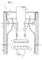
- a vacuum interrupter 1 is shown with a tubular insulating body, which comprises hollow cylindrical ceramic insulators 2 and 3 and is closed at one end face by means of a metallic flange 4 vacuum-tight.
- a fixed-contact power supply pin 5 which is connected outside the vacuum tube with a connecting line figuratively not shown, is passed through the vacuum-tight vacuum through the flange 4 and inside the vacuum interrupter 1 has a fixed contact 6 of a contact system 7.
- the contact system 7 further comprises a moving contact 8, which is also connected by means of a power supply pin 9, with a further connection line, not shown figuratively outside the vacuum tube 1.
- the moving contact 8 is arranged vacuum-tight and movable on the vacuum tube, so that the moving contact 8 can be moved in the direction of the movement arrow A toward the fixed contact 6 or away from the fixed contact 6 via a drive device, not shown figuratively, in order accordingly to form or separate a conductive connection.
- a control electrode 10 is arranged, which has a galvanic connection with the flange 4.
- the free end 11 of the control electrode 10 in the interior of the vacuum tube 1 is curved in the direction of the ceramic insulator 2 in the manner of a torus.
- a vapor shield 12 made of a conductive material, such as stainless steel, insulating secured, so that the vapor shield 12 has no fixed potential.
- the free end 13 of the vapor shield 12 overlaps in the axial direction of the vacuum interrupter 1, the control electrode 10 and has in the overlap region on a feeder 14, which is arranged opposite a constriction 15 of the power supply pin 5.
- the constriction 15 of the power supply pin 5, the intake 14 of the steam shield 12 and the torus-like curved free end 11 of the control electrode 10 are arranged lying in the axial direction of the vacuum interrupter 1 at the same height.
- the control electrode 10 via the metallic flange 4 with the power supply pin 5 in a galvanic connection and is thus at the same potential as the power supply pin 5 of the fixed contact 6.
- the control electrode 10 thus serves for potential control along the ceramic insulators.
- the vapor shield 12 serves as a plasma barrier to the ceramic in order to protect the ceramic insulators 2, 3 from vapor deposition during switching operations in which a current flows and possibly an arc is ignited.
- the vapor shield 12 is formed of a conductive material, and shaped so that occurring electric fields in the interior of the vacuum interrupter 1 are as homogeneous as possible.
- the power supply pin 5 therefore has the constriction 15 in the region in which the control electrode 10 has a toroidal curvature towards the ceramic insulator 2, and the steamer 12 likewise has a feeder 14 whose geometry is similar to that of the torus of FIG Control electrode corresponds.
- the contraction of the constriction 15 of the power supply pin 5 corresponds to the intake 14 of the steam shield 12.
- the inventive geometric arrangement with the constriction 15, the intake 14 of the vapor shield 12 and the toroidal curvature 11 of the control electrode 10 is ensured that the resulting electric field over the entire range as homogeneously as possible. With such an arrangement, thus a likelihood of flashover between the individual elements of the vacuum interrupter 1 is minimized, thereby improving the dielectric isolation.
- the depth of the constriction 15 is chosen so that the total resistance of the tube increases only slightly. at According to the arrangement of the invention, the dielectric isolation path is increased by a distance X3 corresponding to the depth of the constriction 15 of the power supply pin 5.
- FIG. 2 shows a further view of the embodiment of the vacuum interrupter 1 with open contact system 7.
- the moving contact power supply pin 9 is led out by a metallic end plate 16 by means of a bellows 17 vacuum-tight and movable from the vacuum interrupter 1 and with a drive unit, not shown figuratively for initiating a movement coupled.
- a control electrode 18 is galvanically connected to the end plate 17 and terminates toroidally at its end 19.
- the free end 20 of the vapor shield 12 overlaps in the axial direction of the vacuum interrupter 1, the control electrode 18 and has in the overlap region inwardly a feeder 21, which is opposite to a sidecut 22 of the power supply pin 9.
- the waist 22 of the power supply pin 9, the feeder 21 of the steam shield 12 and the torus-like curved free end 19 of the control electrode 18 are arranged lying in the axial direction of the vacuum interrupter 1 at the same height.
- the sidecut 22 of the moving contact power supply pin 9 is arranged so that it faces the feeder 21 of the vapor shield 12 when the contact system 7 of the vacuum interrupter 1 is open.
- the contact system 7 when the contact system 7 is open, the field is homogenized, since the distances X5 between the power supply pin 9 and the vapor shield 12 or X4 between the vapor shield 12 and the control electrode 18 are approximately the same throughout the overlap region, and especially in the area of the sidecut 22 Distances X5 'between the power supply pin 9 and retraction 21 of the steam shield 12 or X4' between intake 21 of the vapor shield 12 and toroidal end 19 of the control electrode 18 also correspond approximately to the values X5 and X4.
- the depth X6 of the waist 22 is also chosen so that the total resistance of the tube increases only slightly.
- the dielectric isolation distance is increased by a distance X6 corresponding to the depth of the sidecut 22 of the moving contact power supply pin 9.
- the sidecut 22 of the moving contact power supply pin 9 may also be formed extended in the direction of movement, for example by a length which corresponds to the nominal stroke of the vacuum interrupter and thus the moving distance of the moving contact.
- Such an elongated waist 22 ' is in the FIG. 2 shown in dashed lines and serves to achieve during a separation process of the contact system already a homogenization of the electric field.
Landscapes
- High-Tension Arc-Extinguishing Switches Without Spraying Means (AREA)
- Cookers (AREA)
- Electrophonic Musical Instruments (AREA)
- Supplying Of Containers To The Packaging Station (AREA)
Description
- Die Erfindung betrifft eine Vakuumschaltröhre mit einem rohrförmigen Isolierkörper und einem Kontaktsystem aus einem Bewegkontakt und einem Festkontakt, welche jeweils mit vakuumdicht aus der Vakuumschaltröhre herausgeführten Stromzuführungsbolzen verbunden sind, sowie einer galvanisch mit dem Festkontakt-Stromzuführungsbolzen verbundenen Steuerelektrode und einem an dem Isolierkörper angeordneten leitfähigen, die Steuerelektrode in einer Axialrichtung überlappenden Dampfschirm.
- Eine derartige Vakuumschaltröhre ist aus der
DE 92 11 970 U1 bekannt. Die dort offenbarte Vakuumschaltröhre umfasst einen Dampfschirm, welcher an einem metallischen Zwischenring an dem Isolierkörper der Vakuumschaltröhre gehalten ist und eine mit einem Flansch galvanische verbundene Steuerelektrode axial überlappt, so dass durch den Dampfschirm eine Plasmabarriere zu dem keramischen Isolierkörper gebildet ist, wodurch eine Bedampfung des Isolierkörpers bei Schalthandlungen mit einem Lichtbogen verhindert wird. Des Weiteren dienen die Steuerelektroden und der Dampfschirm zu einer Potentialsteuerung in der Vakuumschaltröhre, um die dielektrisch isolierenden Eigenschaften zu verbessern. DokumentGB-A-1 190 442 - Aufgabe der vorliegenden Erfindung ist es, eine Vakuumschaltröhre der eingangs erwähnten Art auszubilden, welche verbesserte dielektrische Isolationseigenschaften aufweist.
- Erfindungsgemäß gelöst wird diese Aufgabe dadurch, dass
- der Festkontakt-Stromzuführungsbolzen der Kontur des Dampfschirms entsprechend eingeschnürt und die Ein schnürung so angeordnet ist, dass sich der eingezogene Bereich des Dampfschirms um die Einschnürung erstreckt.
- Durch die erfindungsgemäß vorgesehene, im Überlappungsbereich mit dem Dampfschirm nach Art eines Torus auslaufende Steuerelektrode wird in vorteilhafter Weise im Bereich des Festkontakt-Stromzuführungsbolzens die dielektrische Festigkeit verbessert, wobei zusätzlich durch den dem Torus entsprechend nach innen eingezogenen Dampfschirm und den der Kontur des Dampfschirm entsprechend eingeschnürten Festkontakt-Stromzuführungsbolzens und die Anordnung der Einschnürung für einen homogenen Feldverlauf gesorgt ist.
- Ebenfalls ausgehend von der Vakuumschaltröhre nach der
DE 92 11 970 U1 betrifft die Erfindung ferner eine Vakuumschaltröhre mit einem rohrförmigen Isolierkörper und einem Kontaktsystem aus einem Bewegkontakt und einem Festkontakt, welche jeweils mit vakuumdicht aus der Vakuumschaltröhre herausgeführten Stromzuführungsbolzen verbunden sind, sowie einer galvanisch mit dem Bewegkontakt-Stromzuführungsbolzen verbundenen Steuerungselektrode und einem an dem Isolierkörper angeordneten leitfähigen, die Steuerungselektrode in einer Axialrichtung überlappenden Dampfschirm. - Zur Lösung der oben genannten Aufgabe läuft hier erfindungsgemäß
- der Bewegkontakt-Stromzuführungsbolzen weist eine Taillierung derart auf, dass sich der eingezogene Bereich des Dampfschirms in einer geöffneten Position des Kontaktsystems um die Taillierung erstreckt.
- Durch die erfindungsgemäß vorgesehene, im Überlappungsbereich mit dem Dampfschirm nach Art eines Torus auslaufende Steuerungselektrode wird in vorteilhafter Weise im Bereich des Bewegkontakt-Stromzuführungsbolzens die dielektrische Festigkeit verbessert, wobei zusätzlich durch den dem Torus entsprechend nach innen eingezogenen Dampfschirm und die Taillierung des Bewegkontakt-Stromzuführungsbolzens für einen homogenen Feldverlauf bei geöffnetem Kontaktsystem gesorgt ist.
- In weiterer Ausgestaltung entspricht die Taillierung des Bewegkontakt-Stromzuführungsbolzens in ihrer Kontur der des nach innen eingezogenen Dampfschirms. Eine solche Taillierung bietet eine einfache Möglichkeit, bei geöffnetem Kontaktsystem einen homogenen Feldverlauf auszubilden.
- In einer anderen bevorzugten Ausgestaltung ist die Taillierung des Bewegkontakt-Stromzuführungsbolzens in Axialrichtung vom Bewegkontakt weg um höchstens eine einer Bewegstrecke des Bewegkontaktes entsprechenden Länge verlängert ist. Mittels einer derartigen Verlängerung der Taillierung des Bewegkontakt-Stromzuführungsbolzens wird eine Homogenisierung des Feldverlaufs während des Öffnungsvorganges des Kontaktsystems erreicht.
- In einer bevorzugten Ausführungsform erstreckt sich die Steuerelektrode vom Isolierkörper in Richtung des Dampfschirms. Bei einer solchen Ausgestaltung der Steuerelektrode kann in vorteilhafter Weise der Torus mit einem größeren Radius ausgebildet sein.
- In einer bevorzugten Ausführungsform ist der Dampfschirm aus Edelstahl. Edelstahl ist ein vorteilhaftes Material, da bei einer ausreichenden Leitfähigkeit die Induktion von Wirbelströmen in dem Dampfschirm verringert wird.
- Die Erfindung wird anhand eines Ausführungsbeispiels mit Bezug auf die beigefügte Zeichnung erläutert. Es zeigen:
- Fig. 1
- eine Querschnittsansicht im Bereich des Festkon- takt-Stromzuführungsbolzens einer erfindungsgemäßen Vakuumschaltröhre; und
- Fig. 2
- eine weitere Querschnittsansicht im Bereich des Be- wegkontakt-Stromzuführungsbolzens einer erfindungs- gemäßen Vakuumschaltröhre.
- In der
Figur 1 ist eine Vakuumschaltröhre 1 mit einem rohrförmigen Isolierkörper dargestellt, welcher hohlzylindrische Keramikisolatoren 2 und 3 umfasst und an einer Stirnseite mittels eines metallischen Flansches 4 vakuumdicht abgeschlossen ist. Durch den Flansch 4 hindurch erstreckt sich ein Festkontakt-Stromzuführungsbolzen 5, welcher außerhalb der Vakuumröhre mit einer figürlich nicht dargestellten Anschlussleitung verbunden ist, durch den Flansch 4 vakuumdicht hindurchgeführt ist und im Inneren der Vakuumschaltröhre 1 einen Festkontakt 6 eines Kontaktsystems 7 aufweist. Das Kontaktsystem 7 umfasst des Weiteren einen Bewegkontakt 8, welcher ebenfalls mittels eines Stromzuführungsbolzens 9, mit einer figürlich nicht dargestellten weiteren Anschlussleitung außerhalb der Vakuumröhre 1 verbunden ist. Der Bewegkontakt 8 ist an der Vakuumröhre vakuumdicht und beweglich angeordnet, so dass über eine figürlich nicht dargestellte Antriebsvorrichtung der Bewegkontakt 8 in Richtung des Bewegungspfeiles A zu dem Festkontakt 6 hin bzw. von dem Festkontakt 6 weg bewegt werden kann, um entsprechend eine leitende Verbindung auszubilden oder zu trennen. Zwischen dem Flansch 4 und dem Keramikisolator 2 ist eine Steuerelektrode 10 angeordnet, welche mit dem Flansch 4 eine galvanische Verbindung aufweist. Das freie Ende 11 der Steuerelektrode 10 im Inneren der Vakuumröhre 1 ist in Richtung des Keramikisolators 2 nach Art eines Torus gewölbt. Zwischen den beiden Keramikisolatoren 2 und 3 ist ein Dampfschirm 12 aus einem leitenden Material, beispielsweise Edelstahl, isolierend befestigt, so dass der Dampfschirm 12 kein festgelegtes Potential aufweist. Das freie Ende 13 des Dampfschirms 12 überlappt in axialer Richtung der Vakuumschaltröhre 1 die Steuerelektrode 10 und weist im Überlappungsbereich einen Einzug 14 auf, welcher einer Einschnürung 15 des Stromzuführungsbolzens 5 gegenüberliegend angeordnet ist. Die Einschnürung 15 des Stromzuführungsbolzens 5, der Einzug 14 des Dampfschirms 12 sowie das torusartig gewölbte freie Ende 11 der Steuerelektrode 10 sind in axialer Richtung der Vakuumschaltröhre 1 auf gleicher Höhe liegend angeordnet. - Bei der Vakuumschaltröhre 1 des erfindungsgemäßen Ausführungsbeispiels steht die Steuerelektrode 10 über den metallischen Flansch 4 mit dem Stromzuführungsbolzen 5 in einer galvanischen Verbindung und liegt somit auf dem gleichen Potential wie der Stromzuführungsbolzen 5 des Festkontaktes 6. Die Steuerelektrode 10 dient somit zur Potentialsteuerung längs der Keramikisolatoren. Der Dampfschirm 12 dient als Plasmabarriere zur Keramik, um bei Schalthandlungen, bei welchen ein Strom fließt und gegebenenfalls ein Lichtbogen gezündet wird, die Keramikisolatoren 2, 3 gegenüber einer Bedampfung zu schützen. Um die dielektrische Isolation in der Vakuumschaltröhre 1 bestmöglich zu gewährleisten, ist der Dampfschirm 12 aus einem leitenden Material ausgebildet, und derartig geformt, dass auftretende elektrische Felder im Inneren der Vakuumschaltröhre 1 möglichst homogen sind. Bei der erfindungsgemäßen Vakuumschaltröhre 1 weist der Stromzuführungsbolzen 5 daher die Einschnürung 15 in dem Bereich auf, in welchem die Steuerelektrode 10 eine torusartige Wölbung hin zum Keramikisolator 2 aufweist, und der Dampfschirm 12 weist ebenfalls einen Einzug 14 auf, welcher in seiner Geometrie dem Torus der Steuerelektrode entspricht. Die Kontur der Einschnürung 15 des Stromzuführungsbolzens 5 entspricht dem Einzug 14 des Dampfschirms 12. Bei einer derartigen Einschnürung 15 und einem entsprechenden Einzug 14 ist gewährleistet, dass die Abstände X1 zwischen Stromzuführungsbolzen 5 und Dampfschirm 12 bzw. X2 zwischen Dampfschirm 12 und Steuerelektrode 10 im gesamten Überlappungsbereich in etwa den gleichen Wert aufweisen, und insbesondere im Bereich der Einschnürung 15 auch die Abstände X1' zwischen Stromzuführungsbolzen 5 und Einzug 14 des Dampfschirms 11 bzw. X2' zwischen Einzug 14 des Dampfschirms 12 und Steuerelektrode 10 ebenfalls in etwa den Werten X1 bzw. X2 entsprechen. Durch die isolierende Anordnung des Dampfschirms 12 stellt sich auf diesem ein Potential von etwa der Hälfte des Potentials von Steuerelektrode 10 und Stromzuführungsbolzen 5 ein. Durch die erfindungsgemäße geometrische Anordnung mit der Einschnürung 15, dem Einzug 14 des Dampfschirms 12 und der torusartigen Wölbung 11 der Steuerelektrode 10 ist dabei gewährleistet, dass das entstehende elektrische Feld über den gesamten Bereich möglichst homogen verläuft. Bei einer derartigen Anordndung ist,somit eine Wahrscheinlichkeit eines Überschlags zwischen den einzelnen Elementen der Vakuumschaltröhre 1 minimiert und dadurch die dielektrische Isolation verbessert. Die Tiefe der Einschnürung 15 ist dabei so gewählt, dass sich der Gesamtwiderstand der Röhre nur unwesentlich erhöht. Bei der erfindungsgemäßen Anordnung ist die dielektrische Isolationsstrecke um eine Strecke X3 entsprechend der Tiefe der Einschnürung 15 des Stromzuführungsbolzens 5 erhöht.
-
Figur 2 zeigt eine weitere Ansicht des Ausführungsbeispiels der Vakuumschaltröhre 1 mit geöffnetem Kontaktsystem 7. Der Bewegkontakt-Stromzuführungs-bolzen 9 ist durch eine metallische Endplatte 16 mittels eines Faltenbalges 17 vakuumdicht und beweglich aus der Vakuumschaltröhre 1 herausgeführt und mit einer figürlich nicht dargestellten Antriebseinheit zum Einleiten einer Bewegung gekoppelt. Eine Steuerungselektrode 18 ist galvanisch mit der Endplatte 17 verbunden und läuft an ihrem Ende 19 torusartig aus. Das freie Ende 20 des Dampfschirms 12 überlappt in axialer Richtung der Vakuumschaltröhre 1 die Steuerungselektrode 18 und weist im Überlappungsbereich nach innen einen Einzug 21 auf, welcher einer Taillierung 22 des Stromzuführungsbolzens 9 gegenüberliegend angeordnet ist. Die Taillierung 22 des Stromzuführungsbolzens 9, der Einzug 21 des Dampfschirms 12 sowie das torusartig gewölbte freie Ende 19 der Steuerungselektrode 18 sind in axialer Richtung der Vakuumschaltröhre 1 auf gleicher Höhe liegend angeordnet. - Die Taillierung 22 des Bewegkontakt-Stromzuführungsbolzen 9 ist dabei so angeordnet, dass sie bei geöffnetem Kontaktsystem 7 der Vakuumschaltröhre 1 dem Einzug 21 des Dampfschirms 12 gegenüberliegt. Dadurch wird bei geöffnetem Kontaktsystem 7 eine Homogenisierung des Feldes erreicht, da die Abstände X5 zwischen Stromzuführungsbolzen 9 und Dampfschirm 12 bzw. X4 zwischen Dampfschirm 12 und Steuerungselektrode 18 im gesamten Überlappungsbereich in etwa den gleichen Wert aufweisen, und insbesondere im Bereich der Taillierung 22 auch die Abstände X5' zwischen Stromzuführungsbolzen 9 und Einzug 21 des Dampfschirms 12 bzw. X4' zwischen Einzug 21 des Dampfschirms 12 und torusartigem Ende 19 der Steuerungselektrode 18 ebenfalls in etwa den Werten X5 bzw. X4 entsprechen. Die Tiefe X6 der Taillierung 22 ist dabei ebenfalls so gewählt, dass sich der Gesamtwiderstand der Röhre nur unwesentlich erhöht. Bei der erfindungsgemäßen Anordnung ist die dielektrische Isolationsstrecke um eine Strecke X6 entsprechend der Tiefe der Taillierung 22 des Bewegkontakt-Stromzuführungsbolzens 9 erhöht.
- Die Taillierung 22 des Bewegkontakt-Stromzuführungsbolzens 9 kann aber auch in der Bewegungsrichtung verlängert ausgebildet sein, beispielsweise um eine Länge, welche dem Nennhub der Vakuumschaltröhre und damit der Bewegstrecke des Bewegkontaktes entspricht. Eine derartig verlängerte Taillierung 22' ist in der
Figur 2 gestrichelt dargestellt und dient dazu, während eines Trennungsvorgangs des Kontaktsystems bereits eine Homogenisierung des elektrischen Feldes zu erreichen. -
- 1
- Vakuumschaltröhre
- 2, 3
- Keramikisolatoren
- 4
- metallischer Flansch
- 5
- Festkontakt-Stromzuführungsbolzen
- 6
- Festkontakt
- 7
- Kontaktsystem
- 8
- Bewegkontakt
- 9
- Stromzuführungsbolzen
- 10
- Steuerelektrode
- 11
- torusartig gewölbtes Ende
- 12
- Dampfschirm
- 13
- freies Ende
- 14
- Einzug
- 15
- Einschnürung
- 16
- metallische Endplatte
- 17
- Faltenbalg
- 18
- Steuerungselektrode
- 19
- torusartig gewölbtes Ende
- 20
- freies Ende
- 21
- Einzug
- 22
- Taillierung
- 22'
- Taillierung
- A
- Bewegungspfeil
- X1, X1'
- Abstand Festkontakt-Stromzuführungsbolzen - Dampf- schirm
- X2, X2'
- Abstand Steuerelektrode - Dampfschirm
- X3
- Einschnürungstiefe
- X4, X4'
- Abstand Steuerungselektrode - Dampfschirm
- X5, X5'
- Abstand Bewegkontakt-Stromzuführungsbolzen - Dampf- schirm
- X6
- Taillierungstiefe
Claims (6)
- Vakuumschaltröhre (1) mit einem rohrförmigen Isolierkörper (2, 3) und einem Kontaktsystem (7) aus einem Bewegkontakt (8) und einem Festkontakt (6), welche jeweils mit vakuumdicht aus der Vakuumschaltröhre herausgeführten Stromzuführungsbolzen (5,9) verbunden sind, sowie einer galvanisch mit dem Festkontakt-Stromzuführungsbolzen (5) verbundenen Steuerelektrode (10) und einem an dem Isolierkörper (2, 3) angeordneten leitfähigen, die Steuerelektrode (10) in einer Axialrichtung überlappenden Dampfschirm (12), wobei- die Steuerelektrode (10) im Überlappungsbereich mit dem Dampfschirm (12) nach Art eines Torus ausläuft, und- der Dampfschirm (12) dem Torus entsprechend nach innen eingezogen ist, dadurch gekennzeichnet, dass- der Festkontakt-Stromzuführungsbolzen (5) der Kontur des Dampfschirms (12) entsprechend eingeschnürt ist und die Einschnürung (15) so angebracht ist, dass sich der eingezogene Bereich des Dampfschirms (12) um die Einschnürung erstreckt.
- Vakuumschaltröhre (1) mit einem rohrförmigen Isolierkörper (2, 3) und einem Kontaktsystem (7) aus einem Bewegkontakt (8) und einem Festkontakt (6), welche jeweils mit vakuumdicht aus der Vakuumschaltröhre herausgeführten Stromzuführungsbolzen (5,9) verbunden sind, sowie einer galvanisch mit dem Bewegkontakt-Stromzuführungsbolzen (9) verbundenen Steuerungselektrode (18) und einem an dem Isolierkörper (2, 3) angeordneten leitfähigen, die Steuerungselektrode (18) in einer Axialrichtung überlappenden Dampfschirm (12), wobei- die Steuerungselektrode (18) im Überlappungsbereich mit dem Dampfschirm (12) nach Art eines Torus aus läuft, und- der Dampfschirm (12) dem Torus entsprechend nach innen eingezogen ist dadurch gekennzeichnet, dass- der Bewegkontakt-Stromzuführungsbolzen (9) eine Taillierung (22) derart aufweist, dass sich der eingezogene Bereich (21) des Dampfschirms (12) in einer geöffneten Position des Kontaktsystems um die Taillierung (22) erstreckt.
- Vakuumschaltröhre nach Anspruch 2,
dadurch gekennzeichnet, dass
die Taillierung (22) des Bewegkontakt-Stromzuführungsbolzens (9) in ihrer Kontur der des nach innen eingezogenen Dampfschirms (12) entspricht. - Vakuumschaltröhre nach Anspruch 2,
dadurch gekennzeichnet, dass
die Taillierung (22) des Bewegkontakt-Stromzuführungsbolzens (9) in Axialrichtung vom Bewegkontakt (8) weg um höchstens eine einer Bewegstrecke des Bewegkontaktes (8) entsprechenden Länge verlängert ist. - Vakuumschaltröhre nach einem der vorangehenden Ansprüche,
dadurch gekennzeichnet, dass
sich die Steuerelektrode (10) vom Isolierkörper in Richtung des Dampfschirms (12) erstreckt. - Vakuumschaltröhre nach einem der vorangehenden Ansprüche,
dadurch gekennzeichnet, dass
der Dampfschirm (12) aus Edelstahl ist.
Applications Claiming Priority (1)
| Application Number | Priority Date | Filing Date | Title |
|---|---|---|---|
| PCT/DE2005/002245 WO2007068218A1 (de) | 2005-12-12 | 2005-12-12 | Vakuumschaltröhre |
Publications (2)
| Publication Number | Publication Date |
|---|---|
| EP1961029A1 EP1961029A1 (de) | 2008-08-27 |
| EP1961029B1 true EP1961029B1 (de) | 2009-12-02 |
Family
ID=36660743
Family Applications (1)
| Application Number | Title | Priority Date | Filing Date |
|---|---|---|---|
| EP05825892A Expired - Lifetime EP1961029B1 (de) | 2005-12-12 | 2005-12-12 | Vakuumschaltröhre |
Country Status (6)
| Country | Link |
|---|---|
| US (1) | US20080314874A1 (de) |
| EP (1) | EP1961029B1 (de) |
| CN (1) | CN101326606A (de) |
| AT (1) | ATE450875T1 (de) |
| DE (2) | DE112005003823A5 (de) |
| WO (1) | WO2007068218A1 (de) |
Families Citing this family (3)
| Publication number | Priority date | Publication date | Assignee | Title |
|---|---|---|---|---|
| DE102008026799B4 (de) * | 2008-06-02 | 2010-04-15 | Siemens Aktiengesellschaft | Vakuumschaltröhre |
| MX2013000127A (es) * | 2010-07-07 | 2013-07-03 | Siemens Ltd | Aislante electrico. |
| DE102016218385A1 (de) | 2016-09-23 | 2018-03-29 | Siemens Aktiengesellschaft | Isolierteil mit gewölbtem Metallschirm |
Family Cites Families (6)
| Publication number | Priority date | Publication date | Assignee | Title |
|---|---|---|---|---|
| GB1190442A (en) * | 1967-02-20 | 1970-05-06 | Ass Elect Ind | Improvements relating to Vacuum Electric Switches and like Discharge Devices |
| US4061894A (en) * | 1976-04-28 | 1977-12-06 | General Electric Company | Vacuum-type circuit interrupter with improved protection for bellows |
| JPS5855609B2 (ja) * | 1979-07-23 | 1983-12-10 | 株式会社明電舎 | 真空しや断器 |
| US4665287A (en) * | 1985-11-08 | 1987-05-12 | General Electric Company | Shield assembly of a vacuum interrupter |
| US5189270A (en) * | 1990-08-03 | 1993-02-23 | Hitachi, Ltd. | Contact structure for vacuum circuit breaker |
| US5438174A (en) * | 1993-11-22 | 1995-08-01 | Eaton Corporation | Vacuum interrupter with a radial magnetic field |
-
2005
- 2005-12-12 EP EP05825892A patent/EP1961029B1/de not_active Expired - Lifetime
- 2005-12-12 DE DE112005003823T patent/DE112005003823A5/de not_active Withdrawn
- 2005-12-12 AT AT05825892T patent/ATE450875T1/de not_active IP Right Cessation
- 2005-12-12 DE DE502005008656T patent/DE502005008656D1/de not_active Expired - Lifetime
- 2005-12-12 CN CNA200580052280XA patent/CN101326606A/zh active Pending
- 2005-12-12 US US12/096,971 patent/US20080314874A1/en not_active Abandoned
- 2005-12-12 WO PCT/DE2005/002245 patent/WO2007068218A1/de not_active Ceased
Also Published As
| Publication number | Publication date |
|---|---|
| DE112005003823A5 (de) | 2008-11-27 |
| CN101326606A (zh) | 2008-12-17 |
| WO2007068218A1 (de) | 2007-06-21 |
| DE502005008656D1 (de) | 2010-01-14 |
| ATE450875T1 (de) | 2009-12-15 |
| EP1961029A1 (de) | 2008-08-27 |
| US20080314874A1 (en) | 2008-12-25 |
Similar Documents
| Publication | Publication Date | Title |
|---|---|---|
| EP2156454B1 (de) | Schaltpol für ein hochspannungsnetz | |
| EP2647024B1 (de) | Elektrokontaktanordnung | |
| DE2443141C3 (de) | Vakuumschalter mit einem Vakuumgehäuse | |
| EP0176665A2 (de) | Vollfeststoffisolierter Vakuumschalter | |
| DE2557197C2 (de) | Vakuumschalter | |
| DE10221580B3 (de) | Unterbrechereinheit eines Hochspannungs-Leistungsschalters | |
| EP2452352B1 (de) | Vakuumschaltröhre | |
| EP2526560A1 (de) | Vakuumschaltröhre | |
| EP3491656B1 (de) | Vakuumschalter | |
| DE19631323C1 (de) | Druckgasschalter | |
| DE602005001955T2 (de) | Befestigungsvorrichtung für einen Schutzschirm in einem elektrischen Schalter, insbesondere einem Vakuumschalter. | |
| EP2384513A1 (de) | Vakuumschaltröhre | |
| EP1961029A1 (de) | Vakuumschaltröhre | |
| DE68927533T2 (de) | Trenner für gasisolierte Schaltanlage | |
| DE1282768B (de) | Spulenanordnung zur Erzeugung eines Magnetfeldes in einem elektrischen Leistungsschalter | |
| EP1691389A1 (de) | Schaltkammer für einen gasisolierten Hochspannungsschalter | |
| DE4422316B4 (de) | Vakuumschaltröhre mit ringförmigem Isolator | |
| EP0225562B1 (de) | Vakuumschaltröhre | |
| EP4341976B1 (de) | Vakuumschaltröhre und anordnung mit vakuumschaltröhren sowie verfahren zum absteuern von vakuumschaltröhren | |
| DE2416747B2 (de) | Vakuumleistungsschalter | |
| DE102011006013B3 (de) | Vakuumschaltröhre und Schalterpol | |
| DE1963625A1 (de) | Vakuumschalter | |
| DE102008031472B4 (de) | Vakuumschaltröhre | |
| DE3904147C2 (de) | ||
| DE969871C (de) | Leistungsschalter mit zentripetaler Beblasung des Lichtbogens und zylindrische Form aufweisenden Kontakten |
Legal Events
| Date | Code | Title | Description |
|---|---|---|---|
| PUAI | Public reference made under article 153(3) epc to a published international application that has entered the european phase |
Free format text: ORIGINAL CODE: 0009012 |
|
| 17P | Request for examination filed |
Effective date: 20080502 |
|
| AK | Designated contracting states |
Kind code of ref document: A1 Designated state(s): AT BE BG CH CY CZ DE DK EE ES FI FR GB GR HU IE IS IT LI LT LU LV MC NL PL PT RO SE SI SK TR |
|
| RTI1 | Title (correction) |
Free format text: VACUUM INTERRUPTER |
|
| GRAP | Despatch of communication of intention to grant a patent |
Free format text: ORIGINAL CODE: EPIDOSNIGR1 |
|
| DAX | Request for extension of the european patent (deleted) | ||
| GRAS | Grant fee paid |
Free format text: ORIGINAL CODE: EPIDOSNIGR3 |
|
| GRAA | (expected) grant |
Free format text: ORIGINAL CODE: 0009210 |
|
| AK | Designated contracting states |
Kind code of ref document: B1 Designated state(s): AT BE BG CH CY CZ DE DK EE ES FI FR GB GR HU IE IS IT LI LT LU LV MC NL PL PT RO SE SI SK TR |
|
| REG | Reference to a national code |
Ref country code: GB Ref legal event code: FG4D Free format text: NOT ENGLISH |
|
| REG | Reference to a national code |
Ref country code: CH Ref legal event code: EP |
|
| REG | Reference to a national code |
Ref country code: IE Ref legal event code: FG4D |
|
| REF | Corresponds to: |
Ref document number: 502005008656 Country of ref document: DE Date of ref document: 20100114 Kind code of ref document: P |
|
| REG | Reference to a national code |
Ref country code: NL Ref legal event code: VDEP Effective date: 20091202 |
|
| PG25 | Lapsed in a contracting state [announced via postgrant information from national office to epo] |
Ref country code: SE Free format text: LAPSE BECAUSE OF FAILURE TO SUBMIT A TRANSLATION OF THE DESCRIPTION OR TO PAY THE FEE WITHIN THE PRESCRIBED TIME-LIMIT Effective date: 20091202 Ref country code: LT Free format text: LAPSE BECAUSE OF FAILURE TO SUBMIT A TRANSLATION OF THE DESCRIPTION OR TO PAY THE FEE WITHIN THE PRESCRIBED TIME-LIMIT Effective date: 20091202 Ref country code: FI Free format text: LAPSE BECAUSE OF FAILURE TO SUBMIT A TRANSLATION OF THE DESCRIPTION OR TO PAY THE FEE WITHIN THE PRESCRIBED TIME-LIMIT Effective date: 20091202 |
|
| LTIE | Lt: invalidation of european patent or patent extension |
Effective date: 20091202 |
|
| PG25 | Lapsed in a contracting state [announced via postgrant information from national office to epo] |
Ref country code: SI Free format text: LAPSE BECAUSE OF FAILURE TO SUBMIT A TRANSLATION OF THE DESCRIPTION OR TO PAY THE FEE WITHIN THE PRESCRIBED TIME-LIMIT Effective date: 20091202 Ref country code: PL Free format text: LAPSE BECAUSE OF FAILURE TO SUBMIT A TRANSLATION OF THE DESCRIPTION OR TO PAY THE FEE WITHIN THE PRESCRIBED TIME-LIMIT Effective date: 20091202 Ref country code: LV Free format text: LAPSE BECAUSE OF FAILURE TO SUBMIT A TRANSLATION OF THE DESCRIPTION OR TO PAY THE FEE WITHIN THE PRESCRIBED TIME-LIMIT Effective date: 20091202 Ref country code: CY Free format text: LAPSE BECAUSE OF FAILURE TO SUBMIT A TRANSLATION OF THE DESCRIPTION OR TO PAY THE FEE WITHIN THE PRESCRIBED TIME-LIMIT Effective date: 20091202 |
|
| BERE | Be: lapsed |
Owner name: SIEMENS A.G. Effective date: 20091231 |
|
| PGFP | Annual fee paid to national office [announced via postgrant information from national office to epo] |
Ref country code: TR Payment date: 20100218 Year of fee payment: 6 |
|
| REG | Reference to a national code |
Ref country code: IE Ref legal event code: FD4D |
|
| PG25 | Lapsed in a contracting state [announced via postgrant information from national office to epo] |
Ref country code: IS Free format text: LAPSE BECAUSE OF FAILURE TO SUBMIT A TRANSLATION OF THE DESCRIPTION OR TO PAY THE FEE WITHIN THE PRESCRIBED TIME-LIMIT Effective date: 20100402 Ref country code: EE Free format text: LAPSE BECAUSE OF FAILURE TO SUBMIT A TRANSLATION OF THE DESCRIPTION OR TO PAY THE FEE WITHIN THE PRESCRIBED TIME-LIMIT Effective date: 20091202 Ref country code: IE Free format text: LAPSE BECAUSE OF FAILURE TO SUBMIT A TRANSLATION OF THE DESCRIPTION OR TO PAY THE FEE WITHIN THE PRESCRIBED TIME-LIMIT Effective date: 20091202 Ref country code: MC Free format text: LAPSE BECAUSE OF NON-PAYMENT OF DUE FEES Effective date: 20100701 Ref country code: ES Free format text: LAPSE BECAUSE OF FAILURE TO SUBMIT A TRANSLATION OF THE DESCRIPTION OR TO PAY THE FEE WITHIN THE PRESCRIBED TIME-LIMIT Effective date: 20100313 Ref country code: NL Free format text: LAPSE BECAUSE OF FAILURE TO SUBMIT A TRANSLATION OF THE DESCRIPTION OR TO PAY THE FEE WITHIN THE PRESCRIBED TIME-LIMIT Effective date: 20091202 Ref country code: PT Free format text: LAPSE BECAUSE OF FAILURE TO SUBMIT A TRANSLATION OF THE DESCRIPTION OR TO PAY THE FEE WITHIN THE PRESCRIBED TIME-LIMIT Effective date: 20100402 Ref country code: RO Free format text: LAPSE BECAUSE OF FAILURE TO SUBMIT A TRANSLATION OF THE DESCRIPTION OR TO PAY THE FEE WITHIN THE PRESCRIBED TIME-LIMIT Effective date: 20091202 Ref country code: BG Free format text: LAPSE BECAUSE OF FAILURE TO SUBMIT A TRANSLATION OF THE DESCRIPTION OR TO PAY THE FEE WITHIN THE PRESCRIBED TIME-LIMIT Effective date: 20100302 |
|
| REG | Reference to a national code |
Ref country code: CH Ref legal event code: PL |
|
| PG25 | Lapsed in a contracting state [announced via postgrant information from national office to epo] |
Ref country code: SK Free format text: LAPSE BECAUSE OF FAILURE TO SUBMIT A TRANSLATION OF THE DESCRIPTION OR TO PAY THE FEE WITHIN THE PRESCRIBED TIME-LIMIT Effective date: 20091202 Ref country code: CZ Free format text: LAPSE BECAUSE OF FAILURE TO SUBMIT A TRANSLATION OF THE DESCRIPTION OR TO PAY THE FEE WITHIN THE PRESCRIBED TIME-LIMIT Effective date: 20091202 |
|
| PLBE | No opposition filed within time limit |
Free format text: ORIGINAL CODE: 0009261 |
|
| STAA | Information on the status of an ep patent application or granted ep patent |
Free format text: STATUS: NO OPPOSITION FILED WITHIN TIME LIMIT |
|
| PG25 | Lapsed in a contracting state [announced via postgrant information from national office to epo] |
Ref country code: GR Free format text: LAPSE BECAUSE OF FAILURE TO SUBMIT A TRANSLATION OF THE DESCRIPTION OR TO PAY THE FEE WITHIN THE PRESCRIBED TIME-LIMIT Effective date: 20100303 Ref country code: BE Free format text: LAPSE BECAUSE OF NON-PAYMENT OF DUE FEES Effective date: 20091231 Ref country code: CH Free format text: LAPSE BECAUSE OF NON-PAYMENT OF DUE FEES Effective date: 20091231 Ref country code: LI Free format text: LAPSE BECAUSE OF NON-PAYMENT OF DUE FEES Effective date: 20091231 |
|
| 26N | No opposition filed |
Effective date: 20100903 |
|
| PG25 | Lapsed in a contracting state [announced via postgrant information from national office to epo] |
Ref country code: DK Free format text: LAPSE BECAUSE OF FAILURE TO SUBMIT A TRANSLATION OF THE DESCRIPTION OR TO PAY THE FEE WITHIN THE PRESCRIBED TIME-LIMIT Effective date: 20091202 |
|
| PGFP | Annual fee paid to national office [announced via postgrant information from national office to epo] |
Ref country code: FR Payment date: 20101230 Year of fee payment: 6 |
|
| PG25 | Lapsed in a contracting state [announced via postgrant information from national office to epo] |
Ref country code: IT Free format text: LAPSE BECAUSE OF FAILURE TO SUBMIT A TRANSLATION OF THE DESCRIPTION OR TO PAY THE FEE WITHIN THE PRESCRIBED TIME-LIMIT Effective date: 20091202 |
|
| PGFP | Annual fee paid to national office [announced via postgrant information from national office to epo] |
Ref country code: GB Payment date: 20101209 Year of fee payment: 6 |
|
| PG25 | Lapsed in a contracting state [announced via postgrant information from national office to epo] |
Ref country code: LU Free format text: LAPSE BECAUSE OF NON-PAYMENT OF DUE FEES Effective date: 20091212 |
|
| PG25 | Lapsed in a contracting state [announced via postgrant information from national office to epo] |
Ref country code: AT Free format text: LAPSE BECAUSE OF NON-PAYMENT OF DUE FEES Effective date: 20091212 |
|
| PG25 | Lapsed in a contracting state [announced via postgrant information from national office to epo] |
Ref country code: HU Free format text: LAPSE BECAUSE OF FAILURE TO SUBMIT A TRANSLATION OF THE DESCRIPTION OR TO PAY THE FEE WITHIN THE PRESCRIBED TIME-LIMIT Effective date: 20100603 |
|
| GBPC | Gb: european patent ceased through non-payment of renewal fee |
Effective date: 20111212 |
|
| REG | Reference to a national code |
Ref country code: FR Ref legal event code: ST Effective date: 20120831 |
|
| PG25 | Lapsed in a contracting state [announced via postgrant information from national office to epo] |
Ref country code: GB Free format text: LAPSE BECAUSE OF NON-PAYMENT OF DUE FEES Effective date: 20111212 |
|
| PG25 | Lapsed in a contracting state [announced via postgrant information from national office to epo] |
Ref country code: FR Free format text: LAPSE BECAUSE OF NON-PAYMENT OF DUE FEES Effective date: 20120102 |
|
| PGFP | Annual fee paid to national office [announced via postgrant information from national office to epo] |
Ref country code: DE Payment date: 20130218 Year of fee payment: 8 |
|
| PG25 | Lapsed in a contracting state [announced via postgrant information from national office to epo] |
Ref country code: TR Free format text: LAPSE BECAUSE OF NON-PAYMENT OF DUE FEES Effective date: 20111212 |
|
| REG | Reference to a national code |
Ref country code: DE Ref legal event code: R119 Ref document number: 502005008656 Country of ref document: DE |
|
| REG | Reference to a national code |
Ref country code: DE Ref legal event code: R119 Ref document number: 502005008656 Country of ref document: DE Effective date: 20140701 |
|
| PG25 | Lapsed in a contracting state [announced via postgrant information from national office to epo] |
Ref country code: DE Free format text: LAPSE BECAUSE OF NON-PAYMENT OF DUE FEES Effective date: 20140701 |