EP1960796B1 - Precision flexible current sensor - Google Patents
Precision flexible current sensor Download PDFInfo
- Publication number
- EP1960796B1 EP1960796B1 EP05813809.0A EP05813809A EP1960796B1 EP 1960796 B1 EP1960796 B1 EP 1960796B1 EP 05813809 A EP05813809 A EP 05813809A EP 1960796 B1 EP1960796 B1 EP 1960796B1
- Authority
- EP
- European Patent Office
- Prior art keywords
- sensing
- wires
- shielding
- current sensor
- wound
- Prior art date
- Legal status (The legal status is an assumption and is not a legal conclusion. Google has not performed a legal analysis and makes no representation as to the accuracy of the status listed.)
- Not-in-force
Links
Images


Classifications
-
- G—PHYSICS
- G01—MEASURING; TESTING
- G01R—MEASURING ELECTRIC VARIABLES; MEASURING MAGNETIC VARIABLES
- G01R15/00—Details of measuring arrangements of the types provided for in groups G01R17/00 - G01R29/00, G01R33/00 - G01R33/26 or G01R35/00
- G01R15/14—Adaptations providing voltage or current isolation, e.g. for high-voltage or high-current networks
- G01R15/18—Adaptations providing voltage or current isolation, e.g. for high-voltage or high-current networks using inductive devices, e.g. transformers
- G01R15/181—Adaptations providing voltage or current isolation, e.g. for high-voltage or high-current networks using inductive devices, e.g. transformers using coils without a magnetic core, e.g. Rogowski coils
Description
- The invention is related to sensor circuit for electrical alternating current. More particularly, the invention is directed to improvement of mechanical construction. Examples relate to electrical configuration, electronic evaluation circuit and use of flexible current sensor.
- The flexible current sensors are based on flexible inductive coil, which can be formed to create closed path around the measured current carrying conductor. The voltage induced into coil is proportional to the derivation of the total current flowing through the enclosed area. This principle of current measurement is well known as Rogowski principle or Rogowski coil following the publication by Rogowski W. and Steinhaus W. in 1912. Flexible current sensor generally has a form of sensing cable equipped with mechanical coupling system for either fixing or releasing said sensor cable ends to and from mutually closed position. The sensing cable consists of sensing coil wound on cylindrical flexible core, optional electrical shielding located over said sensing coil and outer isolation coat. In order to convert the coil voltage to output signal proportional to current an electronic integrator circuit is usually part of the flexible current sensor. The flexible sensors are advantageous for measurement of current in large size wires, difficult shape conductors and conductor groups.
- Known constructions of the flexible current sensors have lower amplitude and phase accuracy compare to ferromagnetic current transformer types. The accuracy of flexible current sensors is affected mainly by sensor coil inhomogenity and by residual signals captured via capacitive and inductive coupling to strange voltage and current sources. Due to low level of the output voltage of the sensor coil they are sensitive to disturbance, interference and noise generated in evaluation electronics. Commercially available flexible current sensors are due to insufficient accuracy dedicated mainly for informative measurements.
- Relevant solutions for Rogowski coil arrangements and respective electronics can be found in following references:
US pat. No.4689546 (Stephens et al ) discloses arrangement of air core current transformers. - UK patent No.
GB2259150A -
US pat. No.5442280 discloses fixed Rogowski coil arrangements on printed circuit layout. - European Patent
EP652441A1 -
US pat. No.6614218B1 discloses arrangements of combined passive and active integrator. - European Patent
EP0834745A2 discloses arrangement of fixed Rogowski coil with high homogeneity. - Japanese patent
JP2000065866 - UK patent application No.
GB2332784A - German patent application No.
DE19811366A1 discloses flexible Rogowski coil arrangements optimized for repeated assembling on power line. - UK patent No.
GB2342783A - German patent application No.
DE19959789A1 discloses arrangements of electronic integrator with switched DC feedback. -
US pat. No.6825650B1 discloses arrangements of series of fixed Rogowski coils for current measurement in electricity meter. -
US pat. No.6313623B1 discloses spatial arrangements of two Rogowski coils eliminating residual signals. - US pat. Application No.
US2003/0090356A1 discloses fixed Rogowski coil arrangements on printed circuit layout with optic transmission path. - The extreme linearity, lack of saturation of the non magnetic core and practically non limited frequency range are inherent property of the Rogowski principle based current sensors. These properties still invoke demand for their improvement and application oriented optimization.
-
US pat. No. 4689546 discloses Rogowski coil equipped with cascade of integrator circuit improving the frequency range of the sensor. -
US pat. No.5012218 of Hauget al discloses compensation coil arrangement to minimise the end gap influence of the standard Rogowski coil sensor with central return wire. - German pat. No.
2432919 of Hidde and Mueller discloses method of construction of fixed air core transformer consisting of areal arangement of mutually interconnected rigid coils. -
US pat. 6963195 of Bergcan discloses arrangement of air-core fixed senig coil arrangement with sensing coil and shielding coil about pair of primary current conductors. - Pat.
WO-A-9628737 - Therefore, it is an object for this invention to provide new and improved arrangement of flexible current sensor. Examples relate to its evaluation electronics yielding higher accuracy to and improvements in its applications.
- Improvement of flexible current sensor according to the invention as defined in claims 1 and 3, wherein:
- The electrical shielding of the sensing cable consists of plurality of individually isolated shielding wires. The shielding wires are arranged into groups wound in mutually opposite directions. All shielding wires are electrically interconnected in parallel. Each shielding wire has only one connection point. Symmetrical arrangement of shielding consisting of plurality of wires yields high flexibility of sensing cable and minimizes the shielding effective impedance and thus increases the shielding performance.
- The single connection point of each shielding wire eliminates any flow of induced currents, which would affect accuracy.
- The sensing coil consists of plurality of individually isolated sensing wires. The sensing wires are arranged into groups wound in mutually opposite directions. The sensing wires, respective to voltages induced in sensing wires by magnetic field of sensed current, are electrically interconnected in series or in parallel or in combination of series and parallel or some sensing wires are idle. The interconnection configuration of sensing wires is used to determine the sensing coil sensitivity, impedance and frequency range. Symmetrical arrangement of sensing wires eliminates influence of strange current sources.
- The shielding wires wound in opposite direction can be advantageously mutually twisted. The shielding wire twisting improves the mechanical stability of the winding and increases effective coverage. The shielding wire twisting also improves the electrical symmetry of wire groups thus lowering shielding impedance yielding further increasing of shielding performance.
- The sensing wires wound in opposite direction can be advantageously mutually twisted. The sensing wire twisting improves the mechanical stability of the winding and thus increases the electrical stability as well. Essential effect of sensing wire twisting is the improvement of symmetry of sensing coil in reference to shielding. The symmetry enables elimination of all common mode residual signals induced by unwanted couplings of the sensing coil to strange sources
- The flexible current sensor cable can be advantageously manufactured as continuous cable product on coaxial cable making machine with shielding wires and sensing wires arranged according to invention. The final sensor is then assembled from portion of desired length cut from already manufactured continuous cable. Continuous cable production assures high homogeneity of windings along the cable length thus increasing the sensor's accuracy and manufacturing repeatability. Further advantage is the lower manufacturing cost compare to individual sensor production.
- Sensing coil inhomogenity caused by sensing coil termination and coupling system can be effectively reduced by compensation coil connected in series with sensing coil. The compensation coil can be advantageously located within the coupling system.
- The symmetrical sensing coil of flexible current sensor is electrically balanced relative to shielding. Therefore essential elimination of all common mode residual signals induced by unwanted couplings of the sensing coil to strange sources can be accomplished by differential input stage of the electronic evaluation circuit. For low frequency applications the high impedance of input circuit assures high sensitivity and independence of output signal on the sensing coil resistance. For signals with high frequency content the sensing wires of sensing coil act as balanced transmission line with distributed parameters. For flat high frequency response the transmission line have to be matched with impedance equal to its characteristic impedance.
- One alternative of coupling system for flexible current sensor consists of pair of cylindrical caps wherein each cap is from its back side equipped with cable hole for sensor cable, wherein first cap of said pair is on its front side equipped with cap hole for partial sinking of the front side of said second cap of said pair, wherein the wall of the cap hole is equipped with two fixing holes perpendicular to cap axis located on cap diagonal in opposite positions, wherein said second cap of said pair is equipped with fixing tips fitting into said fixing holes of the first cap, wherein one fixing hole is equipped with guiding notch for the fixing tip.
- Another alternative of coupling system for flexible current sensor consists of plurality of segments equipped with tunnel for sensor cable and with facet or facet pairs. The facet system creates either closed path tunnel when multiple segments are stacked on one combination of facets and facet pairs or open path tunnel when multiple segments are stacked on another combination of facets and facet pairs.
- Segments of the coupling system can be advantageously equipped with tip/hole pairs for determination of segment position in stack of segments.
- Segments of the coupling system can be advantageously equipped with tunnels for stack positioning strings.
- Flexible current sensor according to invention can be assembled from desired length portion of continuous sensor cable. Such sensor can be advantageously used as means for residual current measurement in large conductor groups for example building wiring and measurement of surge or lightning total and/or partial current in large structures for example buildings, towers or masts.
- Due to low sensitivity of the flexible current sensor according to invention to strange signals and capability to spatial adjustment this flexible current sensor can be advantageously used as current measurement means within measuring devices for example in electricity meters.
- The DC offset on output of electronic integrator circuit for flexible current sensor can be eliminated without affecting the AC accuracy in circuit consisting of operational amplifier, input resistor, integrating capacitor, decupling capacitor, first filter resistor, second filter resistor and filter capacitor. The input resistor is connected between input terminal of the integrator and inverting input terminal of the operational amplifier, the integrating capacitor is connected between inverting input terminal of the operational amplifier and output terminal of the integrator. The decupling capacitor is connected between output terminal of the operational amplifier and the integrator output terminal. The second filter resistor is connected between output terminal of the operational amplifier and first terminal of the filter capacitor. The first filter resistor is connected between inverting input terminal of the operational amplifier and first terminal of the filter capacitor. The second terminal of the filter capacitor is connected to electrical reference potential. The non-inverting input terminal of the operational amplifier is connected to electrical reference potential. The decoupling capacitor eliminates output of the DC content. The amplitude and phase accuracy is not affected by decoupling capacitor as the integrator's control feedback via integrating capacitor is taken directly from the output terminal.
- Flexible current sensor cable sample according to invention has been manufactured for verification purpose as a continuous cable with sensing coil consisting of 2 x 4 isolated wires wound and twisted in mutually opposite direction on 7 mm diameter plastic core interconnected in series and with shielding consisting of 2 x 10⁸ isolated wires wound and twisted in mutually opposite direction interconnected in parallel. Total outer diameter of the outer coat was 12 mm. The sensor was equipped with coupling system consisting of pair of cylindrical caps. The realized sensor has been used in precision electrical power measurement application as input circuit of working standard for electricity meter testing. The accuracy of the test system inclusive flexible sensor has been determined to be within limits 0.1% in amplitude and 0.1° in phase.
-
-
Figure 1 shows principle of wire arrangement of shielding and/or sensing coil wound on cylindrical flexible core according to invention. -
Figure 2 shows an example of parallel interconnection of shielding wires according to invention. -
Figure 3 shows an example of serial interconnection of sensing wires according to invention. -
Figure 4 shows an example of combination of serial and parallel interconnection of sensing wires. -
Figure 5 shows an example of differential input arrangement of electronic integrator circuit. -
Figure 6 shows example of minimized coupling system for flexible current sensor. -
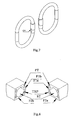
Figure 7 shows example of flexible current sensor assembled with coupling system according tofigure 6 . -
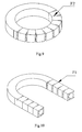
Figure 8 shows an example of segment construction of coupling system for flexible current sensor. -
Figure 9 shows a closed arrangement of the coupling system according tofigure 8 . -
Figure 10 shows an open arrangement of the coupling system according tofigure 8 . -
Figure 11 shows example fragment of flexible current sensor in current measurement application inside electricity meter. -
Figure 12 shows example of flexible current sensor application for discharge current measurement on high voltage mast. -
Figure 13 shows a minimized example of electronic integrator circuit for flexible current sensor. -
Figure 1 shows the principle of wire interconnection of shielding and/or sensing coil wound on cylindrical flexible core FC according to invention. The coil consists of plurality of individually isolated wires. The wires are divided into two groups G1 and G2. The groups G1 and G2 are wound in mutually opposite directions and the wires of both groups are mutually twisted via periodic interchange of radial position. -
Figure 2 shows an example of parallel interconnection of shielding wires according to invention. The shielding wires are divided into groups G1 and G2 wound in opposite direction. All shielding wires are electrically interconnected in parallel. Each shielding wire has only one connection point to common terminal T. The parallel configuration of wires of two equal groups wound in opposite direction mutually cancels the magnetic field caused by common capacitive coupling to external voltage source. Therefore the parallel configuration acts as low impedance compact shielding but with advantage of high mechanical flexibility and elimination of measurement error introduced by residual current, which would be induced by magnetic field of sensed current in compact shielding. -
Figure 3 shows an example of serial interconnection of sensing wires according to invention. The sensing wires are divided into two groups G1 and G2. The groups are wound in mutually opposite directions. All sensing wires are electrically interconnected in series. The voltages induced in individual wires by magnetic field of sensed current are in this arrangement added. The sum of voltages appears on terminals T1 and T2. This arrangement is dedicated for applications where the highest sensitivity is required. -
Figure 4 shows an example of combination of serial and parallel interconnection of sensing wires. The groups G1 and G2 are interconnected in series while the sensing wires of individual groups are electrically interconnected in parallel. This arrangement is dedicated for high current transient measurement applications in which low sensitivity, low coil impedance and broad frequency range is required. -
Figure 5 shows an example of differential input arrangement of electronic integrator circuit. The terminals T1 and T2 of sensor coil SC are connected to non-inverting and inverting inputs of differential amplifier DA. The common terminal T of parallel connected shielding wires is connected to electrical ground. The output of differential input stage DA is connected to input of electronic integrator EI. Optional matching by impedance ZL terminating the sensor coil optimizes the high frequency response of the sensor coil. -
Figure 6 shows example of minimized coupling system for flexible current sensor. The fixing system consists of pair of cylindrical caps wherein each cap is in its back side equipped with cable hole SH for sensor cable, wherein first cap of said pair is on its front side equipped with cap hole CH for partial sinking of the front side of said second cap of said pair, wherein the wall of the cap hole CH is equipped with two fixing holes FH perpendicular to cap axis located on cap diagonal in opposite positions, wherein said second cap of said pair is equipped with fixing tips FT fitting into said fixing holes FH of the first cap, wherein one fixing hole FH is equipped with guiding notch GN for fixing tip FT. This fixing system has no moving part and therefore it is very compact and reliable. -
Figure 7 shows two views of flexible current sensor assembled with coupling system shown infigure 6 . The appropriate assembling with the guiding notch GN located on the inner diameter of the closed sensor uses the natural centrifugal force of the bended sensor cable for additional fixation of the fixing caps in closed position. -
Figure 8 shows an example of segment construction of coupling system for flexible current sensor. Coupling system for flexible current sensor consists of plurality of segments. The segments are equipped with tunnel ST for sensor and with facet pairs F1a / F1b and F2a / F2b. The segments are equipped with tip/hole pairs THP for determination of segment position in stack of segments. The segments are equipped with tunnels PT for stack positioning strings. -
Figure 9 shows an example of closed arrangement of the coupling system shown infig. 8 . Multiple segments are stacked on facets F2 and create closed path tunnel for sensor core. This is the working arrangement for measurement of current flowing through wire enclosed by the sensor. -
Figure 10 shows an example of open arrangement of the coupling system shown infig. 8 . Multiple segments are stacked on facets F1 and create open path tunnel for sensor core. This is the positioning arrangement when the sensor can be positioned over current carrying wire and then closed to working arrangement. -
Figure 11 shows example fragment of flexible current sensor in current measurement application inside electricity meter. The meter's current wire CW is sensed by multiple turns of sensor cable SC according to invention. Multiple turn lead to proportional sensitivity increase. -
Figure 12 shows example of flexible current sensor application for discharge current measurement on high voltage mast. The mast is equipped with flexible current sensor cable SC for measurement of total current flowing through mast stem into the earth. -
Figure 13 shows a minimized example of electronic integrator circuit for flexible current sensor. Electronic integrator circuit consists of operational amplifier OA, input resistor RI, integrating capacitor C1, decupling capacitor CD, first filter resistor RF1, second filter resistor RF2 and filter capacitor CF. The input resistor RI is connected between integrator input terminal and inverting input terminal of operational amplifier OA. The integrating capacitor C1 is connected between inverting input terminal of the operational amplifier OA and integrator output terminal. The decupling capacitor CD is connected between output terminal of the operational amplifier OA and integrator output terminal. The second filter resistor RF2 is connected between output terminal of the operational amplifier OA and first terminal of the filter capacitor CF. The first filter resistor RF1 is connected between inverting input terminal of the operational amplifier OA and first terminal of the filter capacitor CF. Second terminal of the filter capacitor CF is connected to electrical reference potential. Non-inverting input terminal of the operational amplifier OA is connected to electrical reference potential. Output signal of the integrator circuit is free of DC offset due to decoupling capacitor CD. The amplitude and phase accuracy is not affected by decoupling capacitor CD as the integrator control feedback via integrating capacitor C1 is taken from the integrator output terminal.
Claims (5)
- A flexible current sensor in form of a sensor cable consisting of a sensing coil wound on a cylindrical flexible core, an electrical shielding located over said sensing coil and an outer isolation coat equipped with a mechanical coupling system for either fixing or releasing sensor cable ends to and from mutually closed position, said electrical shielding comprising a symmetrical arrangement consisting of a plurality of individually isolated shielding wires arranged into groups wound along the length of said cylindrical flexible core in mutually opposite directions wherein said individually isolated shielding wires are mutually electrically interconnected in parallel, and each shielding wire has only one connection point.
- A flexible current sensor according to claim 1, characterised in that said sensing coil consists of a plurality of individually isolated sensing wires arranged into groups wound in mutually opposite directions.
- A flexible current sensor in form of a sensor cable consisting of a sensing coil wound on a cylindrical flexible core, an electrical shielding located over said sensing coil and an outer isolation coat equipped with a mechanical coupling system for either fixing or releasing sensor cable ends to and from mutually closed position, said sensing coil consists of a plurality of individually isolated sensing wires arranged into two groups wherein said groups are wound in mutually opposite directions and the sensing wires of both groups are mutually twisted via periodic interchange of radial position.
- A flexible current sensor according to claim 2 or 3, characterised in that said sensing wires, respective to voltages induced in the sensing wires by the magnetic field of a sensed current, are electrically interconnected in series or in parallel or a combination of series and parallel or some sensing wires remain idle respective to voltages induced in the sensing wires by the magnetic field of the sensed current, wherein a configuration of said sensing wires is determined by a required sensitivity, an impedance and a frequency range of said current sensor.
- The flexible current sensor according to claim 1, wherein said shielding wires wound in opposite direction are mutually twisted.
Applications Claiming Priority (1)
| Application Number | Priority Date | Filing Date | Title |
|---|---|---|---|
| PCT/SK2005/000023 WO2007061390A1 (en) | 2005-11-28 | 2005-11-28 | Precision flexible current sensor |
Publications (2)
| Publication Number | Publication Date |
|---|---|
| EP1960796A1 EP1960796A1 (en) | 2008-08-27 |
| EP1960796B1 true EP1960796B1 (en) | 2014-05-07 |
Family
ID=36649533
Family Applications (1)
| Application Number | Title | Priority Date | Filing Date |
|---|---|---|---|
| EP05813809.0A Not-in-force EP1960796B1 (en) | 2005-11-28 | 2005-11-28 | Precision flexible current sensor |
Country Status (4)
| Country | Link |
|---|---|
| US (1) | US7847543B2 (en) |
| EP (1) | EP1960796B1 (en) |
| JP (1) | JP4972098B2 (en) |
| WO (1) | WO2007061390A1 (en) |
Families Citing this family (55)
| Publication number | Priority date | Publication date | Assignee | Title |
|---|---|---|---|---|
| WO2007061390A1 (en) * | 2005-11-28 | 2007-05-31 | Ladislav Grno | Precision flexible current sensor |
| FR2923019A1 (en) * | 2007-10-26 | 2009-05-01 | Schneider Electric Ind Sas | Current e.g. short-circuit current, measuring device e.g. flexible and adjustable circular rogowski current sensor, for on-site functioning test application, has bypass unit bypassing wire extending between points and end point of wire |
| GB2461494B (en) * | 2008-01-29 | 2012-03-07 | Weston Aerospace Ltd | Speed sensor |
| FR2931945B1 (en) * | 2008-05-22 | 2010-06-18 | Billanco | MAGNETIC FIELD CIRCULATION SENSOR AND CURRENT SENSOR EMPLOYING SUCH A SENSOR |
| IT1391344B1 (en) * | 2008-07-14 | 2011-12-05 | Lorenzo Peretto | ELECTRIC STABILIZABLE TRANSDUCER. |
| US8421443B2 (en) * | 2008-11-21 | 2013-04-16 | Veris Industries, Llc | Branch current monitor with calibration |
| US8193818B2 (en) * | 2009-01-15 | 2012-06-05 | Hamilton Sundstrand Corporation | Partial corona discharge detection |
| US9823274B2 (en) | 2009-07-31 | 2017-11-21 | Pulse Electronics, Inc. | Current sensing inductive devices |
| US9664711B2 (en) | 2009-07-31 | 2017-05-30 | Pulse Electronics, Inc. | Current sensing devices and methods |
| GB0913571D0 (en) * | 2009-08-04 | 2009-09-16 | Ea Tech Ltd | Current detector |
| US20110043190A1 (en) * | 2009-08-20 | 2011-02-24 | Farr Lawrence B | Rogowski coil, medium voltage electrical apparatus including the same, and method of providing electrostatic shielding for a rogowski coil |
| US8508071B1 (en) * | 2009-12-18 | 2013-08-13 | Synapse Wireless, Inc. | Systems and methods for combining current from solar power arrays |
| EA027503B1 (en) * | 2010-07-02 | 2017-08-31 | Белкин Интернэшнл, Инк. | Systems and methods for measuring electrical power usage in a structure and systems and methods of calibrating the same |
| US9588160B2 (en) | 2011-02-09 | 2017-03-07 | International Business Machines Corporation | Wire manager with current and voltage sensing |
| US9063184B2 (en) | 2011-02-09 | 2015-06-23 | International Business Machines Corporation | Non-contact current-sensing and voltage-sensing clamp |
| US8680845B2 (en) | 2011-02-09 | 2014-03-25 | International Business Machines Corporation | Non-contact current and voltage sensor |
| US8508212B2 (en) | 2011-06-14 | 2013-08-13 | International Business Machines Corporation | Calibration of non-contact current sensors |
| US9000752B2 (en) | 2011-06-14 | 2015-04-07 | International Business Machines Corporation | Multi-conductor cable current and voltage sensors |
| US9429595B2 (en) * | 2011-09-09 | 2016-08-30 | Aclara Meters Llc | Sensor devices and methods for use in sensing current through a conductor |
| US9075091B2 (en) | 2011-09-09 | 2015-07-07 | General Electric Company | Sensor devices and methods for use in sensing current through a conductor |
| US9081040B2 (en) | 2011-09-09 | 2015-07-14 | General Electric Company | Sensor devices and methods for use in sensing current through a conductor |
| US8912807B2 (en) | 2011-09-09 | 2014-12-16 | General Electric Company | Sensor devices and methods for use in sensing current through a conductor |
| US8829888B2 (en) | 2011-09-09 | 2014-09-09 | General Electric Company | Sensor devices and methods for use in sensing current through a conductor |
| US9015326B2 (en) | 2011-09-14 | 2015-04-21 | General Electric Company | Method and system for managing power consumption of a meter during communication activities |
| US8799481B2 (en) | 2011-09-14 | 2014-08-05 | General Electric Company | Method and system for detection of communication activities of a meter board |
| US8719681B2 (en) | 2011-09-14 | 2014-05-06 | General Electric Company | Diagnostic tool for metrology errors caused by communication activities |
| MX2014004430A (en) * | 2011-10-12 | 2014-10-06 | Cequent Performance Prod Inc | Current sensing electrical converter. |
| TWI436083B (en) | 2011-11-02 | 2014-05-01 | Ind Tech Res Inst | Proximity current sensing apparatus and method |
| GB201122328D0 (en) * | 2011-12-23 | 2012-02-01 | Dames Andrew N | Flexible rogowski current sensor |
| FR2987897A1 (en) * | 2012-03-06 | 2013-09-13 | Julien Bergoz | Measurement device for use in online carrier current receiver to measure current flowing in e.g. electrical conductive wire, has analysis element and/or processing element for analyzing and/or processing electrical signal at terminals |
| US9304149B2 (en) | 2012-05-31 | 2016-04-05 | Pulse Electronics, Inc. | Current sensing devices and methods |
| ES2438618B8 (en) * | 2012-06-15 | 2014-09-10 | Centro De Investigaciones Energéticas, Medioambientales Y Tecnológicas (Ciemat) | Rogowski coil and procedure to measure the current flowing through a conductor |
| US9007077B2 (en) | 2012-08-28 | 2015-04-14 | International Business Machines Corporation | Flexible current and voltage sensor |
| US9310397B2 (en) | 2013-01-29 | 2016-04-12 | International Business Machines Corporation | Multi-branch current/voltage sensor array |
| US9671434B2 (en) | 2014-08-08 | 2017-06-06 | Aclara Meters Llc | Sensor devices and methods for use in sensing current through a conductor |
| US10371730B2 (en) | 2015-12-28 | 2019-08-06 | Veris Industries, Llc | Branch current monitor with client level access |
| US10371721B2 (en) | 2015-12-28 | 2019-08-06 | Veris Industries, Llc | Configuration system for a power meter |
| US10274572B2 (en) | 2015-12-28 | 2019-04-30 | Veris Industries, Llc | Calibration system for a power meter |
| US10408911B2 (en) | 2015-12-28 | 2019-09-10 | Veris Industries, Llc | Network configurable system for a power meter |
| DE102016124165A1 (en) * | 2016-12-13 | 2018-06-14 | Dr. Ing. H.C. F. Porsche Aktiengesellschaft | Method and sensor for measuring an alternating current |
| US10732208B2 (en) * | 2017-02-13 | 2020-08-04 | Ladislav Gr{hacek over (n)}o | Flexible current sensor with stranded core |
| US11215650B2 (en) | 2017-02-28 | 2022-01-04 | Veris Industries, Llc | Phase aligned branch energy meter |
| US11193958B2 (en) | 2017-03-03 | 2021-12-07 | Veris Industries, Llc | Non-contact voltage sensor |
| US10705126B2 (en) | 2017-05-19 | 2020-07-07 | Veris Industries, Llc | Energy metering with temperature monitoring |
| US10777349B2 (en) | 2017-10-23 | 2020-09-15 | Schweitzer Engineering Laboratories, Inc. | Current transformer with flexible secondary winding |
| CN107907802A (en) * | 2017-11-17 | 2018-04-13 | 国网湖南省电力有限公司 | A kind of powered partial discharge detection sensor of high-tension cable and its application process |
| GB2579027B (en) | 2018-11-14 | 2021-06-09 | Megger Instruments Ltd | Multi-use test lead. |
| US10984940B2 (en) | 2018-12-10 | 2021-04-20 | Schweitzer Engineering Laboratories, Inc. | Compression housing for a laminate core of an inductive current transformer |
| US20220230850A1 (en) * | 2019-05-07 | 2022-07-21 | Lam Research Corporation | Voltage and current probe |
| EP3783370A1 (en) * | 2019-08-20 | 2021-02-24 | LEM International SA | Rogowski current transducer |
| FR3108986B1 (en) * | 2020-04-02 | 2022-04-15 | Safran Electrical & Power | Very wide bandwidth current sensor |
| CN111487450B (en) * | 2020-04-29 | 2022-08-16 | 连云港灌源科技有限公司 | Method for expanding bandwidth of Rogowski coil current sensor |
| FR3116125B1 (en) * | 2020-11-09 | 2023-10-20 | Safran Electrical & Power | Current sensor and current sensor transducer assembly system |
| FR3117600B1 (en) * | 2020-12-14 | 2022-12-23 | Safran Electrical & Power | Two-in-one wire-wound current sensor |
| US11418026B1 (en) * | 2021-03-22 | 2022-08-16 | International Business Machines Corporation | Electrostatic protection device |
Family Cites Families (32)
| Publication number | Priority date | Publication date | Assignee | Title |
|---|---|---|---|---|
| US3924223A (en) * | 1974-02-21 | 1975-12-02 | Westinghouse Electric Corp | Power line communication system having a protective terminating impedance arrangement |
| DE2432919A1 (en) | 1974-07-05 | 1976-02-12 | Siemens Ag | Current transformer based on magnetic voltmeter - has measuring frame assembled of individual coils |
| FR2559268B1 (en) | 1984-02-06 | 1986-05-09 | Centre Nat Rech Scient | DEVICE FOR MEASURING AN ELECTRIC CURRENT USING A REGULAR TORO-SHAPED SOLENOID |
| US4689546A (en) * | 1985-12-18 | 1987-08-25 | General Electric Company | Internal armature current monitoring in large three-phase generator |
| US4700131A (en) * | 1986-04-07 | 1987-10-13 | Westinghouse Electric Corp. | Mutual inductor current sensor |
| US4831327A (en) * | 1987-05-01 | 1989-05-16 | Hydro-Quebec | Self-powered electrical measuring system isolated from electrical perturbances |
| JP2713459B2 (en) * | 1988-05-07 | 1998-02-16 | エナジーサポート株式会社 | Zero-phase current detector |
| GB2259150B (en) | 1991-08-28 | 1995-07-26 | William Frederick Ray | Improvements in current measurement |
| FR2692074B1 (en) | 1992-06-05 | 1994-07-22 | Alsthom Gec | ROGOWSKI COIL. |
| FR2695482B1 (en) | 1992-09-10 | 1994-10-21 | Alsthom Gec | Measuring device using a Rogowski coil. |
| FR2712423B1 (en) | 1993-11-08 | 1996-02-09 | Gec Alsthom T & D Sa | Rogowski coil usable in an electrical installation with an earthed metal casing and method of manufacturing such a coil. |
| GB9505295D0 (en) | 1995-03-16 | 1995-05-03 | Btr Plc | Measurement of alternating current |
| DE19640981A1 (en) | 1996-10-04 | 1998-04-16 | Asea Brown Boveri | Rogowski coil |
| US6963195B1 (en) | 1997-08-15 | 2005-11-08 | General Electric Company | Apparatus for sensing current |
| EP0934532B1 (en) * | 1997-08-28 | 2006-03-22 | General Electric Company | Self powered current sensor |
| GB9726306D0 (en) | 1997-12-13 | 1998-02-11 | Rocoil Limited | Measuring device |
| WO1999046607A1 (en) * | 1998-03-13 | 1999-09-16 | Florida International University | Apparatus for measuring high frequency currents |
| DE19811366A1 (en) | 1998-03-16 | 1999-09-30 | Moeller Gmbh | Current sensor |
| SE1073908T5 (en) * | 1998-04-22 | 2004-08-24 | Power Electronic Measurements | Stroemmaetningsanordning |
| JP2000065866A (en) | 1998-08-26 | 2000-03-03 | Nippon Telegr & Teleph Corp <Ntt> | Current probe |
| GB9821164D0 (en) | 1998-09-30 | 1998-11-25 | Ward David | Measuring device |
| ATE238561T1 (en) | 1999-01-29 | 2003-05-15 | Suparules Ltd | Clamp meter and electricity meter |
| GB9918539D0 (en) * | 1999-08-06 | 1999-10-06 | Sentec Ltd | Planar current transformer |
| DE19959789A1 (en) | 1999-12-07 | 2001-06-13 | Siemens Ag | Integrator circuit for trigger circuit of power switch with Rogowski coil |
| US6313623B1 (en) | 2000-02-03 | 2001-11-06 | Mcgraw-Edison Company | High precision rogowski coil |
| JP2001343402A (en) * | 2000-06-05 | 2001-12-14 | Mitsubishi Electric Corp | Dc current detector |
| DE20101454U1 (en) | 2001-01-27 | 2001-05-23 | Phoenix Contact Gmbh & Co | Circuit board-based current sensor |
| JP2002372552A (en) * | 2001-06-14 | 2002-12-26 | Mitsubishi Electric Corp | Current measuring device |
| JP2003130894A (en) | 2001-10-29 | 2003-05-08 | Toshiba Corp | Current transformer |
| FR2870040B1 (en) * | 2004-05-10 | 2006-06-09 | Areva T & D Sa | ROGOWSKI TYPE WINDING CURRENT TRANSFORMER HAVING PARTIAL CIRCUITS ASSOCIATED IN FORMING A COMPLETE CIRCUIT |
| WO2007061390A1 (en) * | 2005-11-28 | 2007-05-31 | Ladislav Grno | Precision flexible current sensor |
| US7545138B2 (en) * | 2006-07-06 | 2009-06-09 | Schweitzer Engineering Laboratories, Inc. | Precision, temperature-compensated, shielded current measurement device |
-
2005
- 2005-11-28 WO PCT/SK2005/000023 patent/WO2007061390A1/en active Application Filing
- 2005-11-28 JP JP2008542285A patent/JP4972098B2/en not_active Expired - Fee Related
- 2005-11-28 EP EP05813809.0A patent/EP1960796B1/en not_active Not-in-force
-
2008
- 2008-05-28 US US12/154,921 patent/US7847543B2/en not_active Expired - Fee Related
Non-Patent Citations (2)
| Title |
|---|
| "Bifilar-Wikipedia", HTTP://DE.WIKIPEDIA.ORG, pages 1 - 2, Retrieved from the Internet <URL:http://de.wikipedia.org/wiki/Bifilar> [retrieved on 20130514] * |
| "Das magnetische Feld", WWW.SCHREIBEN10.COM, pages 1 - 6, Retrieved from the Internet <URL:http://www.schreiben10.com/referate/Physik/9/DAS-MAGNETISCHE-FELD-reon.php> [retrieved on 20130514] * |
Also Published As
| Publication number | Publication date |
|---|---|
| JP4972098B2 (en) | 2012-07-11 |
| US20080303511A1 (en) | 2008-12-11 |
| US7847543B2 (en) | 2010-12-07 |
| WO2007061390A1 (en) | 2007-05-31 |
| JP2009517659A (en) | 2009-04-30 |
| EP1960796A1 (en) | 2008-08-27 |
Similar Documents
| Publication | Publication Date | Title |
|---|---|---|
| EP1960796B1 (en) | Precision flexible current sensor | |
| US6965225B2 (en) | Coreless current sensor | |
| US10139432B2 (en) | Methods and systems relating to improved AC signal performance of dual stage transformers | |
| EP1183543B1 (en) | Electrical current sensor | |
| US7598724B2 (en) | Flexible current transformer assembly | |
| US20080106254A1 (en) | Split Rogowski coil current measuring device and methods | |
| US10545178B2 (en) | Current sensor for measuring an alternating current | |
| US7449637B2 (en) | Pulse current sensor | |
| US20120146620A1 (en) | Current sensor | |
| US10545177B2 (en) | Non-contact sensor based Rogowski coil | |
| US9081040B2 (en) | Sensor devices and methods for use in sensing current through a conductor | |
| US10295573B2 (en) | Compensated rogowski coil | |
| US20170059621A1 (en) | Low power based rogowski coil | |
| GB2259150A (en) | Current measurements | |
| US11686745B2 (en) | Rogowski current sensor which is fast and immune to voltage drifts | |
| EP1923709B1 (en) | Active linear current transducer | |
| RU2717397C1 (en) | Device and method for measuring current strength of one separate wire of multi-wire system | |
| CN108226602B (en) | Method and sensor for measuring the time derivative of an alternating current | |
| US11502436B2 (en) | Electrical connection for transferring signals while reducing interference | |
| Slomovitz et al. | Shielded electronic current transformer | |
| EP3566061B1 (en) | Flexible current sensor with stranded core | |
| WO2022171216A1 (en) | Partial discharge sensor |
Legal Events
| Date | Code | Title | Description |
|---|---|---|---|
| PUAI | Public reference made under article 153(3) epc to a published international application that has entered the european phase |
Free format text: ORIGINAL CODE: 0009012 |
|
| 17P | Request for examination filed |
Effective date: 20080630 |
|
| AK | Designated contracting states |
Kind code of ref document: A1 Designated state(s): AT BE BG CH CY CZ DE DK EE ES FI FR GB GR HU IE IS IT LI LT LU LV MC NL PL PT RO SE SI SK TR |
|
| DAX | Request for extension of the european patent (deleted) | ||
| 17Q | First examination report despatched |
Effective date: 20120709 |
|
| GRAP | Despatch of communication of intention to grant a patent |
Free format text: ORIGINAL CODE: EPIDOSNIGR1 |
|
| INTG | Intention to grant announced |
Effective date: 20140107 |
|
| GRAS | Grant fee paid |
Free format text: ORIGINAL CODE: EPIDOSNIGR3 |
|
| GRAA | (expected) grant |
Free format text: ORIGINAL CODE: 0009210 |
|
| AK | Designated contracting states |
Kind code of ref document: B1 Designated state(s): AT BE BG CH CY CZ DE DK EE ES FI FR GB GR HU IE IS IT LI LT LU LV MC NL PL PT RO SE SI SK TR |
|
| REG | Reference to a national code |
Ref country code: GB Ref legal event code: FG4D |
|
| RIN1 | Information on inventor provided before grant (corrected) |
Inventor name: GRNO, LADISLAV, |
|
| REG | Reference to a national code |
Ref country code: AT Ref legal event code: REF Ref document number: 667081 Country of ref document: AT Kind code of ref document: T Effective date: 20140515 |
|
| REG | Reference to a national code |
Ref country code: IE Ref legal event code: FG4D |
|
| REG | Reference to a national code |
Ref country code: DE Ref legal event code: R096 Ref document number: 602005043601 Country of ref document: DE Effective date: 20140618 |
|
| REG | Reference to a national code |
Ref country code: AT Ref legal event code: MK05 Ref document number: 667081 Country of ref document: AT Kind code of ref document: T Effective date: 20140507 |
|
| REG | Reference to a national code |
Ref country code: NL Ref legal event code: VDEP Effective date: 20140507 |
|
| REG | Reference to a national code |
Ref country code: LT Ref legal event code: MG4D |
|
| PG25 | Lapsed in a contracting state [announced via postgrant information from national office to epo] |
Ref country code: FI Free format text: LAPSE BECAUSE OF FAILURE TO SUBMIT A TRANSLATION OF THE DESCRIPTION OR TO PAY THE FEE WITHIN THE PRESCRIBED TIME-LIMIT Effective date: 20140507 Ref country code: IS Free format text: LAPSE BECAUSE OF FAILURE TO SUBMIT A TRANSLATION OF THE DESCRIPTION OR TO PAY THE FEE WITHIN THE PRESCRIBED TIME-LIMIT Effective date: 20140907 Ref country code: GR Free format text: LAPSE BECAUSE OF FAILURE TO SUBMIT A TRANSLATION OF THE DESCRIPTION OR TO PAY THE FEE WITHIN THE PRESCRIBED TIME-LIMIT Effective date: 20140808 Ref country code: LT Free format text: LAPSE BECAUSE OF FAILURE TO SUBMIT A TRANSLATION OF THE DESCRIPTION OR TO PAY THE FEE WITHIN THE PRESCRIBED TIME-LIMIT Effective date: 20140507 Ref country code: CY Free format text: LAPSE BECAUSE OF FAILURE TO SUBMIT A TRANSLATION OF THE DESCRIPTION OR TO PAY THE FEE WITHIN THE PRESCRIBED TIME-LIMIT Effective date: 20140507 |
|
| PG25 | Lapsed in a contracting state [announced via postgrant information from national office to epo] |
Ref country code: PL Free format text: LAPSE BECAUSE OF FAILURE TO SUBMIT A TRANSLATION OF THE DESCRIPTION OR TO PAY THE FEE WITHIN THE PRESCRIBED TIME-LIMIT Effective date: 20140507 Ref country code: AT Free format text: LAPSE BECAUSE OF FAILURE TO SUBMIT A TRANSLATION OF THE DESCRIPTION OR TO PAY THE FEE WITHIN THE PRESCRIBED TIME-LIMIT Effective date: 20140507 Ref country code: SE Free format text: LAPSE BECAUSE OF FAILURE TO SUBMIT A TRANSLATION OF THE DESCRIPTION OR TO PAY THE FEE WITHIN THE PRESCRIBED TIME-LIMIT Effective date: 20140507 Ref country code: LV Free format text: LAPSE BECAUSE OF FAILURE TO SUBMIT A TRANSLATION OF THE DESCRIPTION OR TO PAY THE FEE WITHIN THE PRESCRIBED TIME-LIMIT Effective date: 20140507 Ref country code: ES Free format text: LAPSE BECAUSE OF FAILURE TO SUBMIT A TRANSLATION OF THE DESCRIPTION OR TO PAY THE FEE WITHIN THE PRESCRIBED TIME-LIMIT Effective date: 20140507 |
|
| PG25 | Lapsed in a contracting state [announced via postgrant information from national office to epo] |
Ref country code: PT Free format text: LAPSE BECAUSE OF FAILURE TO SUBMIT A TRANSLATION OF THE DESCRIPTION OR TO PAY THE FEE WITHIN THE PRESCRIBED TIME-LIMIT Effective date: 20140908 |
|
| PG25 | Lapsed in a contracting state [announced via postgrant information from national office to epo] |
Ref country code: CZ Free format text: LAPSE BECAUSE OF FAILURE TO SUBMIT A TRANSLATION OF THE DESCRIPTION OR TO PAY THE FEE WITHIN THE PRESCRIBED TIME-LIMIT Effective date: 20140507 Ref country code: DK Free format text: LAPSE BECAUSE OF FAILURE TO SUBMIT A TRANSLATION OF THE DESCRIPTION OR TO PAY THE FEE WITHIN THE PRESCRIBED TIME-LIMIT Effective date: 20140507 Ref country code: RO Free format text: LAPSE BECAUSE OF FAILURE TO SUBMIT A TRANSLATION OF THE DESCRIPTION OR TO PAY THE FEE WITHIN THE PRESCRIBED TIME-LIMIT Effective date: 20140507 Ref country code: SK Free format text: LAPSE BECAUSE OF FAILURE TO SUBMIT A TRANSLATION OF THE DESCRIPTION OR TO PAY THE FEE WITHIN THE PRESCRIBED TIME-LIMIT Effective date: 20140507 Ref country code: BE Free format text: LAPSE BECAUSE OF FAILURE TO SUBMIT A TRANSLATION OF THE DESCRIPTION OR TO PAY THE FEE WITHIN THE PRESCRIBED TIME-LIMIT Effective date: 20140507 Ref country code: EE Free format text: LAPSE BECAUSE OF FAILURE TO SUBMIT A TRANSLATION OF THE DESCRIPTION OR TO PAY THE FEE WITHIN THE PRESCRIBED TIME-LIMIT Effective date: 20140507 |
|
| REG | Reference to a national code |
Ref country code: DE Ref legal event code: R097 Ref document number: 602005043601 Country of ref document: DE |
|
| PG25 | Lapsed in a contracting state [announced via postgrant information from national office to epo] |
Ref country code: NL Free format text: LAPSE BECAUSE OF FAILURE TO SUBMIT A TRANSLATION OF THE DESCRIPTION OR TO PAY THE FEE WITHIN THE PRESCRIBED TIME-LIMIT Effective date: 20140507 |
|
| PLBE | No opposition filed within time limit |
Free format text: ORIGINAL CODE: 0009261 |
|
| STAA | Information on the status of an ep patent application or granted ep patent |
Free format text: STATUS: NO OPPOSITION FILED WITHIN TIME LIMIT |
|
| 26N | No opposition filed |
Effective date: 20150210 |
|
| PG25 | Lapsed in a contracting state [announced via postgrant information from national office to epo] |
Ref country code: IT Free format text: LAPSE BECAUSE OF FAILURE TO SUBMIT A TRANSLATION OF THE DESCRIPTION OR TO PAY THE FEE WITHIN THE PRESCRIBED TIME-LIMIT Effective date: 20140507 |
|
| REG | Reference to a national code |
Ref country code: DE Ref legal event code: R097 Ref document number: 602005043601 Country of ref document: DE Effective date: 20150210 |
|
| PG25 | Lapsed in a contracting state [announced via postgrant information from national office to epo] |
Ref country code: MC Free format text: LAPSE BECAUSE OF FAILURE TO SUBMIT A TRANSLATION OF THE DESCRIPTION OR TO PAY THE FEE WITHIN THE PRESCRIBED TIME-LIMIT Effective date: 20140507 Ref country code: LU Free format text: LAPSE BECAUSE OF FAILURE TO SUBMIT A TRANSLATION OF THE DESCRIPTION OR TO PAY THE FEE WITHIN THE PRESCRIBED TIME-LIMIT Effective date: 20141128 |
|
| REG | Reference to a national code |
Ref country code: CH Ref legal event code: PL |
|
| GBPC | Gb: european patent ceased through non-payment of renewal fee |
Effective date: 20141128 |
|
| PG25 | Lapsed in a contracting state [announced via postgrant information from national office to epo] |
Ref country code: CH Free format text: LAPSE BECAUSE OF NON-PAYMENT OF DUE FEES Effective date: 20141130 Ref country code: LI Free format text: LAPSE BECAUSE OF NON-PAYMENT OF DUE FEES Effective date: 20141130 Ref country code: SI Free format text: LAPSE BECAUSE OF FAILURE TO SUBMIT A TRANSLATION OF THE DESCRIPTION OR TO PAY THE FEE WITHIN THE PRESCRIBED TIME-LIMIT Effective date: 20140507 |
|
| REG | Reference to a national code |
Ref country code: IE Ref legal event code: MM4A |
|
| REG | Reference to a national code |
Ref country code: FR Ref legal event code: ST Effective date: 20150731 |
|
| PG25 | Lapsed in a contracting state [announced via postgrant information from national office to epo] |
Ref country code: IE Free format text: LAPSE BECAUSE OF NON-PAYMENT OF DUE FEES Effective date: 20141128 Ref country code: GB Free format text: LAPSE BECAUSE OF NON-PAYMENT OF DUE FEES Effective date: 20141128 |
|
| PG25 | Lapsed in a contracting state [announced via postgrant information from national office to epo] |
Ref country code: FR Free format text: LAPSE BECAUSE OF NON-PAYMENT OF DUE FEES Effective date: 20141201 |
|
| PG25 | Lapsed in a contracting state [announced via postgrant information from national office to epo] |
Ref country code: BG Free format text: LAPSE BECAUSE OF FAILURE TO SUBMIT A TRANSLATION OF THE DESCRIPTION OR TO PAY THE FEE WITHIN THE PRESCRIBED TIME-LIMIT Effective date: 20140507 |
|
| PG25 | Lapsed in a contracting state [announced via postgrant information from national office to epo] |
Ref country code: TR Free format text: LAPSE BECAUSE OF FAILURE TO SUBMIT A TRANSLATION OF THE DESCRIPTION OR TO PAY THE FEE WITHIN THE PRESCRIBED TIME-LIMIT Effective date: 20140507 Ref country code: HU Free format text: LAPSE BECAUSE OF FAILURE TO SUBMIT A TRANSLATION OF THE DESCRIPTION OR TO PAY THE FEE WITHIN THE PRESCRIBED TIME-LIMIT; INVALID AB INITIO Effective date: 20051128 |
|
| PGFP | Annual fee paid to national office [announced via postgrant information from national office to epo] |
Ref country code: DE Payment date: 20201125 Year of fee payment: 16 |
|
| REG | Reference to a national code |
Ref country code: DE Ref legal event code: R119 Ref document number: 602005043601 Country of ref document: DE |
|
| PG25 | Lapsed in a contracting state [announced via postgrant information from national office to epo] |
Ref country code: DE Free format text: LAPSE BECAUSE OF NON-PAYMENT OF DUE FEES Effective date: 20220601 |