EP1960176B1 - Method for the production of a piece of motor vehicle equipment comprising at least two surface zones and form tool - Google Patents
Method for the production of a piece of motor vehicle equipment comprising at least two surface zones and form tool Download PDFInfo
- Publication number
- EP1960176B1 EP1960176B1 EP06829225A EP06829225A EP1960176B1 EP 1960176 B1 EP1960176 B1 EP 1960176B1 EP 06829225 A EP06829225 A EP 06829225A EP 06829225 A EP06829225 A EP 06829225A EP 1960176 B1 EP1960176 B1 EP 1960176B1
- Authority
- EP
- European Patent Office
- Prior art keywords
- mould
- zone
- rib
- surface material
- tool
- Prior art date
- Legal status (The legal status is an assumption and is not a legal conclusion. Google has not performed a legal analysis and makes no representation as to the accuracy of the status listed.)
- Not-in-force
Links
Images

Classifications
-
- B—PERFORMING OPERATIONS; TRANSPORTING
- B29—WORKING OF PLASTICS; WORKING OF SUBSTANCES IN A PLASTIC STATE IN GENERAL
- B29C—SHAPING OR JOINING OF PLASTICS; SHAPING OF MATERIAL IN A PLASTIC STATE, NOT OTHERWISE PROVIDED FOR; AFTER-TREATMENT OF THE SHAPED PRODUCTS, e.g. REPAIRING
- B29C41/00—Shaping by coating a mould, core or other substrate, i.e. by depositing material and stripping-off the shaped article; Apparatus therefor
- B29C41/02—Shaping by coating a mould, core or other substrate, i.e. by depositing material and stripping-off the shaped article; Apparatus therefor for making articles of definite length, i.e. discrete articles
- B29C41/22—Making multilayered or multicoloured articles
-
- B—PERFORMING OPERATIONS; TRANSPORTING
- B29—WORKING OF PLASTICS; WORKING OF SUBSTANCES IN A PLASTIC STATE IN GENERAL
- B29C—SHAPING OR JOINING OF PLASTICS; SHAPING OF MATERIAL IN A PLASTIC STATE, NOT OTHERWISE PROVIDED FOR; AFTER-TREATMENT OF THE SHAPED PRODUCTS, e.g. REPAIRING
- B29C37/00—Component parts, details, accessories or auxiliary operations, not covered by group B29C33/00 or B29C35/00
- B29C37/0053—Moulding articles characterised by the shape of the surface, e.g. ribs, high polish
- B29C37/0057—Moulding single grooves or ribs, e.g. tear lines
-
- B—PERFORMING OPERATIONS; TRANSPORTING
- B29—WORKING OF PLASTICS; WORKING OF SUBSTANCES IN A PLASTIC STATE IN GENERAL
- B29C—SHAPING OR JOINING OF PLASTICS; SHAPING OF MATERIAL IN A PLASTIC STATE, NOT OTHERWISE PROVIDED FOR; AFTER-TREATMENT OF THE SHAPED PRODUCTS, e.g. REPAIRING
- B29C2791/00—Shaping characteristics in general
- B29C2791/001—Shaping in several steps
-
- B—PERFORMING OPERATIONS; TRANSPORTING
- B29—WORKING OF PLASTICS; WORKING OF SUBSTANCES IN A PLASTIC STATE IN GENERAL
- B29L—INDEXING SCHEME ASSOCIATED WITH SUBCLASS B29C, RELATING TO PARTICULAR ARTICLES
- B29L2031/00—Other particular articles
- B29L2031/30—Vehicles, e.g. ships or aircraft, or body parts thereof
- B29L2031/3005—Body finishings
Definitions
- the present invention relates to a method for producing an equipment part having at least two surface zones for a motor vehicle, in particular an interior trim part, according to the preamble of patent claim 1, as well as a mold tool according to the preamble of patent claim 4.
- the object of the present invention is to provide a method for producing a fitting comprising at least two surface zones for a motor vehicle, in particular an interior fitting, which allows a precise demarcation between different surface zones and this delimitation on the one hand with the necessary optical quality and on the other hand a simple , provides robust and inexpensive to represent manufacturing process.
- a gap is provided between the tool cover and the rib, through which a fluid, in particular air, flows during the application of the first surface material.
- a fluid in particular air
- the tool cover (mask) is sealed at its edge facing away from the rib with respect to the mold.
- a second surface material is applied in the second tool zone and in the region of the rib.
- a second surface material is applied in the second tool zone and in the region of the rib.
- Another object of the present invention is a mold according to claim 4.
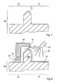
- FIG. 1 is a mold 50 and a section of such a mold 50 shown schematically in a sectional view.
- the molding tool has a rib 54, which of course in the Sectional view is merely made as a protruding tip or a bulge of the mold 50.
- the rib 54 divides the forming tool 50 into a first tool zone 51 and a second tool zone 52.
- FIG. 16 schematically shows how a first surface material 31 (for producing a first surface zone of a piece of equipment to be described later) is applied in the first tool zone 51 by means of an application aid 65.
- the application aid 65 is in particular a spray device or spray device for applying the first surface material 31.
- the second tool zone 52 is covered by means of a tool cover 60.
- particles 66 of the first surface material 31 are effectively prevented from entering the region of the second tooling zone 52.
- This is realized in particular by a special geometry of the rib 54.
- the rib 54 is provided tapering.
- the rib 54 is shaped differently, for example at its tip is provided round or that the tip of the rib 54 in the direction of the first tool zone 51 or toward the second tool zone 52 shifted, ie asymmetrically shaped , is provided.
- a fluid 61 in particular air, flows through between the tool cover 60 and the second tool zone 52 of the mold 50 such that deposition of particles 66 of the first surface material 31 in the region of the second tool zone 52 is prevented.
- a gap 61 to be formed between the tool cover 60 and the rib 54 or, in particular, between the tool cover 60 and the tip of the rib 54, through which the fluid 63 flows. This makes it even more effective (as already by the shape of the rib 54) possible to prevent the deposition of the particles 66.
- the tool cover 60th On the rib 62 facing away from edge 62 and page 62 is the tool cover 60th in particular provided sealed relative to the second tool zone 52 of the mold 50. According to the invention there are openings for the passage of the fluid 63 at this point of the tool cover 60, as indicated in the drawing.
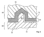
- FIG. 3 is a complete mold comprising the mold and another mold 55 shown schematically in cross section.
- the interior trim part comprises on its visible side 20 (FIG. FIG. 6 ) in a first surface zone 21, the first surface material 31 and in a second surface zone 22, the second surface material 32.
- a groove-shaped recess 24 (FIG. FIG. 5 ) realized in the fitting part 10.
- This groove-shaped recess 24 is of course shaped to be complementary to the rib 54 and, therefore, according to the invention has, in particular, a tapering or tapered or rounded shape.
- the fitting 10 essentially comprises the second surface material 32, which is covered only by the first surface material 31 in the first surface zone 21.
- FIGS. 4 and 5 Further embodiments of the production of the equipment part 10 and the equipment part 10 are given, in which in addition to the first surface material 31 and the second surface material 32, a back side material 33 is present, which in particular at least with respect to the visible side of the equipment part 10 completely covered by the surface materials 31, 32 is.
- the surface materials 31, 32 for realizing the material properties necessary for the fitting 10 on its visible side 20 and, for example, to realize the necessary stability of the fitting 10 or to realize other properties of the fitting 10 - another material that is, the backside material 33 is used, which, for example, can be chosen considerably more cost-effectively than the surface materials 31, 32, in particular also because of this, because the requirements for the backside material 33 may be lower because it may be provided protected by other materials such as from exposure to sunlight or the like.
- the first and second surface materials 31, 32 are provided only in a comparatively narrow overlap area 39 between the first surface zone 21 and the second surface zone 22.
- FIG. 5 is in a further embodiment of the Overlapping area 39 significantly extended provided, namely substantially comprising the complete back of the first surface material 31, similar to in FIG. 3 , But there the reference numeral is not used.
- FIG. 6 schematically a section of the front or visible side 20 of the equipment part 10 is shown, wherein the first surface zone 21, the second surface zone 22 and arranged between these groove-shaped recess 24 can be seen.
- Materials used as surface materials 31, 32 are, in particular, materials which meet the specification requirements (with regard to abrasion, illuminance or light fastness, etc.), in particular on a liquid or powder basis, and which are fixed to one another or to the backing material 33 (also called casting material) ) connect. Preference is given to paint systems based on PUR or acrylic in liquid or solid form, preferably reactive systems.
- the fitting part 10 is provided in particular as an interior fitting part 10 of a motor vehicle, but may also be provided as an exterior fitting part of a motor vehicle or as another injection molding fitting part, for example in the living area or the like.
- the equipment part may be, in particular, a cockpit trim, a door trim, a roof divan trim, a seat trim, a trunk trim, a bumper, or other equipment.
Landscapes
- Engineering & Computer Science (AREA)
- Mechanical Engineering (AREA)
- Vehicle Interior And Exterior Ornaments, Soundproofing, And Insulation (AREA)
- Moulds For Moulding Plastics Or The Like (AREA)
- Automobile Manufacture Line, Endless Track Vehicle, Trailer (AREA)
Abstract
Description
Die vorliegende Erfindung betrifft ein Verfahren zur Herstellung eines wenigstens zwei Oberflächenzonen aufweisenden Ausstattungsteils für ein Kraftfahrzeug, insbesondere ein Innenausstattungsteil, gemäß dem Oberbegriff des Patentanspruchs 1, sowie ein Formwerkzeug gemäß dem Oberbegriff des Patentanspruchs 4.The present invention relates to a method for producing an equipment part having at least two surface zones for a motor vehicle, in particular an interior trim part, according to the preamble of patent claim 1, as well as a mold tool according to the preamble of patent claim 4.
Ein solches Verfahren zur Herstellung eines Ausstattungsteils ist allgemein bekannt. Beispielsweise ist aus der deutschen Patentschrift
Aufgabe der vorliegenden Erfindung ist es, ein Verfahren zur Herstellung eines wenigstens zwei Oberflächenzonen aufweisenden Ausstattungsteils für ein Kraftfahrzeug, insbesondere ein Innenausstattungsteil, zu schaffen, welches eine genaue Abgrenzung zwischen verschiedenen Oberflächenzonen erlaubt und diese Abgrenzung einerseits mit der notwendigen optischen Güte ermöglicht und andererseits ein einfaches, robustes und kostengünstig darzustellendes Herstellungsverfahren bereitstellt.The object of the present invention is to provide a method for producing a fitting comprising at least two surface zones for a motor vehicle, in particular an interior fitting, which allows a precise demarcation between different surface zones and this delimitation on the one hand with the necessary optical quality and on the other hand a simple , provides robust and inexpensive to represent manufacturing process.
Diese Aufgabe wird durch ein Verfahren gemäß Patentanspruch 1 sowie durch ein Formwerkzeug gemäß Patentanspruch 4 gelöst.This object is achieved by a method according to claim 1 and by a mold according to claim 4.
Vorteilhafte weiterbildungen der Erfindung sind Gegenstand der abhängigen Ansprüche 2 und 3. Hierdurch ist es möglich, dass eine genaue Abgrenzung der beiden Oberflächenzonen realisierbar ist, ohne dass es zu optisch unschönen Erscheinungen am Übergang zwischen der ersten und der zweiten Oberflächenzone kommt. Herkömmlicherweise führt ein sogenannter "Bridging-Effekt" dazu, dass bei einer Abdeckung der zweiten Oberflächenzone durch eine Werkzeugabdeckung, die in Kontakt mit dem ersten Oberflächenmaterial steht, beim Abnehmen der Werkzeugabdeckung ein unschönes Abreißen des ersten Oberflächen materials wahrscheinlich ist. Mit dem erfindungsgemäßen Verfahren ist daher eine deutlich sauberere Trennlinie zwischen der ersten und der zweiten Oberflächenzone bei dem Innenausstattungsteil möglich.Advantageous further developments of the invention are subject matter of the dependent claims 2 and 3. This makes it possible that a precise delimitation of the two surface zones can be realized, without causing visually ugly phenomena at the transition between the first and the second surface zone comes. Conventionally, a so-called "bridging effect" results in that when the second surface zone is covered by a tool cover which is in contact with the first surface material, unpleasant tearing off of the first surface material is likely when the tool cover is removed. With the method according to the invention, therefore, a significantly cleaner separation line between the first and the second surface zone in the interior fitting part is possible.
Erfindungsgemäß ist ferner vorgesehen, dass zwischen der Werkzeugabdeckung und der Rippe ein Spalt vorgesehen ist, durch den während des Aufbringens des ersten Oberflächenmaterials ein Fluid, insbesondere Luft, ströme. Hierdurch wird die Wahrscheinlichkeit des bereits angesprochenen "Brtdging-Effekts" weiter reduziert und ferner eine noch bessere Abtrennung der verschiedenen Oberflächenzonen dadurch ermöglicht, dass Materialtropfen bzw. Materialpartikel des ersten Oberflächenmaterials, welches beispielsweise mittels eines Sprühverfahrens aufgebracht wird, jedenfalls nicht in den Bereich der zweiten Oberflächenzone gelangen kann.According to the invention, it is further provided that a gap is provided between the tool cover and the rib, through which a fluid, in particular air, flows during the application of the first surface material. In this way, the probability of the already mentioned "Brtdging effect" is further reduced and further allows an even better separation of the different surface zones, that material drops or material particles of the first surface material, which is applied for example by means of a spraying process, at least not in the range of the second Surface zone can get.
Erfindungsgemäß ist vorgesehen, dass die Werkzeugabdeckung (Maske) an ihrer der Rippe abgewandten Kante gegenüber dem Formwerkzeug abgedichtet wird. Hierdurch ist es mit einfachen Mitteln möglich, das Herstellungsverfahren kostengünstig zu halten, weil lediglich ein geringer Druck des zwischen der Werkzeugabdeckung und der Rippe durchströmenden Fluids notwendig ist.According to the invention it is provided that the tool cover (mask) is sealed at its edge facing away from the rib with respect to the mold. As a result, it is possible by simple means to keep the manufacturing process cost, because only a small pressure of the flowing between the tool cover and the rib fluid is necessary.
Ferner ist bevorzugt, dass nach dem Aufbringen des ersten Oberflächenmaterials und einer Entfernung der Werkzeugabdeckung ein zweites Oberflächenmaterial in der zweiten Werkzeugzone und im Bereich der Rippe aufgebracht wird. Hierdurch ist es nach dem Aufbringen des ersten Obertlächenmaterials sehr einfach möglich, die zweite bzw. generell eine weitere Oberflächenzone des Ausstattungsteils hinsichtlich seiner Oberfläche mit dem zweiten Oberflächenmaterial zu gestalten. Weiterhin wird dadurch eine gute Verbindung zwischen dem ersten Oberflächenmaterial und dem zweiten Oberflächenmaterial an der Stelle der Rippe ermöglicht, so dass das Innenausstattungsteil an der Grenzfläche zwischen dem ersten Oberflächen material und dem zweiten Oberflächen material nicht geschwächt ist.Furthermore, it is preferred that, after the application of the first surface material and removal of the tool cover, a second surface material is applied in the second tool zone and in the region of the rib. As a result, after the application of the first surface material, it is very easy to design the second or generally another surface zone of the equipment with respect to its surface with the second surface material. Furthermore, thereby a good connection between the first surface material and the second surface material at the location of the rib is made possible, so that the interior fitting material at the interface between the first surface material and the second surface material is not weakened.
Ein weiterer Gegenstand der vorliegenden Erfindung ist ein Formwerkzeug gemäß Patentanspruch 4.Another object of the present invention is a mold according to claim 4.
Hierdurch ist es mit einfachen Mitteln möglich, das erfindungsgemäße Herstellungsverfahren für ein Ausstattungsteil durchzuführen und eine saubere Trennung zwischen den Oberflächenzonen zu erreichen. Unter einer spitz zulaufenden Form wird erfindungsgemäß insbesondere eine mittige Spitze, bezogen auf die Ränder der Rippe, verstanden. Eine zum einen oder dem anderen Rand verschobene Spitze ist jedoch alternativ oder lediglich in Teilbereichen auch möglich. Unter einer stumpf zulaufenden Form wird erfindungsgemäß insbesondere eine oben flache Rippe verstanden. Unter rund zulaufenden Form wird erfindungsgemäß insbesondere eine oben abgerundete, d.h. im wesentlichen halbkreisförmige. Rippe verstanden.As a result, it is possible with simple means to carry out the production method according to the invention for a piece of equipment and to achieve a clean separation between the surface zones. Under a tapered shape according to the invention, in particular a central tip, based on the edges of the rib understood. However, a tip shifted to one or the other edge is alternatively or only partially possible. Under a truncated shape is understood in particular a top flat rib according to the invention. Under a tapered shape according to the invention, in particular, a top-rounded, i. essentially semicircular. Rib understood.
Ausführungsbeispiele der Erfindung sind in den Zeichnungen dargestellt und in der nachfolgenden Beschreibung näher erläutert.
- Figur 1
- zeigt schematisch eine Schnittdarstellung durch ein Formwerkzeug mit einer ersten und einer zweiten Werkzeugzone,
- Figur 2
- eine schematische Schnittdarstellung durch das Formwerkzeug während des Aufbringens eines ersten Oberflächenmatenais in der ersten Werkzeugzone,
- Figur 3, 4 und 5
- zeigen schematisch die Herstellung verschiedener Ausführungsformen eines Ausstattungsteils mittels dem Formwerkzeug und einem weiteren Formwerkzeug und
- Figur 6
- zeigt schematisch einen Teil der Sichtseite eines erfindungsgemäßen Ausstattungsteils.
- FIG. 1
- schematically shows a sectional view through a mold with a first and a second tool zone,
- FIG. 2
- a schematic sectional view through the mold during the application of a first Oberflächenmatenais in the first tool zone,
- FIGS. 3, 4 and 5
- show schematically the production of various embodiments of a piece of equipment by means of the molding tool and another mold and
- FIG. 6
- schematically shows a part of the visible side of a piece of equipment according to the invention.
In
In
Während des Aufbringens des ersten Oberflächenmaterials 31 in die erste Werkzeugzone 51 wird die zweite Werkzeugzone 52 mittels einer Werkzeugabdeckung 60 abgedeckt. Hierdurch werden (schematisch mittels flugbahnartigen Strichen in
Besonders vorteilhaft ist es, dass ein Fluid 61, insbesondere Luft, zwischen der Werkzeugabdeckung 60 und der zweiten Werkzeugzone 52 des Formwerkzeugs 50 derart hindurchströmt, dass eine Ablagerung von Teilchen 66 des ersten Oberflächenmaterials 31 im Bereich der zweiten Werkzeugzone 52 verhindert wird. Hierzu ist insbesondere vorgesehen, dass zwischen der Werkzeugabdeckung 60 und der Rippe 54 bzw, insbesondere zwischen der Werkzeugabdeckung 60 und der Spitze der Rippe 54 ein Spalt 61 gebildet ist, durch den das Fluid 63 hindurchströmt. Hierdurch ist es noch effektiver (als bereits durch die Formgebung der Rippe 54) möglich, die Ablagerung der Teilchen 66 zu verhindern. Auf der der Rippe 54 abgewandten Kante 62 bzw. Seite 62 ist die Werkzeugabdeckung 60 insbesondere gegenüber der zweiten Werkzeugszone 52 des Formwerkzeuges 50 abgedichtet vorgesehen. Erfindungsgemäß sind dort Öffnungen zur Durchleitung des Fluids 63 an dieser Stelle der Werkzeugabdeckung 60 vorhanden, wie in der Zeichnung angedeutet.It is particularly advantageous that a
In
In den
In
Zum Einsatz kommen als Oberflächenmaterialien 31, 32 insbesondere Materialien, die den Spezifikationsanforderungen (hinsichtlich Abrieb, Beleuchtungsfestigkeit bzw. Lichtechtheit, etc.) genügen, insbesondere auf flüssiger oder pulverförmiger Basis, und die sich fest miteinander bzw. mit dem Rückseitenmaterial 33 (auch Gießmaterial genannt) verbinden. Bevorzugt sind Lacksysteme auf PUR oder Acrylbasis in flüssiger oder fester Form, bevorzugt reagierende Systeme.
Das Ausstattungsteil 10 ist insbesondere als Innenausstattungsteil 10 eines Kraftfahrzeugs vorgesehen, kann jedoch auch als ein Außenausstattungsteil eines Kraftfahrzeugs oder als ein sonstiges Spritzgussausstattungsteil, beispielsweise im Wohnbereich oder dergleichen, vorgesehen sein. Hierbei kann es sich bei dem Ausstattungsteil insbesondere um eine Cockpitverkleidung, eine Türverkleidung, eine Dachhimmeiverkleidung, eine Sitzverkleidung, eine Kofferraumverkleidung, eine Stoßstange, oder sonstige Ausstattungsteile handeln.Materials used as
The
- 1010
- Ausstattungsteilpiece of equipment
- 2020
- SichtseiteMain page
- 2121
- erste Oberflächenzonefirst surface zone
- 2222
- zweite Oberflächenzonesecond surface zone
- 2424
- Ausnehmungrecess
- 3131
- erstes Oberflächenmaterialfirst surface material
- 3232
- zweites Oberflächenmaterialsecond surface material
- 3333
- RückseitenmaterialBack material
- 3939
- Überlappbereichoverlap
- 5050
- Formwerkzeugmold
- 5151
- erste Werkzeugzonefirst tool zone
- 5252
- zweite Werkzeugzonesecond tool zone
- 5454
- Ripperib
- 5555
- weiteres Formwerkzeuganother mold
- 6060
- Werkzeugabdeckungtool cover
- 6161
- Spaltgap
- 6262
- Kanteedge
- 6363
- Fluid, insbesondere LuftFluid, especially air
- 6565
- Aufbringungshilfsmittelapplication aids
- 6666
- Teilchen bzw. Partikel des ersten OberflächenmaterialsParticles or particles of the first surface material
Claims (4)
- Method for producing a piece of trim (10) intended for a motor vehicle and comprising at least two surface zones (21, 22), in particular a piece of interior trim (10), wherein a mould (50) has a first mould zone (51), corresponding to the first surface zone (21), and a second mould zone (52), corresponding to the second surface zone (22), wherein the mould (50) has a rib (54) between the first mould zone (51) and the second mould zone (52), wherein a first surface material (31) is applied to the mould (50) in the first mould zone (51) and wherein the second mould zone (52) is covered at least in the region along the rib (54) by means of a mould cover (60) during the application of the first surface material (31), characterized in that a gap (61) through which a fluid, in particular air, flows during the application of the first surface material (31) is provided between the mould cover (60) and the rib (54), wherein the mould cover (60) is sealed with respect to the mould (50) at the edge (62) of said cover that is facing away from the rib (54) and has openings there through which the fluid (63) is passed.
- Method according to Claim 1, characterized in that, after the application of the first surface material (31) and removal of the mould cover (60), a second surface material (32) is applied in the second mould zone (52) and in the region of the rib (54).
- Method according to one of the preceding claims, characterized in that either a rear-side material (33) is applied to the first and second surface materials (31, 32) or the second surface material (32) is applied to the first surface material (31) by means of a further mould (55), which together with the mould (50) forms a substantially closed casting mould.
- Mould (50) for producing a piece of trim (10) intended for a motor vehicle and comprising at least two surface zones (21, 22), in particular a piece of interior trim (10), wherein the mould (50) has a first mould zone (51), corresponding to the first surface zone (21), and a second mould zone (52), corresponding to the second surface zone (22), wherein the mould (50) also has a rib (54) between the first mould zone (51) and the second mould zone (52), the rib being provided such that it substantially tapers to a point in cross section, characterized in that a gap (61) through which a fluid, in particular air, flows during the application of the first surface material (31) is provided between the mould cover (60) and the rib (54), wherein the mould cover (60) is sealed with respect to the mould (50) at the edge (62) of said cover that is facing away from the rib (54) and has openings there through which the fluid (63) passes.
Applications Claiming Priority (2)
| Application Number | Priority Date | Filing Date | Title |
|---|---|---|---|
| DE102005058591A DE102005058591A1 (en) | 2005-12-07 | 2005-12-07 | Method for producing a display part having at least two surface zones for a motor vehicle, mold and fitting for a motor vehicle |
| PCT/EP2006/011534 WO2007065600A1 (en) | 2005-12-07 | 2006-12-01 | Method for the production of a piece of motor vehicle equipment comprising at least two surface zones, form tool, and piece of motor vehicle equipment |
Publications (2)
| Publication Number | Publication Date |
|---|---|
| EP1960176A1 EP1960176A1 (en) | 2008-08-27 |
| EP1960176B1 true EP1960176B1 (en) | 2010-09-29 |
Family
ID=37897312
Family Applications (1)
| Application Number | Title | Priority Date | Filing Date |
|---|---|---|---|
| EP06829225A Not-in-force EP1960176B1 (en) | 2005-12-07 | 2006-12-01 | Method for the production of a piece of motor vehicle equipment comprising at least two surface zones and form tool |
Country Status (4)
| Country | Link |
|---|---|
| EP (1) | EP1960176B1 (en) |
| AT (1) | ATE482810T1 (en) |
| DE (2) | DE102005058591A1 (en) |
| WO (1) | WO2007065600A1 (en) |
Families Citing this family (4)
| Publication number | Priority date | Publication date | Assignee | Title |
|---|---|---|---|---|
| DE102008002405A1 (en) * | 2008-06-12 | 2009-12-17 | Volkswagen Ag | Two or multicolored molded part e.g. sluch skin, manufacturing method for motor vehicle, involves inserting limiting device for limiting of prestage part into mold before molding process, and removing part of device after molding process |
| DE102008032279B4 (en) | 2008-07-09 | 2017-12-21 | Bayerische Motoren Werke Aktiengesellschaft | Color separation mask and device for covering a mold and method for introducing two different spray paints in a mold |
| DE102011119742A1 (en) * | 2011-11-29 | 2013-05-29 | Faurecia Innenraum Systeme Gmbh | Method for manufacturing multi-layer liner part that is utilized for lining dashboard of motor car, involves filling closed tools with material such that material is bonded with another material, and curing former material at liner part |
| DE102011119743A1 (en) * | 2011-11-29 | 2013-05-29 | Faurecia Innenraum Systeme Gmbh | Method for producing multilayer inner lining part for motor vehicle, involves forming material layer by coating inner surface section of contour-shaped inner surface of mold half of mold with material |
Family Cites Families (14)
| Publication number | Priority date | Publication date | Assignee | Title |
|---|---|---|---|---|
| US4562025A (en) * | 1984-05-25 | 1985-12-31 | Ex-Cell-O Corporation | Mold method and apparatus for multi-color plastic shells |
| US4940012A (en) * | 1986-12-23 | 1990-07-10 | Nordson Corporation | Mold coating apparatus with air flow control numbers |
| JP2686791B2 (en) * | 1988-11-22 | 1997-12-08 | 株式会社イノアックコーポレーション | Method for producing different color epidermis |
| DE3911485C1 (en) * | 1989-04-08 | 1990-11-08 | Deutsche Fibrit Gesellschaft Ebers & Dr. Mueller Mbh, 4150 Krefeld, De | |
| DE3919723A1 (en) * | 1989-06-16 | 1991-01-10 | Ebers & Mueller Fibrit | Varnishing of instrument panel of motor vehicle - by using mask with air flow from under mask edges |
| DE4029254A1 (en) * | 1990-09-14 | 1992-03-19 | Benecke Ag J H | METHOD FOR PRODUCING MULTICOLORED SLUSH SKINS AND FORM AND SEPARATING DEVICE FOR CARRYING OUT THE METHOD |
| BE1005821A3 (en) * | 1992-05-18 | 1994-02-08 | Recticel | PROCESS FOR THE PRODUCTION OF SELF-SUPPORTING APPETIZERS PLASTIC PARTS AND THUS MANUFACTURED trim part. |
| EP0804327B1 (en) * | 1994-06-01 | 2001-09-19 | Recticel | Method and spray mould assembly for manufacturing an elastomeric skin of at least two elastomeric materials and such elastomeric skin |
| EP0972625A1 (en) * | 1998-07-13 | 2000-01-19 | Ecia - Equipements Et Composants Pour L'industrie Automobile | Apparatus for manufacturing a plastic skin cover for a vehicle equipment part |
| DE10004735A1 (en) * | 2000-01-28 | 2001-08-02 | Volkswagen Ag | Method and device for producing a molded plastic part and molded plastic part |
| US6524509B1 (en) * | 2000-08-16 | 2003-02-25 | Textron Automotive Company Inc. | Method for casting multicolored parts for automotive interior applications |
| DE10062825B4 (en) * | 2000-12-15 | 2004-11-04 | Basf Ag | Process and molding tool for the production of molded parts, in particular for automotive interior trim |
| DE10305688A1 (en) * | 2003-02-12 | 2004-11-11 | Volkswagen Ag | High quality finish multi-colored vehicle component production method involves joining parts of different color along a seam |
| DE102005020492A1 (en) * | 2005-04-29 | 2006-11-02 | Benecke-Kaliko Ag | Device for producing multicolored plastic molded skins |
-
2005
- 2005-12-07 DE DE102005058591A patent/DE102005058591A1/en not_active Withdrawn
-
2006
- 2006-12-01 EP EP06829225A patent/EP1960176B1/en not_active Not-in-force
- 2006-12-01 AT AT06829225T patent/ATE482810T1/en active
- 2006-12-01 DE DE502006007990T patent/DE502006007990D1/en active Active
- 2006-12-01 WO PCT/EP2006/011534 patent/WO2007065600A1/en active Application Filing
Also Published As
| Publication number | Publication date |
|---|---|
| EP1960176A1 (en) | 2008-08-27 |
| ATE482810T1 (en) | 2010-10-15 |
| WO2007065600A1 (en) | 2007-06-14 |
| DE502006007990D1 (en) | 2010-11-11 |
| DE102005058591A1 (en) | 2007-06-14 |
Similar Documents
| Publication | Publication Date | Title |
|---|---|---|
| DE19961706A1 (en) | Connection of a vehicle window to an adjacent component | |
| DE102007041479A1 (en) | One-piece lock holder | |
| EP2011723A2 (en) | Aerodynamic spoiler for a motor vehicle | |
| WO2004039619A1 (en) | Sealing billet for bodywork seals with a partially reinforced sealing profile section | |
| EP1960176B1 (en) | Method for the production of a piece of motor vehicle equipment comprising at least two surface zones and form tool | |
| EP2310231B1 (en) | Profiled decorative moulding, in particular for the window area of a motor vehicle | |
| WO2011138390A1 (en) | Bushing and method for producing such a bushing | |
| DE69201035T2 (en) | Motor vehicle glazing installed from the inside. | |
| DE10336187A1 (en) | Hybrid component and associated manufacturing method | |
| EP2300270B1 (en) | Accessory for a vehicle and method for producing an accessory | |
| EP1920899A1 (en) | Method for manufacturing plastic hybrid components, corresponding tool and use of such a tool | |
| EP2088016B1 (en) | Sliding window assembly for automotive vehicle | |
| EP3325298B1 (en) | Extruded sealing strip with venting openings | |
| DE102007041982A1 (en) | Manufacturing vehicle internal door-pull handle as hollow body coated with soft plastic, employs water injection process to form hollow cavity in injection-molding | |
| DE3642428A1 (en) | VEHICLE WITH VEHICLE DOOR AND DOOR SEAL | |
| DE102012206767A1 (en) | Windscreen for motor vehicle i.e. passenger car, has lateral edge area whose outer side is provided with interruption structure comprising interruption element forming surface structure element in outer side of lateral edge area | |
| DE102012023269A1 (en) | Exterior mirror assembly for a motor vehicle | |
| DE102006025647B4 (en) | airbag cover | |
| DE19609747C2 (en) | Car glass pane prepared for adhesive assembly and process for its production | |
| DE19721566B4 (en) | Method for producing a disk body with a frame made of soft elastic material molded by encapsulation | |
| DE102007015466A1 (en) | Method for producing a sealing arrangement, in particular for a motor vehicle, with a sealing element and a carrier and such a sealing arrangement | |
| EP2394859B1 (en) | Cladding assembly for a motor vehicle | |
| EP0716964A1 (en) | Attachment element for a windscreen wiper, as well as method and apparatus for its manufacture | |
| DE102018126276A1 (en) | EMBLEM COMPONENT, AIRBAG MODULE COVER WITH SUCH A EMBLEM COMPONENT AND METHOD FOR PRODUCING AN EMBLEM COMPONENT | |
| DE102017004456A1 (en) | A seal assembly for a vehicle pillar and method of making such a seal assembly |
Legal Events
| Date | Code | Title | Description |
|---|---|---|---|
| PUAI | Public reference made under article 153(3) epc to a published international application that has entered the european phase |
Free format text: ORIGINAL CODE: 0009012 |
|
| 17P | Request for examination filed |
Effective date: 20080707 |
|
| AK | Designated contracting states |
Kind code of ref document: A1 Designated state(s): AT BE BG CH CY CZ DE DK EE ES FI FR GB GR HU IE IS IT LI LT LU LV MC NL PL PT RO SE SI SK TR |
|
| RIN1 | Information on inventor provided before grant (corrected) |
Inventor name: CEMPULIK, PETER Inventor name: BOGDANOV, NATALIE Inventor name: BRUECKNER, HUBERT Inventor name: HENDRIX, JOERG |
|
| 17Q | First examination report despatched |
Effective date: 20081001 |
|
| RTI1 | Title (correction) |
Free format text: METHOD FOR THE PRODUCTION OF A PIECE OF MOTOR VEHICLE EQUIPMENT COMPRISING AT LEAST TWO SURFACE ZONES AND FORM TOOL |
|
| GRAP | Despatch of communication of intention to grant a patent |
Free format text: ORIGINAL CODE: EPIDOSNIGR1 |
|
| GRAS | Grant fee paid |
Free format text: ORIGINAL CODE: EPIDOSNIGR3 |
|
| GRAA | (expected) grant |
Free format text: ORIGINAL CODE: 0009210 |
|
| AK | Designated contracting states |
Kind code of ref document: B1 Designated state(s): AT BE BG CH CY CZ DE DK EE ES FI FR GB GR HU IE IS IT LI LT LU LV MC NL PL PT RO SE SI SK TR |
|
| REG | Reference to a national code |
Ref country code: GB Ref legal event code: FG4D Free format text: NOT ENGLISH |
|
| REG | Reference to a national code |
Ref country code: CH Ref legal event code: EP |
|
| REG | Reference to a national code |
Ref country code: IE Ref legal event code: FG4D Free format text: LANGUAGE OF EP DOCUMENT: GERMAN |
|
| REF | Corresponds to: |
Ref document number: 502006007990 Country of ref document: DE Date of ref document: 20101111 Kind code of ref document: P |
|
| PG25 | Lapsed in a contracting state [announced via postgrant information from national office to epo] |
Ref country code: LT Free format text: LAPSE BECAUSE OF FAILURE TO SUBMIT A TRANSLATION OF THE DESCRIPTION OR TO PAY THE FEE WITHIN THE PRESCRIBED TIME-LIMIT Effective date: 20100929 Ref country code: FI Free format text: LAPSE BECAUSE OF FAILURE TO SUBMIT A TRANSLATION OF THE DESCRIPTION OR TO PAY THE FEE WITHIN THE PRESCRIBED TIME-LIMIT Effective date: 20100929 |
|
| PGFP | Annual fee paid to national office [announced via postgrant information from national office to epo] |
Ref country code: FR Payment date: 20110104 Year of fee payment: 5 |
|
| REG | Reference to a national code |
Ref country code: NL Ref legal event code: VDEP Effective date: 20100929 |
|
| LTIE | Lt: invalidation of european patent or patent extension |
Effective date: 20100929 |
|
| PG25 | Lapsed in a contracting state [announced via postgrant information from national office to epo] |
Ref country code: SI Free format text: LAPSE BECAUSE OF FAILURE TO SUBMIT A TRANSLATION OF THE DESCRIPTION OR TO PAY THE FEE WITHIN THE PRESCRIBED TIME-LIMIT Effective date: 20100929 |
|
| PG25 | Lapsed in a contracting state [announced via postgrant information from national office to epo] |
Ref country code: SE Free format text: LAPSE BECAUSE OF FAILURE TO SUBMIT A TRANSLATION OF THE DESCRIPTION OR TO PAY THE FEE WITHIN THE PRESCRIBED TIME-LIMIT Effective date: 20100929 Ref country code: LV Free format text: LAPSE BECAUSE OF FAILURE TO SUBMIT A TRANSLATION OF THE DESCRIPTION OR TO PAY THE FEE WITHIN THE PRESCRIBED TIME-LIMIT Effective date: 20100929 Ref country code: GR Free format text: LAPSE BECAUSE OF FAILURE TO SUBMIT A TRANSLATION OF THE DESCRIPTION OR TO PAY THE FEE WITHIN THE PRESCRIBED TIME-LIMIT Effective date: 20101230 |
|
| PGFP | Annual fee paid to national office [announced via postgrant information from national office to epo] |
Ref country code: GB Payment date: 20101221 Year of fee payment: 5 |
|
| REG | Reference to a national code |
Ref country code: IE Ref legal event code: FD4D |
|
| PG25 | Lapsed in a contracting state [announced via postgrant information from national office to epo] |
Ref country code: IT Free format text: LAPSE BECAUSE OF FAILURE TO SUBMIT A TRANSLATION OF THE DESCRIPTION OR TO PAY THE FEE WITHIN THE PRESCRIBED TIME-LIMIT Effective date: 20100929 Ref country code: IS Free format text: LAPSE BECAUSE OF FAILURE TO SUBMIT A TRANSLATION OF THE DESCRIPTION OR TO PAY THE FEE WITHIN THE PRESCRIBED TIME-LIMIT Effective date: 20110129 Ref country code: EE Free format text: LAPSE BECAUSE OF FAILURE TO SUBMIT A TRANSLATION OF THE DESCRIPTION OR TO PAY THE FEE WITHIN THE PRESCRIBED TIME-LIMIT Effective date: 20100929 Ref country code: RO Free format text: LAPSE BECAUSE OF FAILURE TO SUBMIT A TRANSLATION OF THE DESCRIPTION OR TO PAY THE FEE WITHIN THE PRESCRIBED TIME-LIMIT Effective date: 20100929 Ref country code: PT Free format text: LAPSE BECAUSE OF FAILURE TO SUBMIT A TRANSLATION OF THE DESCRIPTION OR TO PAY THE FEE WITHIN THE PRESCRIBED TIME-LIMIT Effective date: 20110131 Ref country code: SK Free format text: LAPSE BECAUSE OF FAILURE TO SUBMIT A TRANSLATION OF THE DESCRIPTION OR TO PAY THE FEE WITHIN THE PRESCRIBED TIME-LIMIT Effective date: 20100929 Ref country code: NL Free format text: LAPSE BECAUSE OF FAILURE TO SUBMIT A TRANSLATION OF THE DESCRIPTION OR TO PAY THE FEE WITHIN THE PRESCRIBED TIME-LIMIT Effective date: 20100929 Ref country code: CZ Free format text: LAPSE BECAUSE OF FAILURE TO SUBMIT A TRANSLATION OF THE DESCRIPTION OR TO PAY THE FEE WITHIN THE PRESCRIBED TIME-LIMIT Effective date: 20100929 |
|
| PGFP | Annual fee paid to national office [announced via postgrant information from national office to epo] |
Ref country code: DE Payment date: 20101231 Year of fee payment: 5 |
|
| BERE | Be: lapsed |
Owner name: JOHNSON CONTROLS INTERIORS G.M.B.H. & CO. KG Effective date: 20101231 |
|
| PG25 | Lapsed in a contracting state [announced via postgrant information from national office to epo] |
Ref country code: MC Free format text: LAPSE BECAUSE OF NON-PAYMENT OF DUE FEES Effective date: 20101231 Ref country code: ES Free format text: LAPSE BECAUSE OF FAILURE TO SUBMIT A TRANSLATION OF THE DESCRIPTION OR TO PAY THE FEE WITHIN THE PRESCRIBED TIME-LIMIT Effective date: 20110109 Ref country code: IE Free format text: LAPSE BECAUSE OF FAILURE TO SUBMIT A TRANSLATION OF THE DESCRIPTION OR TO PAY THE FEE WITHIN THE PRESCRIBED TIME-LIMIT Effective date: 20100929 |
|
| REG | Reference to a national code |
Ref country code: CH Ref legal event code: PL |
|
| PLBE | No opposition filed within time limit |
Free format text: ORIGINAL CODE: 0009261 |
|
| STAA | Information on the status of an ep patent application or granted ep patent |
Free format text: STATUS: NO OPPOSITION FILED WITHIN TIME LIMIT |
|
| PG25 | Lapsed in a contracting state [announced via postgrant information from national office to epo] |
Ref country code: DK Free format text: LAPSE BECAUSE OF FAILURE TO SUBMIT A TRANSLATION OF THE DESCRIPTION OR TO PAY THE FEE WITHIN THE PRESCRIBED TIME-LIMIT Effective date: 20100929 Ref country code: PL Free format text: LAPSE BECAUSE OF FAILURE TO SUBMIT A TRANSLATION OF THE DESCRIPTION OR TO PAY THE FEE WITHIN THE PRESCRIBED TIME-LIMIT Effective date: 20100929 |
|
| PG25 | Lapsed in a contracting state [announced via postgrant information from national office to epo] |
Ref country code: BE Free format text: LAPSE BECAUSE OF NON-PAYMENT OF DUE FEES Effective date: 20101231 |
|
| REG | Reference to a national code |
Ref country code: DE Ref legal event code: R097 Ref document number: 502006007990 Country of ref document: DE Effective date: 20110630 |
|
| PG25 | Lapsed in a contracting state [announced via postgrant information from national office to epo] |
Ref country code: LI Free format text: LAPSE BECAUSE OF NON-PAYMENT OF DUE FEES Effective date: 20101231 Ref country code: CH Free format text: LAPSE BECAUSE OF NON-PAYMENT OF DUE FEES Effective date: 20101231 |
|
| GBPC | Gb: european patent ceased through non-payment of renewal fee |
Effective date: 20111201 |
|
| PG25 | Lapsed in a contracting state [announced via postgrant information from national office to epo] |
Ref country code: CY Free format text: LAPSE BECAUSE OF FAILURE TO SUBMIT A TRANSLATION OF THE DESCRIPTION OR TO PAY THE FEE WITHIN THE PRESCRIBED TIME-LIMIT Effective date: 20100929 |
|
| REG | Reference to a national code |
Ref country code: FR Ref legal event code: ST Effective date: 20120831 |
|
| PG25 | Lapsed in a contracting state [announced via postgrant information from national office to epo] |
Ref country code: LU Free format text: LAPSE BECAUSE OF NON-PAYMENT OF DUE FEES Effective date: 20101201 Ref country code: BG Free format text: LAPSE BECAUSE OF FAILURE TO SUBMIT A TRANSLATION OF THE DESCRIPTION OR TO PAY THE FEE WITHIN THE PRESCRIBED TIME-LIMIT Effective date: 20100929 Ref country code: HU Free format text: LAPSE BECAUSE OF FAILURE TO SUBMIT A TRANSLATION OF THE DESCRIPTION OR TO PAY THE FEE WITHIN THE PRESCRIBED TIME-LIMIT Effective date: 20110330 |
|
| REG | Reference to a national code |
Ref country code: DE Ref legal event code: R119 Ref document number: 502006007990 Country of ref document: DE Effective date: 20120703 |
|
| PG25 | Lapsed in a contracting state [announced via postgrant information from national office to epo] |
Ref country code: DE Free format text: LAPSE BECAUSE OF NON-PAYMENT OF DUE FEES Effective date: 20120703 Ref country code: GB Free format text: LAPSE BECAUSE OF NON-PAYMENT OF DUE FEES Effective date: 20111201 Ref country code: TR Free format text: LAPSE BECAUSE OF FAILURE TO SUBMIT A TRANSLATION OF THE DESCRIPTION OR TO PAY THE FEE WITHIN THE PRESCRIBED TIME-LIMIT Effective date: 20100929 |
|
| REG | Reference to a national code |
Ref country code: AT Ref legal event code: MM01 Ref document number: 482810 Country of ref document: AT Kind code of ref document: T Effective date: 20111201 |
|
| PG25 | Lapsed in a contracting state [announced via postgrant information from national office to epo] |
Ref country code: FR Free format text: LAPSE BECAUSE OF NON-PAYMENT OF DUE FEES Effective date: 20120102 |
|
| PG25 | Lapsed in a contracting state [announced via postgrant information from national office to epo] |
Ref country code: AT Free format text: LAPSE BECAUSE OF NON-PAYMENT OF DUE FEES Effective date: 20111201 |
|
| PG25 | Lapsed in a contracting state [announced via postgrant information from national office to epo] |
Ref country code: BG Free format text: LAPSE BECAUSE OF FAILURE TO SUBMIT A TRANSLATION OF THE DESCRIPTION OR TO PAY THE FEE WITHIN THE PRESCRIBED TIME-LIMIT Effective date: 20101229 |
|
| REG | Reference to a national code |
Ref country code: DE Ref legal event code: R082 Ref document number: 502006007990 Country of ref document: DE |