EP1959552B1 - Procédé et dispositif destinés au fonctionnement d'une machine électrique - Google Patents
Procédé et dispositif destinés au fonctionnement d'une machine électrique Download PDFInfo
- Publication number
- EP1959552B1 EP1959552B1 EP20080100841 EP08100841A EP1959552B1 EP 1959552 B1 EP1959552 B1 EP 1959552B1 EP 20080100841 EP20080100841 EP 20080100841 EP 08100841 A EP08100841 A EP 08100841A EP 1959552 B1 EP1959552 B1 EP 1959552B1
- Authority
- EP
- European Patent Office
- Prior art keywords
- real
- power
- determined
- electrical machine
- control apparatus
- Prior art date
- Legal status (The legal status is an assumption and is not a legal conclusion. Google has not performed a legal analysis and makes no representation as to the accuracy of the status listed.)
- Ceased
Links
Images


Classifications
-
- H—ELECTRICITY
- H02—GENERATION; CONVERSION OR DISTRIBUTION OF ELECTRIC POWER
- H02P—CONTROL OR REGULATION OF ELECTRIC MOTORS, ELECTRIC GENERATORS OR DYNAMO-ELECTRIC CONVERTERS; CONTROLLING TRANSFORMERS, REACTORS OR CHOKE COILS
- H02P23/00—Arrangements or methods for the control of AC motors characterised by a control method other than vector control
- H02P23/12—Observer control, e.g. using Luenberger observers or Kalman filters
-
- B—PERFORMING OPERATIONS; TRANSPORTING
- B62—LAND VEHICLES FOR TRAVELLING OTHERWISE THAN ON RAILS
- B62D—MOTOR VEHICLES; TRAILERS
- B62D5/00—Power-assisted or power-driven steering
- B62D5/04—Power-assisted or power-driven steering electrical, e.g. using an electric servo-motor connected to, or forming part of, the steering gear
- B62D5/0457—Power-assisted or power-driven steering electrical, e.g. using an electric servo-motor connected to, or forming part of, the steering gear characterised by control features of the drive means as such
- B62D5/046—Controlling the motor
-
- B—PERFORMING OPERATIONS; TRANSPORTING
- B62—LAND VEHICLES FOR TRAVELLING OTHERWISE THAN ON RAILS
- B62D—MOTOR VEHICLES; TRAILERS
- B62D5/00—Power-assisted or power-driven steering
- B62D5/04—Power-assisted or power-driven steering electrical, e.g. using an electric servo-motor connected to, or forming part of, the steering gear
- B62D5/0457—Power-assisted or power-driven steering electrical, e.g. using an electric servo-motor connected to, or forming part of, the steering gear characterised by control features of the drive means as such
- B62D5/0481—Power-assisted or power-driven steering electrical, e.g. using an electric servo-motor connected to, or forming part of, the steering gear characterised by control features of the drive means as such monitoring the steering system, e.g. failures
- B62D5/0496—Power-assisted or power-driven steering electrical, e.g. using an electric servo-motor connected to, or forming part of, the steering gear characterised by control features of the drive means as such monitoring the steering system, e.g. failures by using a temperature sensor
-
- H—ELECTRICITY
- H02—GENERATION; CONVERSION OR DISTRIBUTION OF ELECTRIC POWER
- H02P—CONTROL OR REGULATION OF ELECTRIC MOTORS, ELECTRIC GENERATORS OR DYNAMO-ELECTRIC CONVERTERS; CONTROLLING TRANSFORMERS, REACTORS OR CHOKE COILS
- H02P2205/00—Indexing scheme relating to controlling arrangements characterised by the control loops
- H02P2205/03—Power loop, i.e. comparison of the motor power with a power reference
-
- H—ELECTRICITY
- H02—GENERATION; CONVERSION OR DISTRIBUTION OF ELECTRIC POWER
- H02P—CONTROL OR REGULATION OF ELECTRIC MOTORS, ELECTRIC GENERATORS OR DYNAMO-ELECTRIC CONVERTERS; CONTROLLING TRANSFORMERS, REACTORS OR CHOKE COILS
- H02P2207/00—Indexing scheme relating to controlling arrangements characterised by the type of motor
- H02P2207/05—Synchronous machines, e.g. with permanent magnets or DC excitation
Definitions
- the invention relates to a method and a device for operating an electrical machine.
- Electric machines can be used both in an engine operation and in a generator operation.
- synchronous machines are known with a stator, the three winding strands are assigned, and a rotor.
- Synchronous machines are used in the field of automotive technology, where they are used for example for steering systems of motor vehicles. Synchronous machines can be designed with permanent magnets on the rotor. However, they can also be equipped with exciter windings in the rotor. Synchronous machines can be designed as salient-pole machines, in which the rotor has a pole wheel with pronounced poles. However, the synchronous machine can also be designed, for example, as a full-pole machine with a rotationally symmetrical rotor.
- Control devices which are designed to control the respective electrical machine, often comprise an inverter and can thus be supplied on the input side with a direct current and a DC voltage. This is particularly advantageous when used in a motor vehicle in which the electrical system provides a DC voltage and a DC current, such as in the document US 599 8 880 , which proposes a line control using the generator model.
- the object underlying the invention is to provide a method and apparatus for operating an electrical machine that is simple.
- the invention is characterized by a method and a corresponding device for operating an electric machine, in which or a DC input current of a control device, which is associated with the electrical machine, is determined by an observer depending on an active power accounting of the electric machine and the associated control device and modeling the DC part of the control device by means of an ohmic resistance and an AC part of the control device by means of respective resistive resistors.
- a control device which is associated with the electrical machine
- the active power accounting comprises a power component which comprises a predetermined proportion of a DC input active power of the control device.
- losses in an actuator of the control device can be particularly easily estimated, which can occur in particular when charging and discharging a link capacitor of an inverter of the actuator.
- the power component is in particular representative of a loss active power in the intermediate circuit.
- the ohmic resistance which is provided for modeling the DC part, determined depending on a temperature. In this way, a special simple modeling can be done.
- the respective ohmic resistance which is provided for modeling the AC part of the operating device, is determined as a function of the temperature of the control device. In this way, the ohmic resistance can be determined very precisely. Further, the respective ohmic resistance provided for modeling the AC portion of the operating device is preferably determined to be nonlinear depending on the temperature of the control device, allowing highly accurate modeling of the AC portion of the operating device, particularly with respect to use of power MOSFET transistors ,
- the respective ohmic resistance which is provided for modeling the electrical machine, is determined as a function of the temperature of the electrical machine. This allows precise modeling of the electrical machine itself.
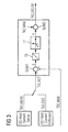
- a control device 1 ( FIG. 1 ) is assigned to an electric machine 3. Furthermore, an operating device 5 is provided for operating the control device and thus the electric machine 3.
- the operating device 5 can in principle be formed separately from the control device 1, but it can form a structural unit with the control device 1.
- the electric machine 3 may be, for example, a synchronous machine. In principle, however, it can also be any other electrical machine.
- a synchronous machine comprises a stator with three winding strands, which are each arranged as a result offset by 120 °.
- the synchronous machine further comprises a rotor, on which permanent magnets are arranged.
- the rotor with the permanent magnets can be rotationally symmetrical - fully charged rotor - or with pronounced poles - Schenkelpol noter - be formed.
- the stator comprises a three-phase symmetrical winding system.
- the operating device 5 and the control device 1 are designed to realize a field-oriented current control.
- the d axis coincides with the orientation of the respective poles of the rotor, while the q axis is perpendicular to the d axis.
- the d-axis is also referred to as the real axis and the q-axis as the imaginary axis.
- the control device 1 is intentionally supplied on the input side with a DC input current I DC and a DC input voltage U DC . For this purpose, it can be electrically connected to an electrical system of a motor vehicle.
- the control device 1 comprises an actuator unit 7.
- the actuator unit 7 preferably comprises an inverter which is designed in particular as a three-phase inverter and which is assigned a space vector pulse width modulator and by means of which then the phase currents for the individual motor strings are generated.
- the inverter is assigned an intermediate circuit, which comprises an intermediate circuit capacitor, which is arranged electrically parallel to the vehicle electrical system voltage supply.
- the operating device 5 comprises an observer, by means of which a DC input current I DC can be determined, specifically an estimated value I DC, EST of the DC input current.
- the observer includes a model ( FIG. 2 ) of the electric machine 3 and the control device 1.
- An ohmic resistance R DC models a DC part of the control device and thus all components through which the DC input current I DC flows.
- An AC part of the control device and the electric machine 3 is modeled by means of respective resistive resistors. Through them, in terms of active power accounting significant losses in Switching elements of the inverter and modeled in the respective lines to the outputs of the control device.
- the switching elements in the inverter in this context include in particular power MOSFET transistors.
- a particularly precise modeling is possible if the ohmic resistance R AC, ECU is determined depending on a temperature, preferably the temperature of the control device. This is preferably done taking into account a non-linear temperature dependence, which models the behavior of power MOSFET transistors particularly well.
- ohmic resistors R AC, MOT are also provided, by means of which the electric machine 3 is modeled in terms of losses occurring in it.
- the ohmic resistance R AC, MOT is plotted for each phase and is also the same for the different phases.
- the ohmic resistor R AC, MOT in particular represents the ohmic resistance in the windings, in particular in copper windings of the electric machine 3.
- the observer also includes a modeling of an internal active power P I, AC based on several parameters, which are described below on the basis of FIG. 4 are explained in more detail.
- the observer includes an active power accounting, which is explained in more detail below.
- Equation F1 indicates a relationship between a DC input active power P DC and the DC input current I DC and the DC input voltage U DC .
- An equation F2 indicates a calculation rule for determining a DC connection loss real power P ESR , which In particular, losses are modeled in the DC link, which are significantly caused by charging and discharging the DC link capacitor.
- the DC link loss real power P ESR can be estimated with sufficient accuracy from a product of a share factor k ESR and the DC input active power P DC .
- the proportion factor k ESR can be determined in particular empirically by appropriate tests with an arrangement of the electric machine 3 and the control device 1.
- Equation F4 specifies a calculation rule for determining a DC loss active power P L, DC depending on the ohmic resistance R DC , which models the DC part of the control device 1, and the DC input current I DC .
- Equation F6 gives a relationship again for determining an AC loss active power P L, AC depending on the ohmic resistance R AC , which models the AC part of the control device, the electric machine 3 and which according to the equation F8 from the sum of the ohmic resistance R AC , ECU and the ohmic resistance R AC, MOT is determined.
- the alternating current I AC corresponds to a square root of a sum of a squared d-motor current I d and a squared q-motor current I q .
- the d-motor current I d and the q-motor current I q may, for example, be derived from measurement signals from corresponding current sensors for detecting the respective motor currents in the individual lines (RST) of the electrical machine, but they may also be estimated values determined by means of a suitable model become.
- F12 is an equation for an internal active power P I, AC , which depends on an electrical angular frequency ⁇ el , which is derived from a rotor speed and a pole pair number of the electric machine, a chained flux ⁇ , a d-motor inductance L d , a q Motor inductance L q and the d and q motor currents I d , I q .
- the electrical angular frequency ⁇ el is preferably derived from a measuring signal of a position sensor, which detects a rotational angle of the rotor relative to a predetermined reference mark on the stator and thus determines the rotational speed of the rotor relative to the stator.
- the concatenated flux ⁇ is preferably determined as a function of a rotor temperature, and preferably with a suitable characteristic curve.
- the rotor temperature is preferably determined as a function of a winding temperature by means of a corresponding model which maps the relationship between the two variables.
- the model is preferably determined by appropriate tests or simulations.
- the d-motor inductance L d and the q-motor inductance L q are preferably determined as a function of current values of the d-motor current I d and the q-motor current I q .
- the equation F12 is particularly applicable to a salient-pole machine, which is also called a hybrid permanent-induction machine (HyPMSM).
- An equation F14 represents a relationship for determining the internal active power P I, AC for a permanent-synchronous machine, which is designed as a full-collector.
- the internal active power P I, AC represents the power converted into mechanical power in the electrical machine.
- Equation F16 represents the relationship between an AC active power P AC and the inner active power P I, AC and the AC loss active power P L, AC .
- Equation F18 then illustrates active power accounting where the DC input active power P DC is equal to a sum of the DC link loss real power P ESR , the DC loss active power P L, DC, and the AC active power P AC .
- the equation F20 is obtained, and the equations F18 and F20 represent the relationship for engine operation of the electric machine 3.
- Equation F22 represents the active power accounting for the regenerative operation of the electric machine. Accordingly, the equation F24 for the regenerative operation after substituting the relations F1 to F16 in F22 and resolving them for the DC input current I DC will then give a calculation instruction for obtaining the DC input current I DC .
- Equation F30 then reflects a relationship applicable to both regenerative and engine operation for determining the DC input current I DC , where a placeholder p is given by the equation F26 and a placeholder s is given by the one equation F28.
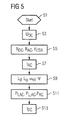
- a start takes place.
- the DC input voltage U DC is determined.
- a corresponding voltage sensor is preferably provided.
- the ohmic resistances R DC and R AC are determined. These may be fixed in a particularly simple embodiment, but they are preferably determined as a function of a temperature.
- the temperature of the control device 1 is determined, which is preferably done by means of a suitable sensor and then determines the ohmic resistance R DC and / or the ohmic resistance R AC, ECU depending on the temperature of the control device 1.
- a temperature of the electric machine 3 is preferably determined, and that is preferably the winding temperature.
- the ohmic resistance R AC, MOT is then determined.
- the resistance R AC is then determined according to the equation F8.
- the share factor k ESR is determined in step S5. This is preferably fixed. However, it can also be dependent on any size and depending on this then be determined.
- a step S7 the d-motor current I d and the q-motor current I q are determined and, as already explained above, either dependent on corresponding measured values of the phase currents in the individual strings (r, s, t) or also by means of a suitable Modeling comprising the park transformation.
- the alternating current I AC is then determined by means of equation F10.
- the d-motor inductance L d and the q-motor inductance L q are determined.
- the d-motor inductance L d and the q-motor inductance L q are preferably determined as a function of the d, q motor currents I d , I q .
- the speed ⁇ el is determined as a function of the measurement signal of the position sensor.
- the concatenated flux ⁇ is preferably determined as a function of a rotor temperature by means of a suitably predetermined characteristic which has been determined in advance by tests or simulations.
- the rotor temperature is preferably determined as a function of the winding temperature by means of a corresponding model, which maps the relationship between the two variables. This too is preferably also determined in advance by corresponding experiments or simulations.
- the internal active power P I, AC is determined as a function of the equation F12 or F14 and the active AC loss power P L, AC is determined by means of the equation F6.
- the AC active power P AC is then determined by the equation F16.
- a step S30 the DC input current I DC is determined by corresponding application of the equation F30. In this way, an estimated value I DC, EST of the DC input current can be easily determined.
- a control difference E is determined from the difference between a predetermined maximum value I DC, MAX of the DC input current and a current DC input current I DC, ACT .
- the current DC input current I DC, ACT is assigned the estimated value I DC, EST of the DC input current, which is determined in step S13, or alternatively, this can also be a measured value I DC, MEAS be assigned to the DC input current, if a corresponding current sensor is provided.
- a controller 15 is provided, to which the control difference E is supplied on the input side, and which is preferably designed as an integral controller.
- the output signal of the regulator 15 is supplied on the input side to a limiter 17, which is designed such that a control signal Y generated on the output side can not assume positive values.
- the maximum value I DC, MAX of the DC input current is predetermined.
- the controller 15 reduces on the output side a DC limit value I AC, DCLIM of the alternating current, which is determined in a further summation Sum2 by summing the control signal Y and a predetermined maximum value I AC, MAX of the alternating current.
- the DC limit value I AC, DCLIM of the alternating current preferably influences a setpoint value for setting the d-motor current I d and / or the q-motor current Iq.
- control signal Y is reduced in the direction 0 because the limiter 17 prevents the control signal Y from assuming values greater than zero.
- a diagnosis can be made by determining the respective estimated value I DC of the DC input current by comparing the respective estimated value I DC, EST and the measured value I DC, MEAS of the DC input current.
- the observer by means of which the estimated value I DC, EST is then determined, can be used to check the plausibility of the measured value I DC, MEAS of the DC input current.
Landscapes
- Engineering & Computer Science (AREA)
- Chemical & Material Sciences (AREA)
- Combustion & Propulsion (AREA)
- Transportation (AREA)
- Mechanical Engineering (AREA)
- Power Engineering (AREA)
- Control Of Ac Motors In General (AREA)
- Control Of Electric Motors In General (AREA)
Claims (10)
- Procédé permettant de faire fonctionner une machine électrique (3), au cours duquel un courant continu d'entrée (IDC) d'un dispositif de commande (1), qui est affecté à la machine électrique (3), est déterminé à l'aide d'un observateur en fonction d'un bilan de puissance effective de la machine électrique (3) et du dispositif de commande (1), qui lui est affecté, et par modélisation de la composante en courant continu du dispositif de commande (1) au moyen d'une résistance ohmique (RDC) et d'une composante en courant alternatif du dispositif de commande (1) et de la machine électrique (3) au moyen de résistances ohmiques respectives (RAC,ECU, RAC,MOT) , caractérisé par le fait que, pour le bilan de puissance effective, la puissance effective continue d'entrée PDC (F1) est égale à la somme de la puissance effective de perte de la liaison en continu PESR (F2), de la puissance effective continue de perte PL,DC (F4) et de la puissance effective en alternatif PAC (F8).
- Procédé selon la revendication 1, caractérisé par le fait que la puissance effective continue d'entrée PDC est un produit de l'intensité du courant continu d'entrée IDC et de la tension continue d'entrée UDC.
- Procédé selon la revendication 1 ou 2, caractérisé par le fait que la puissance effective de perte PESR de la liaison en continu est calculée à l'aide de la formule:

dans laquelle kESR est un facteur proportionnel déterminé d'une façon empirique. - Procédé selon l'une des revendications précédentes, caractérisé par le fait que la puissance effective continue de perte PL.DC est calculée à l'aide de la formule:

- Procédé selon l'une des revendications précédentes, caractérisé par le fait que la puissance effective en alternatif PAC est une somme de la puissance effective interne PI.AC (F12) et de la puissance effective de perte en alternatif PL.AC (F6) .
- Procédé selon l'une des revendications précédentes, caractérisé par le fait que le bilan de la puissance effective comprend une composante de puissance qui comprend une fraction donnée d'une puissance continue effective d'entrée PDC (F1) du dispositif de commande (1).
- Procédé selon l'une des revendications précédentes, caractérisé par le fait que la résistance ohmique (RDC), qui est prévue pour la modélisation de la composante en courant continu du dispositif de commande (1), est déterminée en fonction d'une température.
- Procédé selon l'une des revendications précédentes, caractérisé par le fait que la résistance ohmique respective (RAC,ECU) , qui est prévue pour la modélisation de la composante en courant alternatif du dispositif de commande (1), est déterminée en fonction d'une température du dispositif de commande (1).
- Procédé selon l'une des revendications précédentes, caractérisé par le fait que la résistance ohmique respective (RAC,MOT) , qui est prévue pour la modélisation de la machine électrique (3), est déterminée en fonction de la température de la machine électrique (3).
- Dispositif permettant de faire fonctionner une machine électrique, lequel dispositif est conçu pour déterminer, à l'aide d'un observateur, un courant continu d'entrée (IDC) d'un dispositif de commande (1), qui est affecté à la machine électrique (3), et ceci en fonction d'un bilan de puissance effective de la machine électrique (3) et du dispositif de commande (1), qui lui est affecté, et d'une modélisation de la composante en courant continu du dispositif de commande (1) au moyen d'une résistance ohmique (RDC) et d'une composante en courant alternatif du dispositif de commande (1) et de la machine électrique (3) au moyen de résistances ohmiques respectives (RAC,ECU, RAC.MOT) , caractérisé par le fait que, pour le bilan de puissance effective, la puissance continue effective d'entrée PDC (F1) est égale à la somme de la puissance effective de perte PESR de la liaison en continu (F2), de la puissance effective de perte en continu PL.DC (F4) et de la puissance effective en alternatif PAC (F8) .
Applications Claiming Priority (2)
| Application Number | Priority Date | Filing Date | Title |
|---|---|---|---|
| DE102007007851 | 2007-02-16 | ||
| DE102007017296A DE102007017296A1 (de) | 2007-02-16 | 2007-04-12 | Verfahren und Vorrichtung zum Betreiben einer elektrischen Maschine |
Publications (2)
| Publication Number | Publication Date |
|---|---|
| EP1959552A1 EP1959552A1 (fr) | 2008-08-20 |
| EP1959552B1 true EP1959552B1 (fr) | 2010-03-10 |
Family
ID=39563394
Family Applications (1)
| Application Number | Title | Priority Date | Filing Date |
|---|---|---|---|
| EP20080100841 Ceased EP1959552B1 (fr) | 2007-02-16 | 2008-01-23 | Procédé et dispositif destinés au fonctionnement d'une machine électrique |
Country Status (1)
| Country | Link |
|---|---|
| EP (1) | EP1959552B1 (fr) |
Families Citing this family (2)
| Publication number | Priority date | Publication date | Assignee | Title |
|---|---|---|---|---|
| DE102008041862A1 (de) * | 2008-09-08 | 2010-03-11 | Zf Lenksysteme Gmbh | Verfahren zum Betrieb eines elektronischen Wechselrichters in einer elektrischen Servolenkung |
| US8796982B2 (en) * | 2011-12-15 | 2014-08-05 | Eaton Corporation | System and method for detecting phase loss and diagnosing DC link capacitor health in an adjustable speed drive |
Family Cites Families (4)
| Publication number | Priority date | Publication date | Assignee | Title |
|---|---|---|---|---|
| JPH048192A (ja) * | 1990-04-25 | 1992-01-13 | Hitachi Ltd | 電動機の抵抗値測定方法とその装置および電気車の制御方法とその装置 |
| US5442268A (en) * | 1993-05-13 | 1995-08-15 | Hughes Aircraft Company | Torque oscillation compensation using torque emulator/observer feedback |
| US5998880A (en) * | 1997-08-07 | 1999-12-07 | General Electric Company | AC locomotive operation without DC current sensor |
| JP3892804B2 (ja) * | 2002-12-25 | 2007-03-14 | 株式会社日立製作所 | 電力変換装置とその制御方法 |
-
2008
- 2008-01-23 EP EP20080100841 patent/EP1959552B1/fr not_active Ceased
Also Published As
| Publication number | Publication date |
|---|---|
| EP1959552A1 (fr) | 2008-08-20 |
Similar Documents
| Publication | Publication Date | Title |
|---|---|---|
| EP1985007B1 (fr) | Procede et dispositif de fonctionnement d'une machine synchrone | |
| EP2499737B1 (fr) | Procédé de contrôle de plausibilité du couple d'une machine électrique, et régulateur de machine servant à la régulation d'une machine électrique et à la mise en oeuvre de ce procédé | |
| DE112013005190T5 (de) | Verbesserungen bei elektrischen Servolenksystemen | |
| DE102014016452B4 (de) | Verfahren zum Ermitteln einer Statorwicklungstemperatur einer elektrischen Maschine | |
| EP2666238B1 (fr) | Procédé de détermination de la position du rotor d'une machine électrique | |
| DE102016203273A1 (de) | Verfahren und Anordnung zur Überwachung eines Rotorpositionssensors einer PSM-Maschine | |
| WO1997008820A1 (fr) | Procede et dispositif de correction de la direction de flux d'un modele de flux d'un moteur a champ rotatif, commande sans capteur et par orientation de champ jusqu'a une frequence zero | |
| DE102017007422A1 (de) | Verfahren zum Ermitteln von Fertigungstoleranzen einer elektrischen Maschine | |
| DE102009054546A1 (de) | Ermittlung des Innenwiderstands einer Batteriezelle einer Traktionsbatterie, die mit einem steuerbaren Motor/Generator verbunden ist | |
| DE102013012861A1 (de) | Diagnoseverfahren für eine elektrische Maschine | |
| EP3157165A1 (fr) | Procédé de détermination d'une température d'un rotor | |
| DE112017001330T5 (de) | Motorsteuerungsvorrichtung | |
| DE102016224178A1 (de) | Steuerung einer sechsphasigen PSM | |
| EP1959552A1 (fr) | Procédé et dispositif destinés au fonctionnement d'une machine électrique | |
| EP3348434A1 (fr) | Procédé de surveillance d'un système d'entraînement, en particulier d'un groupe motopropulseur d'un véhicule électrique et dispositif de commande fonctionnant selon ledit procédé | |
| DE102019202464A1 (de) | Verfahren und Steuervorrichtung zum Ermitteln zumindest eines Kennwerts eines Antriebsstrangs, der sich im eingebauten Zustand in einem elektrisch antreibbaren Kraftfahrzeug befindet, sowie Kraftfahrzeug | |
| DE102007017296A1 (de) | Verfahren und Vorrichtung zum Betreiben einer elektrischen Maschine | |
| EP3406027B1 (fr) | Dispositif et procédé de commande d'une machine électrique | |
| EP2360830B1 (fr) | Procédé et dispositif de simulation d'un convertisseur électromécanique | |
| WO2015120851A2 (fr) | Procédé de détermination d'un état thermique d'un moteur électrique dans un entraînement hybride de véhicule automobile | |
| AT522279B1 (de) | Verfahren zum Betreiben einer Antriebsvorrichtung, Computerprogrammprodukt, Antriebsvorrichtung sowie Kraftfahrzeug | |
| DE102015220020B4 (de) | Anordnung und Verfahren zur Erkennung einer elektrischen Leitungsunterbrechung beim Betrieb eines Antriebssystems | |
| EP4070449A1 (fr) | Procédé de fonctionnement d'une machine électrique | |
| DE102017208413A1 (de) | Überwachung eines Drehmoments einer Drehfeldmaschine | |
| DE102012102050A1 (de) | Verfahren zur fortlaufenden Bestimmung von Rotorlagewinkelwerten eines Elektromotors |
Legal Events
| Date | Code | Title | Description |
|---|---|---|---|
| PUAI | Public reference made under article 153(3) epc to a published international application that has entered the european phase |
Free format text: ORIGINAL CODE: 0009012 |
|
| AK | Designated contracting states |
Kind code of ref document: A1 Designated state(s): AT BE BG CH CY CZ DE DK EE ES FI FR GB GR HR HU IE IS IT LI LT LU LV MC MT NL NO PL PT RO SE SI SK TR |
|
| AX | Request for extension of the european patent |
Extension state: AL BA MK RS |
|
| 17P | Request for examination filed |
Effective date: 20090220 |
|
| 17Q | First examination report despatched |
Effective date: 20090318 |
|
| AKX | Designation fees paid |
Designated state(s): DE FR |
|
| GRAP | Despatch of communication of intention to grant a patent |
Free format text: ORIGINAL CODE: EPIDOSNIGR1 |
|
| GRAS | Grant fee paid |
Free format text: ORIGINAL CODE: EPIDOSNIGR3 |
|
| GRAA | (expected) grant |
Free format text: ORIGINAL CODE: 0009210 |
|
| AK | Designated contracting states |
Kind code of ref document: B1 Designated state(s): DE FR |
|
| REF | Corresponds to: |
Ref document number: 502008000423 Country of ref document: DE Date of ref document: 20100422 Kind code of ref document: P |
|
| PLBE | No opposition filed within time limit |
Free format text: ORIGINAL CODE: 0009261 |
|
| STAA | Information on the status of an ep patent application or granted ep patent |
Free format text: STATUS: NO OPPOSITION FILED WITHIN TIME LIMIT |
|
| 26N | No opposition filed |
Effective date: 20101213 |
|
| REG | Reference to a national code |
Ref country code: FR Ref legal event code: PLFP Year of fee payment: 9 |
|
| REG | Reference to a national code |
Ref country code: FR Ref legal event code: PLFP Year of fee payment: 10 |
|
| REG | Reference to a national code |
Ref country code: FR Ref legal event code: PLFP Year of fee payment: 11 |
|
| REG | Reference to a national code |
Ref country code: DE Ref legal event code: R084 Ref document number: 502008000423 Country of ref document: DE |
|
| REG | Reference to a national code |
Ref country code: DE Ref legal event code: R081 Ref document number: 502008000423 Country of ref document: DE Owner name: CONTINENTAL AUTOMOTIVE TECHNOLOGIES GMBH, DE Free format text: FORMER OWNER: CONTINENTAL AUTOMOTIVE GMBH, 30165 HANNOVER, DE |
|
| P01 | Opt-out of the competence of the unified patent court (upc) registered |
Effective date: 20230522 |
|
| REG | Reference to a national code |
Ref country code: DE Ref legal event code: R081 Ref document number: 502008000423 Country of ref document: DE Owner name: CONTINENTAL AUTOMOTIVE TECHNOLOGIES GMBH, DE Free format text: FORMER OWNER: CONTINENTAL AUTOMOTIVE TECHNOLOGIES GMBH, 30165 HANNOVER, DE |
|
| PGFP | Annual fee paid to national office [announced via postgrant information from national office to epo] |
Ref country code: DE Payment date: 20240131 Year of fee payment: 17 |
|
| PGFP | Annual fee paid to national office [announced via postgrant information from national office to epo] |
Ref country code: FR Payment date: 20240124 Year of fee payment: 17 |
|
| REG | Reference to a national code |
Ref country code: DE Ref legal event code: R119 Ref document number: 502008000423 Country of ref document: DE |
|
| PG25 | Lapsed in a contracting state [announced via postgrant information from national office to epo] |
Ref country code: DE Free format text: LAPSE BECAUSE OF NON-PAYMENT OF DUE FEES Effective date: 20250801 |
|
| PG25 | Lapsed in a contracting state [announced via postgrant information from national office to epo] |
Ref country code: FR Free format text: LAPSE BECAUSE OF NON-PAYMENT OF DUE FEES Effective date: 20250131 |