EP1959186A2 - Stativ mit wenigstens drei Stativbeinen - Google Patents
Stativ mit wenigstens drei Stativbeinen Download PDFInfo
- Publication number
- EP1959186A2 EP1959186A2 EP08001873A EP08001873A EP1959186A2 EP 1959186 A2 EP1959186 A2 EP 1959186A2 EP 08001873 A EP08001873 A EP 08001873A EP 08001873 A EP08001873 A EP 08001873A EP 1959186 A2 EP1959186 A2 EP 1959186A2
- Authority
- EP
- European Patent Office
- Prior art keywords
- tripod
- legs
- leg
- stand
- tripod legs
- Prior art date
- Legal status (The legal status is an assumption and is not a legal conclusion. Google has not performed a legal analysis and makes no representation as to the accuracy of the status listed.)
- Granted
Links
- 239000002390 adhesive tape Substances 0.000 claims description 3
- 238000003780 insertion Methods 0.000 claims description 2
- 230000037431 insertion Effects 0.000 claims description 2
- 238000009434 installation Methods 0.000 description 3
- 238000010276 construction Methods 0.000 description 2
- 230000000694 effects Effects 0.000 description 2
- 239000003302 ferromagnetic material Substances 0.000 description 2
- 239000000463 material Substances 0.000 description 2
- 229910052751 metal Inorganic materials 0.000 description 2
- 239000002184 metal Substances 0.000 description 2
- RYGMFSIKBFXOCR-UHFFFAOYSA-N Copper Chemical compound [Cu] RYGMFSIKBFXOCR-UHFFFAOYSA-N 0.000 description 1
- 238000004378 air conditioning Methods 0.000 description 1
- 229910052782 aluminium Inorganic materials 0.000 description 1
- XAGFODPZIPBFFR-UHFFFAOYSA-N aluminium Chemical compound [Al] XAGFODPZIPBFFR-UHFFFAOYSA-N 0.000 description 1
- 238000005452 bending Methods 0.000 description 1
- 229910052802 copper Inorganic materials 0.000 description 1
- 239000010949 copper Substances 0.000 description 1
- 238000006073 displacement reaction Methods 0.000 description 1
- 238000005553 drilling Methods 0.000 description 1
- 238000005516 engineering process Methods 0.000 description 1
- 238000010438 heat treatment Methods 0.000 description 1
- 238000002347 injection Methods 0.000 description 1
- 239000007924 injection Substances 0.000 description 1
- 238000004519 manufacturing process Methods 0.000 description 1
- 238000000034 method Methods 0.000 description 1
- 239000002689 soil Substances 0.000 description 1
- 239000007787 solid Substances 0.000 description 1
- 229910001220 stainless steel Inorganic materials 0.000 description 1
- 239000010935 stainless steel Substances 0.000 description 1
- 238000009423 ventilation Methods 0.000 description 1
Images

Classifications
-
- F—MECHANICAL ENGINEERING; LIGHTING; HEATING; WEAPONS; BLASTING
- F16—ENGINEERING ELEMENTS AND UNITS; GENERAL MEASURES FOR PRODUCING AND MAINTAINING EFFECTIVE FUNCTIONING OF MACHINES OR INSTALLATIONS; THERMAL INSULATION IN GENERAL
- F16M—FRAMES, CASINGS OR BEDS OF ENGINES, MACHINES OR APPARATUS, NOT SPECIFIC TO ENGINES, MACHINES OR APPARATUS PROVIDED FOR ELSEWHERE; STANDS; SUPPORTS
- F16M11/00—Stands or trestles as supports for apparatus or articles placed thereon ; Stands for scientific apparatus such as gravitational force meters
- F16M11/02—Heads
- F16M11/16—Details concerning attachment of head-supporting legs, with or without actuation of locking members thereof
-
- F—MECHANICAL ENGINEERING; LIGHTING; HEATING; WEAPONS; BLASTING
- F16—ENGINEERING ELEMENTS AND UNITS; GENERAL MEASURES FOR PRODUCING AND MAINTAINING EFFECTIVE FUNCTIONING OF MACHINES OR INSTALLATIONS; THERMAL INSULATION IN GENERAL
- F16M—FRAMES, CASINGS OR BEDS OF ENGINES, MACHINES OR APPARATUS, NOT SPECIFIC TO ENGINES, MACHINES OR APPARATUS PROVIDED FOR ELSEWHERE; STANDS; SUPPORTS
- F16M11/00—Stands or trestles as supports for apparatus or articles placed thereon ; Stands for scientific apparatus such as gravitational force meters
- F16M11/20—Undercarriages with or without wheels
- F16M11/22—Undercarriages with or without wheels with approximately constant height, e.g. with constant length of column or of legs
-
- F—MECHANICAL ENGINEERING; LIGHTING; HEATING; WEAPONS; BLASTING
- F16—ENGINEERING ELEMENTS AND UNITS; GENERAL MEASURES FOR PRODUCING AND MAINTAINING EFFECTIVE FUNCTIONING OF MACHINES OR INSTALLATIONS; THERMAL INSULATION IN GENERAL
- F16M—FRAMES, CASINGS OR BEDS OF ENGINES, MACHINES OR APPARATUS, NOT SPECIFIC TO ENGINES, MACHINES OR APPARATUS PROVIDED FOR ELSEWHERE; STANDS; SUPPORTS
- F16M11/00—Stands or trestles as supports for apparatus or articles placed thereon ; Stands for scientific apparatus such as gravitational force meters
- F16M11/20—Undercarriages with or without wheels
- F16M11/24—Undercarriages with or without wheels changeable in height or length of legs, also for transport only, e.g. by means of tubes screwed into each other
- F16M11/242—Undercarriages with or without wheels changeable in height or length of legs, also for transport only, e.g. by means of tubes screwed into each other by spreading of the legs
-
- F—MECHANICAL ENGINEERING; LIGHTING; HEATING; WEAPONS; BLASTING
- F16—ENGINEERING ELEMENTS AND UNITS; GENERAL MEASURES FOR PRODUCING AND MAINTAINING EFFECTIVE FUNCTIONING OF MACHINES OR INSTALLATIONS; THERMAL INSULATION IN GENERAL
- F16M—FRAMES, CASINGS OR BEDS OF ENGINES, MACHINES OR APPARATUS, NOT SPECIFIC TO ENGINES, MACHINES OR APPARATUS PROVIDED FOR ELSEWHERE; STANDS; SUPPORTS
- F16M2200/00—Details of stands or supports
- F16M2200/08—Foot or support base
Definitions
- the invention relates to a tripod with at least three tripod legs, which is used for holding a leveling, Lotungs and Winkelkalibri füribri füribri füribri füribri füribri fürinsky as a tripod with at least three tripod legs, which is used for holding a leveling, Lotungs and Winkelkalibri füribri fürinsky as a tripod with at least three tripod legs, which is used for holding a leveling, Lotungs and Winkelkalibri mecanices, e.g. a line laser, NOTElaser- or small rotary laser device, is executed, wherein the tripod legs are designed with their mutually facing ends rotatable about a common axis and each of the tripod legs with a distance from the axis by the same angle is bent in each case.
- a leveling, Lotungs and Winkelkalibri füribri fürinsinstrumentes e.g. a line laser, NOTElaser- or small rotary laser device
- the line lasers are e.g. equipped with a photo thread. This allows the user to use very small or normal sized photo tripods, which usually have a crank column adjustable central column (height fine adjustment of the line laser).
- Another approach is telescopic columns that are clamped vertically between floor and ceiling. This can be set in a room any altitude for the placement of a line laser.
- fixing aids for connection to pipes, for attachment with magnets or by direct screwing to a wall.
- block-like fastening aids are known, which can be transformed by hinged about horizontal axes foot elements in a three-legged tripod.
- brackets for leveling, Lotungswinkel and Winkelkalibri für sinstrumente are also from the WO2006 / 02289 of the EP1108981A2 , of the US 5541727A and the US5584458A known. In all embodiments, but it requires some pre-assembly and the construction parts are large and expensive.
- the DE 20 202 354 119 shows a tripod of the type mentioned with three tripod legs rotatable about a common axis.
- the tripod legs are turned apart in the generic state of the art so that a tripod is created so that the tripod stands securely on the ground on his tripod legs and so the instruments placed on the tripod is held securely.
- the invention has now set itself the task of developing a generic tripod to the effect that it also serves as a wall mount for a leveling, Lotungs and Winkelkalibri mecanic can be used.
- the lowermost stand leg has, on a freely cantilevered portion, a cross-section which projects freely and preferably further, threaded studs.
- the threaded bolt on the cantilevered portion of the bottommost tripod leg can thus be suitable or provided for holding the leveling, Lotungs and Winkelkalibri réellesinstrumentes.
- the tripod as usual in the prior art, has a threaded bolt arranged on the common axis of the tripod legs for holding the leveling, Lotungs and Winkelkalibri réellesinstrumentes, it is in the threaded bolt according to the invention at the cantilevered portion of the bottom of the tripod leg to another , or additional threaded bolt.
- each of the tripod legs is bent at the same angle at a turn, each tripod leg having a portion disposed between the common axis and the turn and the cantilevered portion on the opposite side of the turn for that portion.
- a tripod Due to the possibility of twisting the tripod legs is achieved that a tripod can be practically merged into the size of three tripod legs formed from flat parts and that the tripod can be set up ready by simply moving apart with each other by about 120 ° staggered positions. Especially for a universally applicable small tripod this is an optimal design. Therefore, such a tripod could also be readily manufactured from plastic injection molded parts. The tripod can also be set up stable on rough and uneven surfaces.
- the tripod legs have side boundaries, which converge towards each other at least near the cantilevered support ends of the tripod legs. Therefore, these ends are formed into a point or at least a rounded tip.
- the topmost tripod leg in the common axis of the tripod legs is projecting a threaded bolt, which is provided with an actuating disk arranged below the bottommost tripod leg is in active connection. It can therefore be a fixture of the instruments or equipment in the same manner as in a photographic equipment.
- the tripod legs are arranged at least in the region of the common axis with a small distance from each other. In this way it has become possible to manufacture the tripod legs from a flat profile, because a mutual pivoting about the common axis has been made possible by this distance in a simple manner.
- tripod legs are arranged in the swung together state over their entire length with a small distance from each other. In a pivoting, so when swinging the tripod legs in the support position and also in the pivoted position, the tripod legs are never in the way.
- an advantageous construction is that the two sections of the uppermost tripod leg formed by the bend are the longest and these sections of the lowermost tripod leg are designed to be the shortest.
- the tripod legs do not interfere with each other in a pivoting process and also always an exactly aligned installation on the ground is possible.
- a particular embodiment provides that the two sections of the tripod legs form an angle of 135 ° to each other.
- This special choice of angle is particularly convenient to use the tripod for wall mounting and mounting an instrument or device. It is then a tripod leg relative to the other tripod legs swung 180 ° of the common axis and used to attach the tripod to a wall or an approximately vertically oriented holder. The other 180 ° pivoted to tripod legs are then aligned so that the cantilevered sections of the tripod legs form an angle of 90 ° with each other. The instrument or device can then be set up practically oriented again in the appropriate position.
- the lowermost tripod leg on the cantilevered portion has a freely projecting, preferably further, threaded bolts transversely thereto. It can therefore or the like when using the stand on a wall. in the same way the instrument or device are fixed.
- the tripod can be used advantageously even when used on a wall or other holder, it is provided that at least one of the tripod legs, preferably the uppermost tripod leg in the cantilevered portion recesses, slots, holes or the like. having. It can be done by any fastening means in a simple manner, a hooking or attachment.
- a further embodiment provides that at least one of the tripod legs, preferably the uppermost tripod leg on the cantilevered portion at least one preferably sunk arranged in the surface of the tripod leg arranged permanent magnet.
- At least one of the tripod legs preferably the uppermost tripod leg in the cantilevered portion has keyhole-like recesses.
- the tripod or the corresponding tripod leg can be hung after mounting a screw on a wall.
- the tripod e.g. to be attached to a tubular holder.
- an adapter for insertion between a tubular holder and a tripod leg wherein the adapter has a groove-like recess for positionally secure application to the tubular holder.
- the adapter by means of a fastening strap or a tension band on a tubular holder can be fixed. It is thereby create a secure mechanical connection.
- Another way of holding a tripod according to the invention on a wall or the like. is given when provided for connecting a tripod leg to a flat wall by means of a double-sided adhesive tape. It is therefore possible for any application of a tripod invention optimal and secure mounting or installation.
- tripod legs 2, 3 and 4 are provided.
- This stand 1 is for holding a leveling, Lotungs and Winkelkalibri füribri füribri füribri füribri füribri für sinstrumentes 5, e.g. a line laser, point laser or small rotation laser device executed.
- this tripod can also be used for other purposes, e.g. for holding photo accessories, if a small tripod is sufficient.
- tripod legs are designed with their ends facing each other about a common axis 6 rotatable. Furthermore, all tripod legs 2, 3, 4 are bent at a distance from the axis 6 by the same angle ⁇ .
- the tripod legs 2, 3, 4 have side boundaries 7, 8, which converge towards each other at least near the cantilevered support ends 9 of the tripod legs 2, 3, 4. It is therefore given just when setting up on the ground a sufficient stability.
- the instrument has a wobble-free surface on bare soil. For example, tilers can thus directly specify the horizontal starting line for laying the wall panels and lay the first row of panels on the laser line. Providing a stable installation on uneven and rough surfaces is the main application of the mini-tripod.
- a threaded bolt 10 is formed projecting the uppermost tripod leg 2 in the common axis 6 of the tripod legs 2, 3, 4, which is operatively connected to an actuating disk 11 arranged below the lowermost stand leg 4 stands. It is such a screw fastening possible and thus a direct solid attack in a threaded hole at the bottom of the instrument. 5
- the tripod legs 2, 3, 4 are arranged at least in the region of the common axis 6 at a small distance A from each other. It is advantageous for structural reasons, when the tripod legs in the swung together state (see in particular Figure 3 ) are arranged over their entire length at a small distance A from each other. As a result, the tripod legs 2, 3, 4 can be made in a simple manner from a flat material, and yet they can be pivoted about the common axis 6 without mutual interference. Without this distance, such a tripod would not swing out or the tripod legs 2, 3, 4 would have to be performed according to the radius of curvature.
- the two resulting from the bend 12 sections 13, 14 of the tripod legs 2, 3, 4 are executed in all tripod legs 2, 3, 4 of different lengths. So are the tripod leg 2, the section 13 is designed with a length B and the section 14 with a length C. In the case of the tripod legs 3 and 4, the sections 13 and 14 are made progressively shorter. The two resulting from the bend 12 sections 13 and 14 of the uppermost tripod leg 2 are thus the longest and these sections 13 and 14 of the bottom tripod leg 13 and 14 executed the shortest.
- a transversely cantilevered further threaded bolt 15 is provided over an actuating disk 16 is rotated and thus can be screwed by operating the same in a threaded bore on the underside of the instrument 5.
- the stand 1 can be fixed in a simple manner to a wall or a corresponding holder.
- at least one of the tripod legs preferably the uppermost tripod leg 2 in the cantilevered portion 14 recesses 17, slots 18, holes or the like. on.
- at least one of the tripod legs, preferably the uppermost tripod leg has keyhole-like recesses in the cantilevered portion. Then, for the time being, two screws provided with heads can be screwed into a wall, whereupon the stand can then be inserted in the area of the keyhole-like recesses 19 of this one tripod leg 2 and held in place by vertical displacement.
- At least one of the tripod legs 2, 3, 4, preferably the uppermost tripod leg 2 at the cantilevered portion 14 carries at least one preferably 20 sunk in the surface of the tripod leg arranged permanent magnet.
- a good support of the tripod 1 to metal furniture or a metallic wall of ferromagnetic material is possible without attaching further fasteners.
- an attachment to an adapter 22 is conceivable, where, for example, at least the regions 21 are made of ferromagnetic material.
- the tripod 1 or at least one tripod leg 2 can also be used, for example, on a tubular holder 23.
- This adapter 23 is provided on its rear side with a groove-like recess 24, thereby enabling a positionally secure application to the tubular holder 23.
- Block-type adapters 26 (according to FIG Figure 9 ) have a marginal V-notch 27 on their underside.
- a transversely through the block going slot 28 is arranged, through which a fastening tape is looped. This type of attachment is suitable for tubular holder 23 with small to smallest diameters.
- the adapter 22 can be fixed by means of a fastening band or a tension band 25 to a tubular holder 23.
- an adapter 22 has been created, which allows attachment to very small tubes up to tubes with a large diameter: this has on the one hand an angular range or the groove-like recess 24, which is big enough to give a credible centering effect.
- the adapter 22 is supplemented with a producible by simple bending fastening tab 29 for the tripod.
- the adapter 22 has a recess 30 for attachment by means of the tension band 25.
- This simple measure has the same purpose as the slot 28 in the block-like adapters 26.
- the attachment of the adapter 22 is easier and without any run through.
- a double-sided adhesive tape is also conceivable, which adheres to the back of the corresponding tripod leg 2 and on the other hand to a wall surface, e.g. is also pressed in the area of tiles. This achieves high holding power and independence from the material. This is particularly advantageous for heating, ventilation and air conditioning technology, where plastic, aluminum, copper and especially stainless steel is used.
Landscapes
- Engineering & Computer Science (AREA)
- General Engineering & Computer Science (AREA)
- Mechanical Engineering (AREA)
- Accessories Of Cameras (AREA)
- Casings For Electric Apparatus (AREA)
- Orthopedics, Nursing, And Contraception (AREA)
- Aiming, Guidance, Guns With A Light Source, Armor, Camouflage, And Targets (AREA)
- Clamps And Clips (AREA)
Abstract
Description
- Die Erfindung betrifft ein Stativ mit wenigstens drei Stativbeinen, welches zur Halterung eines Nivellierungs-, Lotungs- und Winkelkalibrierungsinstrumentes, z.B. eines Linienlaser-, Punktlaser- oder Kleinrotationslasergerätes, ausgeführt ist, wobei die Stativbeine mit ihren einander zugewendeten Enden um eine gemeinsame Achse verdrehbar ausgeführt sind und jedes der Stativbeine mit Abstand von der Achse um jeweils den gleichen Winkel abgebogen ist.
- Für Linienlaser wird eine Reihe von Zubehör angeboten. Es geht immer darum, den Linienlaser relativ zur gewünschten Arbeitsposition aufzustellen. Die Linienlaser sind z.B. mit einem Photogewinde ausgestattet. Damit kann der Anwender sehr kleine oder normalgrosse Photostative einsetzen, die meist eine über Kurbel verstellbare Zentralsäule (Höhenfeinverstellung des Linienlasers) aufweisen. Ein anderer Ansatz sind Teleskopsäulen, die senkrecht zwischen Boden und Decke verspannt werden. Damit kann in einem Raum jede beliebige Höhenlage für die Platzierung eines Linienlasers eingestellt werden.
- Für Punkt - und Linienlaser sind auch Befestigungshilfen bekannt zum Anbinden an Rohre, zur Befestigung mit Magneten oder durch direkte Verschraubung an einer Wand. Es sind auch derartige blockartige Befestigungshilfen bekannt, die durch um horizontale Achsen ausklappbare Fusselemente in ein dreibeiniges Stativ verwandelt werden können.
- Weitere Halterungen für Nivellierungs-, Lotungs- und Winkelkalibrierungsinstrumente sind auch aus der
WO2006/02289 EP1108981A2 , derUS-5541727A und derUS5584458A bekannt. Bei allen Ausgestaltungen bedarf es aber einiger Vormontagearbeiten und die Konstruktionsteile sind groß und aufwändig. - Die
DE 20 202 354 119 zeigt ein Stativ der eingangs genannten Art mit drei um eine gemeinsame Achse verdrehbaren Stativbeinen. Die Stativbeine werden beim gattungsgemäßen Stand der Technik so auseinander gedreht, dass ein Dreibein entsteht, sodass das Stativ auf dem Untergrund auf seinen Stativbeinen sicher steht und so das auf das Stativ aufsetzbare Instrumente sicher gehalten ist. - Die Erfindung hat sich nun zur Aufgabe gestellt, ein gattungsgemäßes Stativ dahingehend weiterzubilden, dass es auch als Wandhalterung für ein Nivellierungs-, Lotungs- und Winkelkalibrierungsinstrument verwendet werden kann.
- Erfindungsgemäß gelingt dies dadurch, dass das unterste Stativbein an einem frei auskragenden Abschnitt einen quer dazu frei auskragenden, vorzugsweise weiteren, Gewindebolzen aufweist.
- Der Gewindebolzen am frei auskragenden Abschnitt des untersten Stativbeins kann somit zur Halterung des Nivellierungs-, Lotungs- und Winkelkalibrierungsinstrumentes geeignet bzw. vorgesehen sein. Wenn das Stativ, wie beim Stand der Technik üblich, einen an der gemeinsamen Achse der Stativbeine angeordneten Gewindebolzen zur Halterung des Nivellierungs-, Lotungs- und Winkelkalibrierungsinstrumentes aufweist, so handelt es sich bei dem erfindungsgemäßen Gewindebolzen am frei auskragenden Abschnitt des untersten Stativbeins um einen weiteren, bzw. zusätzlichen Gewindebolzen. Bevorzugt ist jedes der Stativbeine um jeweils den gleichen Winkel an einer Abbiegung abgebogen ist, wobei jedes Stativbein einen zwischen der gemeinsamen Achse und der Abbiegung angeordneten Abschnitt und auf der zu diesem Abschnitt gegenüberliegenden Seite der Abbiegung den frei auskragenden Abschnitt aufweist.
- Durch die Möglichkeit des Verdrehens der Stativbeine wird erreicht, dass ein Stativ praktisch auf die Größe von drei aus Flachteilen gebildeten Stativbeinen zusammengelegt werden kann und dass das Stativ durch einfaches Auseinanderschwenken mit um jeweils ca. 120° zueinander versetzte Stellungen einsatzbereit aufgestellt werden kann. Gerade für ein universell einsetzbares kleines Stativ ist dies eine optimale Ausgestaltung. Daher könnte ein solches Stativ auch ohne weiteres aus Kunststoffspritzgussteilen gefertigt werden. Das Stativ kann auch auf rauen und unebenen Oberflächen standsicher aufgestellt werden.
- Damit die Standfestigkeit des Stativs auf dem Boden verbessert wird, wird vorgeschlagen, dass die Stativbeine Seitenbegrenzungen aufweisen, welche zumindest nahe der frei auskragenden Auflageenden der Stativbeine zueinander konvergieren. Es sind daher diese Enden zu einer Spitze oder zumindest zu einer abgerundeten Spitze hin ausgeformt.
- Damit an diesem Stativ, wenn das Stativ auf seinen Stativbeinen steht, die Instrumente oder Geräte ordnungsgemäß befestigt werden können, ist vorgesehen, dass das oberste Stativbein in der gemeinsamen Achse der Stativbeine überragend ein Gewindebolzen ausgebildet ist, welcher mit einer unterhalb des untersten Stativbeines angeordneten Betätigungsscheibe in Wirkverbindung steht. Es kann daher eine Befestigung der Instrumente oder Geräte in gleicher Weise wie bei einer Fotoausrüstung erfolgen.
- Ferner wird vorgeschlagen, dass die Stativbeine zumindest im Bereich der gemeinsamen Achse mit geringem Abstand zueinander angeordnet sind. Auf diese Weise ist es möglich geworden, die Stativbeine aus einem Flachprofil zu fertigen, denn ein gegenseitiges Verschwenken um die gemeinsame Achse ist durch diesen Abstand in einfacher Weise ermöglicht worden.
- In diesem Zusammengang ist noch vorteilhaft, wenn die Stativbeine in zusammengeschwenkten Zustand über deren ganze Länge mit geringem Abstand zueinander angeordnet sind. Bei einem Verschwenkvorgang, also beim Ausschwenken der Stativbeine in die Abstützstellung und auch in der zusammengeschwenkten Stellung sind sich die Stativbeine nie im Wege.
- Damit ein Ausgleich der in verschiedenen Höhenlagen an der gemeinsamen Achse angreifenden Stativbeine geschaffen wird und die gemeinsame Achse bei einem Einsatz des Stativ auf einem Boden praktisch von vorne herein in vertikaler Richtung verläuft, ist vorgesehen, dass die beiden durch die Abbiegung entstandenen Abschnitte der Stativbeine bei allen Stativbeinen unterschiedlich lang ausgeführt sind.
- Dabei liegt eine vorteilhafte Konstruktion darin, dass die beiden durch die Abbiegung entstandenen Abschnitte des obersten Stativbeines am längsten und diese Abschnitte des untersten Stativbeines am kürzesten ausgeführt sind. Dadurch stören sich die Stativbeine nicht gegenseitig bei einem Verschwenkvorgang und außerdem ist immer eine exakt ausgerichtete Aufstellung am Boden möglich.
- Eine besondere Ausgestaltung sieht vor, dass die beiden Abschnitte der Stativbeine einen Winkel von 135° zueinander einschließen. Diese spezielle Wahl des Winkels ist besonders günstig, um das Stativ für die Wandbefestigung und Halterung eines Instrumentes oder Gerätes einzusetzen. Es ist dann ein Stativbein gegenüber den anderen Stativbeinen um 180° der gemeinsamen Achse ausgeschwenkt und dient zur Befestigung des Stativs an einer Wand oder einer annähernd vertikal ausgerichteten Halterung. Die weiteren um 180° dazu verschwenkten Stativbeine sind dann so ausgerichtet, dass die frei auskragenden Abschnitte der Stativbeine einen Winkel von 90° miteinander einschließen. Das Instrument oder Gerät kann dann praktisch wieder in entsprechender Lage ausgerichtet aufgestellt werden.
- In diesem Zusammenhang ist, wie eingangs erwähnt vorgesehen, dass das unterste Stativbein an dem frei auskragenden Abschnitt einen quer dazu frei auskragenden, vorzugsweise weiteren, Gewindebolzen aufweist. Es kann daher bei einem Einsatz des Stativs an einer Wand od.dgl. in gleicher Weise das Instrument oder Gerät fixiert werden.
- Damit das Stativ auch bei einem Einsatz an einer Wand oder einer sonstigen Halterung vorteilhaft eingesetzt werden kann, ist vorgesehen, dass wenigstens eines der Stativbeine, vorzugsweise das oberste Stativbein in dem frei auskragenden Abschnitt Ausnehmungen, Schlitze, Bohrungen od.dgl. aufweist. Es kann dadurch in einfacher Weise ein Einhängen oder eine Befestigung durch irgendwelche Befestigungsmittel erfolgen.
- Eine weitere Ausgestaltung sieht vor, dass wenigstens eines der Stativbeine, vorzugsweise das oberste Stativbein an dem frei auskragenden Abschnitt wenigstens einen vorzugsweise in der Oberfläche des Stativbeines versenkt angeordneten Dauermagneten trägt. Mit einer solchen Ausgestaltung ist es auch denkbar, eine Befestigung des Stativs an einer Wand oder einem Träger aus Metall ohne zusätzliche Befestigungsmittel zu bewerkstelligen.
- Gerade bei einer Wandbefestigung mittels Schrauben mit Kopf ist es vorteilhaft, wenn wenigstens eines der Stativbeine, vorzugsweise das oberste Stativbein in dem frei auskragenden Abschnitt schlüssellochartige Ausnehmungen aufweist. Das Stativ bzw. das entsprechende Stativbein kann nach der Montage einer Schraube an einer Wand eingehängt werden.
- Im Rahmen der Erfindung ist es auch möglich, zusätzliche Maßnahmen vorzusehen, um das Stativ z.B. an einem rohrförmigen Halter zu befestigen. Eine Möglichkeit wird durch die Anordnung eines Adapters zum Einsetzen zwischen einem rohrförmigen Halter und eine Stativbeines gesehen, wobei der Adapter nutartige Ausnehmung aufweist zum lagesicheren Anlegen an den rohrförmigen Halter. Somit kann eine solcher Adapter Fest und ohne Verschwenkmöglichkeit an einem rohrförmigen Halter angebracht werden. Dadurch ist dann auch eine optimal ausgerichtet Halterung für das Stativ ermöglicht worden.
- In diesem Zusammenhang ist es denkbar, dass der Adapter mittels eines Befestigungsbandes oder eines Spannbandes an einem rohrförmigen Halter festlegbar ist. Es ist dadurch eine sichere mechanische Verbindung zu schaffen.
- Eine weitere Möglichkeit der Halterung eines erfindungsgemäßen Stativs am einer Wand od.dgl. ist dann gegeben, wenn zur Verbindung eines Stativbeines an einer ebenen Wand mittels ein Doppelklebeband vorgesehen ist. Es ist also für jede Anwendung eines erfindungsgemäßen Stativs eine optimale und sichere Halterung oder Aufstellung möglich.
- Weitere erfindungsgemäße Merkmale und besondere Vorteile werden in der nachstehenden Beschreibung anhand der Zeichnungen noch näher erläutert. Es zeigen:
- Fig. 1
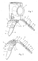
- eine Schrägsicht eines erfindungsgemäßen Stativs mit aufgesetztem Instrument;
- Fig. 2
- eine Schrägsicht des erfindungsgemäßen Stativs ohne aufgesetztes Instrument;
- Fig. 3
- eine Seitenansicht mit in die Ruhelage eingeschwenkten Stativbeinen;
- Fig. 4
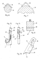
- eine Seitenansicht der Stativbeine in der Ausrichtung für eine Wandbefestigung des Stativs;
- Fig. 5
- die gleiche Darstellung wie in
Fig.4 , jedoch in einer Schrägsicht; - Fig.6
- eine Ansicht der Ausführung nach den
Fig. 4 und 5 in Pfeilrichtung VI inFig.4 von hinten gesehen; - die Fig. 7 - Fig. 9
- einen Adapter zur Anlage an einem rohrförmigen Halter;
- Fig. 10
- eine Schrägsicht eines Adapters;
- Fig. 11
- eine Befestigungsmöglichkeit eines Adapters an einem rohrförmigen Halter;
- Fig. 12
- eine gleiche Darstellung wie in
Fig.11 , jedoch mit angesetztem Stativ und aufgesetztem Instrument. - Bei dem erfindungsgemäßen Stativ 1 sind wenigstens drei Stativbeine 2, 3 und 4 vorgesehen. Dieses Stativ 1 ist zur Halterung eines Nivellierungs-, Lotungs- und Winkelkalibrierungsinstrumentes 5, z.B. eines Linienlaser-, Punktlaser- oder Kleinrotationslasergerätes, ausgeführt. Im Rahmen der Erfindung kann dieses Stativ natürlich auch für andere Zwecke eingesetzt werden, z.B. zur Halterung von Fotozubehör, wenn ein Kleinstativ ausreichend ist.
- Die wesentlichen Merkmale der Erfindung liegen nun darin, dass die Stativbeine mit ihren einander zugewendeten Enden um eine gemeinsame Achse 6 verdrehbar ausgeführt sind. Ferner sind alle Stativbeine 2, 3, 4 mit Abstand von der Achse 6 um jeweils den gleichen Winkel α abgebogen.
- Die Stativbeine 2, 3, 4 weisen Seitenbegrenzungen 7, 8 auf, welche zumindest nahe der frei auskragenden Auflageenden 9 der Stativbeine 2, 3, 4 zueinander konvergieren. Es ist daher gerade beim Aufstellen am Boden eine ausreichende Standsicherheit gegeben. Sind die Stativbeine 2, 3, 4 wie in
Fig.1 und Fig.2 abgebildet ausgedreht, hat das Instrument eine wackelfreie Unterlage auf Rohböden. Beispielsweise Fliesenleger können damit die horizontale Ausgangslinie für das Verlegen der Wandplatten unmittelbar vorgeben und die erste Plattenreihe auf die Laserlinie verlegen. Eine standsichere Aufstellung auf unebenen und rauen Oberflächen zu geben ist die Hauptanwendung des Kleinstativs. - Damit ein Instrument 5 sicher auf dem Stativ 1 gehalten werden kann, ist ein das oberste Stativbein 2 in der gemeinsamen Achse 6 der Stativbeine 2, 3, 4 überragend ein Gewindebolzen 10 ausgebildet, welcher mit einer unterhalb des untersten Stativbeines 4 angeordneten Betätigungsscheibe 11 in Wirkverbindung steht. Es ist so eine Schraubbefestigung möglich und somit ein direkter fester Angriff in einer Gewindebohrung am Boden des Instrumentes 5.
- Die Stativbeine 2, 3, 4 sind zumindest im Bereich der gemeinsamen Achse 6 mit geringem Abstand A zueinander angeordnet. Dabei ist es aus konstruktionstechnischen Gründen vorteilhaft, wenn die Stativbeine in zusammengeschwenkten Zustand (siehe insbesondere
Fig.3 ) über deren ganze Länge mit geringem Abstand A zueinander angeordnet sind. Dadurch können die Stativbeine 2, 3, 4 ein einfacher Weise aus einem Flachmaterial gefertigt werden und trotzdem können diese um die gemeinsame Achse 6 ohne gegenseitige Behinderung verschwenkt werden. Ohne diesen Abstand wäre ein derartiges Stativ nicht ausschwenkbar oder die Stativbeine 2, 3, 4 müssten dem Drehradius entsprechend gewölbt ausgeführt sein. - Die beiden durch die Abbiegung 12 entstandenen Abschnitte 13, 14 der Stativbeine 2, 3, 4 sind bei allen Stativbeinen 2, 3, 4 unterschiedlich lang ausgeführt sind. So sind beim Stativbein 2 der Abschnitt 13 mit einer Länge B ausgeführt und der Abschnitt 14 mit einer Länge C. Bei den Stativbeinen 3 und 4 sind die Abschnitte 13 und 14 zunehmend kürzer ausgeführt. Die beiden durch die Abbiegung 12 entstandenen Abschnitte 13 und 14 des obersten Stativbeines 2 sind also am längsten und diese Abschnitte 13 und 14 des untersten Stativbeines 13 und 14 am kürzesten ausgeführt.
- Grundsätzlich könnten die verschenkbaren Stativbeine 2, 3, 4 zur gemeinsamen Achse 6 hin in einem nahezu beliebigen Winkel α gebogen sein. Es würde sich nur die Aufstandsfläche entsprechend ändern (kleine Fläche = Kippgefahr; grosse Fläche = hohe Standsicherheit). Da das erfindungsgemäße Stativ auch im Wandbereich oder an vertikal verlaufenden Haltern einsetzbar sein soll, ist es sinnvoll, wenn die beiden Abschnitte 13, 14 der Stativbeine 2, 3, 4 einen Winkel α von 135° zueinander einschließen. Dadurch schließen bei einer Wandhalterung die beiden Abschnitte 14 der um 180° zueinander verschwenkten Stativbeine 2 bzw. 3, 4 einen Winkel β von 90° miteinander ein.
- Damit auch bei einem Einsatz des Stativs 1 am Wänden oder vertikal verlaufenden Haltern einsetzbar ist und auch eine entsprechende Befestigung eines Instrumentes 5 erfolgen kann, ist am untersten Stativbein 4 an dem frei auskragenden Abschnitt 14 ein quer dazu frei auskragender weiterer Gewindebolzen 15 vorgesehen, der über eine Betätigungsscheibe 16 verdreht und somit durch Betätigung derselben in eine Gewindebohrung an der Unterseite des Instrumentes 5 eingedreht werden kann.
- Es ist im gezeigten Ausführungsbeispiel auch dafür gesorgt, dass das Stativ 1 in einfacher Art und Weise an einer Wand oder einem entsprechenden Halter befestigt werden kann. Dazu weist wenigstens eines der Stativbeine, vorzugsweise das oberste Stativbein 2 in dem frei auskragenden Abschnitt 14 Ausnehmungen 17, Schlitze, Bohrungen 18 od.dgl. auf. Dabei kann vorgesehen werden, dass wenigstens eines der Stativbeine, vorzugsweise das oberste Stativbein in dem frei auskragenden Abschnitt schlüssellochartige Ausnehmungen aufweist. Dann können vorerst zwei mit Köpfen versehene Schrauben in eine Wand eingedreht werden, worauf dann das Stativ im Bereich der schlüssellochartigen Ausnehmungen 19 dieses einen Stativbeines 2 eingeführt und durch vertikales Verschieben festgehalten werden kann.
- Im Rahmen der Erfindung ist es auch möglich, dass wenigstens eines der Stativbeine 2, 3, 4, vorzugsweise das oberste Stativbein 2 an dem frei auskragenden Abschnitt 14 wenigstens einen vorzugsweise in der Oberfläche des Stativbeines versenkt angeordneten Dauermagneten 20 trägt. Damit ist auch ohne Anbringen weiterer Befestigungsmittel eine gute Halterung des Stativs 1 an Metallmöbeln oder einer metallischen Wand aus ferromagnetischem Material möglich. Auch ist damit eine Befestigung an einem Adapter 22 denkbar, wo beispielsweise zumindest die Bereiche 21 aus ferromagnetischem Material gefertigt sind.
- Mit einem Adapter 22 kann das Stativ 1 oder zumindest ein Stativbein 2 auch beispielsweise an einem rohrförmigen Halter 23 zum Einsatz kommen. Dieser Adapter 23 ist auf seiner Rückseite mit einer nutartige Ausnehmung 24 versehen, um dadurch ein lagesicheres Anlegen an den rohrförmigen Halter 23 zu ermöglichen. Blockartige Adapter 26 (gemäß
Fig.9 ) weisen auf ihrer Unterseite eine marginale V-Kerbe 27 auf. Darüber ist ein quer durch den Block gehendes Langloch 28 angeordnet, durch welches ein Befestigungsband geschlauft wird. Diese Art der Befestigung ist für rohrförmige Halter 23 mit kleinen bis kleinsten Durchmessern geeignet. - Der Adapter 22 ist mittels eines Befestigungsbandes oder eines Spannbandes 25 an einem rohrförmigen Halter 23 festlegbar.
- Zu dem erfindungsgemäßen Stativ 1, welches auch als Kleinstativ bezeichnet werden kann, ist ein Adapter 22 geschaffen worden, der eine Anbringung an sehr kleinen Rohren bis zu Rohren mit grossem Durchmesser gestattet: Dieser weist zum einen einen Winkelbereich bzw. die nutartige Ausnehmung 24 auf, die groß genug ist, um eine glaubwürdige Zentrierwirkung abzugeben. Ergänzt wird der Adapter 22 mit einer durch einfache Abkantung herstellbaren Befestigungslasche 29 für das Stativ.
- Mittig weist der Adapter 22 eine Ausnehmung 30 für die Befestigung mittels des Spannbandes 25. Diese einfache Maßnahme hat den gleichen Zweck wie das Langloch 28 in den blockartigen Adaptern 26. Die Befestigung des Adapters 22 ist jedoch einfacher und ohne jegliches Durchschlaufen auszuführen.
- Ferner ist auch die Verwendung eines Doppelklebebandes denkbar, welches an die Rückseite des entsprechenden Stativbeines 2 aufgeklebt und andererseits an eine Wandfläche, z.B. auch im Bereich von Fliesen angedrückt wird. Man erreicht dadurch hohe Haltekraft und Unabhängigkeit vom Werkstoff. Das ist vor allem für die Heizungs-, Ventilations- und Klimatechnik vorteilhaft, wo Kunststoff, Aluminium, Kupfer und vor allem auch rostfreier Stahl eingesetzt wird.
- Dank der Gewindebolzen 10 und 15, welche ein 1/4 " - Gewinde aufweisen, kann eine optimale Befestigung eines Instrumentes oder Gerätes erfolgen. Außerdem kann zwischen das Instrument 5r und das Stativ 1 handelsübliches Photozubehör eingeschraubt werden, wie z.B. ein Kugelgelenk.
-
- 1
- Stativ
- 2
- Stativbein
- 3
- Stativbein
- 4
- Stativbein
- 5
- Instrument
- 6
- Achse
- 7
- Seitenbegrenzung
- 8
- Seitenbegrenzung
- 9
- Auflageende
- 10
- Gewindebolzen
- 11
- Betätigungsscheibe
- 12
- Abbiegung
- 13
- Abschnitt
- 14
- Abschnitt
- 15
- Gewindebolzen
- 16
- Betätigungsscheibe
- 17
- Ausnehmungen
- 18
- Bohrungen
- 19
- Ausnehmungen (schlüssellochartige)
- 20
- Dauermagnet
- 21
- Bereich
- 22
- Adapter
- 23
- Halter
- 24
- nutartige Ausnehmung
- 25
- Spannband
- 26
- blockartiger Adapter
- 27
- V-Kerbe
- 28
- Langloch
- 29
- Befestigungslasche
- 30
- Ausnehmung
- A
- Abstand
- B
- Länge des Abschnittes 13
- C
- Länge des Abschnittes 14
Claims (16)
- Stativ mit wenigstens drei Stativbeinen (2, 3, 4), welches zur Halterung eines Nivellierungs-, Lotungs- und Winkelkalibrierungsinstrumentes (5), z.B. eines Linienlaser-, Punktlaser- oder Kleinrotationslasergerätes, ausgeführt ist, wobei die Stativbeine (2, 3, 4) mit ihren einander zugewendeten Enden um eine gemeinsame Achse (6) verdrehbar ausgeführt sind und jedes der Stativbeine (2, 3, 4) mit Abstand von der Achse (6) um jeweils den gleichen Winkel (α) abgebogen ist, dadurch gekennzeichnet, dass das unterste Stativbein (4) an einem frei auskragenden Abschnitt (14) einen quer dazu frei auskragenden, vorzugsweise weiteren, Gewindebolzen (15) aufweist.
- Stativ nach Anspruch 1, dadurch gekennzeichnet, dass die Stativbeine (2, 3, 4) Seitenbegrenzungen (7, 8) aufweisen, welche zumindest nahe der frei auskragenden Auflageenden der Stativbeine (2, 3, 4) zueinander konvergieren.
- Stativ nach Anspruch 1, dadurch gekennzeichnet, dass das oberste Stativbein (2) in der gemeinsamen Achse (6) der Stativbeine (2, 3, 4) überragend ein Gewindebolzen (10) ausgebildet ist, welcher mit einer unterhalb des untersten Stativbeines (4) angeordneten Betätigungsscheibe (11) in Wirkverbindung steht.
- Stativ nach Anspruch 1, dadurch gekennzeichnet, dass die Stativbeine (2, 3, 4) zumindest im Bereich der gemeinsamen Achse (6) mit geringem Abstand (A) zueinander angeordnet sind.
- Stativ nach Anspruch 4, dadurch gekennzeichnet, dass die Stativbeine (2, 3, 4) in zusammengeschwenkten Zustand über deren ganze Länge mit geringem Abstand (A) zueinander angeordnet sind.
- Stativ nach einem der Ansprüche 1 bis 5, dadurch gekennzeichnet, dass die beiden durch die Abbiegung (12) entstandenen Abschnitte (13, 14) der Stativbeine (2, 3, 4) bei allen Stativbeinen (2, 3, 4) unterschiedlich lang ausgeführt sind.
- Stativ nach Anspruch 6, dadurch gekennzeichnet, dass die beiden durch die Abbiegung (12) entstandenen Abschnitte (13, 14) des obersten Stativbeines (2) am längsten und diese Abschnitte (13, 14) des untersten Stativbeines (4) am kürzesten ausgeführt sind.
- Stativ nach einem der Ansprüche 1 bis 7, dadurch gekennzeichnet, dass die beiden Abschnitte (13, 14) der Stativbeine (2, 3, 4) einen Winkel (β) von 135° zueinander einschließen.
- Stativ nach einem der Ansprüche 1 bis 8, dadurch gekennzeichnet, dass wenigstens eines der Stativbeine (2, 3, 4), vorzugsweise das oberste Stativbein (2) in dem frei auskragenden Abschnitt (14) Ausnehmungen (17), Schlitze, Bohrungen (18) od. dgl. aufweist.
- Stativ nach einem der Ansprüche 1 bis 9, dadurch gekennzeichnet, dass wenigstens eines der Stativbeine (2, 3, 4), vorzugsweise das oberste Stativbein (2) an dem frei auskragenden Abschnitt (14) wenigstens einen vorzugsweise in der Oberfläche des Stativbeines (2) versenkt angeordneten Dauermagneten (20) trägt.
- Stativ nach Anspruch 9 oder 10, dadurch gekennzeichnet, dass wenigstens eines der Stativbeine (2, 3, 4), vorzugsweise das oberste Stativbein (2) in dem frei auskragenden Abschnitt schlüssellochartige Ausnehmungen (19) aufweist.
- Stativ nach einem der Ansprüche 1 bis 11, gekennzeichnet durch Adapter (22, 26) zum Einsetzen zwischen einem rohrförmigen Halter (23) und ein Stativbein (2), wobei der Adapter (22, 26) eine nutartige Ausnehmung (24, 27) aufweist zum lagesicheren Anlegen an den rohrförmigen Halter (23).
- Stativ nach Anspruch 12, dadurch gekennzeichnet, dass der Adapter (22, 26) mittels eines Befestigungsbandes oder eines Spannbandes (25) an einem rohrförmigen Halter (23) festlegbar ist.
- Stativ nach einem der Ansprüche 1 bis 13, dadurch gekennzeichnet, dass zur Verbindung eines Stativbeines (2) an einer ebenen Wand ein Doppelklebeband vorgesehen ist.
- Stativ nach einem der Ansprüche 1 bis 14, dadurch gekennzeichnet, dass der Gewindebolzen (15) am frei auskragenden Abschnitt (14) des untersten Stativbeins (4) zur Halterung des Nivellierungs-, Lotungs- und Winkelkalibrierungsinstrumentes (5) geeignet bzw. vorgesehen ist.
- Stativ nach einem der Ansprüche 1 bis 15, dadurch gekennzeichnet, dass jedes der Stativbeine um jeweils den gleichen Winkel an einer Abbiegung (12) abgebogen ist, wobei jedes Stativbein (2, 3, 4) einen zwischen der gemeinsamen Achse (6) und der Abbiegung (12) angeordneten Abschnitt (13) und auf der zu diesem Abschnitt (13) gegenüberliegenden Seite der Abbiegung (12) den frei auskragenden Abschnitt (14) aufweist.
Applications Claiming Priority (1)
| Application Number | Priority Date | Filing Date | Title |
|---|---|---|---|
| DE102007007041A DE102007007041B3 (de) | 2007-02-13 | 2007-02-13 | Stativ mit wenigstens drei Stativbeinen |
Publications (3)
| Publication Number | Publication Date |
|---|---|
| EP1959186A2 true EP1959186A2 (de) | 2008-08-20 |
| EP1959186A3 EP1959186A3 (de) | 2009-12-09 |
| EP1959186B1 EP1959186B1 (de) | 2014-04-02 |
Family
ID=39315007
Family Applications (1)
| Application Number | Title | Priority Date | Filing Date |
|---|---|---|---|
| EP08001873.2A Not-in-force EP1959186B1 (de) | 2007-02-13 | 2008-02-01 | Stativ mit wenigstens drei Stativbeinen |
Country Status (3)
| Country | Link |
|---|---|
| US (1) | US7669814B2 (de) |
| EP (1) | EP1959186B1 (de) |
| DE (1) | DE102007007041B3 (de) |
Families Citing this family (24)
| Publication number | Priority date | Publication date | Assignee | Title |
|---|---|---|---|---|
| DE102007007041B3 (de) * | 2007-02-13 | 2008-10-02 | Leica Geosystems Ag | Stativ mit wenigstens drei Stativbeinen |
| US20100150543A1 (en) | 2008-12-11 | 2010-06-17 | Gary Fong | Camera stand and cover |
| US8366065B2 (en) * | 2009-03-31 | 2013-02-05 | Illinois Tool Works Inc. | Laser alignment device magnetic support stand |
| USD641484S1 (en) * | 2010-08-25 | 2011-07-12 | David Jenkins | Baby bottle |
| US8858097B2 (en) * | 2011-04-08 | 2014-10-14 | Daymen Us, Inc. | Miniature ball tripod |
| USD723091S1 (en) * | 2012-07-21 | 2015-02-24 | Daymen Us, Inc. | Ball tripod |
| US20140130334A1 (en) * | 2012-11-14 | 2014-05-15 | James K. Chun | Adjustable Holding Apparatus |
| USD739456S1 (en) * | 2012-12-27 | 2015-09-22 | Lino Manfrotto & Co Spa | Table tripod for video and/or photographic apparatuses |
| USD706333S1 (en) * | 2013-02-15 | 2014-06-03 | James K. Chun | Folding, low profile tripod base |
| EP2840355A1 (de) * | 2013-08-21 | 2015-02-25 | HILTI Aktiengesellschaft | Lasergerät und Haltevorrichtung zur Befestigung eines Lasergerätes an einem Halteelement |
| US10578140B2 (en) | 2014-07-08 | 2020-03-03 | James Blake PORTER | Magnetic fasteners and related articles and methods |
| EP3218634A4 (de) * | 2014-11-13 | 2018-07-25 | Kenu Inc. | Tragbarer ständer für eine elektronische vorrichtung |
| KR102199790B1 (ko) * | 2016-03-11 | 2021-01-07 | 삼성전자주식회사 | 디스플레이 장치 |
| US10260675B2 (en) * | 2017-05-04 | 2019-04-16 | Jumping Targets, LLC | Collapsible support base for vertical posts |
| US10785360B2 (en) * | 2017-05-07 | 2020-09-22 | Compal Electronics, Inc. | Electronic device used for video conference |
| TWI619630B (zh) * | 2017-07-03 | 2018-04-01 | Base of bicycle hanger | |
| US10927999B1 (en) * | 2018-06-28 | 2021-02-23 | Caleb Lawrence Wojcik | Support assembly |
| WO2020077446A1 (en) * | 2018-10-15 | 2020-04-23 | North Rim Investment Group Ltd. | Supports and securements for cameras, lighting and other equipment, and novel couplers and accessories for same |
| US11168835B2 (en) * | 2019-04-08 | 2021-11-09 | Boss Ltg, Inc. | Magnetic mounting bracket |
| DE102019131516B3 (de) * | 2019-11-21 | 2020-12-31 | Vision Devices GmbH | Handwerkzeug sowie leuchtmittelträger zur verbindung mit einem handwerkzeug |
| CN115335662A (zh) | 2020-04-03 | 2022-11-11 | 米沃奇电动工具公司 | 用于激光投射工具的支架 |
| EP4342164A4 (de) | 2021-05-28 | 2025-04-09 | Peak Design | Mobiles tripode-montagesystem |
| CA3197839A1 (en) * | 2022-04-28 | 2023-10-28 | Techtronic Cordless Gp | Tripod light |
| US20230392759A1 (en) * | 2022-06-03 | 2023-12-07 | Blue Sun Products, LLC | Light assembly, accessories and kit |
Citations (7)
| Publication number | Priority date | Publication date | Assignee | Title |
|---|---|---|---|---|
| US2552921A (en) | 1947-01-03 | 1951-05-15 | Joseph A Anderson | Musical instrument rack |
| US5421115A (en) | 1994-05-02 | 1995-06-06 | Mckay; Leonard | Gun rest |
| US5541727A (en) | 1993-08-27 | 1996-07-30 | Rando; Joseph F. | Automatic level and plumb tool |
| US5584458A (en) | 1995-07-18 | 1996-12-17 | Levelite Technology, Inc. | Quick-action mount for self-leveling laser |
| EP1108981A2 (de) | 1999-12-16 | 2001-06-20 | James Scott Wishart | Vorrichtung und Verfahren zum Erzeugen eines Referenzpunktes oder einer Referenzlinie |
| DE20202354U1 (de) | 2002-02-13 | 2002-04-18 | Yoga Electronics Co., Ltd., Taipeh/T'ai-pei | Zusammenklappbares Stativ mit drehbaren Beinen für eine Kamera oder ein Mikrophon |
| WO2006022896A2 (en) | 2004-07-28 | 2006-03-02 | Trimble Navigation Limited | Laser alignment tool adapter |
Family Cites Families (11)
| Publication number | Priority date | Publication date | Assignee | Title |
|---|---|---|---|---|
| US30069A (en) * | 1860-09-18 | Salem t | ||
| US1424271A (en) * | 1921-01-25 | 1922-08-01 | Robert D H Anderson | Collapsible stand |
| US2188237A (en) * | 1938-08-17 | 1940-01-23 | John E Weaver | Tripod support |
| US2589520A (en) * | 1947-05-27 | 1952-03-18 | Wallenius Tuomo Jaakk Hermanni | Fixture for cameras or other similar apparatus |
| US4214724A (en) * | 1978-05-30 | 1980-07-29 | Geiger William N | Collapsible tripod with swivel lock |
| DE3629670C1 (de) * | 1986-09-01 | 1987-12-17 | Cullmann Handel | Stativ fuer optische Geraete |
| US6042080A (en) * | 1996-11-21 | 2000-03-28 | Shepherd; Thomas Jefferson | Multi-purpose rest having magnetic base |
| ATE357624T1 (de) * | 2002-10-22 | 2007-04-15 | Swarovski Optik Kg | Stativ |
| CN100565325C (zh) * | 2005-09-20 | 2009-12-02 | 杨永坚 | 一种相机三脚架 |
| US20070090235A1 (en) * | 2005-10-24 | 2007-04-26 | Ziemkowski Theodore B | Tripod |
| DE102007007041B3 (de) * | 2007-02-13 | 2008-10-02 | Leica Geosystems Ag | Stativ mit wenigstens drei Stativbeinen |
-
2007
- 2007-02-13 DE DE102007007041A patent/DE102007007041B3/de not_active Expired - Fee Related
-
2008
- 2008-02-01 EP EP08001873.2A patent/EP1959186B1/de not_active Not-in-force
- 2008-02-13 US US12/030,290 patent/US7669814B2/en not_active Expired - Fee Related
Patent Citations (7)
| Publication number | Priority date | Publication date | Assignee | Title |
|---|---|---|---|---|
| US2552921A (en) | 1947-01-03 | 1951-05-15 | Joseph A Anderson | Musical instrument rack |
| US5541727A (en) | 1993-08-27 | 1996-07-30 | Rando; Joseph F. | Automatic level and plumb tool |
| US5421115A (en) | 1994-05-02 | 1995-06-06 | Mckay; Leonard | Gun rest |
| US5584458A (en) | 1995-07-18 | 1996-12-17 | Levelite Technology, Inc. | Quick-action mount for self-leveling laser |
| EP1108981A2 (de) | 1999-12-16 | 2001-06-20 | James Scott Wishart | Vorrichtung und Verfahren zum Erzeugen eines Referenzpunktes oder einer Referenzlinie |
| DE20202354U1 (de) | 2002-02-13 | 2002-04-18 | Yoga Electronics Co., Ltd., Taipeh/T'ai-pei | Zusammenklappbares Stativ mit drehbaren Beinen für eine Kamera oder ein Mikrophon |
| WO2006022896A2 (en) | 2004-07-28 | 2006-03-02 | Trimble Navigation Limited | Laser alignment tool adapter |
Also Published As
| Publication number | Publication date |
|---|---|
| EP1959186A3 (de) | 2009-12-09 |
| US20080191105A1 (en) | 2008-08-14 |
| DE102007007041B3 (de) | 2008-10-02 |
| EP1959186B1 (de) | 2014-04-02 |
| US7669814B2 (en) | 2010-03-02 |
Similar Documents
| Publication | Publication Date | Title |
|---|---|---|
| EP1959186B1 (de) | Stativ mit wenigstens drei Stativbeinen | |
| DE10044213C2 (de) | Vorrichtung für eine hängende Befestigung von Projektoren | |
| WO2004088196A1 (de) | Standfuss | |
| WO2000060984A1 (de) | Befestigungselement mit variablem hub | |
| DE202007001705U1 (de) | Verstellbare Halterung für Rohrmotoren | |
| DE202010014899U1 (de) | Verankerungsvorrichtung | |
| DE102005002838A1 (de) | Halterung für elektrische Geräte | |
| EP2877788B1 (de) | System zur befestigung eines heizkörpers an einer wand | |
| DE102020115421A1 (de) | Markise | |
| EP2394622B1 (de) | Radaufhängungs-Vorrichtung und Rollstuhl mit solch einer Vorrichtung | |
| WO2014108127A1 (de) | Wandhalter für einen flachbildschirm | |
| DE202007005669U1 (de) | Prismenstabstativ | |
| EP0980943A1 (de) | Halterung für Tragvorrichtungen von Wand- oder Deckenverkleidungen | |
| DE102018127768B4 (de) | Beschlag sowie Befestigungsset | |
| DE202015101715U1 (de) | Stützvorrichtung zur Abstützung eines Schalungselements | |
| DE102017117977B3 (de) | Wandhaken | |
| DE202008015983U1 (de) | Stützenfuß für den Holzbau | |
| DE202018105098U1 (de) | Befestigungssystem zum Befestigen eines Gegenstands an einem Träger | |
| CH645425A5 (en) | Awning | |
| DE102018113622A1 (de) | Haltevorrichtung für ein Lasergerät | |
| DE202007019221U1 (de) | Vorrichtung zur Befestigung von Rohrhalterungen | |
| DE202009013656U1 (de) | Wandhalterung | |
| EP2896861B1 (de) | Verstellbare montagekonsole zur befestigung eines leitungsführungskanals an einer wand | |
| DE202004007977U1 (de) | Abstandhalter für Leitungen oder Fangstangen von Blitzschutzinstallationen | |
| EP4527267A1 (de) | Vorrichtung zum halten einer abtrennung |
Legal Events
| Date | Code | Title | Description |
|---|---|---|---|
| PUAI | Public reference made under article 153(3) epc to a published international application that has entered the european phase |
Free format text: ORIGINAL CODE: 0009012 |
|
| AK | Designated contracting states |
Kind code of ref document: A2 Designated state(s): AT BE BG CH CY CZ DE DK EE ES FI FR GB GR HR HU IE IS IT LI LT LU LV MC MT NL NO PL PT RO SE SI SK TR |
|
| AX | Request for extension of the european patent |
Extension state: AL BA MK RS |
|
| PUAL | Search report despatched |
Free format text: ORIGINAL CODE: 0009013 |
|
| AK | Designated contracting states |
Kind code of ref document: A3 Designated state(s): AT BE BG CH CY CZ DE DK EE ES FI FR GB GR HR HU IE IS IT LI LT LU LV MC MT NL NO PL PT RO SE SI SK TR |
|
| AX | Request for extension of the european patent |
Extension state: AL BA MK RS |
|
| 17P | Request for examination filed |
Effective date: 20100608 |
|
| 17Q | First examination report despatched |
Effective date: 20100715 |
|
| AKX | Designation fees paid |
Designated state(s): AT BE BG CH CY CZ DE DK EE ES FI FR GB GR HR HU IE IS IT LI LT LU LV MC MT NL NO PL PT RO SE SI SK TR |
|
| GRAP | Despatch of communication of intention to grant a patent |
Free format text: ORIGINAL CODE: EPIDOSNIGR1 |
|
| INTG | Intention to grant announced |
Effective date: 20131028 |
|
| GRAS | Grant fee paid |
Free format text: ORIGINAL CODE: EPIDOSNIGR3 |
|
| GRAA | (expected) grant |
Free format text: ORIGINAL CODE: 0009210 |
|
| AK | Designated contracting states |
Kind code of ref document: B1 Designated state(s): AT BE BG CH CY CZ DE DK EE ES FI FR GB GR HR HU IE IS IT LI LT LU LV MC MT NL NO PL PT RO SE SI SK TR |
|
| REG | Reference to a national code |
Ref country code: GB Ref legal event code: FG4D Free format text: NOT ENGLISH |
|
| REG | Reference to a national code |
Ref country code: AT Ref legal event code: REF Ref document number: 660358 Country of ref document: AT Kind code of ref document: T Effective date: 20140415 Ref country code: CH Ref legal event code: EP Ref country code: CH Ref legal event code: NV Representative=s name: KAMINSKI HARMANN PATENTANWAELTE AG, LI |
|
| REG | Reference to a national code |
Ref country code: IE Ref legal event code: FG4D Free format text: LANGUAGE OF EP DOCUMENT: GERMAN |
|
| REG | Reference to a national code |
Ref country code: DE Ref legal event code: R096 Ref document number: 502008011518 Country of ref document: DE Effective date: 20140515 |
|
| REG | Reference to a national code |
Ref country code: NL Ref legal event code: T3 |
|
| REG | Reference to a national code |
Ref country code: LT Ref legal event code: MG4D |
|
| PG25 | Lapsed in a contracting state [announced via postgrant information from national office to epo] |
Ref country code: LT Free format text: LAPSE BECAUSE OF FAILURE TO SUBMIT A TRANSLATION OF THE DESCRIPTION OR TO PAY THE FEE WITHIN THE PRESCRIBED TIME-LIMIT Effective date: 20140402 Ref country code: CZ Free format text: LAPSE BECAUSE OF FAILURE TO SUBMIT A TRANSLATION OF THE DESCRIPTION OR TO PAY THE FEE WITHIN THE PRESCRIBED TIME-LIMIT Effective date: 20140402 Ref country code: FI Free format text: LAPSE BECAUSE OF FAILURE TO SUBMIT A TRANSLATION OF THE DESCRIPTION OR TO PAY THE FEE WITHIN THE PRESCRIBED TIME-LIMIT Effective date: 20140402 Ref country code: NO Free format text: LAPSE BECAUSE OF FAILURE TO SUBMIT A TRANSLATION OF THE DESCRIPTION OR TO PAY THE FEE WITHIN THE PRESCRIBED TIME-LIMIT Effective date: 20140702 Ref country code: GR Free format text: LAPSE BECAUSE OF FAILURE TO SUBMIT A TRANSLATION OF THE DESCRIPTION OR TO PAY THE FEE WITHIN THE PRESCRIBED TIME-LIMIT Effective date: 20140703 Ref country code: CY Free format text: LAPSE BECAUSE OF FAILURE TO SUBMIT A TRANSLATION OF THE DESCRIPTION OR TO PAY THE FEE WITHIN THE PRESCRIBED TIME-LIMIT Effective date: 20140402 Ref country code: IS Free format text: LAPSE BECAUSE OF FAILURE TO SUBMIT A TRANSLATION OF THE DESCRIPTION OR TO PAY THE FEE WITHIN THE PRESCRIBED TIME-LIMIT Effective date: 20140802 Ref country code: BG Free format text: LAPSE BECAUSE OF FAILURE TO SUBMIT A TRANSLATION OF THE DESCRIPTION OR TO PAY THE FEE WITHIN THE PRESCRIBED TIME-LIMIT Effective date: 20140702 |
|
| PG25 | Lapsed in a contracting state [announced via postgrant information from national office to epo] |
Ref country code: HR Free format text: LAPSE BECAUSE OF FAILURE TO SUBMIT A TRANSLATION OF THE DESCRIPTION OR TO PAY THE FEE WITHIN THE PRESCRIBED TIME-LIMIT Effective date: 20140402 Ref country code: LV Free format text: LAPSE BECAUSE OF FAILURE TO SUBMIT A TRANSLATION OF THE DESCRIPTION OR TO PAY THE FEE WITHIN THE PRESCRIBED TIME-LIMIT Effective date: 20140402 Ref country code: SE Free format text: LAPSE BECAUSE OF FAILURE TO SUBMIT A TRANSLATION OF THE DESCRIPTION OR TO PAY THE FEE WITHIN THE PRESCRIBED TIME-LIMIT Effective date: 20140402 Ref country code: PL Free format text: LAPSE BECAUSE OF FAILURE TO SUBMIT A TRANSLATION OF THE DESCRIPTION OR TO PAY THE FEE WITHIN THE PRESCRIBED TIME-LIMIT Effective date: 20140402 Ref country code: ES Free format text: LAPSE BECAUSE OF FAILURE TO SUBMIT A TRANSLATION OF THE DESCRIPTION OR TO PAY THE FEE WITHIN THE PRESCRIBED TIME-LIMIT Effective date: 20140402 |
|
| PG25 | Lapsed in a contracting state [announced via postgrant information from national office to epo] |
Ref country code: PT Free format text: LAPSE BECAUSE OF FAILURE TO SUBMIT A TRANSLATION OF THE DESCRIPTION OR TO PAY THE FEE WITHIN THE PRESCRIBED TIME-LIMIT Effective date: 20140804 |
|
| REG | Reference to a national code |
Ref country code: DE Ref legal event code: R097 Ref document number: 502008011518 Country of ref document: DE |
|
| PG25 | Lapsed in a contracting state [announced via postgrant information from national office to epo] |
Ref country code: RO Free format text: LAPSE BECAUSE OF FAILURE TO SUBMIT A TRANSLATION OF THE DESCRIPTION OR TO PAY THE FEE WITHIN THE PRESCRIBED TIME-LIMIT Effective date: 20140402 Ref country code: SK Free format text: LAPSE BECAUSE OF FAILURE TO SUBMIT A TRANSLATION OF THE DESCRIPTION OR TO PAY THE FEE WITHIN THE PRESCRIBED TIME-LIMIT Effective date: 20140402 Ref country code: EE Free format text: LAPSE BECAUSE OF FAILURE TO SUBMIT A TRANSLATION OF THE DESCRIPTION OR TO PAY THE FEE WITHIN THE PRESCRIBED TIME-LIMIT Effective date: 20140402 Ref country code: DK Free format text: LAPSE BECAUSE OF FAILURE TO SUBMIT A TRANSLATION OF THE DESCRIPTION OR TO PAY THE FEE WITHIN THE PRESCRIBED TIME-LIMIT Effective date: 20140402 |
|
| PLBE | No opposition filed within time limit |
Free format text: ORIGINAL CODE: 0009261 |
|
| STAA | Information on the status of an ep patent application or granted ep patent |
Free format text: STATUS: NO OPPOSITION FILED WITHIN TIME LIMIT |
|
| 26N | No opposition filed |
Effective date: 20150106 |
|
| REG | Reference to a national code |
Ref country code: DE Ref legal event code: R097 Ref document number: 502008011518 Country of ref document: DE Effective date: 20150106 |
|
| PG25 | Lapsed in a contracting state [announced via postgrant information from national office to epo] |
Ref country code: BE Free format text: LAPSE BECAUSE OF NON-PAYMENT OF DUE FEES Effective date: 20150228 |
|
| PG25 | Lapsed in a contracting state [announced via postgrant information from national office to epo] |
Ref country code: SI Free format text: LAPSE BECAUSE OF FAILURE TO SUBMIT A TRANSLATION OF THE DESCRIPTION OR TO PAY THE FEE WITHIN THE PRESCRIBED TIME-LIMIT Effective date: 20140402 |
|
| PG25 | Lapsed in a contracting state [announced via postgrant information from national office to epo] |
Ref country code: LU Free format text: LAPSE BECAUSE OF FAILURE TO SUBMIT A TRANSLATION OF THE DESCRIPTION OR TO PAY THE FEE WITHIN THE PRESCRIBED TIME-LIMIT Effective date: 20150201 |
|
| PG25 | Lapsed in a contracting state [announced via postgrant information from national office to epo] |
Ref country code: MC Free format text: LAPSE BECAUSE OF FAILURE TO SUBMIT A TRANSLATION OF THE DESCRIPTION OR TO PAY THE FEE WITHIN THE PRESCRIBED TIME-LIMIT Effective date: 20140402 |
|
| REG | Reference to a national code |
Ref country code: IE Ref legal event code: MM4A |
|
| PG25 | Lapsed in a contracting state [announced via postgrant information from national office to epo] |
Ref country code: IE Free format text: LAPSE BECAUSE OF NON-PAYMENT OF DUE FEES Effective date: 20150201 |
|
| REG | Reference to a national code |
Ref country code: FR Ref legal event code: PLFP Year of fee payment: 9 |
|
| REG | Reference to a national code |
Ref country code: AT Ref legal event code: MM01 Ref document number: 660358 Country of ref document: AT Kind code of ref document: T Effective date: 20150201 |
|
| PG25 | Lapsed in a contracting state [announced via postgrant information from national office to epo] |
Ref country code: AT Free format text: LAPSE BECAUSE OF NON-PAYMENT OF DUE FEES Effective date: 20150201 |
|
| PG25 | Lapsed in a contracting state [announced via postgrant information from national office to epo] |
Ref country code: MT Free format text: LAPSE BECAUSE OF FAILURE TO SUBMIT A TRANSLATION OF THE DESCRIPTION OR TO PAY THE FEE WITHIN THE PRESCRIBED TIME-LIMIT Effective date: 20140402 |
|
| REG | Reference to a national code |
Ref country code: FR Ref legal event code: PLFP Year of fee payment: 10 |
|
| PG25 | Lapsed in a contracting state [announced via postgrant information from national office to epo] |
Ref country code: HU Free format text: LAPSE BECAUSE OF FAILURE TO SUBMIT A TRANSLATION OF THE DESCRIPTION OR TO PAY THE FEE WITHIN THE PRESCRIBED TIME-LIMIT; INVALID AB INITIO Effective date: 20080201 |
|
| PG25 | Lapsed in a contracting state [announced via postgrant information from national office to epo] |
Ref country code: TR Free format text: LAPSE BECAUSE OF FAILURE TO SUBMIT A TRANSLATION OF THE DESCRIPTION OR TO PAY THE FEE WITHIN THE PRESCRIBED TIME-LIMIT Effective date: 20140402 |
|
| REG | Reference to a national code |
Ref country code: FR Ref legal event code: PLFP Year of fee payment: 11 |
|
| PGFP | Annual fee paid to national office [announced via postgrant information from national office to epo] |
Ref country code: NL Payment date: 20190218 Year of fee payment: 12 |
|
| PGFP | Annual fee paid to national office [announced via postgrant information from national office to epo] |
Ref country code: IT Payment date: 20190225 Year of fee payment: 12 Ref country code: CH Payment date: 20190218 Year of fee payment: 12 Ref country code: GB Payment date: 20190218 Year of fee payment: 12 Ref country code: DE Payment date: 20190219 Year of fee payment: 12 |
|
| PGFP | Annual fee paid to national office [announced via postgrant information from national office to epo] |
Ref country code: FR Payment date: 20190220 Year of fee payment: 12 |
|
| REG | Reference to a national code |
Ref country code: DE Ref legal event code: R119 Ref document number: 502008011518 Country of ref document: DE |
|
| REG | Reference to a national code |
Ref country code: CH Ref legal event code: PL |
|
| REG | Reference to a national code |
Ref country code: NL Ref legal event code: MM Effective date: 20200301 |
|
| GBPC | Gb: european patent ceased through non-payment of renewal fee |
Effective date: 20200201 |
|
| PG25 | Lapsed in a contracting state [announced via postgrant information from national office to epo] |
Ref country code: CH Free format text: LAPSE BECAUSE OF NON-PAYMENT OF DUE FEES Effective date: 20200229 Ref country code: LI Free format text: LAPSE BECAUSE OF NON-PAYMENT OF DUE FEES Effective date: 20200229 |
|
| PG25 | Lapsed in a contracting state [announced via postgrant information from national office to epo] |
Ref country code: NL Free format text: LAPSE BECAUSE OF NON-PAYMENT OF DUE FEES Effective date: 20200301 |
|
| PG25 | Lapsed in a contracting state [announced via postgrant information from national office to epo] |
Ref country code: FR Free format text: LAPSE BECAUSE OF NON-PAYMENT OF DUE FEES Effective date: 20200229 Ref country code: GB Free format text: LAPSE BECAUSE OF NON-PAYMENT OF DUE FEES Effective date: 20200201 Ref country code: DE Free format text: LAPSE BECAUSE OF NON-PAYMENT OF DUE FEES Effective date: 20200901 |
|
| PG25 | Lapsed in a contracting state [announced via postgrant information from national office to epo] |
Ref country code: IT Free format text: LAPSE BECAUSE OF NON-PAYMENT OF DUE FEES Effective date: 20200201 |