EP1108981A2 - Apparatus for and a method of providing a reference point or line - Google Patents
Apparatus for and a method of providing a reference point or line Download PDFInfo
- Publication number
- EP1108981A2 EP1108981A2 EP00311224A EP00311224A EP1108981A2 EP 1108981 A2 EP1108981 A2 EP 1108981A2 EP 00311224 A EP00311224 A EP 00311224A EP 00311224 A EP00311224 A EP 00311224A EP 1108981 A2 EP1108981 A2 EP 1108981A2
- Authority
- EP
- European Patent Office
- Prior art keywords
- elongate member
- laser
- longitudinal axis
- pole
- counterweight
- Prior art date
- Legal status (The legal status is an assumption and is not a legal conclusion. Google has not performed a legal analysis and makes no representation as to the accuracy of the status listed.)
- Withdrawn
Links
Images


Classifications
-
- G—PHYSICS
- G01—MEASURING; TESTING
- G01C—MEASURING DISTANCES, LEVELS OR BEARINGS; SURVEYING; NAVIGATION; GYROSCOPIC INSTRUMENTS; PHOTOGRAMMETRY OR VIDEOGRAMMETRY
- G01C15/00—Surveying instruments or accessories not provided for in groups G01C1/00 - G01C13/00
- G01C15/002—Active optical surveying means
-
- E—FIXED CONSTRUCTIONS
- E04—BUILDING
- E04G—SCAFFOLDING; FORMS; SHUTTERING; BUILDING IMPLEMENTS OR AIDS, OR THEIR USE; HANDLING BUILDING MATERIALS ON THE SITE; REPAIRING, BREAKING-UP OR OTHER WORK ON EXISTING BUILDINGS
- E04G21/00—Preparing, conveying, or working-up building materials or building elements in situ; Other devices or measures for constructional work
- E04G21/14—Conveying or assembling building elements
- E04G21/16—Tools or apparatus
- E04G21/18—Adjusting tools; Templates
- E04G21/1808—Holders for bricklayers' lines, bricklayers' bars; Sloping braces
-
- G—PHYSICS
- G01—MEASURING; TESTING
- G01C—MEASURING DISTANCES, LEVELS OR BEARINGS; SURVEYING; NAVIGATION; GYROSCOPIC INSTRUMENTS; PHOTOGRAMMETRY OR VIDEOGRAMMETRY
- G01C15/00—Surveying instruments or accessories not provided for in groups G01C1/00 - G01C13/00
- G01C15/002—Active optical surveying means
- G01C15/004—Reference lines, planes or sectors
-
- G—PHYSICS
- G01—MEASURING; TESTING
- G01C—MEASURING DISTANCES, LEVELS OR BEARINGS; SURVEYING; NAVIGATION; GYROSCOPIC INSTRUMENTS; PHOTOGRAMMETRY OR VIDEOGRAMMETRY
- G01C15/00—Surveying instruments or accessories not provided for in groups G01C1/00 - G01C13/00
- G01C15/10—Plumb lines
-
- Y—GENERAL TAGGING OF NEW TECHNOLOGICAL DEVELOPMENTS; GENERAL TAGGING OF CROSS-SECTIONAL TECHNOLOGIES SPANNING OVER SEVERAL SECTIONS OF THE IPC; TECHNICAL SUBJECTS COVERED BY FORMER USPC CROSS-REFERENCE ART COLLECTIONS [XRACs] AND DIGESTS
- Y10—TECHNICAL SUBJECTS COVERED BY FORMER USPC
- Y10S—TECHNICAL SUBJECTS COVERED BY FORMER USPC CROSS-REFERENCE ART COLLECTIONS [XRACs] AND DIGESTS
- Y10S33/00—Geometrical instruments
- Y10S33/21—Geometrical instruments with laser
Definitions
- the present invention relates to apparatus for and a method of providing a reference point or line, and more particularly, but not exclusively, to apparatus and a method that incorporates a laser.
- Plumb levels are used particularly in the building trade to establish straight lines for brickwork, plumb points for wall corners and various other functions.
- conventional apparatus requires a user to adjust the height either by manually moving the apparatus to a different surface, or by manually adjusting the height of the tripod or other stand. This can be a time-consuming process particularly where the user is working up a ladder or on scaffolding for example, and has to climb down before manually adjusting the apparatus, and then climb up again.
- conventional apparatus typically does not provide for a full range of motion i.e. they normally allow for 360° rotation about a vertical axis, but do not provide for 360° rotation about a horizontal axis.
- apparatus for providing a reference point or line comprising a body and an elongate member having a longitudinal axis, the body having a laser and being capable of movement substantially parallel to the longitudinal axis of the elongate member.
- a method of providing a reference point or line comprising the steps of providing a body and an elongate member having a longitudinal axis, the body having a laser and being capable of movement substantially parallel to the longitudinal axis of the elongate member; securing the elongate member in a substantially vertical orientation; positioning the laser at a pre-selected position on the elongated member; and actuating the laser.
- the elongate member is typically adapted to be fixed to a support.
- the elongate member is typically provided with a first bracket for engaging a first supporting surface or structure.
- the elongate member is typically also provided with a second bracket for engaging a second supporting surface or structure.
- the elongate member is typically provided with adjustment means to facilitate adjustment of the length of the elongate member.
- the adjustment means typically comprises a telescopic or sliding portion of the elongate member.
- the adjustment means typically includes a locking means.
- the locking means typically comprises a locking collar and a tightening sleeve.
- the elongate member can be adapted to be held using one or more guy ropes attached to the member.
- the elongate member preferably comprises two or more portions that are coupled together.
- the portions are typically of different lengths.
- different portions having different lengths can be coupled together so that the elongate member can be braced between the first and second surfaces or structures.
- the length of the elongate member can be adjustable in use, and this can be achieved by providing a second telescopic portion or sliding pole portions either side by side or concentrically.
- the elongate member preferably has a counterweight attached thereto.
- the counterweight is typically suspended from a plumb line.
- the plumb line is typically attached at a first end thereof to the body, and at a second end thereof to the counterweight.
- the plumb line typically passes through or over a pulley provided at an end of the elongate member.
- the body can optionally be moved substantially parallel to the elongate member by varying the length of the plumb line.
- the counterweight is typically used to ensure that the elongate member is plumb before and/or during use.
- the elongate member is typically provided with a bore in which the plumb line and/or the counterweight can be located.
- the counterweight can engage a portion of the elongate member.
- the body can move relative to the elongate member itself, or can be fixed in relation to one of the portions of the elongate member and can be moved along the axis of the elongate member by moving the location of the portion within the member.
- the movement of the body substantially parallel to the longitudinal axis of the elongate member can be remotely controlled.
- the body is optionally provided with a motor and gear assembly to move the body substantially parallel to the longitudinal axis of the elongate member.
- the elongate member is optionally provided with engagement means for engagement with the motor and gear assembly provided on the body.
- the laser is typically capable of rotation about a first axis that is substantially parallel to the longitudinal axis of the elongate member.
- the laser is typically also capable of rotation about a second axis that is substantially perpendicular to the longitudinal axis of the elongate member.
- the laser can preferably rotate through 360° about the first and/or second axis.
- a light beam emitted by the laser can be directed in substantially any direction.
- rotation of the laser about the first and/or second axis can be remotely controlled.
- the laser can be interchangeable so that a number of different lasers can be used for different functions.
- two or more different lasers can be provided that are capable of being operated independently of one another.
- the or each laser can be remotely controlled so that they can be remotely interchanged or operated.
- the laser is typically mounted to the body using a swivel.
- the laser is typically mounted to the swivel using a mounting plate, the mounting plate being capable of rotation about an axis that is substantially perpendicular to the longitudinal axis of the elongate member.
- the mounting plate is typically capable of 360° rotation about the axis.
- the mounting plate is provided with indication means.
- the indication means typically comprises a plurality of lines indicating angular positions of the laser relative to the pole or plate.
- the mounting plate and/or the body are typically provided with a locking means to lock the laser at a certain angle.
- the elongate member is typically secured in a substantially vertical orientation by bracing it between first and second surfaces or structures.
- the first surface typically comprises a ceiling
- the second surface typically comprises a floor
- the method typically includes the additional step of adjusting the adjustment means so that the elongate member is braced between the first and second surfaces or structures.
- the method optionally includes the additional steps of providing one or more guy ropes and attaching these to the elongate member to secure the elongate member in a substantially vertical orientation.
- the method typically includes the additional steps of coupling the portions together to form the elongate member.
- the method typically includes the additional step of attaching the plumb line at a first end thereof to the body, and at a second end thereof to the counterweight.
- the method typically includes the additional step of adjusting the orientation of the elongate member so that it is plumb by using the counterweight as a reference.
- the method optionally includes the additional step of varying the length of the plumb line to move the body substantially parallel to the elongate member to set the laser at a pre-selected height.
- the method typically includes the additional steps to rotating the laser about the first and/or second axis to direct the laser at a pre-selected angle.
- the method optionally includes the additional steps of removing the laser from the body and replacing with another laser.
- Figs 1 and 4 show a first embodiment of apparatus for providing a reference point or line, generally designated 10, according to the present invention.
- Fig. 1 shows a cross-sectional elevation
- Fig. 4 shows a side elevation of the apparatus 10.
- Apparatus 10 includes an elongate member (e.g. a pole 12) that advantageously comprises a plurality of portions 12p. Portions 12p are coupled together, typically by screw threads at junctions 12j. Different lengths of portions 12p can be used so that the overall length of pole 12 can thus be varied. This allows the pole 12 to be positioned (and thus supported) between a floor 14 and a ceiling 16, for example. It should be noted that the pole 12 may be supported using any conventional means.
- the pole portions 12p can be fixed together in a particular embodiment for use at a particular height, but it is preferred that the length of a pole 12 can be varied by using different lengths of individual portions 12p. Alternatively, the length of pole 12p may be adjusted by collapsing or extending pole portions 12p relative to one another. Thus, the pole 12 can be disassembled for more compact storage and easier transportation and can then be assembled to any length, depending upon the lengths of portions 12p.
- the portions 12p may be coupled using any conventional means, such as a pin provided on one end of a portion 12p that engages in an aperture on the end of a successive portion 12p.
- the portions 12p may also be telescopically coupled together.
- Apparatus 10 includes a body 20 that is attachable to the pole 12 and can move substantially parallel to the longitudinal axis of the pole 12.
- body 20 may be provided with a central aperture 22 through which the pole 12 may pass, thus allowing the body 20 to slide longitudinally along the pole 12.
- the body 20 is provided with a motor and gear assembly (not shown in detail) that engages the pole 12, typically using a track 42 (Fig. 2).
- the motor and gear assembly can be remotely controlled so that the body 20 can be moved up and down the pole 12 using the motor and gear assembly.
- the motor and gear assembly may be activated using a remote controller (not shown) that may be hard-wired to the body 20, or preferably communicates with the body 20 using infra-red or the like.
- a drive mechanism can be provided on the pole 12 (such as a belt or chain with a pulley arrangement at the pole ends) so that the body 20 can be pulled along the pole axis.
- Activating the motor and gear assembly allows the vertical displacement of the body 20 to be adjusted to different heights without any manual adjustment. This is advantageous where the user is located up a ladder or on scaffolding for example.
- a counterweight 24 (or plumb bob) is used to balance the weight of the body 20 and is attached thereto using a plumb line 26.
- Line 26 is tied at a first end to the counterweight 24 and at a second end to the body 20.
- the line 26 is located in a bore 12b extending through the portions 12p (i.e. it is located within the pole 12) and also passes around a pulley 28 located at or near the upper end 12u of the pole 12.
- the upper and lower ends 12u, 12l of the pole 12 may each be provided with a bracket 18u at the upper end 12u and a bracket 18l at the lower end 12l of the pole 12, the brackets 18u, 18l facilitating engagement with the ceiling 16 and floor 14, respectively.
- Fig. 3 there is shown an enlarged view of the lower portion 12l of the pole 12.
- the bracket 18l includes a viewing slot 18s that allows a user to see the counterweight 24 (shown in dotted outline in Fig. 3).
- the pole 12 should be plumb when the counterweight 24 is located in an aperture 18a within bracket 18l.
- bore 12b through each portion of pole 12 is typically a throughbore, but it will also be appreciated that the bore 12b at the ends 12u, 12l of the pole 12 will be blind bores. That is, the bores 12b at the ends 12u, 12l will be closed at these ends because of brackets 18u, 18l.
- Bracket 18l is further provided with a telescopic portion 18t that facilitates adjustment of the height of the bracket 18 so that the pole 12 can extend between the floor 14 and the ceiling 16.
- a portion of the pole 12 can be provided with a telescopic portion in addition or in the alternative to portion 18t on the bracket 18l.
- a telescopic portion may alternatively or additionally be provided on the upper bracket 18u.
- the telescopic portion 18t facilitates fine adjustment of the height of pole 12 so that pole 12 fits securely between the floor 14 and ceiling 16.
- Bracket 18l includes a locking collar 18c that is slidably engaged with the lower portion 12l of the pole 12, and is used to lock the height of the telescopic portion 18t.
- the locking collar 18c is typically held in place using, for example, a locking bolt and nut, generally designated 19.
- a tightening sleeve 21 is threadedly attached to the lower portion 12l of pole 12, and abuts against the locking collar 18c to prevent axial movement thereof.
- the tightening sleeve 21 is slackened by rotating it in a first direction.
- the locking bolt and nut 19 is then slackened to allow for movement of the telescopic portion 18t.
- the telescopic portion 18t is then set to the required height and the locking nut and bolt 19 tightened.
- the tightening sleeve 21 is then brought into abutment with the locking collar 18c and rotated in a second direction, typically opposite to the first direction, to prevent axial movement of the locking collar 18c.
- the portions 12p are coupled together to provide a pole 12 that typically extends between the floor 14 and ceiling 16.
- the body 20 is located on the pole 12 before the pole 12 is braced between the floor 14 and ceiling 16.
- guy ropes may be used, attached at or near the upper end 12u of the pole 12, to stabilise the pole 12 during use.
- the pole 12 can be braced between any two spaced-apart surfaces that are generally parallel to one another (that is, it need not be braced between the floor and the ceiling).
- guy ropes may be used and coupled to the pole 12 even when the pole 12 is braced between the floor 14 and the ceiling 16.
- the plumb line 26 is tied to the body 12 and the counterweight 24 (plumb bob) is positioned at or near the lower end 12l of the pole 12, thus allowing the pole 12 to be adjusted so that it is plumb.
- the counterweight 24 is located within the lower portion 12l of the pole 12 and is aligned with the aperture 18a in the bracket 18 in use.
- the slot 18s in the bracket 18l allows the user to check that the apparatus is plumb (i.e. that the counterweight 24 is engaged in the aperture 18a).
- the counterweight 24 is suspended on the plumb line 26 so that the lower portion 24l of the counterweight 24 is loosely engaged in the aperture 18a.
- the counterweight 24 remains in the aperture 18a in the bracket 18 so that it can be checked for accuracy during use.
- plumb line 26 that extends the axial length of the pole 12 gives the apparatus 10 the potential to be more accurate as it is plumbed over a longer distance (e.g. 8 to 10 feet or 2.4 to 3 metres) than conventional apparatus.
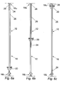
- Fig. 6 there are shown views of the apparatus 10 with the body 20 a) at the bottom of the pole 12; b) in an intermediate position on the pole 12; and c) at an upper end of the pole 12.
- the counterweight 24 is used to balance the weight of the body 20.
- the counterweight 24 is pulled up to the upper end 12u of the pole 12 and the body 20 positioned at the lower end 12l of the pole 12 (as shown in Fig. 6a).
- the plumb line 26 is then attached to the body 20, typically by tying.
- the counterweight 24 is thus used to balance the body 20 and saves the motor and gear assembly therein from wear during use. Additionally, the counterweight 24 will also help to reduce the drain on a battery or the like used to power the motor and gear assembly, as the counterweight 24 aids in movement of the body 20 and thus reduces the amount of power drain from the battery.
- the body 20 is raised to the upper end 12u of the pole 12 (Fig. 6c).
- the counterweight 24 is thus located within the bracket 18u and the accuracy of the apparatus 10 can thus be checked and adjusted if required, as described above.
- the body 20 includes a laser head 30.
- Laser head 30 includes a laser, such as a laser diode or the like, that is used to emit a beam of light. Laser light is very coherent, even after travelling long distances.
- the laser head 30 is preferably interchangeable so that a variety of different types of lasers may be used for different purposes; that is one for longer distances, one for flat (horizontal) beams, etc. It will be appreciated that the laser head 30 can be changed so that the laser beam is a different colour. Thus, a first apparatus 10 can be used in the same vicinity as a second apparatus 10 for a different purpose without affecting one another by changing the colour of the beam.
- the laser head 30 may be provided with two or more lasers that can be operated independently of one another (e.g. they can be provided in a carousel-type arrangement). Thus, two or more different coloured or types of laser can be selected without having to change the laser head 30.
- Laser head 30 is mounted to the body 20 using a mounting plate 32 to facilitate rotational movement thereof.
- the laser head 30 can be rotated around a substantially horizontal axis, as indicated by arrow 34.
- Plate 32 can be freely rotated so that the light emitted by the laser can define an arc or a circle, for example.
- the laser head 30 can be tilted to allow for variations in the diameter of the circle, arc or the like. It will be appreciated that rotation of the laser head 30 about the horizontal axis may be remotely controlled (e.g. by providing the head 30 with a motor and/or gear assembly or the like).
- Plate 32 is advantageously provided with indication means 36 that allows a user to set the laser head 30 at angles between 0° and 360°.
- the indication means 36 preferably comprise radial lines that are spaced around the circumference of plate 32 at various angles. It is also advantageous for the plate 32 to include a locking means (not shown), e.g. a grub screw or the like, to allow the plate 32 to be set at a particular angle (e.g. 45°) .
- Plate 32 is mounted to body 20 using a swivel 38 that allows the laser head 30 to be rotated about a substantially vertical axis, as indicated by arrow 40.
- Swivel 38 preferably allows the head 30 to rotate freely so that the beam emitted by the laser can be used to provide a level on all surrounding walls.
- Swivel 38 may also be provided with a locking means (not shown) to prevent rotation thereof. Again, rotation of the swivel 38 and thus the laser head 30 about the vertical axis can be remotely controlled (e.g. by motorising the swivel 38).
- FIG. 5 there is shown a second embodiment of apparatus 100.
- Apparatus 100 is similar to apparatus 10 (like features being designated with the same reference numerals pre-fixed "1"), but body 120 is configured for manual operation.
- body 120 is provided with a locking means 120l, that may comprise a grub screw, nut and bolt or the like.
- the locking means 120l is tightened to lock the body 120 on the pole 112 at the required location.
- a grub screw is used, the screw is rotated until one end of the screw engages the pole 112, thus locking the body 120 in position.
- the body 120 may be provided with a clamp (not shown) so that tightening of the nut and bolt tightens the clamp on the pole 112.
- the apparatus 100 is set-up and used in a similar way as apparatus 10, and thus has the same advantages.
- mounting plate 32 and/or swivel 38 may be motorised. This would allow the plate 32 and/or swivel 38 to be rotated fast enough to facilitate a substantially continuous line to be shown on the wall surface or the like.
Landscapes
- Engineering & Computer Science (AREA)
- Physics & Mathematics (AREA)
- General Physics & Mathematics (AREA)
- Radar, Positioning & Navigation (AREA)
- Remote Sensing (AREA)
- Architecture (AREA)
- Mechanical Engineering (AREA)
- Civil Engineering (AREA)
- Structural Engineering (AREA)
- Conveying And Assembling Of Building Elements In Situ (AREA)
Abstract
Description
Claims (35)
- Apparatus for providing a reference point or line, the apparatus comprising a body and an elongate member having a longitudinal axis, the body having a laser and being capable of movement substantially parallel to the longitudinal axis of the elongate member.
- Apparatus according to claim 1, wherein the elongate member is adapted to be fixed to a support.
- Apparatus according to any preceding claim, wherein the elongate member is provided with a first bracket for engaging a first supporting structure.
- Apparatus according to claim 3, wherein the elongate member is provided with a second bracket for engaging a second supporting surface.
- Apparatus according to any preceding claim, wherein the elongate member is provided with adjustment means to facilitate adjustment of the length of the elongate member.
- Apparatus according to claim 5, wherein the adjustment means comprises a telescopic or sliding portion of the elongate member.
- Apparatus according to claim 5 or claim 6, wherein the adjustment means includes a locking means.
- Apparatus according to claim 7, wherein the locking means comprises a locking collar and a tightening sleeve.
- Apparatus according to any preceding claim, wherein the elongate member is adapted to be held using one or more guy ropes attached to the member.
- Apparatus according to any preceding claim, wherein the elongate member comprises two or more portions that are coupled together.
- Apparatus according to claim 10, wherein the portions are of different lengths.
- Apparatus according to any preceding claim, wherein the elongate member has a counterweight attached thereto.
- Apparatus according to claim 12, wherein the counterweight is suspended from a plumb line.
- Apparatus according to claim 13, wherein the plumb line is attached at a first end thereof to the body, and at a second end thereof to the counterweight.
- Apparatus according to claim 13 or claim 14, wherein the plumb line passes through or over a pulley provided at an end of the elongate member.
- Apparatus according to any one of claims 13 to 15, wherein the body can be moved substantially parallel to the elongate member by varying the length of the plumb line.
- Apparatus according to any one of claims 13 to 16, wherein the elongate member is provided with a bore in which the plumb line and/or the counterweight can be located.
- Apparatus according to any one of claims 12 to 17, wherein the counterweight engages a portion of the elongate member.
- Apparatus according to any preceding claim, wherein the movement of the body substantially parallel to the longitudinal axis of the elongate member can be remotely controlled.
- Apparatus according to any preceding claim, wherein the body is provided with a motor and gear assembly to move the body substantially parallel to the longitudinal axis of the elongate member.
- Apparatus according to claim 20, wherein the elongate member is provided with engagement means for engagement with the motor and gear assembly provided on the body.
- Apparatus according to any preceding claim, wherein the laser is capable of rotation about a first axis that is substantially parallel to the longitudinal axis of the elongate member.
- Apparatus according to any preceding claim, wherein the laser is capable of rotation about a second axis that is substantially perpendicular to the longitudinal axis of the elongate member.
- Apparatus according to claim 22 or claim 23, wherein the laser can rotate through 360° about the first and/or second axis.
- Apparatus according to any preceding claim, wherein the laser is interchangeable so that a number of different lasers can be used for different functions.
- Apparatus according to any preceding claim, wherein the laser is mounted to the body using a swivel.
- Apparatus according to claim 26, wherein the laser is mounted to the swivel using a mounting plate, the mounting plate being capable of rotation about an axis that is substantially perpendicular to the longitudinal axis of the elongate member.
- Apparatus according to claim 27, wherein the mounting plate is capable of 360° rotation about the axis.
- Apparatus according to claim 27 or claim 28, wherein the mounting plate is provided with indication means.
- Apparatus according to claim 29, wherein the indication means comprises a plurality of lines indicating angular positions of the laser relative to the pole or plate.
- Apparatus according to any one of claims 27 to 30, wherein the mounting plate and/or the body are provided with a locking means to lock the laser at a certain angle.
- A method of providing a reference point or line, the method comprising the steps of providing a body and an elongate member having a longitudinal axis, the body having a laser and being capable of movement substantially parallel to the longitudinal axis of the elongate member; securing the elongate member in a substantially vertical orientation; positioning the laser at a pre-selected position on the elongated member; and actuating the laser.
- A method according to claim 32, wherein the elongate member is secured in a substantially vertical orientation by bracing it between first and second surfaces.
- A method according to claim 33, wherein the first surface comprises a ceiling.
- A method according to claim 33 or claim 34, wherein the second surface comprises a floor.
Applications Claiming Priority (2)
| Application Number | Priority Date | Filing Date | Title |
|---|---|---|---|
| GBGB9929618.8A GB9929618D0 (en) | 1999-12-16 | 1999-12-16 | Level apparatus |
| GB9929618 | 1999-12-16 |
Publications (2)
| Publication Number | Publication Date |
|---|---|
| EP1108981A2 true EP1108981A2 (en) | 2001-06-20 |
| EP1108981A3 EP1108981A3 (en) | 2002-05-08 |
Family
ID=10866352
Family Applications (1)
| Application Number | Title | Priority Date | Filing Date |
|---|---|---|---|
| EP00311224A Withdrawn EP1108981A3 (en) | 1999-12-16 | 2000-12-15 | Apparatus for and a method of providing a reference point or line |
Country Status (3)
| Country | Link |
|---|---|
| US (1) | US6594910B2 (en) |
| EP (1) | EP1108981A3 (en) |
| GB (1) | GB9929618D0 (en) |
Cited By (8)
| Publication number | Priority date | Publication date | Assignee | Title |
|---|---|---|---|---|
| EP1959186A2 (en) | 2007-02-13 | 2008-08-20 | Leica Geosystems AG | Stand with at least three support legs |
| EP2277005A1 (en) * | 2008-05-07 | 2011-01-26 | Robert Bosch GmbH | Mobile measuring system and measuring method |
| EP2277004A1 (en) * | 2008-05-07 | 2011-01-26 | Robert Bosch GmbH | Mobile measuring system and measuring method for measuring profile cuts or contours |
| CN106948605A (en) * | 2017-03-31 | 2017-07-14 | 中国冶集团有限公司 | A kind of assembled laser marked rod device |
| CN110567444A (en) * | 2019-08-01 | 2019-12-13 | 南宁学院 | An intelligent level meter for masonry |
| WO2022062375A1 (en) * | 2020-09-28 | 2022-03-31 | 南京灵雀智能制造有限公司 | Construction pay-off robot with deviation rectifying function and working method therefor |
| US11320263B2 (en) | 2019-01-25 | 2022-05-03 | Stanley Black & Decker Inc. | Laser level system |
| CN118547823A (en) * | 2024-06-20 | 2024-08-27 | 圣晖系统集成集团股份有限公司 | Clean room ceiling and installation method |
Families Citing this family (38)
| Publication number | Priority date | Publication date | Assignee | Title |
|---|---|---|---|---|
| US6256895B1 (en) * | 1998-01-08 | 2001-07-10 | Paul Akers | Laser leveling system, apparatus and method for building construction |
| US6804893B2 (en) * | 2002-06-28 | 2004-10-19 | Black & Decker Inc. | Laser leveling system |
| US7191532B2 (en) * | 2004-08-17 | 2007-03-20 | Eastway Fair Company Limited | Modular tool assembly having a vacuum mounting arrangement |
| US7181854B2 (en) * | 2004-08-17 | 2007-02-27 | Eastway Fair Company Limited | Laser leveling device having a suction mounting arrangement |
| US20060168828A1 (en) * | 2005-01-28 | 2006-08-03 | Brent Dallman | Laser guided work device |
| US7219437B2 (en) * | 2005-01-28 | 2007-05-22 | Brent Dallman | Laser guided work device |
| US7140117B1 (en) * | 2005-06-17 | 2006-11-28 | Weiss Anthony J | Dartboard positioning device and method |
| DE202005015263U1 (en) * | 2005-09-27 | 2006-01-05 | STABILA Messgeräte Gustav Ullrich GmbH | measuring arrangement |
| US7392592B2 (en) | 2005-10-07 | 2008-07-01 | Milwaukee Electric Tool Corporation | Ruggedized laser level |
| US7669341B1 (en) | 2006-01-23 | 2010-03-02 | Kenneth Carazo | Adjustable prism stand/pole |
| US20080062669A1 (en) * | 2006-09-07 | 2008-03-13 | Parel Thomas M | Gravity dial level indicator for line generator |
| US7591075B2 (en) | 2006-09-28 | 2009-09-22 | Techtronic Power Tools Technology Limited | Self-leveling mechanism |
| CN100504334C (en) * | 2006-12-14 | 2009-06-24 | 中国科学院长春光学精密机械与物理研究所 | Method for detecting photoelectric measurement device infrared optical axis azimuth change using hot plummet |
| US7690124B1 (en) * | 2008-01-31 | 2010-04-06 | Bruce Sangeet Henry | Self-supporting stud finder with line-laser |
| US7748127B1 (en) * | 2008-07-21 | 2010-07-06 | Harry Cosimano | Light fixture alignment tool |
| US7886450B1 (en) | 2009-01-04 | 2011-02-15 | Joseph Fiano | Elevated laser beam positioning device |
| US8348072B2 (en) * | 2009-03-20 | 2013-01-08 | Helen Of Troy Limited | Tension-mounted pole caddy |
| DE102010030593A1 (en) * | 2010-06-28 | 2011-12-29 | Hilti Aktiengesellschaft | Device and method for adjusting the height of a stand |
| US8684632B2 (en) * | 2010-12-08 | 2014-04-01 | Laserline Mfg., Inc. | Systems and methods for laying out and installing a solar panel array |
| IT1403591B1 (en) * | 2010-12-21 | 2013-10-31 | Pensieri | STAIRCASE WITH IMPROVED STABILITY |
| US8826554B2 (en) * | 2011-03-29 | 2014-09-09 | Ronald Bariteau | Custom baluster level |
| NL1039289C2 (en) * | 2012-01-12 | 2013-07-15 | Iihan Icoz | METHOD FOR POSING A LASER AND A TRIPOD |
| US9109892B2 (en) * | 2012-06-21 | 2015-08-18 | Eduardo Carbajal | Light-enabled plumb indicator and wall brace device |
| CN105122001B (en) * | 2013-07-29 | 2017-08-11 | 特里伯耶拿有限公司 | For surveying the damping unit of bar and exploration bar including damping unit |
| US9777440B2 (en) * | 2013-09-25 | 2017-10-03 | Harsco Corporation | Systems and methods for use in rail track corrections |
| US9441951B1 (en) * | 2013-11-25 | 2016-09-13 | Amazon Technologies, Inc. | Documenting test room configurations |
| US9692121B2 (en) | 2015-06-25 | 2017-06-27 | Christopher Grabert | Directional-antenna-placement visual aid and method |
| US9808125B2 (en) * | 2015-09-01 | 2017-11-07 | Artika for Living Inc. | Vertically adjustable shower caddy and method for tensioning same |
| US10436586B1 (en) | 2017-09-05 | 2019-10-08 | Drew Davis | Adjustable laser line, level, and square |
| CN108955654B (en) * | 2018-04-11 | 2020-12-22 | 广东省特种设备检测研究院珠海检测院 | A laser positioning method and device for detection of storage tank floor |
| CN111042551B (en) * | 2019-12-20 | 2024-12-13 | 中国建筑第八工程局有限公司 | Retaining wall positioning and outline display equipment and retaining wall positioning method |
| EP4247590A4 (en) | 2020-11-18 | 2025-02-26 | Milwaukee Electric Tool Corporation | Clamp locking mechanism |
| US20220390232A1 (en) * | 2020-12-12 | 2022-12-08 | Graham Procyk | Apparatus for use with a rotary laser level system |
| US20220307835A1 (en) * | 2021-03-29 | 2022-09-29 | Frank Basile | Laser Level Multi-Tool |
| AU2022273776A1 (en) * | 2021-05-14 | 2024-05-30 | Sea Ray Construction LLC | Tool For Measuring Distance |
| JP7570071B2 (en) * | 2021-05-28 | 2024-10-21 | 戸田建設株式会社 | Adjustment set |
| FR3129864B1 (en) * | 2021-12-06 | 2023-12-15 | Pierre Gracia | Device for assisting in tracing a surface using a tracing line |
| IT202300012585A1 (en) * | 2023-06-19 | 2024-12-19 | Frate Giorgio Del | IMPROVED MULTIFUNCTIONAL LASER LEVEL |
Family Cites Families (29)
| Publication number | Priority date | Publication date | Assignee | Title |
|---|---|---|---|---|
| US342303A (en) * | 1886-05-18 | Combined plumb | ||
| US753354A (en) * | 1904-03-01 | Plumb and level | ||
| US688952A (en) * | 1901-05-31 | 1901-12-17 | Carsten Diedrich Janssen | Plumb. |
| US1500639A (en) | 1923-02-12 | 1924-07-08 | John J Rekar | Electric lamp |
| US2245646A (en) * | 1939-06-30 | 1941-06-17 | Lingham J Bullivant | Extension plumb rod |
| US2206530A (en) | 1939-11-18 | 1940-07-02 | George A Duren | Plumb bob adjusting and counterbalance device |
| US3277579A (en) * | 1964-01-13 | 1966-10-11 | Gerald E Murphy | Telescopic vertical level |
| US3328887A (en) * | 1965-10-20 | 1967-07-04 | Donald E Wright | Layout tool |
| US3522658A (en) * | 1968-05-22 | 1970-08-04 | John F Howell | Electrical outlet box locater |
| US3638325A (en) | 1969-10-16 | 1972-02-01 | Albert V Petrik | Vertical alignment gauge |
| US3606713A (en) * | 1969-10-24 | 1971-09-21 | Us Navy | Remote control for collapsible towers |
| BE758240A (en) * | 1969-11-07 | 1971-04-01 | Contraves Italiana Spa | TARGET CAPTURE AND TRACKING OPTICAL POINTER |
| US3775929A (en) * | 1971-06-11 | 1973-12-04 | Laser Alignment | Method for installing ceilings |
| US3922969A (en) * | 1974-02-21 | 1975-12-02 | Canron Inc | Moving projector system |
| US4183667A (en) * | 1977-09-21 | 1980-01-15 | Denton Howard M | Light-ray indicator |
| US4142798A (en) * | 1977-10-14 | 1979-03-06 | Barbee Jr Adron W | Platform laser beam generator support and alignment apparatus and method for using same |
| US4202108A (en) * | 1978-08-04 | 1980-05-13 | Adams Daniel Jr | Apparatus and method for marking points and lines during building construction |
| ATE2580T1 (en) * | 1980-02-01 | 1983-03-15 | Contraves Ag | ARRANGEMENT FOR THE VOLTAGE-FREE BEARING OF A SHAFT FOR THE ELEVATION MOVEMENT OF AN OPTICAL DEVICE. |
| FR2531205A1 (en) * | 1982-07-29 | 1984-02-03 | Commissariat Energie Atomique | LASER STIFFENING DEVICE FOR DIMENSIONAL CONTROL |
| JPS61262611A (en) * | 1985-05-16 | 1986-11-20 | Fujita Corp | Automatic marking device using laser light |
| JPS63279113A (en) * | 1987-05-11 | 1988-11-16 | Toyo Tec Kk | Horizontality/verticality measuring apparatus |
| FR2684496A1 (en) | 1991-11-29 | 1993-06-04 | Comtrad | Alignment laser |
| US5505000A (en) * | 1994-08-30 | 1996-04-09 | Hein-Werner Corporation | Battery powered laser and mount system |
| US5903345A (en) * | 1996-03-01 | 1999-05-11 | Dwbh Ventures Ltd. | Remotely positionable gravity oriented laser scanner |
| US5842282A (en) * | 1996-10-01 | 1998-12-01 | Opcom Inc. | Laser angle adjustment device for laser measuring instruments |
| US5758448A (en) * | 1997-01-02 | 1998-06-02 | Laser Devices, Inc. | Laser system mounting device |
| JPH10318751A (en) * | 1997-05-20 | 1998-12-04 | Nikon Corp | Remote controllable laser projector |
| US6256895B1 (en) * | 1998-01-08 | 2001-07-10 | Paul Akers | Laser leveling system, apparatus and method for building construction |
| US6438854B1 (en) * | 2000-09-15 | 2002-08-27 | Edward J. Kott, Jr. | Center line marking apparatus |
-
1999
- 1999-12-16 GB GBGB9929618.8A patent/GB9929618D0/en not_active Ceased
-
2000
- 2000-12-15 US US09/738,019 patent/US6594910B2/en not_active Expired - Fee Related
- 2000-12-15 EP EP00311224A patent/EP1108981A3/en not_active Withdrawn
Cited By (11)
| Publication number | Priority date | Publication date | Assignee | Title |
|---|---|---|---|---|
| EP1959186A2 (en) | 2007-02-13 | 2008-08-20 | Leica Geosystems AG | Stand with at least three support legs |
| DE102007007041B3 (en) * | 2007-02-13 | 2008-10-02 | Leica Geosystems Ag | Tripod with at least three tripod legs |
| US7669814B2 (en) | 2007-02-13 | 2010-03-02 | Leica Geosystems Ag | Stand with at least three legs |
| EP2277005A1 (en) * | 2008-05-07 | 2011-01-26 | Robert Bosch GmbH | Mobile measuring system and measuring method |
| EP2277004A1 (en) * | 2008-05-07 | 2011-01-26 | Robert Bosch GmbH | Mobile measuring system and measuring method for measuring profile cuts or contours |
| CN106948605A (en) * | 2017-03-31 | 2017-07-14 | 中国冶集团有限公司 | A kind of assembled laser marked rod device |
| CN106948605B (en) * | 2017-03-31 | 2019-01-15 | 中国一冶集团有限公司 | A kind of assembled laser marked rod device |
| US11320263B2 (en) | 2019-01-25 | 2022-05-03 | Stanley Black & Decker Inc. | Laser level system |
| CN110567444A (en) * | 2019-08-01 | 2019-12-13 | 南宁学院 | An intelligent level meter for masonry |
| WO2022062375A1 (en) * | 2020-09-28 | 2022-03-31 | 南京灵雀智能制造有限公司 | Construction pay-off robot with deviation rectifying function and working method therefor |
| CN118547823A (en) * | 2024-06-20 | 2024-08-27 | 圣晖系统集成集团股份有限公司 | Clean room ceiling and installation method |
Also Published As
| Publication number | Publication date |
|---|---|
| US6594910B2 (en) | 2003-07-22 |
| EP1108981A3 (en) | 2002-05-08 |
| GB9929618D0 (en) | 2000-02-09 |
| US20020017028A1 (en) | 2002-02-14 |
Similar Documents
| Publication | Publication Date | Title |
|---|---|---|
| US6594910B2 (en) | Apparatus for and a method of providing a reference point or line | |
| US4470574A (en) | Support structure for building forms | |
| US20130340267A1 (en) | Light-Enabled Plumb Indicator and Wall Brace Device | |
| US6539676B2 (en) | Portable roof anchor | |
| EP3833833B1 (en) | A system for constructing buildings | |
| US8459412B2 (en) | Portable scaffold system | |
| US5114127A (en) | Plumb-align device | |
| US4368800A (en) | Scaffolding apparatus | |
| US7310888B2 (en) | Masonry story pole with adjustable braces | |
| US3463916A (en) | Portable light tower | |
| US5915809A (en) | Masonry column guide | |
| US3348312A (en) | Corner guide system | |
| US6760974B1 (en) | Height determining instrument for poured floors, and method | |
| CA2063095A1 (en) | Adjustable brace | |
| US7051838B1 (en) | Scaffolding system, integral safety rail therefor and methods of making the same | |
| GB2134580A (en) | Bricklayer's guide | |
| US20180305981A1 (en) | Device for the Nivellation of Ladders | |
| US5033710A (en) | Apparatus for holding and operating a hand-held tool | |
| US10612924B2 (en) | Construction device | |
| EP4129886B1 (en) | Metal gantry for a lifting device for transporting materials, method of applciation and uses thereof | |
| US6725971B1 (en) | Pipe jack | |
| US20090194368A1 (en) | Portable roof anchor | |
| US2883241A (en) | Scaffolding accessory | |
| WO1993022619A1 (en) | Vertical alignment apparatus | |
| US6594962B2 (en) | Method and apparatus for mounting a pre-cast panel to a structure |
Legal Events
| Date | Code | Title | Description |
|---|---|---|---|
| PUAI | Public reference made under article 153(3) epc to a published international application that has entered the european phase |
Free format text: ORIGINAL CODE: 0009012 |
|
| AK | Designated contracting states |
Kind code of ref document: A2 Designated state(s): AT BE CH CY DE DK ES FI FR GB GR IE IT LI LU MC NL PT SE TR |
|
| AX | Request for extension of the european patent |
Free format text: AL;LT;LV;MK;RO;SI |
|
| PUAL | Search report despatched |
Free format text: ORIGINAL CODE: 0009013 |
|
| AK | Designated contracting states |
Kind code of ref document: A3 Designated state(s): AT BE CH CY DE DK ES FI FR GB GR IE IT LI LU MC NL PT SE TR |
|
| AX | Request for extension of the european patent |
Free format text: AL;LT;LV;MK;RO;SI |
|
| 17P | Request for examination filed |
Effective date: 20020917 |
|
| AKX | Designation fees paid |
Designated state(s): AT BE CH CY DE DK ES FI FR GB GR IE IT LI LU MC NL PT SE TR |
|
| STAA | Information on the status of an ep patent application or granted ep patent |
Free format text: STATUS: THE APPLICATION IS DEEMED TO BE WITHDRAWN |
|
| 18D | Application deemed to be withdrawn |
Effective date: 20060201 |