EP1958868B1 - Apparatus and method for LNG carrier propulsion - Google Patents
Apparatus and method for LNG carrier propulsion Download PDFInfo
- Publication number
- EP1958868B1 EP1958868B1 EP07007424A EP07007424A EP1958868B1 EP 1958868 B1 EP1958868 B1 EP 1958868B1 EP 07007424 A EP07007424 A EP 07007424A EP 07007424 A EP07007424 A EP 07007424A EP 1958868 B1 EP1958868 B1 EP 1958868B1
- Authority
- EP
- European Patent Office
- Prior art keywords
- gas
- boil
- propulsion
- electric motor
- diesel engine
- Prior art date
- Legal status (The legal status is an assumption and is not a legal conclusion. Google has not performed a legal analysis and makes no representation as to the accuracy of the status listed.)
- Not-in-force
Links
Images


Classifications
-
- G—PHYSICS
- G06—COMPUTING OR CALCULATING; COUNTING
- G06F—ELECTRIC DIGITAL DATA PROCESSING
- G06F13/00—Interconnection of, or transfer of information or other signals between, memories, input/output devices or central processing units
- G06F13/38—Information transfer, e.g. on bus
- G06F13/382—Information transfer, e.g. on bus using universal interface adapter
-
- B—PERFORMING OPERATIONS; TRANSPORTING
- B63—SHIPS OR OTHER WATERBORNE VESSELS; RELATED EQUIPMENT
- B63J—AUXILIARIES ON VESSELS
- B63J99/00—Subject matter not provided for in other groups of this subclass
-
- B—PERFORMING OPERATIONS; TRANSPORTING
- B63—SHIPS OR OTHER WATERBORNE VESSELS; RELATED EQUIPMENT
- B63H—MARINE PROPULSION OR STEERING
- B63H21/00—Use of propulsion power plant or units on vessels
- B63H21/20—Use of propulsion power plant or units on vessels the vessels being powered by combinations of different types of propulsion units
-
- B—PERFORMING OPERATIONS; TRANSPORTING
- B63—SHIPS OR OTHER WATERBORNE VESSELS; RELATED EQUIPMENT
- B63J—AUXILIARIES ON VESSELS
- B63J99/00—Subject matter not provided for in other groups of this subclass
- B63J2099/001—Burning of transported goods, e.g. fuel, boil-off or refuse
- B63J2099/003—Burning of transported goods, e.g. fuel, boil-off or refuse of cargo oil or fuel, or of boil-off gases, e.g. for propulsive purposes
-
- G—PHYSICS
- G06—COMPUTING OR CALCULATING; COUNTING
- G06F—ELECTRIC DIGITAL DATA PROCESSING
- G06F2212/00—Indexing scheme relating to accessing, addressing or allocation within memory systems or architectures
- G06F2212/21—Employing a record carrier using a specific recording technology
- G06F2212/214—Solid state disk
- G06F2212/2146—Solid state disk being detachable, e.g.. USB memory
-
- G—PHYSICS
- G06—COMPUTING OR CALCULATING; COUNTING
- G06F—ELECTRIC DIGITAL DATA PROCESSING
- G06F2213/00—Indexing scheme relating to interconnection of, or transfer of information or other signals between, memories, input/output devices or central processing units
- G06F2213/0042—Universal serial bus [USB]
-
- Y—GENERAL TAGGING OF NEW TECHNOLOGICAL DEVELOPMENTS; GENERAL TAGGING OF CROSS-SECTIONAL TECHNOLOGIES SPANNING OVER SEVERAL SECTIONS OF THE IPC; TECHNICAL SUBJECTS COVERED BY FORMER USPC CROSS-REFERENCE ART COLLECTIONS [XRACs] AND DIGESTS
- Y02—TECHNOLOGIES OR APPLICATIONS FOR MITIGATION OR ADAPTATION AGAINST CLIMATE CHANGE
- Y02T—CLIMATE CHANGE MITIGATION TECHNOLOGIES RELATED TO TRANSPORTATION
- Y02T70/00—Maritime or waterways transport
- Y02T70/50—Measures to reduce greenhouse gas emissions related to the propulsion system
-
- Y—GENERAL TAGGING OF NEW TECHNOLOGICAL DEVELOPMENTS; GENERAL TAGGING OF CROSS-SECTIONAL TECHNOLOGIES SPANNING OVER SEVERAL SECTIONS OF THE IPC; TECHNICAL SUBJECTS COVERED BY FORMER USPC CROSS-REFERENCE ART COLLECTIONS [XRACs] AND DIGESTS
- Y02—TECHNOLOGIES OR APPLICATIONS FOR MITIGATION OR ADAPTATION AGAINST CLIMATE CHANGE
- Y02T—CLIMATE CHANGE MITIGATION TECHNOLOGIES RELATED TO TRANSPORTATION
- Y02T70/00—Maritime or waterways transport
- Y02T70/50—Measures to reduce greenhouse gas emissions related to the propulsion system
- Y02T70/5218—Less carbon-intensive fuels, e.g. natural gas, biofuels
Definitions
- the present invention relates generally to an apparatus and method for LNG carrier propulsion, and more particularly to an apparatus comprising a boil-off gas re-liquefaction apparatus, and a method for propelling an LNG carrier.
- liquefied natural gas is produced by cooling natural gas into a cryogenic liquid state at a production terminal and transported by LNG carriers to distant locations where it is to be regasified.
- LNG Since the liquefaction of natural gas occurs at a cryogenic temperature of approximately -163 °C at ambient pressure, LNG is likely to be vaporized if the temperature of LNG increases above -163 °C at ambient pressure.
- an LNG storage tank for the LNG carrier is equipped with thermal insulation structure, it is impossible to completely prevent heat ingress to LNG through the storage tank, and as a result, LNG is consistently vaporized and boil-off gas is generated in the LNG storage tank during LNG transportation.
- a conventional LNG carrier employs a steam turbine propulsion system, which is driven by steam obtained by burning boil-off gas in a boiler.
- a steam turbine propulsion system has a drawback of low propulsion efficiency.
- diesel engine propulsion with a re-liquefaction system which has a boil-off gas re-liquefaction apparatus installed in the LNG carrier to return boil-off gas back to the storage tank and includes a diesel engine having high propulsion efficiency as the main propulsion source.
- the LNG carriers are required to have countermeasures against emergencies, such as the malfunction of main diesel engines in the diesel engine propulsion system. Furthermore, since it is necessary to install two main diesel engines in the prior art, the diesel engine propulsion system has problems in that the construction of an LNG carrier is complicated and initial and maintenance costs are increased.
- the document EP-A1-1 561 683 discloses a barge arrangement comprising a barge unit provided with a load carrying facility and a tug unit provided with a propulsion system.
- a propulsion apparatus for an LNG carrier comprising a boil-off gas re-liquefaction apparatus for re-liquefying boil-off gas generated in an LNG storage tank to return the re-liquefied boil-off gas back to the LNG storage tank, the apparatus comprising: a single main diesel engine; a propulsion shaft separably connected to the main diesel engine; and an electric motor for propulsion separably connected to the propulsion shaft and supplied with power intended for operation of the boil-off gas re-liquefaction apparatus.
- a method for propelling an LNG carrier comprising a boil-off gas re-liquefaction apparatus for re-liquefying boil-off gas generated in an LNG storage tank to return the re-liquefied boil-off gas back to the LNG storage tank, comprising: propelling the LNG carrier with power from a single main diesel engine during normal operation, and, in case of main diesel engine malfunction, propelling the LNG carrier by the electric motor with power intended for boil-off gas re-liquefaction apparatus while disconnecting power transmission from the main engine.
- Fig. 1 is a schematic view illustrating a propulsion apparatus for an LNG carrier according to an exemplary embodiment of the present invention.
- a propulsion apparatus for LNG carriers according to the exemplary embodiment comprises a boil-off gas re-liquefaction apparatus 200 for re-liquefying boil-off gas generated in an LNG storage tank 1 and returning it back to the LNG storage tank 1.
- the propulsion apparatus of the LNG carrier comprises a main diesel engine 10, a propulsion shaft 20, a propeller 30, and an electric motor 40 for propulsion.
- the LNG carrier comprises only a single main diesel engine 10.
- the propulsion shaft 20 is separably connected to the main diesel engine 10 with a clutch 50 disposed between the propulsion shaft 20 and a driving shaft 11 of the main diesel engine 10.
- the propeller 30 for propelling the LNG carrier is connected to an end of the propulsion shaft 20.
- the electric motor 40 for propulsion is separably connected to the propulsion shaft 20 with another clutch 60 disposed between the propulsion shaft 20 and a driving shaft 41 of the electric motor 40.
- a reduction gear 70 is disposed between the driving shaft 41 of the electric motor 40 and the propulsion shaft 20. The reduction gear 70 is connected to the propulsion shaft 20 and reduces the rotating speed of the driving shaft 41 of the electric motor 40.
- the electric motor 40 for propulsion is supplied with power intended for operation of the boil-off gas re-liquefaction apparatus 200 supplied from a generator 100, and is connected in parallel to two inverters 110 for the boil-off gas re-liquefaction apparatus 200.
- the electric motor 40 for propulsion is connected in parallel to the two inverters 110, it is possible to increase the capability of the electric motor 40 twice.
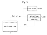
- the LNG carrier has a gas burner 300 disposed downstream of the LNG storage tank 1.
- a single main diesel engine 10 is connected to a propulsion shaft 20 during normal operation of the main diesel engine 10.
- the main diesel engine 10 is disconnected from the propulsion shaft 20, and at the same time, the electric motor 40, to which power intended for operation of the boil-off gas re-liquefaction apparatus 200 is supplied from a generator 100, is connected to the propulsion shaft 20.
- a clutch 50 is connected between a driving shaft 11 and the propulsion shaft 20, whereas upon malfunction of the main diesel engine 10, the clutch 50 is released from connection between the driving shaft 11 and the propulsion shaft 20 while a clutch 60 is connected between a driving shaft 41 of the electric motor 40 and the propulsion shaft 20.
- boil-off gas generated in an LNG storage tank 1 is routed to a gas combustion unit or gas burner 300 and burned safely without increasing the storage tank pressure.
- the propulsion apparatus and method according to the invention is configured to use an electric motor for propulsion, to which power intended for operation of a boil-off gas re-liquefaction apparatus is supplied, upon malfunction of a main diesel engine, it is possible to promptly cope with emergencies caused by the malfunction of the main diesel engine even though only the single main diesel engine is installed in the propulsion apparatus.
- inverters for the boil-off gas re-liquefaction apparatus can be used as an inverter to drive the electric motor for propulsion upon the emergencies, a separate inverter system is not required for the electric motor, thereby reducing initial installation costs.
Landscapes
- Engineering & Computer Science (AREA)
- Chemical & Material Sciences (AREA)
- Combustion & Propulsion (AREA)
- Mechanical Engineering (AREA)
- Ocean & Marine Engineering (AREA)
- Theoretical Computer Science (AREA)
- Physics & Mathematics (AREA)
- General Engineering & Computer Science (AREA)
- General Physics & Mathematics (AREA)
- Filling Or Discharging Of Gas Storage Vessels (AREA)
Description
- The present invention relates generally to an apparatus and method for LNG carrier propulsion, and more particularly to an apparatus comprising a boil-off gas re-liquefaction apparatus, and a method for propelling an LNG carrier.
- Generally, liquefied natural gas (LNG) is produced by cooling natural gas into a cryogenic liquid state at a production terminal and transported by LNG carriers to distant locations where it is to be regasified.
- Since the liquefaction of natural gas occurs at a cryogenic temperature of approximately -163 °C at ambient pressure, LNG is likely to be vaporized if the temperature of LNG increases above -163 °C at ambient pressure. Although an LNG storage tank for the LNG carrier is equipped with thermal insulation structure, it is impossible to completely prevent heat ingress to LNG through the storage tank, and as a result, LNG is consistently vaporized and boil-off gas is generated in the LNG storage tank during LNG transportation.
- A conventional LNG carrier employs a steam turbine propulsion system, which is driven by steam obtained by burning boil-off gas in a boiler. However, such a steam turbine propulsion system has a drawback of low propulsion efficiency.
- On the other hand, in the case where boil-off gas is not used as fuel for propulsion of an LNG carrier, it is possible to increase the economic values of the boil-off gas by recycling it back to the storage tank. For this purpose, diesel engine propulsion with a re-liquefaction system has been developed, which has a boil-off gas re-liquefaction apparatus installed in the LNG carrier to return boil-off gas back to the storage tank and includes a diesel engine having high propulsion efficiency as the main propulsion source.
- Especially for LNG carriers, to maintain the high reliability, the LNG carriers are required to have countermeasures against emergencies, such as the malfunction of main diesel engines in the diesel engine propulsion system. Furthermore, since it is necessary to install two main diesel engines in the prior art, the diesel engine propulsion system has problems in that the construction of an LNG carrier is complicated and initial and maintenance costs are increased.
- The document
EP-A1-1 561 683 discloses a barge arrangement comprising a barge unit provided with a load carrying facility and a tug unit provided with a propulsion system. - Inter alia, it is an object of the invention to increase, in an apparatus comprising a boil-off gas re-liquefaction apparatus, the capability of an electric motor.
- According to the invention, there are provided an apparatus, and a method for propelling an LNG carrier as defined by the independent claims. Further advantageous features are comprised in the subclaims.
- In accordance with an aspect of the present invention, there is provided a propulsion apparatus for an LNG carrier comprising a boil-off gas re-liquefaction apparatus for re-liquefying boil-off gas generated in an LNG storage tank to return the re-liquefied boil-off gas back to the LNG storage tank, the apparatus comprising: a single main diesel engine; a propulsion shaft separably connected to the main diesel engine; and an electric motor for propulsion separably connected to the propulsion shaft and supplied with power intended for operation of the boil-off gas re-liquefaction apparatus.
- In accordance with another aspect of the present invention, a method for propelling an LNG carrier comprising a boil-off gas re-liquefaction apparatus for re-liquefying boil-off gas generated in an LNG storage tank to return the re-liquefied boil-off gas back to the LNG storage tank is provided, comprising: propelling the LNG carrier with power from a single main diesel engine during normal operation, and, in case of main diesel engine malfunction, propelling the LNG carrier by the electric motor with power intended for boil-off gas re-liquefaction apparatus while disconnecting power transmission from the main engine.
- The above and other objects, features and advantages of the present invention will become apparent from the following description of preferred embodiments given in conjunction with the accompanying drawings, in which:
-
Fig. 1 is a schematic view illustrating a propulsion apparatus for an LNG carrier according to an exemplary embodiment of the present invention; -
Fig. 2 is a schematic view illustrating the supply of power to an electric motor for propulsion in the propulsion apparatus for the LNG carrier according to the exemplary embodiment of the present invention; and -
Fig. 3 is a schematic diagram illustrating a process of treating boil-off gas in the LNG carrier according to the exemplary embodiment of the present invention. - Exemplary embodiments of the present invention will be described in detail with reference to the accompanying drawings hereinafter.
-
Fig. 1 is a schematic view illustrating a propulsion apparatus for an LNG carrier according to an exemplary embodiment of the present invention. As illustrated inFig. 3 , a propulsion apparatus for LNG carriers according to the exemplary embodiment comprises a boil-offgas re-liquefaction apparatus 200 for re-liquefying boil-off gas generated in an LNG storage tank 1 and returning it back to the LNG storage tank 1. - As illustrated in
Fig. 1 , the propulsion apparatus of the LNG carrier according to the exemplary embodiment comprises amain diesel engine 10, apropulsion shaft 20, apropeller 30, and anelectric motor 40 for propulsion. - According to this embodiment, the LNG carrier comprises only a single
main diesel engine 10. - The
propulsion shaft 20 is separably connected to themain diesel engine 10 with aclutch 50 disposed between thepropulsion shaft 20 and adriving shaft 11 of themain diesel engine 10. - The
propeller 30 for propelling the LNG carrier is connected to an end of thepropulsion shaft 20. - Further, the
electric motor 40 for propulsion is separably connected to thepropulsion shaft 20 with anotherclutch 60 disposed between thepropulsion shaft 20 and adriving shaft 41 of theelectric motor 40. Additionally, areduction gear 70 is disposed between thedriving shaft 41 of theelectric motor 40 and thepropulsion shaft 20. Thereduction gear 70 is connected to thepropulsion shaft 20 and reduces the rotating speed of thedriving shaft 41 of theelectric motor 40. - As illustrated in
Fig. 2 , theelectric motor 40 for propulsion is supplied with power intended for operation of the boil-offgas re-liquefaction apparatus 200 supplied from agenerator 100, and is connected in parallel to twoinverters 110 for the boil-offgas re-liquefaction apparatus 200. As such, when theelectric motor 40 for propulsion is connected in parallel to the twoinverters 110, it is possible to increase the capability of theelectric motor 40 twice. - In addition, it is necessary in the prior art to employ a separate inverter for speed control of the
electric motor 40. According to the invention, however, since the inverters for the boil-off gas re-liquefaction apparatus are used as an inverter for the electric motor for propulsion, it is not necessary to add a separate electrical apparatus for the speed control of the electric motor. - As illustrated in
Fig. 3 , the LNG carrier has agas burner 300 disposed downstream of the LNG storage tank 1. - Next, a method for propelling an LNG carrier using the propulsion apparatus according to the present invention is described.
- In the method for propelling the LNG carrier according to the present invention, a single
main diesel engine 10 is connected to apropulsion shaft 20 during normal operation of themain diesel engine 10. On the other hand, upon malfunction of themain diesel engine 10, themain diesel engine 10 is disconnected from thepropulsion shaft 20, and at the same time, theelectric motor 40, to which power intended for operation of the boil-offgas re-liquefaction apparatus 200 is supplied from agenerator 100, is connected to thepropulsion shaft 20. Here, during the normal operation of themain diesel engine 10, aclutch 50 is connected between adriving shaft 11 and thepropulsion shaft 20, whereas upon malfunction of themain diesel engine 10, theclutch 50 is released from connection between thedriving shaft 11 and thepropulsion shaft 20 while aclutch 60 is connected between adriving shaft 41 of theelectric motor 40 and thepropulsion shaft 20. - Upon malfunction of the
main diesel engine 10, power supplied from thegenerator 100 to a boil-offgas re-liquefaction apparatus 200 is cut off to stop operation of the boil-offgas re-liquefaction apparatus 200, and power intended for operation of the boil-offgas re-liquefaction apparatus 200 is supplied to theelectric motor 40 for propulsion, so that theelectric motor 40 is driven. - In the case where the operation of the boil-off
gas re-liquefaction apparatus 200 is stopped, boil-off gas generated in an LNG storage tank 1 is routed to a gas combustion unit orgas burner 300 and burned safely without increasing the storage tank pressure. - As apparent from the above, since the propulsion apparatus and method according to the invention is configured to use an electric motor for propulsion, to which power intended for operation of a boil-off gas re-liquefaction apparatus is supplied, upon malfunction of a main diesel engine, it is possible to promptly cope with emergencies caused by the malfunction of the main diesel engine even though only the single main diesel engine is installed in the propulsion apparatus.
- Further, according to the invention, since inverters for the boil-off gas re-liquefaction apparatus can be used as an inverter to drive the electric motor for propulsion upon the emergencies, a separate inverter system is not required for the electric motor, thereby reducing initial installation costs.
- Although particular embodiments of the present invention have been shown and described herein, it should be understood that various modifications, variations or corrections may readily occur to those skilled in the art, and thus, the description and drawings herein should be interpreted by way of illustrative purpose without limiting the scope of the present invention.
Claims (7)
- An apparatus comprising:a boil-off gas re-liquefaction apparatus (200) for re-liquefying boil-off gas generated in an LNG storage tank to return the re-liquefied boil-off gas back to the LNG storage tank,
a single main diesel engine (10);
a propulsion shaft separably connected to the main diesel engine (10); and
an electric motor (40) for propulsion separably connected to the propulsion shaft; and a generator to supply power to the boil-off gas re-liquefaction apparatus (200) during normal operation of the diesel engine (10), the system adapted such that upon malfunction of the diesel engine, the power supplied to the boil-off gas re-liquefaction apparatus (200) is cut off, and instead is provided to the electric motor (40), wherein the electric motor (40) is connected in parallel to a plurality of inverters for the boil-off gas re-liquefaction apparatus. - The apparatus according to claim 1, further comprising:a clutch between a driving shaft of the main diesel engine (10) and the propulsion shaft.
- The apparatus according to claim 1, further comprising:a clutch between a driving shaft of the electric motor for propulsion and the propulsion shaft.
- The apparatus according to claim 3, further comprising:a reduction gear between the driving shaft of the electric motor and the propulsion shaft.
- The apparatus according to claim 1, wherein the electric motor is connected in parallel to two inverters for the boil-off gas re-liquefaction apparatus.
- The apparatus according to claim 1, further comprising an LNG carrier that has a gas burner to incinerate the boil-off gas.
- A method for propelling an LNG carrier comprising a boil-off gas re-liquefaction apparatus (200) for re-liquefying boil-off gas generated in an LNG storage tank to return the re-liquefied boil-off gas back to the LNG storage tank, the method comprising:propelling the LNG carrier with power from a single main diesel engine (10) during normal operation of the main diesel engine, wherein upon malfunction of the diesel engine, power supplied to the boil-off gas re-liquefaction apparatus from a generator is cut off, and instead is provided to an electric motor (40) for propelling the LNG carrier, and wherein the power intended for operation of the boil-off gas re-liquefaction apparatus is supplied to the electric motor for propulsion through a plurality of inverters connected in parallel.
Applications Claiming Priority (1)
| Application Number | Priority Date | Filing Date | Title |
|---|---|---|---|
| KR1020070005338A KR100804965B1 (en) | 2007-01-17 | 2007-01-17 | Propulsion device and method of LG carrier |
Publications (2)
| Publication Number | Publication Date |
|---|---|
| EP1958868A1 EP1958868A1 (en) | 2008-08-20 |
| EP1958868B1 true EP1958868B1 (en) | 2013-01-02 |
Family
ID=38179779
Family Applications (1)
| Application Number | Title | Priority Date | Filing Date |
|---|---|---|---|
| EP07007424A Not-in-force EP1958868B1 (en) | 2007-01-17 | 2007-04-11 | Apparatus and method for LNG carrier propulsion |
Country Status (6)
| Country | Link |
|---|---|
| US (1) | US7793502B2 (en) |
| EP (1) | EP1958868B1 (en) |
| JP (1) | JP4563420B2 (en) |
| KR (1) | KR100804965B1 (en) |
| CN (1) | CN101224786B (en) |
| WO (1) | WO2008088102A1 (en) |
Families Citing this family (18)
| Publication number | Priority date | Publication date | Assignee | Title |
|---|---|---|---|---|
| DE102008005351B4 (en) | 2008-01-21 | 2018-08-23 | Renk Ag | Torque transmission device for a ship |
| DE102008061951A1 (en) * | 2008-12-12 | 2010-06-17 | Renk Ag | Marine propulsion system |
| JP4980391B2 (en) * | 2009-03-31 | 2012-07-18 | 三井造船株式会社 | Marine power system |
| FR2949751B1 (en) * | 2009-09-10 | 2015-05-29 | Nanni Ind | HYBRID MOTORING DEVICE OF A NAVIGATING STRUCTURE |
| FR2949753B1 (en) * | 2009-09-10 | 2015-04-17 | Nanni Ind | DEVICE FOR GENERATING CURRENT AND / OR ELECTRIC MOTORIZATION ON BOARD A NAVIGATING STRUCTURE |
| KR100961869B1 (en) | 2009-10-16 | 2010-06-09 | 대우조선해양 주식회사 | Ship for running alternatively a liquified gas fuelled main drive engine or a liquified gas fuelled generator engine |
| NO332138B2 (en) * | 2009-11-09 | 2016-04-11 | Rolls Royce Marine As Power Electric Systems Bergen | Hybrid propulsion system for a vessel |
| KR101258941B1 (en) * | 2010-12-01 | 2013-04-29 | 삼성중공업 주식회사 | Ship having hybrid propulsion device |
| CN102120488A (en) * | 2011-03-07 | 2011-07-13 | 上海海事大学 | Electric propulsion system for hybrid power boats and implementation method thereof |
| TW201343478A (en) * | 2012-04-20 | 2013-11-01 | Ship & Ocean Ind R & D Ct | Dual motive power system of a ship and operating method thereof |
| US8850803B2 (en) | 2012-12-10 | 2014-10-07 | Caterpillar Inc. | Auxiliary power and emission-control system using vented gaseous fuel recovery and method |
| JP6290533B2 (en) * | 2012-12-10 | 2018-03-07 | 三菱重工業株式会社 | Marine propulsion system and operation method thereof |
| US9255664B2 (en) * | 2012-12-24 | 2016-02-09 | General Electric Company | Cryogenic fuel system with auxiliary power provided by boil-off gas |
| KR102179194B1 (en) * | 2015-06-09 | 2020-11-16 | 현대중공업 주식회사 | Vessel having Gas Treatment System |
| JP6957165B2 (en) | 2017-02-28 | 2021-11-02 | 三菱重工マリンマシナリ株式会社 | Boiler and boiler system and how to operate the boiler |
| KR102691669B1 (en) * | 2021-12-14 | 2024-08-06 | 대한민국 | Hybrid Barn Ventilator |
| KR102680889B1 (en) | 2021-12-23 | 2024-07-03 | 효성중공업 주식회사 | Hybrid power transmission device for ship |
| KR102680890B1 (en) | 2021-12-23 | 2024-07-03 | 효성중공업 주식회사 | Hybrid power transmission device for ship |
Family Cites Families (20)
| Publication number | Priority date | Publication date | Assignee | Title |
|---|---|---|---|---|
| US3565201A (en) * | 1969-02-07 | 1971-02-23 | Lng Services | Cryogenic fuel system for land vehicle power plant |
| NL7600308A (en) * | 1975-02-07 | 1976-08-10 | Sulzer Ag | METHOD AND EQUIPMENT FOR THE VAPORIZATION AND HEATING OF LIQUID NATURAL GAS. |
| JPS5587698A (en) | 1978-12-25 | 1980-07-02 | Mitsubishi Heavy Ind Ltd | Propulsion system by variable pitch propeller |
| JPS57179589U (en) * | 1981-05-11 | 1982-11-13 | ||
| JPH0654101B2 (en) * | 1987-06-02 | 1994-07-20 | 三菱重工業株式会社 | Gas-fired diesel engine gas supply system |
| SE464529B (en) * | 1988-10-31 | 1991-05-06 | Gunnar Haeggstroem | DRIVING DEVICE FOR MOTOR VEHICLES, SPECIFIC BUSES |
| JPH0446892A (en) * | 1990-06-12 | 1992-02-17 | Mitsubishi Heavy Ind Ltd | Propulsion device for lng transport vessel |
| DE4432483A1 (en) * | 1994-09-13 | 1996-03-14 | Blohm Voss Ag | Auxiliary drive for marine ship with diesel main engine driving propeller via shaft system |
| JPH08230785A (en) * | 1995-02-23 | 1996-09-10 | Ishikawajima Harima Heavy Ind Co Ltd | A ship with an auxiliary electric propulsion device |
| DZ2535A1 (en) * | 1997-06-20 | 2003-01-08 | Exxon Production Research Co | Advanced process for liquefying natural gas. |
| MY117066A (en) * | 1998-10-22 | 2004-04-30 | Exxon Production Research Co | Process for removing a volatile component from natural gas |
| MY115510A (en) | 1998-12-18 | 2003-06-30 | Exxon Production Research Co | Method for displacing pressurized liquefied gas from containers |
| JP3790393B2 (en) * | 1999-11-05 | 2006-06-28 | 大阪瓦斯株式会社 | Cargo tank pressure control device and pressure control method for LNG carrier |
| US6672104B2 (en) * | 2002-03-28 | 2004-01-06 | Exxonmobil Upstream Research Company | Reliquefaction of boil-off from liquefied natural gas |
| KR200287600Y1 (en) * | 2002-05-31 | 2002-08-30 | 삼성중공업 주식회사 | Boil off gas dumping system |
| KR100598699B1 (en) * | 2002-06-05 | 2006-07-11 | 삼성중공업 주식회사 | Power propulsion system for LAN ships |
| JP4228608B2 (en) * | 2002-07-23 | 2009-02-25 | 株式会社Ihi | Propulsion device for liquefied gas carrier |
| US7219502B2 (en) * | 2003-08-12 | 2007-05-22 | Excelerate Energy Limited Partnership | Shipboard regasification for LNG carriers with alternate propulsion plants |
| FI116972B (en) | 2004-02-09 | 2006-04-28 | Waertsilae Finland Oy | Barge arrangement, barge unit and tug unit |
| GB0424967D0 (en) | 2004-11-12 | 2004-12-15 | Hamworthy Combustion Eng Ltd | Incinerator for boil-off gas |
-
2007
- 2007-01-17 KR KR1020070005338A patent/KR100804965B1/en active Active
- 2007-02-13 WO PCT/KR2007/000764 patent/WO2008088102A1/en not_active Ceased
- 2007-04-11 EP EP07007424A patent/EP1958868B1/en not_active Not-in-force
- 2007-04-13 JP JP2007105761A patent/JP4563420B2/en not_active Expired - Fee Related
- 2007-04-26 CN CN2007100969941A patent/CN101224786B/en not_active Expired - Fee Related
- 2007-10-16 US US11/873,318 patent/US7793502B2/en not_active Expired - Fee Related
Also Published As
| Publication number | Publication date |
|---|---|
| US7793502B2 (en) | 2010-09-14 |
| US20080209908A1 (en) | 2008-09-04 |
| JP4563420B2 (en) | 2010-10-13 |
| KR100804965B1 (en) | 2008-02-20 |
| CN101224786A (en) | 2008-07-23 |
| CN101224786B (en) | 2012-08-08 |
| JP2008174207A (en) | 2008-07-31 |
| EP1958868A1 (en) | 2008-08-20 |
| WO2008088102A1 (en) | 2008-07-24 |
Similar Documents
| Publication | Publication Date | Title |
|---|---|---|
| US7793502B2 (en) | Apparatus and method for liquefied natural gas carrier propulsion | |
| US9428256B2 (en) | Ship alternatively running fuel gas main drive engine and fuel gas generator engine | |
| CN104024619B (en) | Fuel combination supply system and method for the engine of ship | |
| KR101521143B1 (en) | Mixed propulsion system | |
| JP6220432B2 (en) | Method and system for electric steam supply system | |
| JP4228608B2 (en) | Propulsion device for liquefied gas carrier | |
| EP2808248B1 (en) | Method of converting steam turbine-powered lng carriers | |
| EP3252289B1 (en) | System and method for controlling fuel supply of ship engine | |
| KR101775056B1 (en) | Method for operating floating-type structure having power storage device | |
| KR20190042963A (en) | Combined Gas turbine Electric And Steam System Using Duel Fuel Boiler | |
| JPS5833593A (en) | Compound energy conservation equipment for liquefied-gas ship | |
| KR102589458B1 (en) | Hybrid generation and propulsion system and method for a vessel | |
| KR100922007B1 (en) | How to Operate an LG Carrier | |
| KR20110127505A (en) | Floating Structure with Electric Storage | |
| KR20240065127A (en) | Hybrid combined cycle power system | |
| JP2007223358A (en) | Marine propulsion plant, ship equipped with the same and method for controlling marine propulsion plant | |
| KR20230059560A (en) | Hybrid generation and propulsion system and method for a vessel | |
| JP2018024279A (en) | Marine power supply system | |
| KR101629363B1 (en) | Electric power producing system using waste heat recovery | |
| Bassam | Dual Fuel Electric System as an alternative Propulsion for LNG Carrier | |
| KR20220155769A (en) | Power supply apparatur for vessel | |
| KR20230059557A (en) | Ship | |
| KR20200048093A (en) | Gas Treatment System And Method For Ship | |
| KR20130000937A (en) | Pressure relief device of fuel gas tank using boiler | |
| Slatter | Marine and Industrial Uses of the Proteus and Olympus Engines |
Legal Events
| Date | Code | Title | Description |
|---|---|---|---|
| PUAI | Public reference made under article 153(3) epc to a published international application that has entered the european phase |
Free format text: ORIGINAL CODE: 0009012 |
|
| 17P | Request for examination filed |
Effective date: 20070411 |
|
| AK | Designated contracting states |
Kind code of ref document: A1 Designated state(s): AT BE BG CH CY CZ DE DK EE ES FI FR GB GR HU IE IS IT LI LT LU LV MC MT NL PL PT RO SE SI SK TR |
|
| AX | Request for extension of the european patent |
Extension state: AL BA HR MK RS |
|
| 17Q | First examination report despatched |
Effective date: 20090320 |
|
| AKX | Designation fees paid |
Designated state(s): AT BE BG CH CY CZ DE DK EE ES FI FR GB GR HU IE IS IT LI LT LU LV MC MT NL PL PT RO SE SI SK TR |
|
| REG | Reference to a national code |
Ref country code: DE Ref legal event code: R079 Ref document number: 602007027721 Country of ref document: DE Free format text: PREVIOUS MAIN CLASS: B63H0021120000 Ipc: B63H0021200000 |
|
| GRAP | Despatch of communication of intention to grant a patent |
Free format text: ORIGINAL CODE: EPIDOSNIGR1 |
|
| RIC1 | Information provided on ipc code assigned before grant |
Ipc: B63H 21/20 20060101AFI20120601BHEP |
|
| GRAC | Information related to communication of intention to grant a patent modified |
Free format text: ORIGINAL CODE: EPIDOSCIGR1 |
|
| GRAS | Grant fee paid |
Free format text: ORIGINAL CODE: EPIDOSNIGR3 |
|
| GRAA | (expected) grant |
Free format text: ORIGINAL CODE: 0009210 |
|
| AK | Designated contracting states |
Kind code of ref document: B1 Designated state(s): AT BE BG CH CY CZ DE DK EE ES FI FR GB GR HU IE IS IT LI LT LU LV MC MT NL PL PT RO SE SI SK TR |
|
| REG | Reference to a national code |
Ref country code: GB Ref legal event code: FG4D |
|
| REG | Reference to a national code |
Ref country code: CH Ref legal event code: EP Ref country code: AT Ref legal event code: REF Ref document number: 591451 Country of ref document: AT Kind code of ref document: T Effective date: 20130115 |
|
| REG | Reference to a national code |
Ref country code: IE Ref legal event code: FG4D |
|
| REG | Reference to a national code |
Ref country code: DE Ref legal event code: R096 Ref document number: 602007027721 Country of ref document: DE Effective date: 20130228 |
|
| REG | Reference to a national code |
Ref country code: AT Ref legal event code: MK05 Ref document number: 591451 Country of ref document: AT Kind code of ref document: T Effective date: 20130102 |
|
| REG | Reference to a national code |
Ref country code: GR Ref legal event code: EP Ref document number: 20130400504 Country of ref document: GR Effective date: 20130418 |
|
| REG | Reference to a national code |
Ref country code: NL Ref legal event code: VDEP Effective date: 20130102 |
|
| PG25 | Lapsed in a contracting state [announced via postgrant information from national office to epo] |
Ref country code: SI Free format text: LAPSE BECAUSE OF FAILURE TO SUBMIT A TRANSLATION OF THE DESCRIPTION OR TO PAY THE FEE WITHIN THE PRESCRIBED TIME-LIMIT Effective date: 20130102 |
|
| REG | Reference to a national code |
Ref country code: LT Ref legal event code: MG4D |
|
| PG25 | Lapsed in a contracting state [announced via postgrant information from national office to epo] |
Ref country code: SE Free format text: LAPSE BECAUSE OF FAILURE TO SUBMIT A TRANSLATION OF THE DESCRIPTION OR TO PAY THE FEE WITHIN THE PRESCRIBED TIME-LIMIT Effective date: 20130102 Ref country code: LT Free format text: LAPSE BECAUSE OF FAILURE TO SUBMIT A TRANSLATION OF THE DESCRIPTION OR TO PAY THE FEE WITHIN THE PRESCRIBED TIME-LIMIT Effective date: 20130102 Ref country code: ES Free format text: LAPSE BECAUSE OF FAILURE TO SUBMIT A TRANSLATION OF THE DESCRIPTION OR TO PAY THE FEE WITHIN THE PRESCRIBED TIME-LIMIT Effective date: 20130413 Ref country code: CY Free format text: LAPSE BECAUSE OF FAILURE TO SUBMIT A TRANSLATION OF THE DESCRIPTION OR TO PAY THE FEE WITHIN THE PRESCRIBED TIME-LIMIT Effective date: 20130102 Ref country code: BE Free format text: LAPSE BECAUSE OF FAILURE TO SUBMIT A TRANSLATION OF THE DESCRIPTION OR TO PAY THE FEE WITHIN THE PRESCRIBED TIME-LIMIT Effective date: 20130102 Ref country code: IS Free format text: LAPSE BECAUSE OF FAILURE TO SUBMIT A TRANSLATION OF THE DESCRIPTION OR TO PAY THE FEE WITHIN THE PRESCRIBED TIME-LIMIT Effective date: 20130502 Ref country code: CZ Free format text: LAPSE BECAUSE OF FAILURE TO SUBMIT A TRANSLATION OF THE DESCRIPTION OR TO PAY THE FEE WITHIN THE PRESCRIBED TIME-LIMIT Effective date: 20130102 Ref country code: AT Free format text: LAPSE BECAUSE OF FAILURE TO SUBMIT A TRANSLATION OF THE DESCRIPTION OR TO PAY THE FEE WITHIN THE PRESCRIBED TIME-LIMIT Effective date: 20130102 Ref country code: BG Free format text: LAPSE BECAUSE OF FAILURE TO SUBMIT A TRANSLATION OF THE DESCRIPTION OR TO PAY THE FEE WITHIN THE PRESCRIBED TIME-LIMIT Effective date: 20130402 |
|
| PG25 | Lapsed in a contracting state [announced via postgrant information from national office to epo] |
Ref country code: PL Free format text: LAPSE BECAUSE OF FAILURE TO SUBMIT A TRANSLATION OF THE DESCRIPTION OR TO PAY THE FEE WITHIN THE PRESCRIBED TIME-LIMIT Effective date: 20130102 Ref country code: NL Free format text: LAPSE BECAUSE OF FAILURE TO SUBMIT A TRANSLATION OF THE DESCRIPTION OR TO PAY THE FEE WITHIN THE PRESCRIBED TIME-LIMIT Effective date: 20130102 Ref country code: PT Free format text: LAPSE BECAUSE OF FAILURE TO SUBMIT A TRANSLATION OF THE DESCRIPTION OR TO PAY THE FEE WITHIN THE PRESCRIBED TIME-LIMIT Effective date: 20130502 Ref country code: FI Free format text: LAPSE BECAUSE OF FAILURE TO SUBMIT A TRANSLATION OF THE DESCRIPTION OR TO PAY THE FEE WITHIN THE PRESCRIBED TIME-LIMIT Effective date: 20130102 Ref country code: LV Free format text: LAPSE BECAUSE OF FAILURE TO SUBMIT A TRANSLATION OF THE DESCRIPTION OR TO PAY THE FEE WITHIN THE PRESCRIBED TIME-LIMIT Effective date: 20130102 |
|
| PG25 | Lapsed in a contracting state [announced via postgrant information from national office to epo] |
Ref country code: DK Free format text: LAPSE BECAUSE OF FAILURE TO SUBMIT A TRANSLATION OF THE DESCRIPTION OR TO PAY THE FEE WITHIN THE PRESCRIBED TIME-LIMIT Effective date: 20130102 Ref country code: SK Free format text: LAPSE BECAUSE OF FAILURE TO SUBMIT A TRANSLATION OF THE DESCRIPTION OR TO PAY THE FEE WITHIN THE PRESCRIBED TIME-LIMIT Effective date: 20130102 Ref country code: RO Free format text: LAPSE BECAUSE OF FAILURE TO SUBMIT A TRANSLATION OF THE DESCRIPTION OR TO PAY THE FEE WITHIN THE PRESCRIBED TIME-LIMIT Effective date: 20130102 Ref country code: EE Free format text: LAPSE BECAUSE OF FAILURE TO SUBMIT A TRANSLATION OF THE DESCRIPTION OR TO PAY THE FEE WITHIN THE PRESCRIBED TIME-LIMIT Effective date: 20130102 |
|
| PLBE | No opposition filed within time limit |
Free format text: ORIGINAL CODE: 0009261 |
|
| STAA | Information on the status of an ep patent application or granted ep patent |
Free format text: STATUS: NO OPPOSITION FILED WITHIN TIME LIMIT |
|
| PG25 | Lapsed in a contracting state [announced via postgrant information from national office to epo] |
Ref country code: MC Free format text: LAPSE BECAUSE OF FAILURE TO SUBMIT A TRANSLATION OF THE DESCRIPTION OR TO PAY THE FEE WITHIN THE PRESCRIBED TIME-LIMIT Effective date: 20130102 |
|
| REG | Reference to a national code |
Ref country code: CH Ref legal event code: PL |
|
| 26N | No opposition filed |
Effective date: 20131003 |
|
| GBPC | Gb: european patent ceased through non-payment of renewal fee |
Effective date: 20130411 |
|
| PG25 | Lapsed in a contracting state [announced via postgrant information from national office to epo] |
Ref country code: IT Free format text: LAPSE BECAUSE OF FAILURE TO SUBMIT A TRANSLATION OF THE DESCRIPTION OR TO PAY THE FEE WITHIN THE PRESCRIBED TIME-LIMIT Effective date: 20130102 |
|
| REG | Reference to a national code |
Ref country code: DE Ref legal event code: R097 Ref document number: 602007027721 Country of ref document: DE Effective date: 20131003 |
|
| REG | Reference to a national code |
Ref country code: IE Ref legal event code: MM4A |
|
| PG25 | Lapsed in a contracting state [announced via postgrant information from national office to epo] |
Ref country code: CH Free format text: LAPSE BECAUSE OF NON-PAYMENT OF DUE FEES Effective date: 20130430 Ref country code: DE Free format text: LAPSE BECAUSE OF NON-PAYMENT OF DUE FEES Effective date: 20131101 Ref country code: LI Free format text: LAPSE BECAUSE OF NON-PAYMENT OF DUE FEES Effective date: 20130430 Ref country code: GB Free format text: LAPSE BECAUSE OF NON-PAYMENT OF DUE FEES Effective date: 20130411 |
|
| REG | Reference to a national code |
Ref country code: FR Ref legal event code: ST Effective date: 20131231 |
|
| REG | Reference to a national code |
Ref country code: DE Ref legal event code: R119 Ref document number: 602007027721 Country of ref document: DE Effective date: 20131101 |
|
| PG25 | Lapsed in a contracting state [announced via postgrant information from national office to epo] |
Ref country code: FR Free format text: LAPSE BECAUSE OF NON-PAYMENT OF DUE FEES Effective date: 20130430 |
|
| PG25 | Lapsed in a contracting state [announced via postgrant information from national office to epo] |
Ref country code: IE Free format text: LAPSE BECAUSE OF NON-PAYMENT OF DUE FEES Effective date: 20130411 |
|
| PG25 | Lapsed in a contracting state [announced via postgrant information from national office to epo] |
Ref country code: MT Free format text: LAPSE BECAUSE OF FAILURE TO SUBMIT A TRANSLATION OF THE DESCRIPTION OR TO PAY THE FEE WITHIN THE PRESCRIBED TIME-LIMIT Effective date: 20130102 |
|
| PG25 | Lapsed in a contracting state [announced via postgrant information from national office to epo] |
Ref country code: TR Free format text: LAPSE BECAUSE OF FAILURE TO SUBMIT A TRANSLATION OF THE DESCRIPTION OR TO PAY THE FEE WITHIN THE PRESCRIBED TIME-LIMIT Effective date: 20130102 |
|
| PG25 | Lapsed in a contracting state [announced via postgrant information from national office to epo] |
Ref country code: HU Free format text: LAPSE BECAUSE OF FAILURE TO SUBMIT A TRANSLATION OF THE DESCRIPTION OR TO PAY THE FEE WITHIN THE PRESCRIBED TIME-LIMIT; INVALID AB INITIO Effective date: 20070411 Ref country code: LU Free format text: LAPSE BECAUSE OF NON-PAYMENT OF DUE FEES Effective date: 20130411 |
|
| PGFP | Annual fee paid to national office [announced via postgrant information from national office to epo] |
Ref country code: GR Payment date: 20220419 Year of fee payment: 16 |
|
| PG25 | Lapsed in a contracting state [announced via postgrant information from national office to epo] |
Ref country code: GR Free format text: LAPSE BECAUSE OF NON-PAYMENT OF DUE FEES Effective date: 20231110 |
|
| PG25 | Lapsed in a contracting state [announced via postgrant information from national office to epo] |
Ref country code: GR Free format text: LAPSE BECAUSE OF NON-PAYMENT OF DUE FEES Effective date: 20231110 |