EP1958682B1 - Wet flue-gas desulfurization apparatus and method of wet flue-gas desulfurization - Google Patents
Wet flue-gas desulfurization apparatus and method of wet flue-gas desulfurization Download PDFInfo
- Publication number
- EP1958682B1 EP1958682B1 EP06810295A EP06810295A EP1958682B1 EP 1958682 B1 EP1958682 B1 EP 1958682B1 EP 06810295 A EP06810295 A EP 06810295A EP 06810295 A EP06810295 A EP 06810295A EP 1958682 B1 EP1958682 B1 EP 1958682B1
- Authority
- EP
- European Patent Office
- Prior art keywords
- air
- propeller
- oxidation
- liquid
- fed
- Prior art date
- Legal status (The legal status is an assumption and is not a legal conclusion. Google has not performed a legal analysis and makes no representation as to the accuracy of the status listed.)
- Not-in-force
Links
Images


Classifications
-
- B—PERFORMING OPERATIONS; TRANSPORTING
- B01—PHYSICAL OR CHEMICAL PROCESSES OR APPARATUS IN GENERAL
- B01D—SEPARATION
- B01D53/00—Separation of gases or vapours; Recovering vapours of volatile solvents from gases; Chemical or biological purification of waste gases, e.g. engine exhaust gases, smoke, fumes, flue gases, aerosols
- B01D53/34—Chemical or biological purification of waste gases
- B01D53/46—Removing components of defined structure
- B01D53/48—Sulfur compounds
- B01D53/50—Sulfur oxides
- B01D53/501—Sulfur oxides by treating the gases with a solution or a suspension of an alkali or earth-alkali or ammonium compound
- B01D53/504—Sulfur oxides by treating the gases with a solution or a suspension of an alkali or earth-alkali or ammonium compound characterised by a specific device
Definitions
- the present invention relates to a flue-gas desulfurization system and a recirculation tank section having a step of neutralizing/oxidizing a sulfur oxide (hereinafter, sometimes referred to as SO 2 ) absorbed in an absorber recirculation tank section thereof, and particularly relates to a method for feeding oxidation air for oxidizing absorbed SO 2 .
- SO 2 sulfur oxide
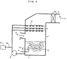
- FIG. 4 and FIG. 5 An example of a flue-gas desulfurization system of a conventional art is shown in FIG. 4 and FIG. 5 .
- the flue-gas desulfurization system is constructed mainly with an absorber shell 1, a gas inlet port 2, a gas outlet port 3, an absorbent liquid spray section 4, a spray nozzle 5, a recirculation pump 6, a recirculation tank section 7, an oxidation agitator 8, a posterior air pipe 10, a propeller 11, a gypsum slurry bleed pipe 20, a gypsum dewatering system 21, and a mist eliminator section 30.
- a flue gas G from a boiler is introduced through the gas inlet port 2 and makes gas-liquid contact with an absorbent liquid sprayed from the spray nozzle 5 of the absorbent liquid spray section 4 to thereby become a clean gas, and is emitted through the gas outlet port 3 after accompanying mist is removed therefrom by the mist eliminator section 30.
- the absorbent liquid brought in gas-liquid contact falls in the absorber shell 1 and is stored into the recirculation tank section 7.
- air 9 to be fed is atomized into a large amount of fine bubbles by the propeller 11 that rotates in conjunction with the oxidation agitator 8, and oxygen in the air dissolves in the absorbent liquid.
- calcium sulfite is produced by a neutralization reaction between absorbed SO 2 and calcium carbonate that is fed to the recirculation tank section 7 by an unillustrated calcium carbonate feeding system, and the calcium sulfite is oxidized by oxygen dissolved in the absorbent liquid to produce gypsum.
- the absorbent liquid in the recirculation tank section 7 where gypsum exists as slurry is sent again to the spray nozzle 5 by the recirculation pump 6, is partly sent to the gypsum dewatering system 21 through the gypsum slurry bleed pipe 20, and is therein separated into solid gypsum and water.
- the oxidation air 9 is fed from the posterior air pipe 10 with a feed port, which is at the rear of the propeller 11 of the agitator 8, to the recirculation tank section 7 as shown in FIG. 5 .
- This is a mode of increasing the air utilization rate by atomizing, by a shearing force generated by a rotation of the propeller 11, the oxidation air 9 fed to the recirculation tank section 7 into a large amount of fine bubbles to thereby increase a gas-liquid contact area with the absorbent liquid (Japanese Published Unexamined Patent Application No. 2001-120946 ).
- US 4239515 (A ) describes an apparatus for gas-liquid contact and separation by precipitation of solids therein, which essentially comprises a splash separating section, a solid-gas-liquid contact section and a solid depositing section formed in a single reaction vessel, in which gas is blown into the vessel through a gas disperser having a gas outlet opened below the liquid surface in said solid-gas-liquid contact section and caused to undergo contact with the phase of a suspension forcibly circulated from said solid depositing section formed below said solid-gas-liquid contact section, whereby the precipitated solids are prevented from depositing the inner surface of the vessel and other attendant members.
- US 5429808 (A ) describes an apparatus for wet process exhaust gas desulfurization including a spraying portion for spreading absorbent slurry, a plurality of stirrers for stirring each stirrer being an axial flow type agitator having a propeller, and a circular system for circulating the absorbent slurry from the slurry tank to the spraying portion.
- the apparatus further includes a plurality of nozzles for feeding oxidizer gas into the absorbent slurry from a backside of each propeller towards a periphery thereof uniformly with respect to a circumferential direction.
- the mode of feeding the oxidation air 9 from the posterior air pipe 10 with a feed port at the rear of the propeller 11 of the agitator 8 to the recirculation tank section 7 shown in FIG. 5 may not sufficiently cope with a case where a flue gas with a high SO 2 concentration is treated due to diversification of boiler fuels and the like in recent years. More specifically, when a flue gas with a high SO 2 concentration is treated, the amount of calcium sulfite (Ca (HSO 3 ) 2 ) in the absorbent liquid increases, and therewith the amount of oxidation air to be fed also increases.
- Ca (HSO 3 ) 2 calcium sulfite
- the mode of feeding air into the absorbent liquid at the front of the agitator propeller 11 allows uniformly dispersing oxidation air bubbles in the recirculation tank section 7 while atomizing the same to fine bubbles, however, since the air itself to be fed to the front of the propeller 11 does not contact the rotating propeller 11, the size of fine air bubbles is larger than that by the method for feeding air to the rear of the propeller 11, and thus the contact area with the absorbent liquid is reduced, so that the oxidation efficiency is lowered.
- the amount of SO 2 that should be removed has tended to increase in a flue gas, and therewith the amount of oxidation air has also increased.
- the amount of oxidation air that can be fed per one agitator 8 the amount of a discharge flow resulting from a rotation of the propeller 11 is reduced when air of an amount larger than the limit is fed, which results in a state of the propeller 11 idly rotating in the fed air 9, so that air bubbles 12 are not atomized to fine bubbles, the gas-liquid contact area between the oxidation air bubbles 12 and the absorbent liquid is reduced, and the oxidation efficiency of SO 2 is lowered.
- the agitator 8 often performs, simultaneously with atomization of the oxidation air 9, agitation for preventing settlement of solids in an absorbent liquid slurry in the recirculation tank section 7, and if the amount of a discharge flow from the propeller 11 is reduced by an increase in the amount of oxidation air, solids in the absorbent liquid slurry also settle at the bottom of the recirculation tank section 7, and this causes an inconvenience in operation of the plant, such as clogging of the pipes.
- a first aspect of the invention provides a wet flue-gas desulfurization system including: an absorber shell including a flue gas inlet port through which a flue gas containing a sulfur oxide and soot and dust emitted from a combustion system such as a boiler is introduced and an absorbent liquid spray section provided at a higher portion than the flue gas inlet port; and a recirculation tank section which stores an absorbent liquid that has absorbed a sulfur oxide in a flue gas and includes an agitator including a propeller to agitate the absorbent liquid, an air feeding means which injects oxidation air into a vicinity of the propeller, and an absorbent liquid circulating means which extracts the absorbent liquid from the recirculation tank after an oxidation reaction by air and a neutralization reaction by alkali and circulatively feeds the absorbent liquid to the absorbent liquid spray section of the absorber shell, wherein the air feeding means is a means for feeding oxidation air to the absorbent liquid in the recirculation tank section at the
- the front of a liquid discharge by the propeller denotes a direction in which the absorbent liquid in the recirculation tank section is discharged by a propeller for which the direction of a liquid discharge has been previously determined
- the rear of a liquid discharge by the propeller denotes a direction opposite the direction in which the absorbent liquid is discharged.
- a second aspect of the invention provides the wet flue-gas desulfurization system according to the first aspect, wherein an air injection port of the air feeding means to be installed at the front of a liquid discharge by the propeller of the agitator is arranged at a position lower than an extended line of a horizontal central axis of the propeller.
- a third aspect of the invention provides a method for wet flue-gas desulfurization in which a ratio of the amount of air to be fed, by use of the wet flue-gas desulfurization system according to the first or second aspects, to the rear and front of a liquid discharge by the propeller of the agitator, from the air feeding means that feeds oxidation air to the absorbent liquid in the recirculation tank section at the rear and front of a liquid discharge by the propeller of the agitator, is higher at the front of a liquid discharge than at the rear of a liquid discharge.
- a fourth aspect of the invention provides the method for wet flue-gas desulfurization according to the third aspect, wherein, of a required amount of air, a ratio of the amount of air to be fed to the rear and front of a liquid discharge by the propeller of the agitator is 10% at the rear of a liquid discharge and 90% at the front of a liquid discharge.
- a fifth aspect of the invention provides the method for wet flue-gas desulfurization according to the third aspect, wherein when the oxidation air to be fed to the air feeding means is changed in amount, of a required amount of air, an amount of air to be fed to the rear of a liquid discharge by the propeller of the agitator is kept constant, and an amount of air to be fed to the front of a liquid discharge by the propeller of the agitator is changed.
- Japanese Unexamined Patent Application No. H05-317642 and Japanese Unexamined Patent Application No. S59-13624 of the conventional arts disclosed is a mode of feeding oxidation air into an absorbent liquid of a recirculation tank section, across the front and rear in a liquid discharge direction of an agitator propeller, from above and below thereof.
- the air bubbles can be atomized to fine bubbles and the air bubbles can be uniformly dispersed in the recirculation tank section even when the amount of oxidation air is increased, it is possible to improve oxidation efficiency without increasing the number of agitators installed, and by adjusting the ratio of the amount of air to be fed to the rear and front of the propeller makes it possible to cope with a change in boiler load.
- a lower side of the propeller is faster in discharge flow speed and more easily forms a flow up to almost the center of the recirculation tank section, and thus the air bubbles are easily dispersed in the absorbent liquid of the recirculation tank section and the retention time is increased, and therefore, oxidation efficiency of SO 2 in the absorbent liquid is improved.
- both effects of atomizing air to fine bubbles to be fed from the front of the propeller and an increase in the retention time improve oxidation efficiency of SO 2 in the absorbent liquid.
- air to be fed from the rear of the propeller of the agitator is atomized to fine bubbles by a shearing force resulting from a rotation of the propeller, and since this air is constant, there is an effect that a constant air bubble dispersion distance and retention time in the recirculation tank section can be maintained also for air to be fed to the front of the propeller.
- FIG. 1 is a sectional side view of a wet flue-gas desulfurization system according to a concrete example of the present invention.
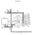
- FIG. 2 is an enlarged sectional view of a recirculation tank section of the wet flue-gas desulfurization system in FIG. 1 .
- FIG. 1 and FIG. 2 are sectional side views of a wet flue-gas desulfurization systems according to a concrete example of the present invention.
- FIG. 2 is an enlarged sectional view of a recirculation tank section of the wet flue-gas desulfurization system in FIG. 1 .
- the flue-gas desulfurization system is constructed mainly with an absorber shell 1, a gas inlet port 2, a gas outlet port 3, an absorbent liquid spray section 4, a spray nozzle 5, a recirculation pump 6, a recirculation tank section 7, an oxidation agitator 8, a posterior air pipe 10, a propeller 11, an anterior air pipe 13, a gypsum slurry bleed pipe 20, a gypsum dewatering system 21, and a mist eliminator section 30.
- a flue gas G of a boiler is introduced through the gas inlet port 2 and makes gas-liquid contact with an absorbent liquid sprayed from the spray nozzle 5 of the absorbent liquid spray section 4 to thereby become a clean gas, and is emitted through the gas outlet port 3 after accompanying mist is removed therefrom by the mist eliminator section 30. Moreover, the absorbent liquid brought in gas-liquid contact falls in the absorber shell 1 and is stored into the recirculation tank section 7.
- the absorbent liquid in the recirculation tank section 7 where gypsum exists as slurry is sent again to the spray nozzle 5 by the recirculation pump 6, is partly sent to the gypsum dewatering system 21 through the gypsum slurry bleed pipe 20, and is therein separated into solid gypsum and water.
- the posterior air pipe 10 can be arranged at a position which allows feeding air 9 within the range of a blade diameter of the propeller 11, while an outlet of the anterior air pipe 13 is preferably arranged at a position which allows feeding air 9 to a position slightly lower than being on a horizontal extended line of a central axis of rotation of the propeller 11 within the range of a blade diameter of the propeller 11.
- a constant amount of air is basically fed irrespective of a change in load of the boiler, while when the amount of air is changed with a change in boiler load, by changing the amount of air to be fed from the anterior air pipe 13 according to the boiler load while keeping the amount of air to be fed from the posterior air pipe 10 constant, the air 9 to be fed from the rear of a liquid discharge by the propeller 11 of the agitator 8 is atomized to fine bubbles by a shearing force resulting from a rotation of the propeller 11, and since this air 9 is constant, there is an effect that a constant air bubble dispersion distance and retention time in the recirculation tank section 7 can be maintained also for the air 9 to be fed to the front of a liquid discharge by the propeller 11.
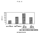
- Fig. 3 is a chart of comparison in the ORP (oxidation-reduction potential) value in an absorbent liquid, in terms of oxidation of calcium sulfate in flue-gas desulfurization systems with specifications shown in Table 1 that treat the same amount of SO 2 to be removed and control an airflow in each of the air pipes 10 and 13, between when the oxidation air 9 was fed from the rear of a liquid discharge by the propeller 11 and when being fed from the front of a liquid discharge by the propeller 11 in a conventional art and when being fed from the rear of a liquid discharge by the propeller 11 and when being fed from the front of a liquid discharge by the propeller 11 in the present invention.
- ORP oxidation-reduction potential
- ORP indicates an oxidation state of the absorbent liquid, and the higher the ORP value, the higher oxidation efficiency of calcium sulfite becomes.
- [Table 1] Amount of treated flue gas 600, 000 m 3 N/h Inlet SO 2 concentration 760 ppm Number of oxidizing agitators 3 Oxidation air feeding position Front and rear of propeller (Installation of air pipes at front and rear)
- the ratio of the amount of air to be fed to the rear and front of the propeller 11 is desirably made higher at the front than at the rear in the feeding ratio.
- the present invention has high industrial applicability as a wet flue-gas desulfurization system and method with which even when the amount of oxidation air to be fed to the recirculation tank section is increased, highly efficient oxidation can be performed without increasing the number of agitators installed and the operating cost.
Landscapes
- Engineering & Computer Science (AREA)
- Chemical & Material Sciences (AREA)
- Health & Medical Sciences (AREA)
- Biomedical Technology (AREA)
- Environmental & Geological Engineering (AREA)
- Analytical Chemistry (AREA)
- General Chemical & Material Sciences (AREA)
- Oil, Petroleum & Natural Gas (AREA)
- Chemical Kinetics & Catalysis (AREA)
- Treating Waste Gases (AREA)
- Gas Separation By Absorption (AREA)
Priority Applications (1)
| Application Number | Priority Date | Filing Date | Title |
|---|---|---|---|
| PL06810295T PL1958682T3 (pl) | 2005-12-07 | 2006-09-20 | Urządzenie do mokrego odsiarczania gazów odlotowych i sposób mokrego odsiarczania gazów odlotowych |
Applications Claiming Priority (2)
| Application Number | Priority Date | Filing Date | Title |
|---|---|---|---|
| JP2005353164 | 2005-12-07 | ||
| PCT/JP2006/318595 WO2007066443A1 (ja) | 2005-12-07 | 2006-09-20 | 湿式排煙脱硫装置と湿式排煙脱硫方法 |
Publications (3)
| Publication Number | Publication Date |
|---|---|
| EP1958682A1 EP1958682A1 (en) | 2008-08-20 |
| EP1958682A4 EP1958682A4 (en) | 2010-03-24 |
| EP1958682B1 true EP1958682B1 (en) | 2011-04-13 |
Family
ID=38122595
Family Applications (1)
| Application Number | Title | Priority Date | Filing Date |
|---|---|---|---|
| EP06810295A Not-in-force EP1958682B1 (en) | 2005-12-07 | 2006-09-20 | Wet flue-gas desulfurization apparatus and method of wet flue-gas desulfurization |
Country Status (9)
| Country | Link |
|---|---|
| US (1) | US7731926B2 (pl) |
| EP (1) | EP1958682B1 (pl) |
| JP (1) | JP4776630B2 (pl) |
| AU (1) | AU2006322822B2 (pl) |
| CA (1) | CA2629766A1 (pl) |
| DE (1) | DE602006021341D1 (pl) |
| ES (1) | ES2360558T3 (pl) |
| PL (1) | PL1958682T3 (pl) |
| WO (1) | WO2007066443A1 (pl) |
Cited By (1)
| Publication number | Priority date | Publication date | Assignee | Title |
|---|---|---|---|---|
| CN102658018A (zh) * | 2012-05-11 | 2012-09-12 | 济南大学 | 旋网脱硫除尘装置 |
Families Citing this family (20)
| Publication number | Priority date | Publication date | Assignee | Title |
|---|---|---|---|---|
| CN101511446B (zh) * | 2006-07-26 | 2012-05-02 | 巴布考克日立株式会社 | 排气中微量有害物质的除去装置和其运行方法 |
| JP5046755B2 (ja) * | 2007-06-27 | 2012-10-10 | 三菱重工業株式会社 | 気液接触装置 |
| CN101670228B (zh) * | 2009-09-25 | 2011-07-27 | 东南大学 | 浆液池搅拌氧化装置 |
| CN101816884A (zh) * | 2010-04-22 | 2010-09-01 | 张保金 | 一种烟囱烟气除硫、除尘的降温处理方法及设备 |
| CN102091520B (zh) * | 2010-12-28 | 2012-08-22 | 哈尔滨工业大学 | 基于湿法脱硫装置的循环浆液降尘处理方法及湿法脱硫装置 |
| ES2392280B2 (es) | 2011-05-10 | 2013-06-10 | Universidad De Sevilla | Procedimiento de captura de co2 y so2. |
| CN103055689B (zh) * | 2013-01-09 | 2015-06-17 | 浙江大学 | 一种同时稳定二价汞的脱硫吸收液 |
| CN103480263A (zh) * | 2013-10-17 | 2014-01-01 | 江苏欧超环保科技有限公司 | 一种预荷电喷淋脱硫除尘装置 |
| CN104667719A (zh) * | 2013-11-26 | 2015-06-03 | 上海交通大学 | 烟气逆流直排式净化方法 |
| US10375901B2 (en) | 2014-12-09 | 2019-08-13 | Mtd Products Inc | Blower/vacuum |
| KR102048538B1 (ko) * | 2018-01-25 | 2019-11-25 | 두산중공업 주식회사 | 습식배연 탈황장치 |
| KR102048539B1 (ko) * | 2018-01-19 | 2019-11-25 | 두산중공업 주식회사 | 습식배연 탈황장치 |
| US11065576B2 (en) | 2018-01-19 | 2021-07-20 | Doosan Heavy Industries & Construction Co., Ltd. | Wet flue gas desulfurization apparatus |
| CN110559816B (zh) * | 2018-06-05 | 2021-10-08 | 中国石油化工股份有限公司 | 烟气脱硫塔和烟气除尘、脱硫及废水处理工艺 |
| CN108905561A (zh) * | 2018-06-20 | 2018-11-30 | 西昌宏鑫实业有限公司 | 一种吸收锅炉尾气中so2和粉尘烟气治理装置及方法 |
| CN112692026B (zh) * | 2021-01-05 | 2023-06-13 | 江西依露得力医疗科技有限公司 | 一种麻醉科室用废气吸收处理装置 |
| CN112958289A (zh) * | 2021-02-05 | 2021-06-15 | 北京中科润宇环保科技股份有限公司 | 湿法脱硫硫磺浮选的装置及方法 |
| CN112791569A (zh) * | 2021-03-09 | 2021-05-14 | 昆明理工大学 | 电化学协同微乳液净化酸性气体的方法 |
| CN114307573A (zh) * | 2021-12-16 | 2022-04-12 | 徐州工业锅炉有限公司 | 一种火力发电锅炉内烟气排放处理装置 |
| CN115888308B (zh) * | 2023-01-07 | 2025-12-23 | 东莞市华志光电科技有限公司 | 一种水混合烟雾气体杂质净化分离系统 |
Family Cites Families (8)
| Publication number | Priority date | Publication date | Assignee | Title |
|---|---|---|---|---|
| JPS5915688B2 (ja) * | 1976-08-10 | 1984-04-11 | 千代田化工建設株式会社 | 気液接触装置 |
| JPS5913624A (ja) | 1982-07-14 | 1984-01-24 | ゼネラル・エレクトリツク・カンパニイ | 1基の排煙脱硫装置内で同時に石膏を副生する方法 |
| JP2774519B2 (ja) * | 1988-09-06 | 1998-07-09 | バブコツク日立株式会社 | 湿式排ガス脱硫装置 |
| JPH05317642A (ja) | 1992-05-14 | 1993-12-03 | Ishikawajima Harima Heavy Ind Co Ltd | 湿式排煙脱硫装置の吸収塔 |
| JP3381389B2 (ja) | 1994-06-17 | 2003-02-24 | 石川島播磨重工業株式会社 | 気体吹込装置 |
| JP3573950B2 (ja) * | 1997-06-24 | 2004-10-06 | 東洋エンジニアリング株式会社 | 排ガスの脱硫方法 |
| JP2000317259A (ja) | 1999-05-11 | 2000-11-21 | Ishikawajima Harima Heavy Ind Co Ltd | 排煙脱硫装置 |
| JP2001120946A (ja) | 1999-10-21 | 2001-05-08 | Babcock Hitachi Kk | 湿式排煙脱硫装置とその運転方法 |
-
2006
- 2006-09-20 PL PL06810295T patent/PL1958682T3/pl unknown
- 2006-09-20 AU AU2006322822A patent/AU2006322822B2/en not_active Ceased
- 2006-09-20 JP JP2007549025A patent/JP4776630B2/ja not_active Expired - Fee Related
- 2006-09-20 CA CA002629766A patent/CA2629766A1/en not_active Abandoned
- 2006-09-20 DE DE602006021341T patent/DE602006021341D1/de active Active
- 2006-09-20 ES ES06810295T patent/ES2360558T3/es active Active
- 2006-09-20 US US12/092,787 patent/US7731926B2/en active Active
- 2006-09-20 EP EP06810295A patent/EP1958682B1/en not_active Not-in-force
- 2006-09-20 WO PCT/JP2006/318595 patent/WO2007066443A1/ja not_active Ceased
Cited By (2)
| Publication number | Priority date | Publication date | Assignee | Title |
|---|---|---|---|---|
| CN102658018A (zh) * | 2012-05-11 | 2012-09-12 | 济南大学 | 旋网脱硫除尘装置 |
| CN102658018B (zh) * | 2012-05-11 | 2014-03-12 | 济南大学 | 旋网脱硫除尘装置 |
Also Published As
| Publication number | Publication date |
|---|---|
| JP4776630B2 (ja) | 2011-09-21 |
| CA2629766A1 (en) | 2007-06-14 |
| AU2006322822A1 (en) | 2007-06-14 |
| PL1958682T3 (pl) | 2011-07-29 |
| US20090263305A1 (en) | 2009-10-22 |
| WO2007066443A1 (ja) | 2007-06-14 |
| US7731926B2 (en) | 2010-06-08 |
| JPWO2007066443A1 (ja) | 2009-05-14 |
| EP1958682A4 (en) | 2010-03-24 |
| EP1958682A1 (en) | 2008-08-20 |
| AU2006322822B2 (en) | 2010-07-15 |
| ES2360558T3 (es) | 2011-06-07 |
| DE602006021341D1 (de) | 2011-05-26 |
Similar Documents
| Publication | Publication Date | Title |
|---|---|---|
| EP1958682B1 (en) | Wet flue-gas desulfurization apparatus and method of wet flue-gas desulfurization | |
| CN1083290C (zh) | 采用固体脱硫剂的湿式烟道气脱硫设备和方法 | |
| EP1243308B1 (en) | Apparatus for wet type flue-gas desulfurization | |
| CN108636092B (zh) | 一种烟气脱硫脱硝系统及方法 | |
| CN105169926B (zh) | 一种烟气脱硫系统及利用其进行烟气脱硫的方法 | |
| US11065576B2 (en) | Wet flue gas desulfurization apparatus | |
| KR100285102B1 (ko) | 습식 연도 가스 탈황장치 및 연도 가스 탈황장치의 산소 함유가스 송풍장치 | |
| CN105233659B (zh) | 一种烟气脱硫塔及烟气脱硫方法 | |
| CN206881495U (zh) | 脱除烟气中二氧化硫和汞的装置 | |
| CN208553730U (zh) | 一种烟气脱硫脱硝系统 | |
| JP3392635B2 (ja) | 排煙処理方法及び装置 | |
| CN217410334U (zh) | 一种炭素煅烧炉烟气处理系统 | |
| JP3910307B2 (ja) | 湿式排煙脱硫装置 | |
| CN211098394U (zh) | 一种控制喷淋浆液ph值的湿法脱硫系统 | |
| CN210448716U (zh) | 一种高效烟气气动乳化除尘、脱硫装置 | |
| JP3068452B2 (ja) | 湿式排煙脱硫装置 | |
| KR20210079839A (ko) | 탈황설비용 펌프의 임펠러 | |
| CN1266046C (zh) | 烟气脱硫中间产物-亚硫酸钙的强制氧化方法及其装置 | |
| JPH08215532A (ja) | ガス吸収装置 | |
| KR0135324B1 (ko) | 배연탈황 공정의 공기공급 교반장치 | |
| CN113274870A (zh) | 一种炭素煅烧炉烟气处理方法及其系统 | |
| JPH02111420A (ja) | 湿式排煙脱硫装置 | |
| CN118142321A (zh) | 一种烟气脱硫塔和烟气脱硫工艺 | |
| JPH0686912A (ja) | 湿式排煙脱硫装置 | |
| JPS63158119A (ja) | 湿式排煙脱硫装置 |
Legal Events
| Date | Code | Title | Description |
|---|---|---|---|
| PUAI | Public reference made under article 153(3) epc to a published international application that has entered the european phase |
Free format text: ORIGINAL CODE: 0009012 |
|
| 17P | Request for examination filed |
Effective date: 20080514 |
|
| AK | Designated contracting states |
Kind code of ref document: A1 Designated state(s): AT BE BG CH CY CZ DE DK EE ES FI FR GB GR HU IE IS IT LI LT LU LV MC NL PL PT RO SE SI SK TR |
|
| A4 | Supplementary search report drawn up and despatched |
Effective date: 20100224 |
|
| 17Q | First examination report despatched |
Effective date: 20100526 |
|
| RIC1 | Information provided on ipc code assigned before grant |
Ipc: B01D 53/77 20060101ALI20100721BHEP Ipc: B01D 53/50 20060101AFI20100721BHEP Ipc: B01D 53/18 20060101ALI20100721BHEP |
|
| GRAP | Despatch of communication of intention to grant a patent |
Free format text: ORIGINAL CODE: EPIDOSNIGR1 |
|
| DAX | Request for extension of the european patent (deleted) | ||
| GRAS | Grant fee paid |
Free format text: ORIGINAL CODE: EPIDOSNIGR3 |
|
| GRAA | (expected) grant |
Free format text: ORIGINAL CODE: 0009210 |
|
| AK | Designated contracting states |
Kind code of ref document: B1 Designated state(s): AT BE BG CH CY CZ DE DK EE ES FI FR GB GR HU IE IS IT LI LT LU LV MC NL PL PT RO SE SI SK TR |
|
| REG | Reference to a national code |
Ref country code: GB Ref legal event code: FG4D |
|
| REG | Reference to a national code |
Ref country code: CH Ref legal event code: EP |
|
| REG | Reference to a national code |
Ref country code: IE Ref legal event code: FG4D |
|
| REF | Corresponds to: |
Ref document number: 602006021341 Country of ref document: DE Date of ref document: 20110526 Kind code of ref document: P |
|
| REG | Reference to a national code |
Ref country code: DE Ref legal event code: R096 Ref document number: 602006021341 Country of ref document: DE Effective date: 20110526 |
|
| REG | Reference to a national code |
Ref country code: ES Ref legal event code: FG2A Ref document number: 2360558 Country of ref document: ES Kind code of ref document: T3 Effective date: 20110607 |
|
| REG | Reference to a national code |
Ref country code: NL Ref legal event code: VDEP Effective date: 20110413 |
|
| REG | Reference to a national code |
Ref country code: PL Ref legal event code: T3 |
|
| LTIE | Lt: invalidation of european patent or patent extension |
Effective date: 20110413 |
|
| PG25 | Lapsed in a contracting state [announced via postgrant information from national office to epo] |
Ref country code: SE Free format text: LAPSE BECAUSE OF FAILURE TO SUBMIT A TRANSLATION OF THE DESCRIPTION OR TO PAY THE FEE WITHIN THE PRESCRIBED TIME-LIMIT Effective date: 20110413 Ref country code: PT Free format text: LAPSE BECAUSE OF FAILURE TO SUBMIT A TRANSLATION OF THE DESCRIPTION OR TO PAY THE FEE WITHIN THE PRESCRIBED TIME-LIMIT Effective date: 20110816 Ref country code: LT Free format text: LAPSE BECAUSE OF FAILURE TO SUBMIT A TRANSLATION OF THE DESCRIPTION OR TO PAY THE FEE WITHIN THE PRESCRIBED TIME-LIMIT Effective date: 20110413 |
|
| PG25 | Lapsed in a contracting state [announced via postgrant information from national office to epo] |
Ref country code: BE Free format text: LAPSE BECAUSE OF FAILURE TO SUBMIT A TRANSLATION OF THE DESCRIPTION OR TO PAY THE FEE WITHIN THE PRESCRIBED TIME-LIMIT Effective date: 20110413 Ref country code: LV Free format text: LAPSE BECAUSE OF FAILURE TO SUBMIT A TRANSLATION OF THE DESCRIPTION OR TO PAY THE FEE WITHIN THE PRESCRIBED TIME-LIMIT Effective date: 20110413 Ref country code: CY Free format text: LAPSE BECAUSE OF FAILURE TO SUBMIT A TRANSLATION OF THE DESCRIPTION OR TO PAY THE FEE WITHIN THE PRESCRIBED TIME-LIMIT Effective date: 20110413 Ref country code: GR Free format text: LAPSE BECAUSE OF FAILURE TO SUBMIT A TRANSLATION OF THE DESCRIPTION OR TO PAY THE FEE WITHIN THE PRESCRIBED TIME-LIMIT Effective date: 20110714 Ref country code: FI Free format text: LAPSE BECAUSE OF FAILURE TO SUBMIT A TRANSLATION OF THE DESCRIPTION OR TO PAY THE FEE WITHIN THE PRESCRIBED TIME-LIMIT Effective date: 20110413 Ref country code: SI Free format text: LAPSE BECAUSE OF FAILURE TO SUBMIT A TRANSLATION OF THE DESCRIPTION OR TO PAY THE FEE WITHIN THE PRESCRIBED TIME-LIMIT Effective date: 20110413 Ref country code: AT Free format text: LAPSE BECAUSE OF FAILURE TO SUBMIT A TRANSLATION OF THE DESCRIPTION OR TO PAY THE FEE WITHIN THE PRESCRIBED TIME-LIMIT Effective date: 20110413 Ref country code: IS Free format text: LAPSE BECAUSE OF FAILURE TO SUBMIT A TRANSLATION OF THE DESCRIPTION OR TO PAY THE FEE WITHIN THE PRESCRIBED TIME-LIMIT Effective date: 20110813 |
|
| PG25 | Lapsed in a contracting state [announced via postgrant information from national office to epo] |
Ref country code: NL Free format text: LAPSE BECAUSE OF FAILURE TO SUBMIT A TRANSLATION OF THE DESCRIPTION OR TO PAY THE FEE WITHIN THE PRESCRIBED TIME-LIMIT Effective date: 20110413 |
|
| PG25 | Lapsed in a contracting state [announced via postgrant information from national office to epo] |
Ref country code: EE Free format text: LAPSE BECAUSE OF FAILURE TO SUBMIT A TRANSLATION OF THE DESCRIPTION OR TO PAY THE FEE WITHIN THE PRESCRIBED TIME-LIMIT Effective date: 20110413 |
|
| PLBE | No opposition filed within time limit |
Free format text: ORIGINAL CODE: 0009261 |
|
| STAA | Information on the status of an ep patent application or granted ep patent |
Free format text: STATUS: NO OPPOSITION FILED WITHIN TIME LIMIT |
|
| PG25 | Lapsed in a contracting state [announced via postgrant information from national office to epo] |
Ref country code: RO Free format text: LAPSE BECAUSE OF FAILURE TO SUBMIT A TRANSLATION OF THE DESCRIPTION OR TO PAY THE FEE WITHIN THE PRESCRIBED TIME-LIMIT Effective date: 20110413 Ref country code: SK Free format text: LAPSE BECAUSE OF FAILURE TO SUBMIT A TRANSLATION OF THE DESCRIPTION OR TO PAY THE FEE WITHIN THE PRESCRIBED TIME-LIMIT Effective date: 20110413 Ref country code: DK Free format text: LAPSE BECAUSE OF FAILURE TO SUBMIT A TRANSLATION OF THE DESCRIPTION OR TO PAY THE FEE WITHIN THE PRESCRIBED TIME-LIMIT Effective date: 20110413 |
|
| 26N | No opposition filed |
Effective date: 20120116 |
|
| PG25 | Lapsed in a contracting state [announced via postgrant information from national office to epo] |
Ref country code: MC Free format text: LAPSE BECAUSE OF NON-PAYMENT OF DUE FEES Effective date: 20110930 |
|
| REG | Reference to a national code |
Ref country code: CH Ref legal event code: PL |
|
| REG | Reference to a national code |
Ref country code: DE Ref legal event code: R097 Ref document number: 602006021341 Country of ref document: DE Effective date: 20120116 |
|
| GBPC | Gb: european patent ceased through non-payment of renewal fee |
Effective date: 20110920 |
|
| PG25 | Lapsed in a contracting state [announced via postgrant information from national office to epo] |
Ref country code: IT Free format text: LAPSE BECAUSE OF FAILURE TO SUBMIT A TRANSLATION OF THE DESCRIPTION OR TO PAY THE FEE WITHIN THE PRESCRIBED TIME-LIMIT Effective date: 20110413 |
|
| REG | Reference to a national code |
Ref country code: IE Ref legal event code: MM4A |
|
| REG | Reference to a national code |
Ref country code: FR Ref legal event code: ST Effective date: 20120531 |
|
| PG25 | Lapsed in a contracting state [announced via postgrant information from national office to epo] |
Ref country code: IE Free format text: LAPSE BECAUSE OF NON-PAYMENT OF DUE FEES Effective date: 20110920 Ref country code: CH Free format text: LAPSE BECAUSE OF NON-PAYMENT OF DUE FEES Effective date: 20110930 Ref country code: LI Free format text: LAPSE BECAUSE OF NON-PAYMENT OF DUE FEES Effective date: 20110930 |
|
| PG25 | Lapsed in a contracting state [announced via postgrant information from national office to epo] |
Ref country code: GB Free format text: LAPSE BECAUSE OF NON-PAYMENT OF DUE FEES Effective date: 20110920 Ref country code: FR Free format text: LAPSE BECAUSE OF NON-PAYMENT OF DUE FEES Effective date: 20110930 |
|
| PG25 | Lapsed in a contracting state [announced via postgrant information from national office to epo] |
Ref country code: LU Free format text: LAPSE BECAUSE OF NON-PAYMENT OF DUE FEES Effective date: 20110920 |
|
| PG25 | Lapsed in a contracting state [announced via postgrant information from national office to epo] |
Ref country code: BG Free format text: LAPSE BECAUSE OF FAILURE TO SUBMIT A TRANSLATION OF THE DESCRIPTION OR TO PAY THE FEE WITHIN THE PRESCRIBED TIME-LIMIT Effective date: 20110713 |
|
| PG25 | Lapsed in a contracting state [announced via postgrant information from national office to epo] |
Ref country code: TR Free format text: LAPSE BECAUSE OF FAILURE TO SUBMIT A TRANSLATION OF THE DESCRIPTION OR TO PAY THE FEE WITHIN THE PRESCRIBED TIME-LIMIT Effective date: 20110413 |
|
| PG25 | Lapsed in a contracting state [announced via postgrant information from national office to epo] |
Ref country code: HU Free format text: LAPSE BECAUSE OF FAILURE TO SUBMIT A TRANSLATION OF THE DESCRIPTION OR TO PAY THE FEE WITHIN THE PRESCRIBED TIME-LIMIT Effective date: 20110413 |
|
| REG | Reference to a national code |
Ref country code: DE Ref legal event code: R082 Ref document number: 602006021341 Country of ref document: DE Representative=s name: TBK, DE |
|
| REG | Reference to a national code |
Ref country code: DE Ref legal event code: R081 Ref document number: 602006021341 Country of ref document: DE Owner name: MITSUBISHI HITACHI POWER SYSTEMS, LTD., YOKOHA, JP Free format text: FORMER OWNER: BABCOCK-HITACHI K.K., TOKIO/TOKYO, JP Effective date: 20150305 Ref country code: DE Ref legal event code: R082 Ref document number: 602006021341 Country of ref document: DE Representative=s name: TBK, DE Effective date: 20150305 |
|
| REG | Reference to a national code |
Ref country code: ES Ref legal event code: PC2A Owner name: MITSUBISHI HITACHI POWER SYSTEMS, LTD. Effective date: 20150421 |
|
| REG | Reference to a national code |
Ref country code: DE Ref legal event code: R082 Ref document number: 602006021341 Country of ref document: DE Representative=s name: TBK, DE Ref country code: DE Ref legal event code: R081 Ref document number: 602006021341 Country of ref document: DE Owner name: MITSUBISHI POWER, LTD., JP Free format text: FORMER OWNER: MITSUBISHI HITACHI POWER SYSTEMS, LTD., YOKOHAMA, KANAGAWA, JP |
|
| REG | Reference to a national code |
Ref country code: ES Ref legal event code: PC2A Owner name: MITSUBISHI POWER, LTD. Effective date: 20210421 |
|
| PGFP | Annual fee paid to national office [announced via postgrant information from national office to epo] |
Ref country code: CZ Payment date: 20210826 Year of fee payment: 16 |
|
| PGFP | Annual fee paid to national office [announced via postgrant information from national office to epo] |
Ref country code: PL Payment date: 20210813 Year of fee payment: 16 Ref country code: DE Payment date: 20210810 Year of fee payment: 16 |
|
| PGFP | Annual fee paid to national office [announced via postgrant information from national office to epo] |
Ref country code: ES Payment date: 20211001 Year of fee payment: 16 |
|
| REG | Reference to a national code |
Ref country code: DE Ref legal event code: R119 Ref document number: 602006021341 Country of ref document: DE |
|
| PG25 | Lapsed in a contracting state [announced via postgrant information from national office to epo] |
Ref country code: CZ Free format text: LAPSE BECAUSE OF NON-PAYMENT OF DUE FEES Effective date: 20220920 |
|
| PG25 | Lapsed in a contracting state [announced via postgrant information from national office to epo] |
Ref country code: DE Free format text: LAPSE BECAUSE OF NON-PAYMENT OF DUE FEES Effective date: 20230401 |
|
| REG | Reference to a national code |
Ref country code: ES Ref legal event code: FD2A Effective date: 20231027 |
|
| PG25 | Lapsed in a contracting state [announced via postgrant information from national office to epo] |
Ref country code: ES Free format text: LAPSE BECAUSE OF NON-PAYMENT OF DUE FEES Effective date: 20220921 |
|
| PG25 | Lapsed in a contracting state [announced via postgrant information from national office to epo] |
Ref country code: ES Free format text: LAPSE BECAUSE OF NON-PAYMENT OF DUE FEES Effective date: 20220921 |
|
| PG25 | Lapsed in a contracting state [announced via postgrant information from national office to epo] |
Ref country code: PL Free format text: LAPSE BECAUSE OF NON-PAYMENT OF DUE FEES Effective date: 20220920 |