EP1958231B1 - Korrektiv zur beseitigung des öffnungsfehlers 3. ordnung und des axialen farbfehlers 1. ordnung 1. grades - Google Patents
Korrektiv zur beseitigung des öffnungsfehlers 3. ordnung und des axialen farbfehlers 1. ordnung 1. grades Download PDFInfo
- Publication number
- EP1958231B1 EP1958231B1 EP05816963.2A EP05816963A EP1958231B1 EP 1958231 B1 EP1958231 B1 EP 1958231B1 EP 05816963 A EP05816963 A EP 05816963A EP 1958231 B1 EP1958231 B1 EP 1958231B1
- Authority
- EP
- European Patent Office
- Prior art keywords
- corrective
- correction
- fields
- quadrupole
- field
- Prior art date
- Legal status (The legal status is an assumption and is not a legal conclusion. Google has not performed a legal analysis and makes no representation as to the accuracy of the status listed.)
- Active
Links
- 230000004075 alteration Effects 0.000 title claims description 36
- 238000012937 correction Methods 0.000 claims description 103
- 230000003287 optical effect Effects 0.000 claims description 29
- 230000005405 multipole Effects 0.000 claims description 23
- 238000003384 imaging method Methods 0.000 description 10
- 206010010071 Coma Diseases 0.000 description 9
- 201000009310 astigmatism Diseases 0.000 description 6
- 230000005540 biological transmission Effects 0.000 description 4
- 238000010276 construction Methods 0.000 description 3
- 238000001493 electron microscopy Methods 0.000 description 3
- 238000012634 optical imaging Methods 0.000 description 3
- 230000001133 acceleration Effects 0.000 description 2
- 230000008901 benefit Effects 0.000 description 2
- 230000008030 elimination Effects 0.000 description 2
- 238000003379 elimination reaction Methods 0.000 description 2
- 238000002173 high-resolution transmission electron microscopy Methods 0.000 description 2
- 230000007547 defect Effects 0.000 description 1
- 230000007812 deficiency Effects 0.000 description 1
- 230000001419 dependent effect Effects 0.000 description 1
- 238000010894 electron beam technology Methods 0.000 description 1
- 238000001239 high-resolution electron microscopy Methods 0.000 description 1
- 238000005286 illumination Methods 0.000 description 1
- 230000006872 improvement Effects 0.000 description 1
- 238000001459 lithography Methods 0.000 description 1
- 238000013507 mapping Methods 0.000 description 1
- 239000002245 particle Substances 0.000 description 1
- 230000009467 reduction Effects 0.000 description 1
- 238000007493 shaping process Methods 0.000 description 1
- 238000004627 transmission electron microscopy Methods 0.000 description 1
Images
Classifications
-
- H—ELECTRICITY
- H01—ELECTRIC ELEMENTS
- H01J—ELECTRIC DISCHARGE TUBES OR DISCHARGE LAMPS
- H01J37/00—Discharge tubes with provision for introducing objects or material to be exposed to the discharge, e.g. for the purpose of examination or processing thereof
- H01J37/02—Details
- H01J37/04—Arrangements of electrodes and associated parts for generating or controlling the discharge, e.g. electron-optical arrangement, ion-optical arrangement
- H01J37/153—Electron-optical or ion-optical arrangements for the correction of image defects, e.g. stigmators
-
- H—ELECTRICITY
- H01—ELECTRIC ELEMENTS
- H01J—ELECTRIC DISCHARGE TUBES OR DISCHARGE LAMPS
- H01J37/00—Discharge tubes with provision for introducing objects or material to be exposed to the discharge, e.g. for the purpose of examination or processing thereof
- H01J37/26—Electron or ion microscopes; Electron or ion diffraction tubes
-
- H—ELECTRICITY
- H01—ELECTRIC ELEMENTS
- H01J—ELECTRIC DISCHARGE TUBES OR DISCHARGE LAMPS
- H01J2237/00—Discharge tubes exposing object to beam, e.g. for analysis treatment, etching, imaging
- H01J2237/153—Correcting image defects, e.g. stigmators
- H01J2237/1534—Aberrations
Definitions
- the invention relates to a corrective for the elimination of the 3rd order aberration and the 1st order axial chromatic aberration, consisting of two successive correction pieces arranged in the direction of the optical axis, each correction piece consisting of multipole elements for generating a plurality of quadrupole fields and at least one octupole field and each correction piece is constructed symmetrically with respect to its center plane, each correction piece consisting of an odd number of multipole elements for generating at least 5 quadrupole fields and at least one Qctupolf field, the multipole element centered to produce the middle quadrupole field centered on the correction patch, and the quadrupole field electrically combined and magnetic, the quadrupole fields in the second correction piece are antisymmetrically oriented to those in the first correction piece, and the mean quadrupole field of each correction piece is superimposed on an octupole field t is.
- Electron-optical imaging systems are used both for magnification, as in the case of electron microscopy, and for reduction in electron projection lithography.
- the advantage over light-optical imaging systems is their significantly higher resolution, which results from the much shorter wavelength of the imaging optical beams.
- electron-optical imaging systems provide an improvement of the resolution by a factor of approximately 10 4 as a function of the acceleration voltage.
- Axial aberrations These are those aberrations that occur when imaging an axis point and are only dependent on the aperture angle of the beam emanating from the axis point.
- Extra-axial aberration They occur when imaging an off-axis pixel and are determined by the distance of the pixel from the optical axis (and possibly also additionally by the opening angle). Those aberrations that are determined solely by their distance from the optical axis are called distortion.
- Chromatic aberrations Since the imaging particles are not monochromatic, i. H. Have different speeds, chromatic errors occur, which in turn can be divided into axial and extra-axial color errors and are mitbestimmt accordingly by the opening angle and / or the distance to the optical axis.
- the axial and off-axis aberrations are collectively referred to as geometrical aberrations, to distinguish them from the chromatic aberrations.
- the axial aberrations after they depend only on the opening angle, also referred to as opening error.
- a corrective which shows a double-symmetrical arrangement of quadrupole fields and octupole fields.
- a disadvantage of this arrangement is to be considered that no octupole fields are provided for the correction of the off-axis coma third order and that the octupoles to correct the aperture error due to their arrangement induce large coma-like artifacts 5th order.
- the illustrated principle of aperture and color aberration in astigmatic intermediate images has proved to be incompatible with the requirement for high resolution transmission electron microscopy for a high pixel count.
- the invention has made the task of making available a corrective which allows a correction of the 3rd order aberration and the 1st order axial chromatic aberration at a high pixel count, as for the highest resolution transmission electron microscopy is required.
- the setting of the quadrupole fields is such that an intermediate image is substantially in the 1st and last quadrupole field of each correction piece, and between the correction pieces a transfer lens system is arranged symmetrically to the median plane of the corrective, which has at least one round lens and the adjustment of the transfer lens system is such that the center planes of the two correction pieces are anamorphosed one on another, the magnification in the one main section being the reciprocal of the magnification in the other main section.
- the ratio of the electric and magnetic quadrupole field strength can be independent of the resulting refractive power of the varies combined element and adjusted so that the color error of the entire system consisting of corrective and objective lens disappears.
- the electric-magnetic quadrupole field of the correction piece is superimposed with an octupole field for correcting the aperture error.
- the quadrupole fields in the second correction piece are oriented antisymmetrically to those in the first correction piece.
- the octupole fields for error correction are oriented symmetrically with respect to the center plane of the corrective.
- the transfer lens system between the two correction pieces consists of at least one round lens.
- the transfer lens system is set so that the center planes of the two correction pieces are optically conjugate planes.
- the resulting mapping between these two planes is stigmatic and anamorphic, that is, the magnification of the two major sections is different, and, moreover, the magnification in one section (1st main section) is the reciprocal of the enlargement of the other section (2nd main section).
- the enlargement in the 1st and 2nd main section between the two center planes of the correction pieces is different from one another, so that in the area of the combined electric-magnetic quadrupole field, the axial beam emanating from a pixel therefore has a highly elliptical cross section.
- the longer semiaxis of the cross-sectional ellipse is oriented in the x-direction and the correction is preferably carried out in the xz-section.
- the longer semiaxis of the cross-sectional ellipse is oriented in the y-direction and the correction is preferably carried out in the y-direction.
- the principle of correction in mutually conjugated anamorphic planes replaces the principle of correction in astigmatic intermediate images.
- the corrective does not introduce a two-fold third-order star error S 3 . It therefore remains to correct the introduced by the corrective four-fold astigmatism 3rd order A 3 . This is done by a single octupole field that is positioned in a plane optically conjugate to the center planes of the corrector pieces.
- the structure in the direction of the optical axis is as follows: First, there are two quadrupole fields spaced one behind the other. The adjoining third quadrupole field is assigned one or more octupole fields. Therein, two more quadrupole fields symmetrically align with the center plane of the middle quadrupole field. Between the two correction pieces, the transfer lens system is introduced in the plane of symmetry, which in turn is likewise symmetrical to the median plane. It consists in its most general structure of at least one round lens. The transfer lens system is set such that the central quadrupole fields and the octupole fields of the two correction pieces are imaged one on the other. The above-described corrective makes it possible to eliminate the third order aperture aberration C 3 and the first order chromatic aberration C c (chromatic aberration).
- a transfer lens system composed of 2 round lenses of identical focal length f is preferred.
- the distance of the last quadrupole of the first correction piece to the first round lens of the transfer lens system is f, as is the distance of the second round lens from the first quadrupole of the second correction piece.
- the distance between both round lenses is 2f.
- the polarities of the lenses are opposite, so that their contributions to the Larmor rotation approximate.
- the adjustment of the corrective more precisely the adjustment of the quadrupole fields and the transfer lens system in such a way that the axial fundamental paths as the emanating from the image center (x ⁇ , y ß ) tracks in the 1st and last quadrupole each correction piece, the optical Intersect axis, so there is an intermediate image to come, and the off-axis paths (x ⁇ , y ⁇ ), each lying in the xz and yz section, cut in the middle of the middle quadrupole field of each correction piece, the optical axis and thus there create a stigmatic diffraction image of the input image plane.
- the fundamental paths therefore have the following course: In the xz-section, the fundamental trajectory x ⁇ passes through the middle of the first quadrupole and is therefore not deflected. There you will find an intermediate picture. In the second and third quadrupole field, the deflection takes place in opposite directions, wherein the further course of the fundamental path is also symmetrical due to the symmetry of the correction piece.
- the transfer lens system causes the fundamental path to enter the second correction piece in the same way as the first correction piece. Due to the antisymmetry of the quadrupole fields, the further course in the second correction piece corresponds to the course of the y ⁇ - track in the first correction piece.
- the off-axis fundamental trajectory x ⁇ runs in such a way that the fundamental trajectory enters the first quadrupole axis-parallel and thus - in contrast to the fundamental trajectory x ⁇ , which passes through the center of the quadrupole and therefore remains undeflected - a deflection in the direction the optical Axis learns.
- the fundamental trajectory x ⁇ passes through the second quadrupole in the region near the axis, so that only a small deflection takes place, and then cuts the optical axis in the middle of the third quadrupole.
- the further course of the fundamental trajectory x ⁇ is antisymmetric to the median plane of the correction piece.
- the fundamental trajectory x ⁇ is also antisymmetric, ie it intersects the optical axis in the middle of the transfer lens system. For this reason, the fundamental trajectory x ⁇ as well as the first correction piece also enters the second correction piece. Due to the antisymmetry of the quadrupole fields, the further course of the x ⁇ path in the second correction piece corresponds to the course of the fundamental trajectory y ⁇ in the first correction piece.
- the fundamental orbit y ⁇ originating from the image center pierces the optical axis in the first quadrupole and thus remains unaffected. In the second quadrupole, therefore, there is a deflection in the direction of the optical axis. In the third quadrupole, a deflection of y ⁇ away from the optical axis takes place, in order subsequently to make a symmetrical course to the median plane of the first correction piece in the second half due to the symmetry of the fields.
- the fundamental trajectory y ⁇ is deflected towards the optical axis in such a way that y ⁇ enters the second correction piece in the same direction as in the first correction piece. Due to the antisymmetry of the quadrupole fields, the further course of the y ⁇ -track in the second correction piece corresponds to the course of the fundamental trajectory x ⁇ in the first correction piece.
- the off-axis fundamental trajectory y ⁇ enters the first quadrupole parallel to the optical axis, undergoes a deflection away from the optical axis, and becomes optical in the second quadrupole Steered axis.
- the optical axis In the middle of the third quadrupole field, the optical axis is pierced, and due to the symmetrical fields, the fundamental path emerges rotated by 180 ° from the first correction piece and thus has an antisymmetric course to the center of the third quadrupole in the first correction piece.
- y ⁇ undergoes an antisymmetric transfer lens system.
- the entry into the second correction piece takes place as in the first correction piece. Due to the antisymmetry of the quadrupole fields, the further course of the y ⁇ path in the second correction piece corresponds to the course of the fundamental trajectory x ⁇ in the first correction piece.
- the per se known multipoles can be used, which allow depending on their count the generation of both a quadrupole and an octupole field.
- the Construction unit Multipol thus allows the generation of overlapping multiple fields.
- Preferred is the use of a dodecapole element, which allows the simultaneous generation of superimposed quadrupole and octupole fields by electrical and / or magnetic means.
- the invention described above can be developed beyond the system described hitherto by superposition of dodecapole fields in the region of the correction pieces in a position symmetrical to the center of the correction pieces.
- a dodecapole field can be superimposed on the central or external octupole field.
- Particularly preferred is the generation of dodecapole fields on the middle multipole element of each correction piece in the antisymmetric orientation to the center plane of the corrective and on the multipole elements immediately before and after the middle quadrupole fields of the correction pieces.
- These dodecapole fields are oriented symmetrically to the center of the correction element and antisymmetrically to the center of the corrective.
- This last-described particularly preferred embodiment allows the adjustment of the spherical aberration of the 5th order over a wide range around 0, which includes the optimal imaging conditions for the amplitude contrast imaging and the phase contrast imaging in the transmission electron microscope.
- the size of the image field which can be transmitted with constant optical quality is of crucial importance for high-resolution electron microscopy.
- the size of the usable image field, quantified by the number of pixels transmitted with constant optical quality, is determined by the off-axis errors, which depend linearly on the distance of the pixel from the optical axis. Image error that of higher powers of the axis distance depend on the maximum resolution due to their smallness does not matter.
- the linearly-spaced 3rd order aberration of a conventional objective lens is referred to as an off-axis coma.
- This aberration remains uncorrected in corrective conventional design.
- conventional objective lenses and corrections for correcting color and aperture aberration at an aimed resolution of 0.05 nm at an acceleration voltage of 200 kV only an image field of less than 400 ⁇ 400 pixels can be transmitted, which is suitable for use in the highest resolution Electron microscopy is insufficient.
- the transmission of at least 2000x2000 pixels is required in order to exploit the capacity of the planar electron detectors (CCD camera) used.
- an octupole field is arranged immediately after each correction piece at the beginning and end of the middle quadrupole field.
- the transfer lens system also has two octupole fields at the same distance in front of and behind the center plane of the corrective. In the event that the correction of the fourfold astigmatism is performed in the transfer lens system, then there are three octopole fields in the transfer lens system. Besides, in every correction piece two octupole fields are arranged immediately before and behind the middle quadrupole field. These additional octupole fields, along with the two octupole fields described above, are tuned in the area of the transfer system to correct the off-axis third order coma.
- the corrective forms an aplanatic and achromatic imaging system, ie aperture defects, axial chromatic aberration and extra-axial coma are corrected simultaneously.
- the corrective is suitable without restriction of generality in a special way for use in high-resolution transmission electron microscopes (TEM).
- TEM transmission electron microscopes
- the elimination of the off-axis coma guarantees the transmission of a large field of view.
- a transfer lens system is necessary, which is made up of at least one round lens. Together with the objective lens, this transfer system enlarges the object plane to the input image plane of the corrective.
- the adjustment of the transfer system is chosen so that the center planes of the correction pieces are optically conjugate to the corrective side focal plane of the objective lens, i. in the case of parallel illumination of the object, diffraction images of the object plane therefore come to lie in the middle of the correction pieces.
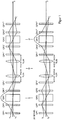
- the quadrupole fields are denoted as QP, the octupole fields as OP, and the transfer lenses as TL.
- the corrective is symmetric with respect to the quadrupole fields antisymmetric to the center plane M and within the first (second) correcting section symmetrical to the midplane S (S ').
- the object plane of the imaging system is imaged by the objective lens and possibly by a transfer lens system into the first quadrupole field QP 1 of the first correction piece. Accordingly, the axial fundamental tracks x y ⁇ ⁇ approximately pass through the center of the quadrupole field QP1 and do not experience any deflection.
- the off-axis fundamental orbits x ⁇ , y ⁇ become, after the two fundamental orbits run in different main sections, deflected in different directions.
- the next quadrupole field QP 2 adjoining in the direction of the beam path along the optical axis deflects the offaxial fundamental paths x ⁇ and y ⁇ in such a way that they pass through the center of the optical axis in the third quadrupole field QP 3.
- This third quadrupole field QP 3 has a combined electromag- netic structure so that, while maintaining its overall strength and adjusting the proportion of electric and magnetic quadrupole field strength, it is possible to influence and eliminate the axial color error of the first order and the first degree.
- the transfer lens system TL2 which consists of two spaced apart at 2f identical round lenses TL21 and TL22 focal length f. They form a 4f system in which the input image plane represents the midplane of the last quadrupole field QP1 'of the first correction patch and the output image plane represents the midplane of the first quadrupole field QP1 "of the second patch.
- the spatial arrangement, neglecting the polarity, is the same for the individual multipole elements, so that in the xz-section one obtains a beam path in the second correction piece that corresponds to the yz-cut in the first correction piece (and vice versa).
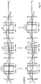
- FIG. 2 shows the arrangement of the octupole fields in the FIG. 1 described corrective. The construction thus agrees with that in FIG. 1 described so that reference is made to avoid repetition.
- An octupole field OP1, OP1 ' is superimposed on the quadrupole fields QP3, QP3', and another octupole field OP2 is located in the center plane of the corrective M.
- the described octopole fields are oriented symmetrically with respect to the plane M and are used for the complete correction of the 3rd order axial errors.
- octupole fields OP3, OP3' and OP3 ", OP3 '" are arranged.
- a pair of octopole fields OP4, OP4 ' is in the range between the transfer lenses TL21 / TL22.
- the octupole field OP2 arranged in the center plane of the corrective serves to correct the fourfold astigmatism of 3rd order.
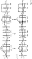
- FIG. 3 shows the arrangement of the octupole detector in the event that the correction of the fourfold astigmatism 3rd order by an arranged outside the corrective octopole field OP5.
- the structure agrees with the rest in FIG. 1 described so that reference is made to avoid repetition.
- the quadrupoles QP3, QP3 ' are each overlaid with an octupole field OP1, OP1'.
- a single additional transfer lens TL3 of focal length f joins the second correction patch a distance f from the center of its last quadrupole QP1 "'and produces an image of the center planes of the correction blocks S, S' spaced 2f from the center of QP1"', there is the octupole field OP5.
Landscapes
- Chemical & Material Sciences (AREA)
- Analytical Chemistry (AREA)
- Electron Beam Exposure (AREA)
Applications Claiming Priority (1)
| Application Number | Priority Date | Filing Date | Title |
|---|---|---|---|
| PCT/DE2005/002210 WO2007065382A1 (de) | 2005-12-06 | 2005-12-06 | Korrektiv zur beseitigung des öffnungsfehlers 3. ordnung und des axialen farbfehlers 1. ordnung 1. grades |
Publications (2)
| Publication Number | Publication Date |
|---|---|
| EP1958231A1 EP1958231A1 (de) | 2008-08-20 |
| EP1958231B1 true EP1958231B1 (de) | 2018-05-23 |
Family
ID=36729287
Family Applications (1)
| Application Number | Title | Priority Date | Filing Date |
|---|---|---|---|
| EP05816963.2A Active EP1958231B1 (de) | 2005-12-06 | 2005-12-06 | Korrektiv zur beseitigung des öffnungsfehlers 3. ordnung und des axialen farbfehlers 1. ordnung 1. grades |
Country Status (5)
| Country | Link |
|---|---|
| US (1) | US7989776B2 (ja) |
| EP (1) | EP1958231B1 (ja) |
| JP (1) | JP4848017B2 (ja) |
| DE (1) | DE112005003818A5 (ja) |
| WO (1) | WO2007065382A1 (ja) |
Families Citing this family (16)
| Publication number | Priority date | Publication date | Assignee | Title |
|---|---|---|---|---|
| JP4851268B2 (ja) * | 2006-08-31 | 2012-01-11 | 日本電子株式会社 | 収差補正方法および電子線装置 |
| DE102007007923A1 (de) * | 2007-02-14 | 2008-08-21 | Carl Zeiss Nts Gmbh | Phasenschiebendes Element und Teilchenstrahlgerät mit phasenschiebenden Element |
| DE102007045874A1 (de) | 2007-09-25 | 2009-04-02 | Ceos Corrected Electron Optical Systems Gmbh | Multipolspulen |
| DE102007049816B3 (de) | 2007-10-20 | 2009-04-16 | Ceos Corrected Electron Optical Systems Gmbh | Korrektor |
| DE102007058443B4 (de) * | 2007-12-05 | 2010-05-06 | Ceos Corrected Electron Optical Systems Gmbh | Korrektor für axialen und außeraxialen Strahlengang und TEM damit |
| DE102009010774A1 (de) * | 2009-02-26 | 2010-11-11 | Ceos Corrected Electron Optical Systems Gmbh | Verfahren und Vorrichtung zur Bildkontrasterzeugung durch Phasenschiebung |
| US8373136B2 (en) * | 2009-10-15 | 2013-02-12 | Ict Integrated Circuit Testing Gesellschaft Fur Halbleiterpruftechnik Mbh | Achromatic beam deflector, achromatic beam separator, charged particle device, method of operating an achromatic beam deflector, and method of operating an achromatic beam separator |
| DE102010054541A1 (de) * | 2010-12-15 | 2012-06-21 | Ceos Corrected Electron Optical Systems Gmbh | Korrektor |
| DE102011009954A1 (de) * | 2011-02-01 | 2012-08-02 | Ceos Corrected Electron Optical Systems Gmbh | Korrektor |
| US8536538B2 (en) * | 2011-02-16 | 2013-09-17 | Kla-Tencor Corporation | Multiple-pole electrostatic deflector for improving throughput of focused electron beam instruments |
| JP2013030374A (ja) * | 2011-07-29 | 2013-02-07 | Jeol Ltd | 電子顕微鏡 |
| JP5934517B2 (ja) * | 2012-02-24 | 2016-06-15 | 日本電子株式会社 | 色収差補正装置及び色収差補正装置の制御方法 |
| US9275817B2 (en) | 2012-04-09 | 2016-03-01 | Frederick Wight Martin | Particle-beam column corrected for both chromatic and spherical aberration |
| US8541755B1 (en) * | 2012-05-09 | 2013-09-24 | Jeol Ltd. | Electron microscope |
| US10103004B2 (en) | 2015-07-02 | 2018-10-16 | ICT Integrated Circuit Testing Gesellschaft für Halbleiterprüftechnik mbH | System and method for imaging a secondary charged particle beam with adaptive secondary charged particle optics |
| JP6647854B2 (ja) * | 2015-12-22 | 2020-02-14 | 日本電子株式会社 | 収差補正方法および荷電粒子線装置 |
Family Cites Families (5)
| Publication number | Priority date | Publication date | Assignee | Title |
|---|---|---|---|---|
| DE10001277A1 (de) | 2000-01-14 | 2001-07-19 | Harald Rose | Elektronenoptischer Korrektor zur Beseitigung der Bildfehler dritter Ordnung |
| DE10159454B4 (de) * | 2001-12-04 | 2012-08-02 | Carl Zeiss Nts Gmbh | Korrektor zur Korrektion von Farbfehlern erster Ordnung, ersten Grades |
| DE10159308A1 (de) * | 2001-12-04 | 2003-06-12 | Ceos Gmbh | Teilchenoptischer Korrektor |
| JP4204902B2 (ja) * | 2002-06-28 | 2009-01-07 | 日本電子株式会社 | 収差補正装置を備えた荷電粒子ビーム装置 |
| US6770887B2 (en) * | 2002-07-08 | 2004-08-03 | Ondrej L. Krivanek | Aberration-corrected charged-particle optical apparatus |
-
2005
- 2005-12-06 EP EP05816963.2A patent/EP1958231B1/de active Active
- 2005-12-06 US US12/096,579 patent/US7989776B2/en active Active
- 2005-12-06 DE DE112005003818T patent/DE112005003818A5/de not_active Withdrawn
- 2005-12-06 JP JP2008543639A patent/JP4848017B2/ja active Active
- 2005-12-06 WO PCT/DE2005/002210 patent/WO2007065382A1/de active Application Filing
Non-Patent Citations (1)
| Title |
|---|
| None * |
Also Published As
| Publication number | Publication date |
|---|---|
| EP1958231A1 (de) | 2008-08-20 |
| WO2007065382A1 (de) | 2007-06-14 |
| US20080283749A1 (en) | 2008-11-20 |
| US7989776B2 (en) | 2011-08-02 |
| JP2009518784A (ja) | 2009-05-07 |
| JP4848017B2 (ja) | 2011-12-28 |
| DE112005003818A5 (de) | 2008-11-13 |
Similar Documents
| Publication | Publication Date | Title |
|---|---|---|
| EP1958231B1 (de) | Korrektiv zur beseitigung des öffnungsfehlers 3. ordnung und des axialen farbfehlers 1. ordnung 1. grades | |
| EP0530640B1 (de) | Abbildungssystem für Strahlung geladener Teilchen mit Spiegelkorrektor | |
| EP0617451B1 (de) | Abbildendes Elektronenenergiefilter | |
| EP1362361B1 (de) | Teilchenstrahlsystem mit einem spiegelkorrektor | |
| DE69822139T2 (de) | Korrekturvorrichtung zur linsenfehlerkorrektur in ladungsträger-optischen geräten | |
| EP1057204B1 (de) | Anordnung zur korrektur des öffnungsfehlers dritter ordnung einer linse, insbesondere der objektivlinse eines elektronenmikroskops | |
| EP1220292B1 (de) | Monochromator für geladene Teilchen | |
| DE10159454B4 (de) | Korrektor zur Korrektion von Farbfehlern erster Ordnung, ersten Grades | |
| DE69733873T2 (de) | Vorrichtung zur korrektur von linsenfehlern in teilchen-optischer geräte | |
| DE112014003890B4 (de) | Mit einem Strahl geladener Teilchen arbeitende Vorrichtung | |
| EP2068344B1 (de) | Teilchenoptischer Korrektor für axialen und ausseraxialen Strahlengang | |
| EP0967630B1 (de) | Elektronenmikroskop mit einem abbildenden magnetischen Energiefilter | |
| DE102007024353B4 (de) | Monochromator und Strahlquelle mit Monochromator | |
| EP1249031B1 (de) | Elektronenoptischer korrektor zur beseitigung der bildfehler dritter ordnung | |
| DE102020107738B3 (de) | Teilchenstrahl-System mit einer Multipol-Linsen-Sequenz zur unabhängigen Fokussierung einer Vielzahl von Einzel-Teilchenstrahlen, seine Verwendung und zugehöriges Verfahren | |
| EP1941531B1 (de) | Elektronenoptischer korrektor für aplanatische abbildungssysteme | |
| EP2051279B1 (de) | Korrektor | |
| DE10122957B4 (de) | Teilchenstrahlapparat mit energiekorrigierter Strahlablenkung sowie Vorrichtungund Verfahren zur energiekorrigierten Ablenkung eines Teilchenstrahls | |
| EP1451847B1 (de) | Teilchenoptischer korrektor | |
| EP3780064B1 (de) | Teilchenoptischer korrektor frei von axialen fehlern sechster ordnung und elektronenmikroskop mit korrektor | |
| DE2213208A1 (de) | Korpuskularstrahloptisches abbildungssystem | |
| EP1124251A2 (de) | Elektronenerergiefilter mit magnetischen Umlenkbereichen | |
| EP2466613A2 (de) | Korrektor | |
| EP1352410B1 (de) | Elektrostatischer korrektor | |
| DE112021004508T5 (de) | Aberrationskorrektor und elektronenmikroskop |
Legal Events
| Date | Code | Title | Description |
|---|---|---|---|
| PUAI | Public reference made under article 153(3) epc to a published international application that has entered the european phase |
Free format text: ORIGINAL CODE: 0009012 |
|
| 17P | Request for examination filed |
Effective date: 20080605 |
|
| AK | Designated contracting states |
Kind code of ref document: A1 Designated state(s): AT BE BG CH CY CZ DE DK EE ES FI FR GB GR HU IE IS IT LI LT LU LV MC NL PL PT RO SE SI SK TR |
|
| RIN1 | Information on inventor provided before grant (corrected) |
Inventor name: MUELLER, HEIKO Inventor name: UHLEMANN, STEPHAN Inventor name: ROSE, HARALD |
|
| DAX | Request for extension of the european patent (deleted) | ||
| 17Q | First examination report despatched |
Effective date: 20160708 |
|
| GRAP | Despatch of communication of intention to grant a patent |
Free format text: ORIGINAL CODE: EPIDOSNIGR1 |
|
| INTG | Intention to grant announced |
Effective date: 20180205 |
|
| GRAS | Grant fee paid |
Free format text: ORIGINAL CODE: EPIDOSNIGR3 |
|
| GRAA | (expected) grant |
Free format text: ORIGINAL CODE: 0009210 |
|
| AK | Designated contracting states |
Kind code of ref document: B1 Designated state(s): AT BE BG CH CY CZ DE DK EE ES FI FR GB GR HU IE IS IT LI LT LU LV MC NL PL PT RO SE SI SK TR |
|
| REG | Reference to a national code |
Ref country code: GB Ref legal event code: FG4D Free format text: NOT ENGLISH |
|
| REG | Reference to a national code |
Ref country code: CH Ref legal event code: EP |
|
| REG | Reference to a national code |
Ref country code: IE Ref legal event code: FG4D Free format text: LANGUAGE OF EP DOCUMENT: GERMAN |
|
| REG | Reference to a national code |
Ref country code: DE Ref legal event code: R096 Ref document number: 502005015837 Country of ref document: DE |
|
| REG | Reference to a national code |
Ref country code: AT Ref legal event code: REF Ref document number: 1002175 Country of ref document: AT Kind code of ref document: T Effective date: 20180615 |
|
| REG | Reference to a national code |
Ref country code: NL Ref legal event code: FP |
|
| REG | Reference to a national code |
Ref country code: LT Ref legal event code: MG4D |
|
| PG25 | Lapsed in a contracting state [announced via postgrant information from national office to epo] |
Ref country code: SE Free format text: LAPSE BECAUSE OF FAILURE TO SUBMIT A TRANSLATION OF THE DESCRIPTION OR TO PAY THE FEE WITHIN THE PRESCRIBED TIME-LIMIT Effective date: 20180523 Ref country code: LT Free format text: LAPSE BECAUSE OF FAILURE TO SUBMIT A TRANSLATION OF THE DESCRIPTION OR TO PAY THE FEE WITHIN THE PRESCRIBED TIME-LIMIT Effective date: 20180523 Ref country code: ES Free format text: LAPSE BECAUSE OF FAILURE TO SUBMIT A TRANSLATION OF THE DESCRIPTION OR TO PAY THE FEE WITHIN THE PRESCRIBED TIME-LIMIT Effective date: 20180523 Ref country code: BG Free format text: LAPSE BECAUSE OF FAILURE TO SUBMIT A TRANSLATION OF THE DESCRIPTION OR TO PAY THE FEE WITHIN THE PRESCRIBED TIME-LIMIT Effective date: 20180823 Ref country code: FI Free format text: LAPSE BECAUSE OF FAILURE TO SUBMIT A TRANSLATION OF THE DESCRIPTION OR TO PAY THE FEE WITHIN THE PRESCRIBED TIME-LIMIT Effective date: 20180523 |
|
| PG25 | Lapsed in a contracting state [announced via postgrant information from national office to epo] |
Ref country code: GR Free format text: LAPSE BECAUSE OF FAILURE TO SUBMIT A TRANSLATION OF THE DESCRIPTION OR TO PAY THE FEE WITHIN THE PRESCRIBED TIME-LIMIT Effective date: 20180824 Ref country code: LV Free format text: LAPSE BECAUSE OF FAILURE TO SUBMIT A TRANSLATION OF THE DESCRIPTION OR TO PAY THE FEE WITHIN THE PRESCRIBED TIME-LIMIT Effective date: 20180523 |
|
| PG25 | Lapsed in a contracting state [announced via postgrant information from national office to epo] |
Ref country code: PL Free format text: LAPSE BECAUSE OF FAILURE TO SUBMIT A TRANSLATION OF THE DESCRIPTION OR TO PAY THE FEE WITHIN THE PRESCRIBED TIME-LIMIT Effective date: 20180523 Ref country code: SK Free format text: LAPSE BECAUSE OF FAILURE TO SUBMIT A TRANSLATION OF THE DESCRIPTION OR TO PAY THE FEE WITHIN THE PRESCRIBED TIME-LIMIT Effective date: 20180523 Ref country code: RO Free format text: LAPSE BECAUSE OF FAILURE TO SUBMIT A TRANSLATION OF THE DESCRIPTION OR TO PAY THE FEE WITHIN THE PRESCRIBED TIME-LIMIT Effective date: 20180523 Ref country code: DK Free format text: LAPSE BECAUSE OF FAILURE TO SUBMIT A TRANSLATION OF THE DESCRIPTION OR TO PAY THE FEE WITHIN THE PRESCRIBED TIME-LIMIT Effective date: 20180523 Ref country code: EE Free format text: LAPSE BECAUSE OF FAILURE TO SUBMIT A TRANSLATION OF THE DESCRIPTION OR TO PAY THE FEE WITHIN THE PRESCRIBED TIME-LIMIT Effective date: 20180523 |
|
| REG | Reference to a national code |
Ref country code: DE Ref legal event code: R097 Ref document number: 502005015837 Country of ref document: DE |
|
| PG25 | Lapsed in a contracting state [announced via postgrant information from national office to epo] |
Ref country code: IT Free format text: LAPSE BECAUSE OF FAILURE TO SUBMIT A TRANSLATION OF THE DESCRIPTION OR TO PAY THE FEE WITHIN THE PRESCRIBED TIME-LIMIT Effective date: 20180523 |
|
| PLBE | No opposition filed within time limit |
Free format text: ORIGINAL CODE: 0009261 |
|
| STAA | Information on the status of an ep patent application or granted ep patent |
Free format text: STATUS: NO OPPOSITION FILED WITHIN TIME LIMIT |
|
| 26N | No opposition filed |
Effective date: 20190226 |
|
| PG25 | Lapsed in a contracting state [announced via postgrant information from national office to epo] |
Ref country code: SI Free format text: LAPSE BECAUSE OF FAILURE TO SUBMIT A TRANSLATION OF THE DESCRIPTION OR TO PAY THE FEE WITHIN THE PRESCRIBED TIME-LIMIT Effective date: 20180523 |
|
| REG | Reference to a national code |
Ref country code: CH Ref legal event code: PL |
|
| PG25 | Lapsed in a contracting state [announced via postgrant information from national office to epo] |
Ref country code: MC Free format text: LAPSE BECAUSE OF FAILURE TO SUBMIT A TRANSLATION OF THE DESCRIPTION OR TO PAY THE FEE WITHIN THE PRESCRIBED TIME-LIMIT Effective date: 20180523 Ref country code: LU Free format text: LAPSE BECAUSE OF NON-PAYMENT OF DUE FEES Effective date: 20181206 |
|
| REG | Reference to a national code |
Ref country code: IE Ref legal event code: MM4A |
|
| REG | Reference to a national code |
Ref country code: BE Ref legal event code: MM Effective date: 20181231 |
|
| PG25 | Lapsed in a contracting state [announced via postgrant information from national office to epo] |
Ref country code: FR Free format text: LAPSE BECAUSE OF NON-PAYMENT OF DUE FEES Effective date: 20181231 Ref country code: IE Free format text: LAPSE BECAUSE OF NON-PAYMENT OF DUE FEES Effective date: 20181206 |
|
| PG25 | Lapsed in a contracting state [announced via postgrant information from national office to epo] |
Ref country code: BE Free format text: LAPSE BECAUSE OF NON-PAYMENT OF DUE FEES Effective date: 20181231 |
|
| PG25 | Lapsed in a contracting state [announced via postgrant information from national office to epo] |
Ref country code: CH Free format text: LAPSE BECAUSE OF NON-PAYMENT OF DUE FEES Effective date: 20181231 Ref country code: LI Free format text: LAPSE BECAUSE OF NON-PAYMENT OF DUE FEES Effective date: 20181231 |
|
| REG | Reference to a national code |
Ref country code: AT Ref legal event code: MM01 Ref document number: 1002175 Country of ref document: AT Kind code of ref document: T Effective date: 20181206 |
|
| PG25 | Lapsed in a contracting state [announced via postgrant information from national office to epo] |
Ref country code: TR Free format text: LAPSE BECAUSE OF FAILURE TO SUBMIT A TRANSLATION OF THE DESCRIPTION OR TO PAY THE FEE WITHIN THE PRESCRIBED TIME-LIMIT Effective date: 20180523 |
|
| PG25 | Lapsed in a contracting state [announced via postgrant information from national office to epo] |
Ref country code: AT Free format text: LAPSE BECAUSE OF NON-PAYMENT OF DUE FEES Effective date: 20181206 |
|
| PG25 | Lapsed in a contracting state [announced via postgrant information from national office to epo] |
Ref country code: PT Free format text: LAPSE BECAUSE OF FAILURE TO SUBMIT A TRANSLATION OF THE DESCRIPTION OR TO PAY THE FEE WITHIN THE PRESCRIBED TIME-LIMIT Effective date: 20180523 |
|
| PG25 | Lapsed in a contracting state [announced via postgrant information from national office to epo] |
Ref country code: CY Free format text: LAPSE BECAUSE OF FAILURE TO SUBMIT A TRANSLATION OF THE DESCRIPTION OR TO PAY THE FEE WITHIN THE PRESCRIBED TIME-LIMIT Effective date: 20180523 Ref country code: HU Free format text: LAPSE BECAUSE OF FAILURE TO SUBMIT A TRANSLATION OF THE DESCRIPTION OR TO PAY THE FEE WITHIN THE PRESCRIBED TIME-LIMIT; INVALID AB INITIO Effective date: 20051206 |
|
| PG25 | Lapsed in a contracting state [announced via postgrant information from national office to epo] |
Ref country code: IS Free format text: LAPSE BECAUSE OF FAILURE TO SUBMIT A TRANSLATION OF THE DESCRIPTION OR TO PAY THE FEE WITHIN THE PRESCRIBED TIME-LIMIT Effective date: 20180923 |
|
| REG | Reference to a national code |
Ref country code: DE Ref legal event code: R082 Ref document number: 502005015837 Country of ref document: DE Representative=s name: ALTMANN STOESSEL DICK PATENTANWAELTE PARTG MBB, DE |
|
| PGFP | Annual fee paid to national office [announced via postgrant information from national office to epo] |
Ref country code: GB Payment date: 20231218 Year of fee payment: 19 |
|
| PGFP | Annual fee paid to national office [announced via postgrant information from national office to epo] |
Ref country code: NL Payment date: 20231220 Year of fee payment: 19 Ref country code: CZ Payment date: 20231122 Year of fee payment: 19 |
|
| PGFP | Annual fee paid to national office [announced via postgrant information from national office to epo] |
Ref country code: DE Payment date: 20231221 Year of fee payment: 19 |