EP1956411A2 - Filtre de protection contre l'éblouissement électro-optique et unité de protection contre l'éblouissement pour un dispositif de protection contre l'éblouissement portatif - Google Patents
Filtre de protection contre l'éblouissement électro-optique et unité de protection contre l'éblouissement pour un dispositif de protection contre l'éblouissement portatif Download PDFInfo
- Publication number
- EP1956411A2 EP1956411A2 EP07405282A EP07405282A EP1956411A2 EP 1956411 A2 EP1956411 A2 EP 1956411A2 EP 07405282 A EP07405282 A EP 07405282A EP 07405282 A EP07405282 A EP 07405282A EP 1956411 A2 EP1956411 A2 EP 1956411A2
- Authority
- EP
- European Patent Office
- Prior art keywords
- orientation
- liquid crystal
- polarizer
- electro
- layer
- Prior art date
- Legal status (The legal status is an assumption and is not a legal conclusion. Google has not performed a legal analysis and makes no representation as to the accuracy of the status listed.)
- Withdrawn
Links
Images


Classifications
-
- G—PHYSICS
- G02—OPTICS
- G02F—OPTICAL DEVICES OR ARRANGEMENTS FOR THE CONTROL OF LIGHT BY MODIFICATION OF THE OPTICAL PROPERTIES OF THE MEDIA OF THE ELEMENTS INVOLVED THEREIN; NON-LINEAR OPTICS; FREQUENCY-CHANGING OF LIGHT; OPTICAL LOGIC ELEMENTS; OPTICAL ANALOGUE/DIGITAL CONVERTERS
- G02F1/00—Devices or arrangements for the control of the intensity, colour, phase, polarisation or direction of light arriving from an independent light source, e.g. switching, gating or modulating; Non-linear optics
- G02F1/01—Devices or arrangements for the control of the intensity, colour, phase, polarisation or direction of light arriving from an independent light source, e.g. switching, gating or modulating; Non-linear optics for the control of the intensity, phase, polarisation or colour
- G02F1/13—Devices or arrangements for the control of the intensity, colour, phase, polarisation or direction of light arriving from an independent light source, e.g. switching, gating or modulating; Non-linear optics for the control of the intensity, phase, polarisation or colour based on liquid crystals, e.g. single liquid crystal display cells
- G02F1/133—Constructional arrangements; Operation of liquid crystal cells; Circuit arrangements
- G02F1/1333—Constructional arrangements; Manufacturing methods
- G02F1/1347—Arrangement of liquid crystal layers or cells in which the final condition of one light beam is achieved by the addition of the effects of two or more layers or cells
- G02F1/13471—Arrangement of liquid crystal layers or cells in which the final condition of one light beam is achieved by the addition of the effects of two or more layers or cells in which all the liquid crystal cells or layers remain transparent, e.g. FLC, ECB, DAP, HAN, TN, STN, SBE-LC cells
-
- A—HUMAN NECESSITIES
- A61—MEDICAL OR VETERINARY SCIENCE; HYGIENE
- A61F—FILTERS IMPLANTABLE INTO BLOOD VESSELS; PROSTHESES; DEVICES PROVIDING PATENCY TO, OR PREVENTING COLLAPSING OF, TUBULAR STRUCTURES OF THE BODY, e.g. STENTS; ORTHOPAEDIC, NURSING OR CONTRACEPTIVE DEVICES; FOMENTATION; TREATMENT OR PROTECTION OF EYES OR EARS; BANDAGES, DRESSINGS OR ABSORBENT PADS; FIRST-AID KITS
- A61F9/00—Methods or devices for treatment of the eyes; Devices for putting-in contact lenses; Devices to correct squinting; Apparatus to guide the blind; Protective devices for the eyes, carried on the body or in the hand
- A61F9/04—Eye-masks ; Devices to be worn on the face, not intended for looking through; Eye-pads for sunbathing
- A61F9/06—Masks, shields or hoods for welders
- A61F9/065—Masks, shields or hoods for welders use of particular optical filters
-
- G—PHYSICS
- G02—OPTICS
- G02F—OPTICAL DEVICES OR ARRANGEMENTS FOR THE CONTROL OF LIGHT BY MODIFICATION OF THE OPTICAL PROPERTIES OF THE MEDIA OF THE ELEMENTS INVOLVED THEREIN; NON-LINEAR OPTICS; FREQUENCY-CHANGING OF LIGHT; OPTICAL LOGIC ELEMENTS; OPTICAL ANALOGUE/DIGITAL CONVERTERS
- G02F1/00—Devices or arrangements for the control of the intensity, colour, phase, polarisation or direction of light arriving from an independent light source, e.g. switching, gating or modulating; Non-linear optics
- G02F1/01—Devices or arrangements for the control of the intensity, colour, phase, polarisation or direction of light arriving from an independent light source, e.g. switching, gating or modulating; Non-linear optics for the control of the intensity, phase, polarisation or colour
- G02F1/13—Devices or arrangements for the control of the intensity, colour, phase, polarisation or direction of light arriving from an independent light source, e.g. switching, gating or modulating; Non-linear optics for the control of the intensity, phase, polarisation or colour based on liquid crystals, e.g. single liquid crystal display cells
- G02F1/133—Constructional arrangements; Operation of liquid crystal cells; Circuit arrangements
- G02F1/1333—Constructional arrangements; Manufacturing methods
- G02F1/1335—Structural association of cells with optical devices, e.g. polarisers or reflectors
- G02F1/133528—Polarisers
- G02F1/133531—Polarisers characterised by the arrangement of polariser or analyser axes
Definitions
- the invention relates to the field of anti-glare devices, as used, for example, as welding protection masks or helmets, and more particularly to an electro-optical anti-glare filter and to a glare protection unit for a portable anti-glare device according to the preamble of the corresponding independent claims.
- Anti-glare units for portable anti-glare devices such as protective masks and goggles are well known.
- Modern antiglare devices have electro-optical filters, for example with a liquid crystal element whose permeability is adjusted automatically or manually.
- Such a filter should, in addition to a predetermined and optionally adjustable protection level, also have the lowest possible viewing angle dependence.
- WO 2004/102265 The goal is to achieve a symmetrical viewing angle dependence with respect to the normal to the LCD element of an anti-glare filter.
- the viewing angle dependence is due to the birefringence in the LCD cell recycled.
- a negative-birefringent compensation layer this is compensated.
- the parameters of the cell and the compensation layer must be matched, and the cell must be a HT (higly twisted) cell, passing through as few as possible a single mode of light.
- US Pat. No. 5,515,186 describes a welding mask with arrangements of polarizers which are matched to one another in such a way that a region which appears brighter in a combination of two polarizers appears again darkened in combination with another polarizer.
- the liquid crystal cells are of the type expressly cells which operate on the basis of switchable birefringence, in contrast to "twisted nematic" or TN cells in which the polarization is rotated.
- a polarizer angle other than 90 ° can be selected to compensate for residual birefringence so that a maximum contrast is achieved at a viewing angle perpendicular to the cells.
- US 6,327,010 shows an optical filter with a TN liquid crystal cell and a compensation layer of different types of liquid crystals. There are only one or two polarization layers in the whole filter. The arrangement is intended for use in LCD displays. High values for contrast and / or brightness and / or the viewing angle independence of contrast and / or color should be achieved. In one embodiment, this is achieved by having in a liquid crystal cell two polarizers which are rotated by 90 ° ⁇ 10 ° to each other, the angle between the polarizers and the rubbing directions of the TN cell corresponds to certain conditions, and at least one compensation layer to compensate for differences is present in the optical path of the liquid crystal cell.
- WO 95/29428 shows an antiglare filter with a combination of two liquid crystal cells, in a mutually rotated arrangement, wherein the two liquid crystal cells are each arranged between two mutually extinguishing polarization filters.
- the liquid crystal cells consist of Low Twisted Nematic (LTN) cells, such as those from FR2728358 . US4952030 and US4609255 are known.
- LTN Low Twisted Nematic
- WO 97/15255 describes a single or two liquid crystal cells whose polarizers are each mutually extinguishing respectively perpendicular to each other. In order to reduce the viewing angle dependence, a retard film is disposed between two of the polarizers.
- WO 99/53367 shows a configuration for a single liquid crystal cell of a screen.
- the cell has - in this sequence - a first polarizer, a first compensator, which in turn consists of two layers, a liquid crystal layer, a second (two-layer) compensator and a second polarizer.
- the two polarizers are not crossed with each other, but rotated by 2 ° to 6 ° or 20 ° from the crossed position.
- the first and second compensators are also twisted from the crossed position, preferably at the same angle as the two polarizers.
- This object is achieved by an electro-optical anti-glare filter and a glare protection unit for a portable anti-glare device with the features of the corresponding independent claims.
- the electro-optical anti-glare filter thus has at least two successive (in the direction of the surface normal of the filter planes) arranged liquid crystal cells of the type "twisted nematic" (TN) with polarization layers, wherein the polarization directions of two polarization layers, which are each associated with a liquid crystal cell, are not parallel that is, rotated at least 45 ° to each other.
- the filter also has a drive device for the electrical control of the liquid crystal cells.
- the antiglare filter has at least two liquid crystal cells, wherein in exactly two of these liquid crystal cells, the polarization directions of the two polarization layers which are assigned to the respective liquid crystal cell are uncrossed.
- the two liquid crystal cells in their construction are at least approximately mirror-symmetrical to each other. Preferably, they use the same liquid crystals. This improves the symmetry of the viewing angle dependence with respect to the surface normal.
- the plane of symmetry lies in the spatial center of the two liquid crystal cells. If the cells divide the middle polarizer, the symmetry lies at the center of this polarizer. If the cells each have their own, separate polarizers in the center of the antiglare filter, then the plane of symmetry lies midway between these separate polarizers.
- the angle of rotation between the polarization directions of each two uncrossed polarization layers is preferably 82 ° to 89 °, in particular 85 ° to 88 °, wherein the acute angle between the polarization directions is authoritative.
- the bisector of the acute angle between the polarization directions of two crossed polarizers coincides with the bisector of the associated liquid crystal layer.
- double cells can be produced, which have a markedly lower variation of the protection level (shade number SN) within one Sight cone with an opening angle of 60 ° (that is, deviating in each direction by up to 30 ° from the surface normal of the filter) than conventional filters based on TN cells.
- shade number SN protection level within one Sight cone with an opening angle of 60 ° (that is, deviating in each direction by up to 30 ° from the surface normal of the filter) than conventional filters based on TN cells.
- the drive means for feeding the liquid crystal cells on a non-linearity for compensating a non-linear voltage dimming ratio of the liquid crystal cells is preferably arranged in the control value determination, and is thus - in the signal flow path - preceded by the non-linearity of the cells.
- a glare protection unit for a portable anti-glare device has an electro-optical anti-glare filter according to the invention.
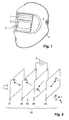
- FIG. 1 shows a welder protection mask 4 with a glare protection cassette 1.
- the anti-glare cassette 1 is arranged interchangeably behind a likewise replaceable protective plate 3.
- the anti-glare cartridge 1 has an electro-optical filter 2, also called a shutter.
- the filter 2 is controlled by a control electronics 5 (in FIG. 1 not visible), which drive electronics 5 is preferably fed by a battery and / or a solar cell.
- the activation preferably takes place in accordance with a quantity of light which is detected by sensors on the front side of the anti-glare cassette 1.
- a flicker circuit is preferably used to detect the arc of a welding process, so that the filter 2 is darkened when a welding operation occurs.
- the darkening can only be switched on and off, but it is also possible to regulate the intensity of the darkening, for example according to the ambient brightness, the intensity of the arc, a user specification, etc.
- FIG. 2 shows a layer sequence of a liquid crystal cell 20.
- Light indicated by a block arrow, falls in the direction of a z-axis in the cell.
- the various layers of the cell each extend in planes parallel to x and y directions.
- the liquid crystal cell 20 has, viewed in the direction of the incident light, a first polarizer 21, followed by a substrate having a first orientation layer 22 and a substrate having a second orientation layer 24.
- the orientation layers are used in a known manner for orientation of the liquid crystal molecules at the boundary to the respective substrate. Between the orientation layers 22, 24 there is a gap with a liquid crystal layer 23. Next to the second orientation layer 24, a second polarizer 25 is arranged.
- the two substrates 22, 24 are formed as electrodes for driving the liquid crystal layer 23 and are electrically connected to the drive electronics 5 and controlled by them.
- the characteristic orientations of the polarizers and orientation layers are indicated by arrows.
- the directions of the first and second orientation layers 22, 24 are denoted by R1 and R2.
- the substrates in turn are mounted between two polarizers.
- the polarization directions of the first and second polarization layers 21, 25 are oriented along the directions P1 and P2
- FIGS. 3, 4 and 5 show the directions of the polarizers and orientation layers of a liquid crystal cell in the projection on the x / y plane.
- the mutual rotation of the polarization directions P1, P2 is denoted by ⁇ .
- the angle is defined as the smaller of the two possible twist angle, and thus can be a maximum of 90 °.
- the mutual rotation of the orientation directions R1, R2 is denoted by ⁇ , and is also called "twist" of the liquid crystal cell.
- Targeted decoupling of the polarizers such that, for example, 82 ° ⁇ ⁇ 89 ° results in a changed viewing angle dependence of the individual cell.
- the darkening is amplified, typically in an angle range between 5 ° and 45 ° away from the surface normal.
- the enhanced darkening of the first cell compensates for the zones of attenuated darkening of the second cell, and vice versa.
- the bisector of the twist angle ⁇ is denoted by BR
- the angle between the two bisectors is denoted by ⁇ .
- the angle between the bisectors is small, for example ⁇ ⁇ 45 °, or even the bisectors are at least approximately parallel, for example in the range 0 ° ⁇ ⁇ 20 °.
- FIG. 4 shows FIG. 4 in which the "X-buffed" configuration has been selected, ie, in which the orientations of the polarizers are at least approximately perpendicular to those of the respective adjacent orientation layers.
- FIG. 5 shows a further embodiment in the X-buffed configuration, in which a low twisted nematic cell, with ⁇ ⁇ 85 °, is used.
- FIG. 6 shows a layer sequence of a double liquid crystal cell, wherein both the first liquid crystal cell 20 and a second liquid crystal cell 30 are desiccated.
- the second liquid crystal cell 30 divides the second polarizer 25 with the first liquid crystal cell 20 and has further substrates with a third orientation layer 32 and a fourth orientation layer 34, between which a second gap with a second liquid crystal layer 33 is located.
- a third polarizer 35 is then arranged on the fourth orientation layer 34.
- the two substrates 32, 34 are formed as electrodes for driving the second liquid crystal layer 33 and are electrically connected to the control electronics 5 or with a further control electronics 5 'and controlled by them.
- P1 and R1 are substantially parallel, as well as P2 and R2, as shown in the P-buffed cell shown.
- P1 and R1 as well as P2 and R2, would each be substantially perpendicular to each other.
- the arrangement of the two cells is thus mirror-symmetrical to each other, and the two liquid crystal cells are filled with liquid crystals of different rotation (chirality).
- the plane of symmetry is located in the middle between the two cells or the common polarizer 25.
- FIG. 7 shows a layer sequence of a double liquid crystal cell in another preferred embodiment of the invention.
- the second polarizer 25 is not common to both cells 20, 30, but the second liquid crystal cell 30 has a further middle (or a fourth) polarizer 31, which is arranged between the second polarizer 25 and the third orientation layer 32.
- the fourth polarizer 31 has an orientation P2 'which is substantially parallel to the orientation P2.
- the two cells 20, 30 can therefore be manufactured and tested separately from each other and only then combined into a double cell.
- the respective direction pairs which have been referred to as "at least approximately parallel", such as P1 and P1 ', deliberately shown as slightly rotated against each other.
- the mutual rotation is for example less than +/- 20 °. This applies both to the mutual rotation of the orientation layers and to the mutual rotation of the polarizers.
- the in the FIG. 8 uses two X-buffed LTN cells, which are in the FIG. 9
- the configuration shown uses two cells of type X-buffed TN.
- the above information is also valid for both P-buffed and TN or LTN types to produce a dual cell according to the invention.
- only one of the two cells of a double cell is uncrossed.
- an asymmetric viewing angle dependence is achieved, which may be interesting in eye protection, since the vertical field of view of the eyes upwards is significantly smaller than downwards.
- one cell is aligned so that the "best viewing direction" points down.
- This cell is designed with uncrossed polarizers.
- the other cell is a standard cell with crossed polarizers whose "best viewing direction" points upwards. In this case, the "best viewing direction" of a cell points approximately in the direction of the bisecting line BR of the assigned orientation layers.
- the cells of the embodiments presented so far are preferably of the Twisted Nematic (TN) type with a twist, that is to say with an angle ⁇ between the orientation layers, between 70 ° ⁇ ⁇ 110 °, the direction of the twist in the one cell being the direction in the other cell is opposite.
- TN Twisted Nematic
- the decrossed cell (s) of the embodiments presented so far are "low twisted nematic" (LTN) cells with a twist of about 80 ° and preferably between 70 ° ⁇ ⁇ 85 °.
- LTN low twisted nematic
- the decrossed cell (s) are so-called X-buffed cells, i. Cells in which the orientation layers are each rotated by at least approximately 90 ° relative to the polarization directions of the respective nearest polarizers.
- the filter 2 consists of two symmetrical cells 20, 30, both of which are of the crossed-out type. They are preferably both driven with the same voltage and by the same control electronics 5. The at least two liquid crystal cells are thus connected to the same supply voltage source.
- FIG. 10 shows a course of a voltage obscuration dependency.
- the darkening SN shade number
- the course is typical of a mirror-symmetrical and arranged double TN cell in the X-buffed version with four polarizers, in which within the manufacturing tolerances the polarization directions P1 with P2 and P1 'with P2' and the rubbing directions R1 with R1 'and R2 coincide with R2 '.
- desired protection levels and selected components the nonlinearity is more or less pronounced, and in some cases can be omitted (for example, if the filter of FIG. 10 only operated until protection level 11).
- the cells are generally driven by a square-wave voltage that is symmetrical about the zero point. Typical frequencies of the square-wave signal are 40-50 Hz, but can also be up to and less than 1 Hz for energy-saving filters.
- a total of mirror-symmetrically arranged LTN liquid crystal cells in the X-buffed configuration are arranged, with a total of four polarizers, in which the characteristic angle ⁇ is at least approximately zero and in which the polarization directions P1 with P2 and P1 'with P2' and the rubbing directions R1 with R1 'and R2 coincide with R2'.
- the control for compensation has a non-linearity.
- this is, for example, a non-linear scaling of the position of an input means set by the user, for example a rotary knob or a slide control.
- the supply voltage is formed by a digital or analog electronics, which has stored a compensation characteristic.
- the compensation characteristic is shaped inversely to the voltage-dimming characteristic, so that the series connection of the compensation characteristic with the voltage-dimming characteristic results in a linear progression.
- the liquid crystal cells can also contain guest-host LCs in addition to the conventional TN or STN LC mixtures.
- the cells can be prepared in such a way that a low anchoring energy of the edge molecules is achieved, as for example in the European patent application with the application number 06 405 072 the same applicant is described.
- the cells may also be combined with other components, for example with additional guest-host LC mix filled cells, or other TN cells.
Applications Claiming Priority (1)
| Application Number | Priority Date | Filing Date | Title |
|---|---|---|---|
| CH14902006 | 2006-09-19 |
Publications (2)
| Publication Number | Publication Date |
|---|---|
| EP1956411A2 true EP1956411A2 (fr) | 2008-08-13 |
| EP1956411A3 EP1956411A3 (fr) | 2009-03-18 |
Family
ID=37763859
Family Applications (1)
| Application Number | Title | Priority Date | Filing Date |
|---|---|---|---|
| EP07405282A Withdrawn EP1956411A3 (fr) | 2006-09-19 | 2007-09-19 | Filtre de protection contre l'éblouissement électro-optique et unité de protection contre l'éblouissement pour un dispositif de protection contre l'éblouissement portatif |
Country Status (2)
| Country | Link |
|---|---|
| US (1) | US20080068521A1 (fr) |
| EP (1) | EP1956411A3 (fr) |
Families Citing this family (9)
| Publication number | Priority date | Publication date | Assignee | Title |
|---|---|---|---|---|
| CN102579189A (zh) * | 2011-01-12 | 2012-07-18 | 玛斯克光电科技股份有限公司 | 电焊滤镜装置及其控制方法 |
| CN102349845B (zh) * | 2011-09-05 | 2013-07-03 | 天马微电子股份有限公司 | 电焊护目镜 |
| US20140215673A1 (en) * | 2013-02-07 | 2014-08-07 | 3M Innovative Properties Company | Protective headgear and optical-filter cartridge removably mountable thereto |
| CN104107107A (zh) * | 2013-04-19 | 2014-10-22 | 李骥超 | 一种自动变光焊接面罩中护目镜组结构 |
| CN103995382A (zh) * | 2014-04-23 | 2014-08-20 | 河北冀雅电子有限公司 | 一种电焊护目镜的制造方法 |
| US10098788B2 (en) | 2014-12-22 | 2018-10-16 | Optrel Holding AG | Electro-optical glare-protection filter with a liquid crystal cell being a fringe-field switching cell for a welder protection device |
| EP3326592A1 (fr) * | 2016-11-23 | 2018-05-30 | optrel Holding AG | Cassette de protection |
| KR102304918B1 (ko) * | 2019-09-20 | 2021-09-27 | 주식회사 오토스윙 | 광기능성층 및 패널 제어 기술이 적용된 용접용 보호구 |
| CN111694184B (zh) * | 2019-12-31 | 2023-03-24 | 冀雅(上海)电子销售有限公司 | 一种电焊护目镜用液晶光阀 |
Citations (8)
| Publication number | Priority date | Publication date | Assignee | Title |
|---|---|---|---|---|
| US4609255A (en) | 1983-07-01 | 1986-09-02 | U.S. Philips Corporation | Liquid crystal display with twist angle less than 80 degrees |
| US4952030A (en) | 1987-09-04 | 1990-08-28 | Asahi Glass Company, Ltd. | Liquid crystal display device with a 50°-80° twist angle |
| WO1995029428A1 (fr) | 1994-04-26 | 1995-11-02 | Hörnell Elektrooptik Ab | Ecrans de soudage en verre a cristaux liquides presentant des proprietes angulaires optiques ameliorees |
| FR2728358A1 (fr) | 1994-12-15 | 1996-06-21 | Sagem | Afficheur a cristaux liquides a matrice active |
| WO1997015255A1 (fr) | 1995-10-26 | 1997-05-01 | Hörnell International AB | Obturateur a cristaux liquides et dispositif pourvu d'un tel obturateur et servant d'ecran contre la lumiere |
| WO1999053367A1 (fr) | 1998-04-14 | 1999-10-21 | Thomson-Csf Sextant | Amelioration de l'angle de vue d'un ecran lcd |
| US6327010B1 (en) | 1992-02-03 | 2001-12-04 | Merck Patent Gesellschaft Mit Beschrankter Haftung | Electrooptical system |
| WO2004102265A1 (fr) | 2003-05-16 | 2004-11-25 | Institut Jozef Stefan | Element de commutation de lumiere a cristaux liquide a grand angle et contraste eleve |
Family Cites Families (4)
| Publication number | Priority date | Publication date | Assignee | Title |
|---|---|---|---|---|
| WO1993013449A1 (fr) * | 1991-12-26 | 1993-07-08 | Osd Envizion Company | Dispositif de protection des yeux pour casque de soudeur et equipement similaire |
| GB2263787B (en) * | 1992-01-30 | 1996-01-24 | Adco Ind Wear Ltd | A multi-layer shield |
| US5572343A (en) * | 1992-05-26 | 1996-11-05 | Olympus Optical Co., Ltd. | Visual display having see-through function and stacked liquid crystal shutters of opposite viewing angle directions |
| US7477330B2 (en) * | 2005-03-09 | 2009-01-13 | 3M Innovative Properties Company | Automatic darkening filter with offset polarizers |
-
2007
- 2007-09-18 US US11/857,059 patent/US20080068521A1/en not_active Abandoned
- 2007-09-19 EP EP07405282A patent/EP1956411A3/fr not_active Withdrawn
Patent Citations (8)
| Publication number | Priority date | Publication date | Assignee | Title |
|---|---|---|---|---|
| US4609255A (en) | 1983-07-01 | 1986-09-02 | U.S. Philips Corporation | Liquid crystal display with twist angle less than 80 degrees |
| US4952030A (en) | 1987-09-04 | 1990-08-28 | Asahi Glass Company, Ltd. | Liquid crystal display device with a 50°-80° twist angle |
| US6327010B1 (en) | 1992-02-03 | 2001-12-04 | Merck Patent Gesellschaft Mit Beschrankter Haftung | Electrooptical system |
| WO1995029428A1 (fr) | 1994-04-26 | 1995-11-02 | Hörnell Elektrooptik Ab | Ecrans de soudage en verre a cristaux liquides presentant des proprietes angulaires optiques ameliorees |
| FR2728358A1 (fr) | 1994-12-15 | 1996-06-21 | Sagem | Afficheur a cristaux liquides a matrice active |
| WO1997015255A1 (fr) | 1995-10-26 | 1997-05-01 | Hörnell International AB | Obturateur a cristaux liquides et dispositif pourvu d'un tel obturateur et servant d'ecran contre la lumiere |
| WO1999053367A1 (fr) | 1998-04-14 | 1999-10-21 | Thomson-Csf Sextant | Amelioration de l'angle de vue d'un ecran lcd |
| WO2004102265A1 (fr) | 2003-05-16 | 2004-11-25 | Institut Jozef Stefan | Element de commutation de lumiere a cristaux liquide a grand angle et contraste eleve |
Also Published As
| Publication number | Publication date |
|---|---|
| US20080068521A1 (en) | 2008-03-20 |
| EP1956411A3 (fr) | 2009-03-18 |
Similar Documents
| Publication | Publication Date | Title |
|---|---|---|
| EP1956411A2 (fr) | Filtre de protection contre l'éblouissement électro-optique et unité de protection contre l'éblouissement pour un dispositif de protection contre l'éblouissement portatif | |
| DE60206964T2 (de) | Transflektive flüssigkristallanzeigevorrichtung | |
| DE69628544T2 (de) | Flüssigkristall-lichtverschluss | |
| DE3148447C2 (fr) | ||
| EP0509025B1 (fr) | Element de circuit electro-optique a cristaux liquides | |
| DE3423993C2 (fr) | ||
| DE4000451B4 (de) | Elektrooptisches Flüssigkristallschaltelement | |
| DE102012216395B4 (de) | Flüssigkristallanzeige | |
| DE3921837C2 (fr) | ||
| DE102007005821B4 (de) | Lichtmodulator und Verfahren zur Gewährleistung einer minimalen Amplitudenmodulation in phasenmodulierenden Lichtmodulatoren | |
| DE3327300C2 (fr) | ||
| DE102020100790A1 (de) | Anzeigevorrichtung und Lichtquellenmodul dafür | |
| EP0844293B1 (fr) | Cellule à cristaux liquides ferroélectriques bistables | |
| DE102010038159B4 (de) | Anzeige mit steuerbarer Transparenz | |
| EP3329887B1 (fr) | Filtre optique anti-éblouissement | |
| DE2148378C3 (de) | Anordnung zur mehrfarbigen Datenanzeige | |
| DE60202391T2 (de) | Halteanzeigeeinheit zur Darstellung eines bewegten Bildes | |
| EP0864912B1 (fr) | Dispositif d'affichage réflectif à crystal liquide ferroélectrique | |
| DE3138518C1 (de) | Feldeffekt-Flüssigkristallzelle | |
| EP2156241A1 (fr) | Dispositif éclaircissant de protection contre la lumière | |
| DE3314632A1 (de) | Anordnung zur reduzierung der resttransmission bei lcd-anzeigen | |
| DE19846094B4 (de) | Flüssigkristallanzeigezelle mit hohem Reflexionsvermögen | |
| DE4028107B4 (de) | Flüssigkristallanordnung | |
| EP0451621A2 (fr) | Arrangement de cellules à cristal liquide | |
| DE102021128224B3 (de) | Verfahren und Anordnung sowie Verwendung einer Anordnung zur wahlweisen Beeinflussung der Ausbreitungsrichtungen von Licht |
Legal Events
| Date | Code | Title | Description |
|---|---|---|---|
| PUAI | Public reference made under article 153(3) epc to a published international application that has entered the european phase |
Free format text: ORIGINAL CODE: 0009012 |
|
| AK | Designated contracting states |
Kind code of ref document: A2 Designated state(s): AT BE BG CH CY CZ DE DK EE ES FI FR GB GR HU IE IS IT LI LT LU LV MC MT NL PL PT RO SE SI SK TR |
|
| AX | Request for extension of the european patent |
Extension state: AL BA HR MK RS |
|
| PUAL | Search report despatched |
Free format text: ORIGINAL CODE: 0009013 |
|
| AK | Designated contracting states |
Kind code of ref document: A3 Designated state(s): AT BE BG CH CY CZ DE DK EE ES FI FR GB GR HU IE IS IT LI LT LU LV MC MT NL PL PT RO SE SI SK TR |
|
| AX | Request for extension of the european patent |
Extension state: AL BA HR MK RS |
|
| RIC1 | Information provided on ipc code assigned before grant |
Ipc: G02F 1/1335 20060101ALI20090210BHEP Ipc: G02F 1/1347 20060101ALI20090210BHEP Ipc: A61F 9/06 20060101AFI20090210BHEP |
|
| AKX | Designation fees paid | ||
| REG | Reference to a national code |
Ref country code: DE Ref legal event code: 8566 |
|
| STAA | Information on the status of an ep patent application or granted ep patent |
Free format text: STATUS: THE APPLICATION IS DEEMED TO BE WITHDRAWN |
|
| 18D | Application deemed to be withdrawn |
Effective date: 20090919 |