EP1956144A1 - Wagon for unloading ballast on a railway - Google Patents
Wagon for unloading ballast on a railway Download PDFInfo
- Publication number
- EP1956144A1 EP1956144A1 EP08290103A EP08290103A EP1956144A1 EP 1956144 A1 EP1956144 A1 EP 1956144A1 EP 08290103 A EP08290103 A EP 08290103A EP 08290103 A EP08290103 A EP 08290103A EP 1956144 A1 EP1956144 A1 EP 1956144A1
- Authority
- EP
- European Patent Office
- Prior art keywords
- frame
- ballast
- rails
- wagon
- hopper
- Prior art date
- Legal status (The legal status is an assumption and is not a legal conclusion. Google has not performed a legal analysis and makes no representation as to the accuracy of the status listed.)
- Withdrawn
Links
Images


Classifications
-
- E—FIXED CONSTRUCTIONS
- E01—CONSTRUCTION OF ROADS, RAILWAYS, OR BRIDGES
- E01B—PERMANENT WAY; PERMANENT-WAY TOOLS; MACHINES FOR MAKING RAILWAYS OF ALL KINDS
- E01B27/00—Placing, renewing, working, cleaning, or taking-up the ballast, with or without concurrent work on the track; Devices therefor; Packing sleepers
- E01B27/02—Placing the ballast; Making ballastway; Redistributing ballasting material; Machines or devices therefor; Levelling means
- E01B27/022—Placing the ballast; Making ballastway; Redistributing ballasting material; Machines or devices therefor; Levelling means by devices moving on the track with or without spreading or levelling
-
- B—PERFORMING OPERATIONS; TRANSPORTING
- B61—RAILWAYS
- B61D—BODY DETAILS OR KINDS OF RAILWAY VEHICLES
- B61D7/00—Hopper cars
- B61D7/06—Hopper cars with openings capable of discharging both between and outside the wheels
-
- Y—GENERAL TAGGING OF NEW TECHNOLOGICAL DEVELOPMENTS; GENERAL TAGGING OF CROSS-SECTIONAL TECHNOLOGIES SPANNING OVER SEVERAL SECTIONS OF THE IPC; TECHNICAL SUBJECTS COVERED BY FORMER USPC CROSS-REFERENCE ART COLLECTIONS [XRACs] AND DIGESTS
- Y02—TECHNOLOGIES OR APPLICATIONS FOR MITIGATION OR ADAPTATION AGAINST CLIMATE CHANGE
- Y02T—CLIMATE CHANGE MITIGATION TECHNOLOGIES RELATED TO TRANSPORTATION
- Y02T30/00—Transportation of goods or passengers via railways, e.g. energy recovery or reducing air resistance
Definitions
- the invention relates to the unloading of ballast on a railway track.
- this operation is generally carried out by implementing hopper car trains equipped with doors allowing a central spill and / or lateral spill on either side of the wagon.
- a ballast train consists of 20 wagons having a unit capacity of about 40 to 50 m3 of ballast.
- a ballast train is towed by several power vehicles (of the order of 2000 HP each) which must ensure the traction of this train on the ballast site at low speed of the order of 4 to 5 km / h.
- the ballast operation requires a large staff, two operators per wagon (one for each side of the wagon) completed by one or more operators who, walking along the track, monitor the unloading of the ballast and report any incident, the others, standing on the platform of the wagon, ready to maneuver the controls of the doors according to the orders that they receive from their crews walking along the way.
- the openings of the cars spill doors are usually at a height of about 700 mm above the floor of the track.
- the present invention aims to overcome these disadvantages by providing a hopper car equipped with means for discharging simultaneously the ballast across the width of the seat of the track, significantly reducing noise and dust emissions, ensuring removal homogeneous and accurate ballast and eliminating any risk of inadvertent spraying or accumulation of ballast out of the work area, even in the event of an untimely stop of the traction of the unloading train.
- the hopper car which comprises at the bottom a mobile measuring frame between a transport position in which its lower delimiting plane is above the minimum setpoint height and a working position in which it outcrops. the floor of the track and forms a closed enclosure around the spill doors, said frame being provided with means enabling it to come into sliding support on the tracks of the track in the low position and means ensuring a pre leveling of the ballast, is characterized in that said metering frame is equipped with hydraulic locking means and mechanical locking relative to the frame of the wagon.
- the dumping of the ballast is confined to the precise zone on which its spreading is desired, its height of fall is considerably limited and consequently the noise nuisance, the Dust generation and the ballast projection on the adjacent lanes, the discharge of surplus ballast is limited during the stops of the train of work, the operations of recovery are suppressed after the passage of the work train, and one ensures thanks to mechanical locking means a permanent locking of the frame to the chassis during transport while thanks to the hydraulic locking means can be obtained a momentary maintenance of the frame in the raised position in case of need during the work phases.
- the metering frame consists of two longitudinal members whose lower edge is rectilinear and two end bays whose lower edge reproduces the profile of the ballast to obtain.
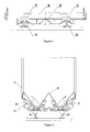
- the hopper car represented on Figures 1 and 2 comprises in a manner known per se a frame 1 carried by two bogies 2 and on which is fixed a hopper 3 open at its upper part. Inside the hopper are arranged two inclined convergent planes 4 in the direction of the unloading hatches 5 arranged under the chassis between the bogies.
- a measuring frame 6 is movably mounted relative to the frame by hydraulic cylinders 7, the maneuver allows to lower and raise the metering frame between its transport and working positions.
- hydraulic locking means and mechanical locking of the measuring frame 6 in the transport position.
- These hydraulic locking means are constituted by the pistons 8 carried by the frame of the wagon and whose free end of the rod can be engaged in or released from a strike 9 carried by an end span of the metering frame.
- the mechanical locking means are constituted by two L-shaped rods 10 whose nose is adapted to cooperate with a shoulder of a longitudinal member of the wagon frame and whose tail, articulated on an end span of the metering frame, is connected by rods 11 to a control rod 12.
- the hydraulic lock makes it possible to quickly ensure the frame in the up position if necessary during the maneuvers on the site of unloading, while the mechanical lock is intended for the permanent maintenance of the metering frame in high position during transport.
- this high position is located above the low rail gauge symbolized by line G.
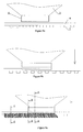
- the metering frame 6 essentially consists of two side members 13 joined at their ends by two bays 14. It forms an enclosure surrounding the unloading hatches 5 at the bottom of the hopper 3.
- the bays 14 carry two rail protectors 15 , in the form of flared skirts, so as to cover the rails and their attachment systems to avoid depositing ballast during unloading operations.
- the spans 14 also carry at least one, and in this example of embodiment two domes 16 fixed on a beam 17 and whose function is, in combination with the rail protectors 15, to ensure the dosing of the amount of ballast deposited on the track during the unloading operations.
- the rail protectors 15 are provided with sliding pads 18 which are intended to come into contact with the mushrooms of the rails when the metering frame is lowered into the working position and make it possible to guide the frame along the rails without risk. damage to these.
- the pads 18 may be replaced by rollers, rollers or any other device capable of facilitating the sliding of the frame on the rails.
- the rail protectors are so wide that they allow a passage in the curves of a minimum radius of 50 meters.
- the lower shape of the spans 14 reproduces the desired profile of the ballast on the track after unloading and thus fulfills a pre-leveling function which eliminates the necessary rework operations with the hopper cars of the prior art. More precisely, the sides of the lower part of the spans form notches with respect to the central part, because the ballast must be deposited on the sides of the track at a greater thickness than between the rails (see Figures 9d to 9f ).
- the bottom of the hopper 3 is equipped with four hatches 5 arranged on either side of a distribution dome 19 disposed along the longitudinal longitudinal axis 20 of the wagon.
- the chassis of the wagon comprises two domes 21 which define the four passages controlled by the hatches. 5, namely two lateral passages and two central passages.
- the hatches 5 are articulated and controlled individually by the hydraulic cylinders 22 visible on the figures 6 and 8 . This arrangement allows a controlled discharge of the ballast on the side of the rails and / or simultaneously or separately between the rails, in any combination suitable for the work to be performed.
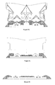
- FIGs 9a to 9f schematically illustrate the progress of a ballast unloading site by means of a train consisting of hopper cars according to the invention.
- the car On the figure 9a the car is positioned on the portion of track to be treated, which has been previously cleared. R rails and T cross members are empty of ballast.
- the cylinders 7 After unlocking the hydraulic and mechanical locking devices of the metering frame 6, the latter is lowered by controlled gravity using the cylinders 7 ( figure 9b ) to come to rest on the tracks of the track by the pads 18 of the rail protectors 15.
- the hatches 5 are open and the ballast is discharged by gravity inside the metering frame 6 ( Figures 9c and 9d ), while the simultaneous advance of the wagon ensures a pre leveling of the ballast unloaded by the special configuration of the spans of the metering frame 6 ( figure 9e ). After the passage of the wagon, the ballast was regularly distributed between the rails and on the sides thereof, without spreading on the rails and their fasteners ( figure 9f ).
- the quantity of unloaded ballast is automatically regulated by the metering frame, even in the case of untimely stop of the train.
- the hatches are radiocontrolled. It is then possible to considerably reduce the number of operators necessary for the unloading operation. Indeed, by the conjunction of the absence of dust release and self-regulation resulting from the use of the metering frame combined with the individual hydraulic control of the traps, a single operator walking on each side of the train along the track sufficient to exercise effective visual control of the unloading of the ballast and to order instantly closing the traps located on its side when needed.
Abstract
Description
L'invention concerne le déchargement de ballast sur une voie ferrée. Actuellement, cette opération s'effectue généralement en mettant en oeuvre des trains de wagons trémie équipés de portes permettant un déversement central et/ou un déversement latéral de part et d'autre du wagon. Typiquement un train de ballastage est constitué de 20 wagons ayant une contenance unitaire de l'ordre de 40 à 50 m3 de ballast. Un train de ballast est tracté par plusieurs motrices de forte puissance (de l'ordre de 2000 CV chacune) qui doivent assurer la traction de cette rame sur le chantier de ballastage à faible vitesse de l'ordre de 4 à 5 km/h. Sur le chantier, l'opération de ballastage requiert un personnel nombreux, soit deux opérateurs par wagon (un pour chaque partie latérale du wagon) complétés par un ou plusieurs opérateurs qui, marchant le long de la voie, surveillent le déchargement du ballast et signalent tout incident éventuel, les autres, se tenant sur la plate-forme du wagon, prêts à manoeuvrer les commandes des portes en fonction des ordres qu'il reçoivent de leurs équipiers marchant le long de la voie. D'autre part, les ouvertures des portes de déversement des wagons se trouvent habituellement à une hauteur d'environ 700 mm au-dessus du plancher de la voie.The invention relates to the unloading of ballast on a railway track. Currently, this operation is generally carried out by implementing hopper car trains equipped with doors allowing a central spill and / or lateral spill on either side of the wagon. Typically a ballast train consists of 20 wagons having a unit capacity of about 40 to 50 m3 of ballast. A ballast train is towed by several power vehicles (of the order of 2000 HP each) which must ensure the traction of this train on the ballast site at low speed of the order of 4 to 5 km / h. On site, the ballast operation requires a large staff, two operators per wagon (one for each side of the wagon) completed by one or more operators who, walking along the track, monitor the unloading of the ballast and report any incident, the others, standing on the platform of the wagon, ready to maneuver the controls of the doors according to the orders that they receive from their crews walking along the way. On the other hand, the openings of the cars spill doors are usually at a height of about 700 mm above the floor of the track.
Les principaux inconvénients constatés lors des opérations de ballastage avec les matériels connus sont les suivants :
- impossibilité de déverser, simultanément le ballast entre les rails et sur les cotés de la voie par les ouvertures de déversement dont le positionnement doit être prédisposé,
- bruit et poussière importants du fait de la grande hauteur de chute,
- imprécision de la dépose et nécessité de procéder à des opérations de reprise et de nivellement complémentaires,
- risque d'accumulation de ballast sur les rails de la voie en travaux entraînant un risque de déraillement sur cette voie et de projection de ballast sur la voie adjacente, entraînant un risque pour les trains circulant sur ces voies ou pour le personnel travaillant à proximité.
- impossibility of discharging, at the same time, the ballast between the rails and on the sides of the track by the spill openings whose positioning must be predisposed,
- significant noise and dust due to the high drop height,
- imprecision of removal and need for additional recovery and leveling operations,
- there is a risk of ballast build-up on the track rails in the works leading to a risk of derailment on this track and ballast projection on the adjacent track, resulting in a risk for trains running on these tracks or for personnel working nearby.
La présente invention vise à remédier à ces inconvénients en procurant un wagon trémie équipé de moyens permettant de déverser simultanément le ballast sur toute la largeur de l'assise de la voie, en réduisant considérablement les bruits et les émissions de poussières, en assurant une dépose homogène et précise du ballast et en éliminant tout risque de projection ou d'accumulation intempestive du ballast hors de la zone de travail, même en cas d'arrêt intempestif de la traction du train de déchargement.The present invention aims to overcome these disadvantages by providing a hopper car equipped with means for discharging simultaneously the ballast across the width of the seat of the track, significantly reducing noise and dust emissions, ensuring removal homogeneous and accurate ballast and eliminating any risk of inadvertent spraying or accumulation of ballast out of the work area, even in the event of an untimely stop of the traction of the unloading train.
Selon l'invention, le wagon trémie, qui comporte en partie basse un cadre doseur mobile entre une position de transport dans laquelle son plan de délimitation inférieur se trouve au-dessus de la hauteur minimale de consigne et une position de travail dans laquelle il affleure le plancher de la voie et forme une enceinte close autour des portes de déversement, ledit cadre étant muni de moyens lui permettant de venir en appui coulissant sur les rails de la voie en position basse et de moyens assurant un pré nivellement du ballast, est caractérisé en ce que ledit cadre doseur est équipé de moyens de verrouillage hydraulique et de verrouillage mécanique par rapport au châssis du wagon.According to the invention, the hopper car, which comprises at the bottom a mobile measuring frame between a transport position in which its lower delimiting plane is above the minimum setpoint height and a working position in which it outcrops. the floor of the track and forms a closed enclosure around the spill doors, said frame being provided with means enabling it to come into sliding support on the tracks of the track in the low position and means ensuring a pre leveling of the ballast, is characterized in that said metering frame is equipped with hydraulic locking means and mechanical locking relative to the frame of the wagon.
Grâce à ces dispositions, on confine le déversement du ballast à la zone précise sur laquelle son épandage est désiré, on limite considérablement sa hauteur de chute et par conséquent les nuisances sonores, on évite le dégagement de poussières et la projection de ballast sur les voies adjacentes, on limite le déversement du surplus de ballast lors des arrêts du train de travaux, on supprime les opérations de reprise après le passage du train de travaux, et l'on assure grâce aux moyens de verrouillage mécanique un verrouillage permanent du cadre au châssis pendant le transport tandis que grâce aux moyens de verrouillage hydraulique on peut obtenir un maintien momentané du cadre en position relevée en cas de besoin au cours des phases de travail.Thanks to these arrangements, the dumping of the ballast is confined to the precise zone on which its spreading is desired, its height of fall is considerably limited and consequently the noise nuisance, the Dust generation and the ballast projection on the adjacent lanes, the discharge of surplus ballast is limited during the stops of the train of work, the operations of recovery are suppressed after the passage of the work train, and one ensures thanks to mechanical locking means a permanent locking of the frame to the chassis during transport while thanks to the hydraulic locking means can be obtained a momentary maintenance of the frame in the raised position in case of need during the work phases.
Selon un mode de réalisation préféré, le cadre doseur est constitué par deux longerons dont le bord inférieur est rectiligne et deux travées d'extrémité dont le bord inférieur reproduit le profil du ballast à obtenir.According to a preferred embodiment, the metering frame consists of two longitudinal members whose lower edge is rectilinear and two end bays whose lower edge reproduces the profile of the ballast to obtain.
Selon d'autres caractéristiques préférées :
- le cadre doseur est équipé de deux protecteurs de rails,
- les protecteurs de rails sont munis de patins de glissement ou de rouleaux,
- les protecteurs de rails sont d'une largeur telle qu'ils recouvrent les attaches rails / traverses,
- les protecteurs de rails sont d'une largeur telle qu'ils permettent un passage dans les courbes d'un rayon minimal de 50 mètres,
- le cadre doseur comporte entre les protecteurs de rails au moins un dôme destiné à limiter le flux de ballast,
- le cadre doseur est monté sur le châssis du wagon par des vérins hydrauliques,
- le cadre doseur est équipé de moyens de verrouillage hydraulique et de moyens de verrouillage mécanique par rapport au châssis du wagon,
- le bas de trémie du wagon est équipé de quatre rangées de trappes longitudinales articulées à commandes individuelles hydrauliques,
- les mouvements des trappes et du cadre doseur sont radiocommandés.
- the dosing frame is equipped with two rail protectors,
- the rail guards are provided with sliding pads or rollers,
- the rails protectors are of a width such that they cover the rails / cross ties,
- the rails protectors are of a width such that they allow a passage in the curves of a minimum radius of 50 meters,
- the metering frame comprises between the rail protectors at least one dome intended to limit the flow of ballast,
- the metering frame is mounted on the frame of the wagon by hydraulic cylinders,
- the metering frame is equipped with hydraulic locking means and mechanical locking means relative to the frame of the wagon,
- the hopper bottom of the wagon is equipped with four rows of articulated longitudinal hatches with hydraulic individual controls,
- the movements of the hatches and the metering frame are radiocontrolled.
D'autres caractéristiques et avantages de l'invention ressortiront de la description qui va suivre d'un exemple de réalisation non limitatif d'un wagon trémie conforme à l'invention en relation avec les dessins annexés dans lesquels :
- la
figure 1 est une vue de coté d'un wagon trémie selon l'invention en position de transport, - la
figure 2 est une vue de coté d'un wagon trémie selon l'invention en position de travail, - la
figure 3 est une vue en coupe schématique de l'agencement du bas de trémie du wagon représenté sur les figures précédentes, - la
figure 4 est une vue de dessus du cadre doseur, - la
figure 5 est une vue en bout du cadre doseur, - la
figure 6 est une vue en coupe selon la ligne A-A de lafigure 1 , - la
figure 7 est une vue en coupe selon la ligne B-B de lafigure 1 , - la
figure 8 est une vue en coupe selon la ligne A-A de lafigure 2 , - les
figures 9a à 9f illustrent les phases de fonctionnement du wagon trémie selon l'invention.
- the
figure 1 is a side view of a hopper car according to the invention in transport position, - the
figure 2 is a side view of a hopper car according to the invention in working position, - the
figure 3 is a schematic sectional view of the arrangement of the bottom of the wagon hopper shown in the preceding figures, - the
figure 4 is a top view of the measuring frame, - the
figure 5 is an end view of the measuring frame, - the
figure 6 is a sectional view along line AA of thefigure 1 , - the
figure 7 is a sectional view along line BB of thefigure 1 , - the
figure 8 is a sectional view along line AA of thefigure 2 , - the
Figures 9a to 9f illustrate the phases of operation of the hopper car according to the invention.
Le wagon trémie représenté sur les
On voit plus en détail sur la
Sur la vue de dessus de la
Sur la vue en bout de la
Sur la vue schématique de la
Les
La quantité de ballast déchargée est automatiquement régulée par le cadre doseur, même dans le cas d'arrêt intempestif du train.The quantity of unloaded ballast is automatically regulated by the metering frame, even in the case of untimely stop of the train.
Selon un mode de réalisation préférentiel de l'invention, les trappes sont radiocommandées. Il est alors possible de diminuer considérablement le nombre d'opérateurs nécessaires à l'opération de déchargement. En effet, par la conjonction de l'absence de dégagement de poussières et de l'autorégulation résultant de l'emploi du cadre doseur combinés à la commande hydraulique individuelle des trappes, un seul opérateur marchant de chaque coté du train le long de la voie suffit à exercer un contrôle visuel efficace du déchargement du ballast et à commander instantanément la fermeture des trappes situées de son coté en cas de besoin.According to a preferred embodiment of the invention, the hatches are radiocontrolled. It is then possible to considerably reduce the number of operators necessary for the unloading operation. Indeed, by the conjunction of the absence of dust release and self-regulation resulting from the use of the metering frame combined with the individual hydraulic control of the traps, a single operator walking on each side of the train along the track sufficient to exercise effective visual control of the unloading of the ballast and to order instantly closing the traps located on its side when needed.
Claims (6)
Applications Claiming Priority (1)
| Application Number | Priority Date | Filing Date | Title |
|---|---|---|---|
| FR0700874A FR2912158B1 (en) | 2007-02-07 | 2007-02-07 | WAGON FOR DISCHARGING BALLAST ON A RAILWAY |
Publications (1)
| Publication Number | Publication Date |
|---|---|
| EP1956144A1 true EP1956144A1 (en) | 2008-08-13 |
Family
ID=38463772
Family Applications (1)
| Application Number | Title | Priority Date | Filing Date |
|---|---|---|---|
| EP08290103A Withdrawn EP1956144A1 (en) | 2007-02-07 | 2008-02-04 | Wagon for unloading ballast on a railway |
Country Status (2)
| Country | Link |
|---|---|
| EP (1) | EP1956144A1 (en) |
| FR (1) | FR2912158B1 (en) |
Cited By (4)
| Publication number | Priority date | Publication date | Assignee | Title |
|---|---|---|---|---|
| CN101746383A (en) * | 2008-12-18 | 2010-06-23 | 南车长江车辆有限公司 | Ballast discharging door device of railway ballast vehicle |
| FR3008110A1 (en) * | 2013-07-05 | 2015-01-09 | Forges Et Const Metalliques Friederich | RAILWAY BALLAST, DEVICE AND METHOD FOR PRODUCING SUCH A RAILWAY BALLAST |
| CN104325985A (en) * | 2014-10-15 | 2015-02-04 | 南车眉山车辆有限公司 | Bidirectional automatic unloading hopper car |
| CN108978370A (en) * | 2018-09-14 | 2018-12-11 | 中国铁建高新装备股份有限公司 | A kind of lower tiny fragments of stone, coal, etc. device for the backfill of pick nest |
Families Citing this family (3)
| Publication number | Priority date | Publication date | Assignee | Title |
|---|---|---|---|---|
| CN102535270B (en) * | 2011-10-13 | 2014-08-27 | 中铁十四局集团有限公司 | Ballast paver |
| FR3085931B1 (en) | 2018-09-14 | 2020-11-06 | Rolanfer Materiel Ferroviaire | BALLAST UNLOADING DEVICE, AND BALLASTAGE RAILWAY WAGON EQUIPPED WITH SUCH A DEVICE |
| RU2769590C1 (en) * | 2021-06-08 | 2022-04-04 | Общество с ограниченной ответственностью Вагонпутьмашпроект | Method for controlling the dosing of bulk cargo, mainly ballast, on a railway track from special rolling stock with the known stiffness of spring suspension and a system for its implementation |
Citations (6)
| Publication number | Priority date | Publication date | Assignee | Title |
|---|---|---|---|---|
| US1743579A (en) * | 1927-08-06 | 1930-01-14 | Automatic Ballast Spreader Cor | Means for discharging ballast |
| US2961975A (en) * | 1957-06-20 | 1960-11-29 | George W Hunt | Ballast applicator and distributor |
| CH408085A (en) * | 1962-02-12 | 1966-02-28 | Reichsbahn Der Generaldirektor | Device for distributing track ballast |
| FR2291932A1 (en) * | 1974-11-23 | 1976-06-18 | Chorzowska Wytwornia Konstrukc | Equipment for closing off loading opening of container - has two pivoting doors positioned below flow dividing triangular beam |
| EP0915203A1 (en) * | 1997-11-05 | 1999-05-12 | Franz Plasser Bahnbaumaschinen-Industriegesellschaft m.b.H. | Ballast leveling machine and method for placing the ballast of a railway track |
| RU2180888C1 (en) * | 2000-09-29 | 2002-03-27 | Общество с ограниченной ответственностью "Вагонпутьмашпроект" | Hopper-batcher |
-
2007
- 2007-02-07 FR FR0700874A patent/FR2912158B1/en active Active
-
2008
- 2008-02-04 EP EP08290103A patent/EP1956144A1/en not_active Withdrawn
Patent Citations (6)
| Publication number | Priority date | Publication date | Assignee | Title |
|---|---|---|---|---|
| US1743579A (en) * | 1927-08-06 | 1930-01-14 | Automatic Ballast Spreader Cor | Means for discharging ballast |
| US2961975A (en) * | 1957-06-20 | 1960-11-29 | George W Hunt | Ballast applicator and distributor |
| CH408085A (en) * | 1962-02-12 | 1966-02-28 | Reichsbahn Der Generaldirektor | Device for distributing track ballast |
| FR2291932A1 (en) * | 1974-11-23 | 1976-06-18 | Chorzowska Wytwornia Konstrukc | Equipment for closing off loading opening of container - has two pivoting doors positioned below flow dividing triangular beam |
| EP0915203A1 (en) * | 1997-11-05 | 1999-05-12 | Franz Plasser Bahnbaumaschinen-Industriegesellschaft m.b.H. | Ballast leveling machine and method for placing the ballast of a railway track |
| RU2180888C1 (en) * | 2000-09-29 | 2002-03-27 | Общество с ограниченной ответственностью "Вагонпутьмашпроект" | Hopper-batcher |
Cited By (5)
| Publication number | Priority date | Publication date | Assignee | Title |
|---|---|---|---|---|
| CN101746383A (en) * | 2008-12-18 | 2010-06-23 | 南车长江车辆有限公司 | Ballast discharging door device of railway ballast vehicle |
| FR3008110A1 (en) * | 2013-07-05 | 2015-01-09 | Forges Et Const Metalliques Friederich | RAILWAY BALLAST, DEVICE AND METHOD FOR PRODUCING SUCH A RAILWAY BALLAST |
| CN104325985A (en) * | 2014-10-15 | 2015-02-04 | 南车眉山车辆有限公司 | Bidirectional automatic unloading hopper car |
| CN108978370A (en) * | 2018-09-14 | 2018-12-11 | 中国铁建高新装备股份有限公司 | A kind of lower tiny fragments of stone, coal, etc. device for the backfill of pick nest |
| CN108978370B (en) * | 2018-09-14 | 2023-11-07 | 中国铁建高新装备股份有限公司 | Ballasting device for backfilling pick sockets |
Also Published As
| Publication number | Publication date |
|---|---|
| FR2912158B1 (en) | 2009-07-03 |
| FR2912158A1 (en) | 2008-08-08 |
Similar Documents
| Publication | Publication Date | Title |
|---|---|---|
| EP1956144A1 (en) | Wagon for unloading ballast on a railway | |
| CH620005A5 (en) | ||
| DE3711707A1 (en) | TRACKABLE DUMP CARGO LOADER WITH CONTROLLED UNLOADING CHEESES | |
| DE19623940B4 (en) | Storage trolleys for storing bulk goods | |
| FR2532968A1 (en) | TOOL ARRANGEMENT FOR BOTTOM UNDER BOTTOM, LEVELING AND LATERAL DRESSING OF A RAILWAY | |
| US20170042137A1 (en) | System and method for mobile subvehicular access and treatment of ground surfaces about occupied rail tracks | |
| FR2690700A1 (en) | Installation for the continuous sanitation of a ballast bed of a railway. | |
| FR2659990A1 (en) | BALLAST BED DISTRIBUTION AND LEVELING MACHINE. | |
| EP0108168B1 (en) | Track installation replacement method and train for carrying out the method | |
| US5437232A (en) | Ballast plow assembly for a hopper-type railroad car | |
| FR2972378A1 (en) | Light shelter useful for welding of rail, comprises a roof, a partition, a fixing unit placed at the rail to be welded and/or adjacent to the rail to be welded, and a light structure that is demountable and/or hingedly supports fabric | |
| FR2988737A1 (en) | DOUBLE FLOW BALLASTAGE TRAIN. | |
| FR2972755A1 (en) | Secure access device for providing access to cistern towed by vehicle, has footbridge secured to actuating units actuated from ground for folding up and folding back footbridge on container or deploying footbridge to project from container | |
| FR2777024A1 (en) | MACHINE COMPRISING A DEVICE FOR CLEANING CROSS-CROSS BOXES | |
| EP0775780B1 (en) | Method for renewing railway tracks | |
| CA2858502A1 (en) | Rail-pushing car | |
| FR2735505A1 (en) | RAILWAY CONSTRUCTION VEHICLE AND ARRANGEMENT OF MACHINES FOR PERFORMING WORK ON THE TRACK CONTAINING THIS VEHICLE | |
| FR2531732A1 (en) | Road gravel and sand spreading device for superficial coatings. | |
| FR2736367A1 (en) | Installation for continuous repair of rail track - comprises several pivoted machine chassis, supported on wheels, having systems for placing new sleepers, lifting old sleepers from track and ballast cleaning and ejection | |
| EP3623245B1 (en) | Device for unloading ballast, and railway vehicle for ballasting equipped with such a device | |
| FR2849069A1 (en) | Protection guard for railway maintenance has trolley with bogies and pivoted detachable protection grill or barrier | |
| DE605187C (en) | Mobile depositing device intended for tipping up and down goods | |
| US3112711A (en) | Railroad car replacer | |
| CH309855A (en) | Screen wagon for the continuous purification of railroad ballast. | |
| DE227252C (en) |
Legal Events
| Date | Code | Title | Description |
|---|---|---|---|
| PUAI | Public reference made under article 153(3) epc to a published international application that has entered the european phase |
Free format text: ORIGINAL CODE: 0009012 |
|
| AK | Designated contracting states |
Kind code of ref document: A1 Designated state(s): AT BE BG CH CY CZ DE DK EE ES FI FR GB GR HR HU IE IS IT LI LT LU LV MC MT NL NO PL PT RO SE SI SK TR |
|
| AX | Request for extension of the european patent |
Extension state: AL BA MK RS |
|
| 17P | Request for examination filed |
Effective date: 20090204 |
|
| 17Q | First examination report despatched |
Effective date: 20090311 |
|
| AKX | Designation fees paid |
Designated state(s): AT BE BG CH CY CZ DE DK EE ES FI FR GB GR HR HU IE IS IT LI LT LU LV MC MT NL NO PL PT RO SE SI SK TR |
|
| STAA | Information on the status of an ep patent application or granted ep patent |
Free format text: STATUS: THE APPLICATION IS DEEMED TO BE WITHDRAWN |
|
| 18D | Application deemed to be withdrawn |
Effective date: 20111112 |