EP1955807A1 - Linearmodul mit Spindeltriebvorrichtung - Google Patents
Linearmodul mit Spindeltriebvorrichtung Download PDFInfo
- Publication number
- EP1955807A1 EP1955807A1 EP20080002016 EP08002016A EP1955807A1 EP 1955807 A1 EP1955807 A1 EP 1955807A1 EP 20080002016 EP20080002016 EP 20080002016 EP 08002016 A EP08002016 A EP 08002016A EP 1955807 A1 EP1955807 A1 EP 1955807A1
- Authority
- EP
- European Patent Office
- Prior art keywords
- table part
- linear module
- module according
- base plate
- web
- Prior art date
- Legal status (The legal status is an assumption and is not a legal conclusion. Google has not performed a legal analysis and makes no representation as to the accuracy of the status listed.)
- Granted
Links
- 229910052782 aluminium Inorganic materials 0.000 claims description 4
- XAGFODPZIPBFFR-UHFFFAOYSA-N aluminium Chemical compound [Al] XAGFODPZIPBFFR-UHFFFAOYSA-N 0.000 claims description 4
- 229910052751 metal Inorganic materials 0.000 claims description 3
- 239000002184 metal Substances 0.000 claims description 3
- 229910001092 metal group alloy Inorganic materials 0.000 claims description 2
- 238000005452 bending Methods 0.000 description 7
- 238000004519 manufacturing process Methods 0.000 description 3
- 238000001125 extrusion Methods 0.000 description 2
- 238000003801 milling Methods 0.000 description 2
- 230000035515 penetration Effects 0.000 description 2
- 230000005540 biological transmission Effects 0.000 description 1
- 238000010276 construction Methods 0.000 description 1
- 230000000694 effects Effects 0.000 description 1
- 239000004519 grease Substances 0.000 description 1
- 238000009434 installation Methods 0.000 description 1
- 239000000314 lubricant Substances 0.000 description 1
- 238000005461 lubrication Methods 0.000 description 1
- 238000007789 sealing Methods 0.000 description 1
- 230000000007 visual effect Effects 0.000 description 1
Images


Classifications
-
- B—PERFORMING OPERATIONS; TRANSPORTING
- B23—MACHINE TOOLS; METAL-WORKING NOT OTHERWISE PROVIDED FOR
- B23Q—DETAILS, COMPONENTS, OR ACCESSORIES FOR MACHINE TOOLS, e.g. ARRANGEMENTS FOR COPYING OR CONTROLLING; MACHINE TOOLS IN GENERAL CHARACTERISED BY THE CONSTRUCTION OF PARTICULAR DETAILS OR COMPONENTS; COMBINATIONS OR ASSOCIATIONS OF METAL-WORKING MACHINES, NOT DIRECTED TO A PARTICULAR RESULT
- B23Q5/00—Driving or feeding mechanisms; Control arrangements therefor
- B23Q5/22—Feeding members carrying tools or work
- B23Q5/34—Feeding other members supporting tools or work, e.g. saddles, tool-slides, through mechanical transmission
- B23Q5/38—Feeding other members supporting tools or work, e.g. saddles, tool-slides, through mechanical transmission feeding continuously
- B23Q5/40—Feeding other members supporting tools or work, e.g. saddles, tool-slides, through mechanical transmission feeding continuously by feed shaft, e.g. lead screw
-
- B—PERFORMING OPERATIONS; TRANSPORTING
- B23—MACHINE TOOLS; METAL-WORKING NOT OTHERWISE PROVIDED FOR
- B23Q—DETAILS, COMPONENTS, OR ACCESSORIES FOR MACHINE TOOLS, e.g. ARRANGEMENTS FOR COPYING OR CONTROLLING; MACHINE TOOLS IN GENERAL CHARACTERISED BY THE CONSTRUCTION OF PARTICULAR DETAILS OR COMPONENTS; COMBINATIONS OR ASSOCIATIONS OF METAL-WORKING MACHINES, NOT DIRECTED TO A PARTICULAR RESULT
- B23Q11/00—Accessories fitted to machine tools for keeping tools or parts of the machine in good working condition or for cooling work; Safety devices specially combined with or arranged in, or specially adapted for use in connection with, machine tools
- B23Q11/08—Protective coverings for parts of machine tools; Splash guards
- B23Q11/0825—Relatively slidable coverings, e.g. telescopic
-
- F—MECHANICAL ENGINEERING; LIGHTING; HEATING; WEAPONS; BLASTING
- F16—ENGINEERING ELEMENTS AND UNITS; GENERAL MEASURES FOR PRODUCING AND MAINTAINING EFFECTIVE FUNCTIONING OF MACHINES OR INSTALLATIONS; THERMAL INSULATION IN GENERAL
- F16C—SHAFTS; FLEXIBLE SHAFTS; ELEMENTS OR CRANKSHAFT MECHANISMS; ROTARY BODIES OTHER THAN GEARING ELEMENTS; BEARINGS
- F16C29/00—Bearings for parts moving only linearly
-
- F—MECHANICAL ENGINEERING; LIGHTING; HEATING; WEAPONS; BLASTING
- F16—ENGINEERING ELEMENTS AND UNITS; GENERAL MEASURES FOR PRODUCING AND MAINTAINING EFFECTIVE FUNCTIONING OF MACHINES OR INSTALLATIONS; THERMAL INSULATION IN GENERAL
- F16C—SHAFTS; FLEXIBLE SHAFTS; ELEMENTS OR CRANKSHAFT MECHANISMS; ROTARY BODIES OTHER THAN GEARING ELEMENTS; BEARINGS
- F16C29/00—Bearings for parts moving only linearly
- F16C29/004—Fixing of a carriage or rail, e.g. rigid mounting to a support structure or a movable part
-
- F—MECHANICAL ENGINEERING; LIGHTING; HEATING; WEAPONS; BLASTING
- F16—ENGINEERING ELEMENTS AND UNITS; GENERAL MEASURES FOR PRODUCING AND MAINTAINING EFFECTIVE FUNCTIONING OF MACHINES OR INSTALLATIONS; THERMAL INSULATION IN GENERAL
- F16C—SHAFTS; FLEXIBLE SHAFTS; ELEMENTS OR CRANKSHAFT MECHANISMS; ROTARY BODIES OTHER THAN GEARING ELEMENTS; BEARINGS
- F16C29/00—Bearings for parts moving only linearly
- F16C29/04—Ball or roller bearings
- F16C29/06—Ball or roller bearings in which the rolling bodies circulate partly without carrying load
- F16C29/0602—Details of the bearing body or carriage or parts thereof, e.g. methods for manufacturing or assembly
-
- F—MECHANICAL ENGINEERING; LIGHTING; HEATING; WEAPONS; BLASTING
- F16—ENGINEERING ELEMENTS AND UNITS; GENERAL MEASURES FOR PRODUCING AND MAINTAINING EFFECTIVE FUNCTIONING OF MACHINES OR INSTALLATIONS; THERMAL INSULATION IN GENERAL
- F16C—SHAFTS; FLEXIBLE SHAFTS; ELEMENTS OR CRANKSHAFT MECHANISMS; ROTARY BODIES OTHER THAN GEARING ELEMENTS; BEARINGS
- F16C2322/00—Apparatus used in shaping articles
- F16C2322/39—General buildup of machine tools, e.g. spindles, slides, actuators
-
- F—MECHANICAL ENGINEERING; LIGHTING; HEATING; WEAPONS; BLASTING
- F16—ENGINEERING ELEMENTS AND UNITS; GENERAL MEASURES FOR PRODUCING AND MAINTAINING EFFECTIVE FUNCTIONING OF MACHINES OR INSTALLATIONS; THERMAL INSULATION IN GENERAL
- F16C—SHAFTS; FLEXIBLE SHAFTS; ELEMENTS OR CRANKSHAFT MECHANISMS; ROTARY BODIES OTHER THAN GEARING ELEMENTS; BEARINGS
- F16C29/00—Bearings for parts moving only linearly
- F16C29/04—Ball or roller bearings
- F16C29/06—Ball or roller bearings in which the rolling bodies circulate partly without carrying load
- F16C29/0633—Ball or roller bearings in which the rolling bodies circulate partly without carrying load with a bearing body defining a U-shaped carriage, i.e. surrounding a guide rail or track on three sides
- F16C29/0635—Ball or roller bearings in which the rolling bodies circulate partly without carrying load with a bearing body defining a U-shaped carriage, i.e. surrounding a guide rail or track on three sides whereby the return paths are provided as bores in a main body of the U-shaped carriage, e.g. the main body of the U-shaped carriage is a single part with end caps provided at each end
- F16C29/0638—Ball or roller bearings in which the rolling bodies circulate partly without carrying load with a bearing body defining a U-shaped carriage, i.e. surrounding a guide rail or track on three sides whereby the return paths are provided as bores in a main body of the U-shaped carriage, e.g. the main body of the U-shaped carriage is a single part with end caps provided at each end with balls
- F16C29/0642—Ball or roller bearings in which the rolling bodies circulate partly without carrying load with a bearing body defining a U-shaped carriage, i.e. surrounding a guide rail or track on three sides whereby the return paths are provided as bores in a main body of the U-shaped carriage, e.g. the main body of the U-shaped carriage is a single part with end caps provided at each end with balls with four rows of balls
- F16C29/0645—Ball or roller bearings in which the rolling bodies circulate partly without carrying load with a bearing body defining a U-shaped carriage, i.e. surrounding a guide rail or track on three sides whereby the return paths are provided as bores in a main body of the U-shaped carriage, e.g. the main body of the U-shaped carriage is a single part with end caps provided at each end with balls with four rows of balls with load directions in O-arrangement
-
- F—MECHANICAL ENGINEERING; LIGHTING; HEATING; WEAPONS; BLASTING
- F16—ENGINEERING ELEMENTS AND UNITS; GENERAL MEASURES FOR PRODUCING AND MAINTAINING EFFECTIVE FUNCTIONING OF MACHINES OR INSTALLATIONS; THERMAL INSULATION IN GENERAL
- F16H—GEARING
- F16H25/00—Gearings comprising primarily only cams, cam-followers and screw-and-nut mechanisms
- F16H25/18—Gearings comprising primarily only cams, cam-followers and screw-and-nut mechanisms for conveying or interconverting oscillating or reciprocating motions
- F16H25/20—Screw mechanisms
- F16H2025/204—Axial sliding means, i.e. for rotary support and axial guiding of nut or screw shaft
-
- F—MECHANICAL ENGINEERING; LIGHTING; HEATING; WEAPONS; BLASTING
- F16—ENGINEERING ELEMENTS AND UNITS; GENERAL MEASURES FOR PRODUCING AND MAINTAINING EFFECTIVE FUNCTIONING OF MACHINES OR INSTALLATIONS; THERMAL INSULATION IN GENERAL
- F16H—GEARING
- F16H25/00—Gearings comprising primarily only cams, cam-followers and screw-and-nut mechanisms
- F16H25/18—Gearings comprising primarily only cams, cam-followers and screw-and-nut mechanisms for conveying or interconverting oscillating or reciprocating motions
- F16H25/20—Screw mechanisms
-
- Y—GENERAL TAGGING OF NEW TECHNOLOGICAL DEVELOPMENTS; GENERAL TAGGING OF CROSS-SECTIONAL TECHNOLOGIES SPANNING OVER SEVERAL SECTIONS OF THE IPC; TECHNICAL SUBJECTS COVERED BY FORMER USPC CROSS-REFERENCE ART COLLECTIONS [XRACs] AND DIGESTS
- Y10—TECHNICAL SUBJECTS COVERED BY FORMER USPC
- Y10T—TECHNICAL SUBJECTS COVERED BY FORMER US CLASSIFICATION
- Y10T74/00—Machine element or mechanism
- Y10T74/18—Mechanical movements
- Y10T74/18568—Reciprocating or oscillating to or from alternating rotary
- Y10T74/18576—Reciprocating or oscillating to or from alternating rotary including screw and nut
-
- Y—GENERAL TAGGING OF NEW TECHNOLOGICAL DEVELOPMENTS; GENERAL TAGGING OF CROSS-SECTIONAL TECHNOLOGIES SPANNING OVER SEVERAL SECTIONS OF THE IPC; TECHNICAL SUBJECTS COVERED BY FORMER USPC CROSS-REFERENCE ART COLLECTIONS [XRACs] AND DIGESTS
- Y10—TECHNICAL SUBJECTS COVERED BY FORMER USPC
- Y10T—TECHNICAL SUBJECTS COVERED BY FORMER US CLASSIFICATION
- Y10T74/00—Machine element or mechanism
- Y10T74/18—Mechanical movements
- Y10T74/18568—Reciprocating or oscillating to or from alternating rotary
- Y10T74/18576—Reciprocating or oscillating to or from alternating rotary including screw and nut
- Y10T74/18656—Carriage surrounded, guided, and primarily supported by member other than screw [e.g., linear guide, etc.]
-
- Y—GENERAL TAGGING OF NEW TECHNOLOGICAL DEVELOPMENTS; GENERAL TAGGING OF CROSS-SECTIONAL TECHNOLOGIES SPANNING OVER SEVERAL SECTIONS OF THE IPC; TECHNICAL SUBJECTS COVERED BY FORMER USPC CROSS-REFERENCE ART COLLECTIONS [XRACs] AND DIGESTS
- Y10—TECHNICAL SUBJECTS COVERED BY FORMER USPC
- Y10T—TECHNICAL SUBJECTS COVERED BY FORMER US CLASSIFICATION
- Y10T74/00—Machine element or mechanism
- Y10T74/18—Mechanical movements
- Y10T74/18568—Reciprocating or oscillating to or from alternating rotary
- Y10T74/18576—Reciprocating or oscillating to or from alternating rotary including screw and nut
- Y10T74/18672—Plural screws in series [e.g., telescoping, etc.]
Definitions
- the invention relates to a linear module comprising a base plate unit, a table part, a spindle drive device which has a spindle connected in force to a drive unit mounted on the base plate unit and a nut connected to the table part and threadedly engaged with the spindle, and a telescopic tube arrangement surrounding the spindle which has two tubular elements telescoping in a direction of movement, namely a tubular element connected to the base plate unit and a tubular element connected to the table part.
- Such a linear module is for example from the US 5,676,016 known.
- the pipe member connected to the table part is fixed to an end plate, which in turn is connected to the table part.
- a linear module of the type mentioned in which the pipe member connected to the table part is connected to the table part on a portion of its length via at least one web, and connected to the base plate unit tube member at least one for receiving the at least one Has web specific slot.
- the two pipe elements can even be performed together, as applied to the pipe member connected to the pipe member bending moments can not lead as in the prior art to an increase in friction and thus obstruction of the telescopic movement.
- the interior of the telescopic tube assembly can be better protected against the ingress of dirt without additional sealing measures.
- the length of the at least one web can advantageously be at most the same size as that of the slot assigned to this web.
- the length of the at least one slot is dimensioned such that it is still covered by the table part in the extended telescopic state. This in turn has advantages in terms of the penetration of dirt, but also in terms of visual appearance of the overall arrangement.
- the at least one web connects to the end of the tubular element connected to the table part, which end is remote from the drive unit.
- the drive unit closed end of the connected to the table part pipe element by means of a closure element, for example, a, preferably made of plastic, plug is closed.
- a closure element for example, a, preferably made of plastic, plug
- the table part has at least one through-hole which permits access to attachment points of the base plate unit in a state mounted on the base plate unit of the table part. In this way, access to the attachment points is possible, to which the base plate unit to a parent assembly a production line or the like can be attached.
- the pipe element connected to the table part is formed separately from this and screwed to this, this allows a particularly simple production of the linear module.
- the pipe element connected to the table part is integrally formed therewith, which brings with it particular advantages for the stability and thus the reduction of the transmission of bending moments to the pipe element. Since this feature per se is also not known from the prior art, separate protection is sought for this purpose.
- the table part is produced starting from an extruded profile element, which is preferably made of a light metal or a light metal alloy, for example aluminum.
- an extruded profile element which is preferably made of a light metal or a light metal alloy, for example aluminum.
- table part of the web can be obtained in this case, for example by Wegfräsen a part of the at least one connecting bridge of the tubular element with the table part.
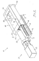
- a linear module according to the invention generally designated 10. It comprises a rail 14 mounted on a base plate 12 and extending in a longitudinal direction X. Furthermore, it comprises a table part 16, which is displaceably guided on the rail 14 in the longitudinal direction X thereof by means of a linear guide device 18. To drive the table part 16 relative to the rail 14 is a spindle drive 20 with a motor 22 driven by a spindle 24 which is in threaded engagement with a nut 26.
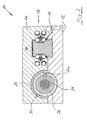
- the spindle 24 and the nut 26 of the spindle drive 20 are, as in particular in Fig. 2 is surrounded by an inner tube member 28 and an outer tube member 30 which telescopically engage with each other.
- the nut 26 is fastened both rotationally and translationally in the inner tubular element 28 via an element 26a.
- the outer tube member 30 is integrally formed with the base plate unit 12, while the inner tube member 28 is associated with the table part 16.
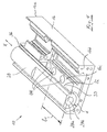
- the table part is made starting from a portion of an extruded profile.
- this extruded profile already integrally formed on the tubular element 28.
- the pipe member 28 is also only connected via a single connecting bridge 32 with the table part 16. In principle, however, several such connection bridges can be provided, as in Fig. 3 indicated by dashed lines at 34.
- a first processing step as in Fig. 4 is shown, the connecting bridge 32 of the in Fig. 4 rear and in Fig. 1 front end face 16a of the table part 16 ago milled away. This milling is in Fig. 4 denoted by 36.
- a second processing step is at the in Fig. 4 front and in Fig. 1 rear end 16b of the table part a piece of the tube member 28, the connecting bridge 32 and this carrying portion 16c of the table part 16 milled away so that the end face 28a of the tube member 28 is set back relative to the end face 16b of the table part 16 by a predetermined distance d slightly. In this way it can be prevented that external forces exerted on an end plate 38 of the table part (see Fig. 1 ) are transferred to the tube element 28.
- the base plate unit 12 starting from an extruded profile, are manufactured, on which the tube member 30 is integrally formed.
- a lateral slot 40 has been introduced into the tube member 30, whose length I 2 is at least the same size as the length I 1 of the web 33.
- the Length I 2 is at least the same size as the length I 1 of the web 33.
- the Length I 2 is at least the same size as the length I 1 of the web 33.
- the Length I 2 by at least the distance d of the reverse milling of the tubular element 28 (see Fig. 4 ) greater than the length I 1 of the web 33.
- Receiving recesses 42 which serve to receive the heads of bolts, by means of which the base plate unit 12 can be attached to a parent assembly.
- 16 through holes 44 are provided in the table part (see also Fig. 4 ), which allow access to the attachment points 42 by means of a fastening tool, such as a screwdriver, a Allen key or the like.
- the lumen 28b of the tubular element 28 can be closed in the region of its end face 28a by means of a plug (not shown).
Landscapes
- Engineering & Computer Science (AREA)
- General Engineering & Computer Science (AREA)
- Mechanical Engineering (AREA)
- Auxiliary Devices For Machine Tools (AREA)
- Bearings For Parts Moving Linearly (AREA)
- Machine Tool Units (AREA)
Abstract
Description
- Die Erfindung betrifft ein Linearmodul umfassend eine Grundplatteneinheit, ein Tischteil, eine Spindeltriebvorrichtung, welche eine mit einer auf der Grundplatteneinheit angebrachten Antriebseinheit in Kraftübertragungsverbindung stehende Spindel und eine mit dem Tischteil verbundene und mit der Spindel im Gewindeeingriff stehende Mutter aufweist, sowie eine die Spindel umgebende Teleskoprohranordnung, welche zwei in einer Bewegungsrichtung teleskopierend ineinander greifende Rohrelemente aufweist, nämlich ein mit der Grundplatteneinheit verbundenes Rohrelement sowie ein mit dem Tischteil verbundenes Rohrelement.
- Ein derartiges Linearmodul ist beispielsweise aus der
US 5,676,016 bekannt. Bei diesem Linearmodul ist das mit dem Tischteil verbundene Rohrelement an einer Endplatte befestigt, welche ihrerseits mit dem Tischteil verbunden ist. Dies hat den Nachteil, dass das mit dem Tischteil verbundene Rohrelement zumindest im verlängerten Teleskopzustand über eine relativ große Länge freitragend angeordnet ist, bevor es mit dem mit der Grundplatteneinheit verbundenem Rohrelement in Teleskopeingriff tritt. Gravierender ist aber, dass jede äußere Kraft, der die Endplatte im Betrieb des Linearmoduls ausgesetzt ist, unweigerlich zu Biegemomenten auf das mit dem Tischteil verbundene Rohrelement führt. Die sich hieraus ergebenden Verformungen behindern aber den Teleskopeingriff der beiden Rohrelemente in Folge erhöhter Reibung, wenn sie nicht gar zu einem Verkanten der beiden Rohre führen. - Demgegenüber ist es Aufgabe der vorliegenden Erfindung, ein Linearmodul der eingangs genannten Art derart auszubilden, dass die auf das mit dem Tischteil verbundene Rohrelement einwirkenden Biegemomente reduziert sind.
- Diese Aufgabe wird erfindungsgemäß durch ein Linearmodul der eingangs genannten Art gelöst, bei welchem das mit dem Tischteil verbundene Rohrelement mit dem Tischteil auf einem Teilabschnitt seiner Länge über wenigstens einen Steg verbunden ist, und das mit der Grundplatteneinheit verbundene Rohrelement wenigstens einen zur Aufnahme des wenigstens einen Stegs bestimmten Schlitz aufweist. Durch den erfindungsgemäß vorgesehenen Steg ist das Rohrelement nicht nur an seinem einen Ende befestigt, wie dies beim Stand der Technik der Fall ist, sondern verfügt über einen Teilabschnitt seiner Länge über eine stabile Verbindung zu dem Tischteil. Daher kann der Steg Biegemomente sehr effektiv von dem Rohrelement fernhalten.
- Hinzu kommt, dass in Folge dieser erhöhten Stabilität gegenüber Biegemomenten die beiden Rohrelemente sogar aneinander geführt sein können, da auf das mit dem Tischteil verbundene Rohrelement ausgeübte Biegemomente nicht wie beim Stand der Technik zu einer Erhöhung der Reibung und somit Behinderung der Teleskopbewegung führen können. Durch dieses enge Aneinanderführen kann der Innenraum der Teleskoprohranordnung auch ohne zusätzliche Abdichtungsmaßnahmen besser vor dem Eindringen von Schmutz geschützt werden. Bei dieser Ausführung kann es sinnvoll sein, eine Gleitbuchse aus Kunststoff zwischen den Metallrohren vorzusehen, so dass unnötiger Verschleiß auf Grund der ungünstigen Gleitpaarung Aluminium/Aluminium vermieden wird.
- Um im verkürzten Teleskopzustand sicherstellen zu können, dass der Steg vollständig im Schlitz aufgenommen werden kann, kann die Länge des wenigstens einen Stegs vorteilhafterweise höchstens gleich groß bemessen sein, wie jene des diesem Steg zugeordneten Schlitzes.
- In Weiterbildung der Erfindung wird vorgeschlagen, dass die Länge des wenigstens einen Schlitzes derart bemessen ist, dass er auch im verlängerten Teleskopzustand noch vom Tischteil bedeckt ist. Dies hat wiederum Vorteile hinsichtlich des Eindringens von Schmutz, aber auch hinsichtlich des optischen Erscheinungsbilds der Gesamtanordnung.
- Um einen möglichst großen Teleskopierweg bereitstellen zu können, kann ferner vorgesehen sein, dass der wenigstens eine Steg an das von der Antriebseinheit entfernte Ende des mit dem Tischteil verbundenen Rohrelements anschließt.
- Um sicherstellen zu können, dass auch bei Ausübung von äußeren Kräften auf das Tischteil, insbesondere auf eine stirnseitig an diesem angebrachte Endplatte, diese sich nur in allenfalls geringem Maße auf das mit dem Tischteil verbundene Rohrelement übertragen können, wird in Weiterbildung der Erfindung vorgeschlagen, dass das von der Antriebseinheit entfernte Ende des mit dem Tischteil verbundenen Rohrelements gegenüber einer ihm benachbarten Stirnfläche des Tischteils in Teleskopierrichtung um einen vorbestimmten Abstand zurücksteht.
- Um in diesem Fall, oder auch dann, wenn an der von der Antriebseinheit entfernten Stirnfläche des Tischteils keine Endplatte vorgesehen ist, das Eindringen von Schmutz in den Innenraum der Teleskoprohranordnung auf herstellungstechnisch einfache Weise verhindern zu können, wird ferner vorgeschlagen, dass das von der Antriebseinheit entfernte Ende des mit dem Tischteil verbundenen Rohrelements mittels eines Verschlusselements, beispielsweise eines, vorzugsweise aus Kunststoff gefertigten, Stopfens, verschlossen ist. Auf diese Weise kann die Teleskopieranordnung auch mit Schmierstoff, beispielsweise Fett gefüllt werden, so dass eine dauerhafte und wartungsfreie Schmierung der Spindel gewährleistet werden kann.
- Um das gesamte Linearmodul vormontiert bereitstellen zu können, wird zudem vorgeschlagen, dass das Tischteil wenigstens ein Durchgangsloch aufweist, welches in einem auf der Grundplatteneinheit montierten Zustand des Tischteils einen Zugriff zu Befestigungsstellen der Grundplatteneinheit gestattet. Auf diese Weise ist ein Zugriff zu den Befestigungsstellen möglich, an welchen die Grundplatteneinheit an einer übergeordneten Baueinheit einer Fertigungsstraße oder dergleichen befestigt werden kann.
- Wenn das mit dem Tischteil verbundene Rohrelement von diesem gesondert ausgebildet und mit diesem verschraubt ist, so ermöglicht dies eine besonders einfache Herstellung des Linearmoduls. Grundsätzlich ist es jedoch auch denkbar, dass das mit dem Tischteil verbundene Rohrelement mit diesem einstückig ausgebildet ist, was besondere Vorteile für die Stabilität und damit die Reduzierung der Übertragung von Biegemomenten auf das Rohrelement mit sich bringt. Da dieses Merkmal für sich genommen aus dem Stand der Technik ebenfalls nicht bekannt ist, wird hierfür gesonderter Schutz angestrebt.
- In jedem Fall ist es jedoch bevorzugt, dass das Tischteil ausgehend von einem Strangpressprofilelement hergestellt ist, welches vorzugsweise aus einem Leichtmetall oder einer Leichtmetalllegierung, beispielsweise Aluminium, gefertigt ist. Bei einstückiger Ausbildung von Steg und Tischteil kann der Steg in diesem Fall beispielsweise durch Wegfräsen eines Teils der wenigstens einen Verbindungsbrücke des Rohrelements mit dem Tischteil erhalten werden.
- Die Erfindung wird im Folgenden an einem Ausführungsbeispiel anhand der beigefügten Zeichnungen näher erläutert werden. Es stellt dar:
- Figur 1
- eine perspektivische Gesamtansicht eines erfindungsgemäßen Linearmoduls;
- Figur 2
- einen in der in
Fig. 1 mit II-II bezeichneten Ebene genommenen Querschnitt des Linearmoduls vonFig. 1 ; - Figuren 3 und 4
- perspektivische Druntersichten des Tischteils des erfindungsgemäßen Linearmoduls, wobei
Fig. 3 den unbearbeiteten Strangpressrohling für das Tischteil undFig. 4 den bearbeiteten Strangpressrohling zeigt; und - Figur 5
- eine perspektivische Draufsicht der Grundplatteneinheit des erfindungsgemäßen Linearmoduls.
- In den
Fig. 1 und2 ist ein erfindungsgemäßes Linearmodul ganz allgemein mit 10 bezeichnet. Es umfasst eine auf einer Grundplatte 12 montierte Schiene 14, die sich einer Längsrichtung X erstreckt. Ferner umfasst sie ein Tischteil 16, welches mittels einer Linearführungsvorrichtung 18 auf der Schiene 14 in deren Längsrichtung X verschiebbar geführt ist. Zum Antrieb des Tischteils 16 relativ zur Schiene 14 dient ein Spindeltrieb 20 mit einer von einem Motor 22 angetriebenen Spindel 24, die mit einer Mutter 26 in Gewindeeingriff steht. - Die Spindel 24 und die Mutter 26 des Spindeltriebs 20 sind, wie insbesondere in
Fig. 2 dargestellt ist, von einem inneren Rohrelement 28 und einem äußeren Rohrelement 30 umgeben, welche teleskopierend ineinander greifen. Dabei ist die Mutter 26 über ein Element 26a sowohl rotatorisch als auch translatorisch in dem inneren Rohrelement 28 befestigt. InFig. 2 erkennt man ferner, dass das äußere Rohrelement 30 mit der Grundplatteneinheit 12 einstückig ausgebildet ist, während das innere Rohrelement 28 dem Tischteil 16 zugeordnet ist. - Nachfolgend soll mit Bezug auf die
Fig. 3 bis 5 der Aufbau und die Herstellung des Tischteils 16 mit dem inneren Rohrelement 28 und der Grundplatteneinheit 12 mit dem äußeren Rohrelement 30 näher erläutert werden: - Wie in
Fig. 3 dargestellt ist, wird das Tischteil ausgehend von einem Abschnitt eines Strangpressprofils hergestellt. In dem dargestellten Ausführungsbeispiel weist dieses Strangpressprofil das Rohrelement 28 bereits einstückig angeformt auf. Grundsätzlich ist es jedoch auch denkbar, das Rohrelement 28 von dem Tischteil 16 gesondert auszubilden und mit diesem beispielsweise durch Verschrauben zu verbinden, wie inFig. 4 durch eine gestrichelte Linie ansatzweise angedeutet ist. In dem inFig. 3 dargestellten Ausführungsbeispiel ist das Rohrelement 28 zudem lediglich über eine einzige Verbindungsbrücke 32 mit dem Tischteil 16 verbunden. Grundsätzlich können aber auch mehrere solche Verbindungsbrücken vorgesehen sein, wie inFig. 3 bei 34 gestrichelt angedeutet ist. - In einem ersten Bearbeitungsschritt wird, wie in
Fig. 4 dargestellt ist, die Verbindungsbrücke 32 von der inFig. 4 hinteren und inFig. 1 vorderen Stirnfläche 16a des Tischteils 16 her weggefräst. Diese Fräsung ist inFig. 4 mit 36 bezeichnet. - In einem zweiten Bearbeitungsschritt wird an dem in
Fig. 4 vorderen und inFig. 1 hinteren Ende 16b des Tischteils ein Stück des Rohrelements 28, der Verbindungsbrücke 32 und des diese tragenden Abschnitts 16c des Tischteils 16 weggefräst, so dass die Stirnfläche 28a des Rohrelements 28 gegenüber der Stirnfläche 16b des Tischteils 16 um einen vorbestimmten Abstand d geringfügig zurückversetzt ist. Auf diese Weise kann verhindert werden, dass äußere Kräfte, die auf eine Endplatte 38 des Tischteils ausgeübt werden (sieheFig. 1 ) auf das Rohrelement 28 übertragen werden. - Nach diesen beiden Bearbeitungsschritten bleibt von der Verbindungsbrücke 32 nur noch ein Steg 33 der Länge I1 übrig.Diese Länge I1 ist aber derart bemessen, dass Biegemomente in Folge äußerer Kräfte sich nicht oder nur in geringem Maße auf das Rohrelement 28 auswirken können.
- Wie in
Fig. 5 dargestellt ist, kann auch die Grundplatteneinheit 12, ausgehend von einem Strangpressprofil, gefertigt werden, an welchem das Rohrelement 30 einstückig angeformt ist. Um im verkürzten Teleskopzustand des Linearmoduls 10 einen Aufnahmeraum für den Steg 33 bereitstellen zu können, ist in das Rohrelement 30 ein seitlicher Schlitz 40 eingebracht worden, dessen Länge I2 mindestens gleich groß bemessen ist wie die Länge I1 des Stegs 33. Vorzugsweise ist die Länge I2 jedoch um mindestens die Distanz d der Rückfräsung des Rohrelements 28 (sieheFig. 4 ) größer bemessen als die Länge I1 des Stegs 33. - Ferner erkennt man in
Fig. 5 Aufnahmevertiefungen 42, die zur Aufnahme der Köpfe von Schraubbolzen dienen, mittels derer die Grundplatteneinheit 12 an einer übergeordneten Baueinheit befestigt werden kann. Um das Linearmodul 10 in dem inFig. 1 dargestellten vormontierten Zustand liefern und gleichwohl die Montage des Linearmoduls 10 an der übergeordneten Baugruppe ermöglichen zu können, sind im Tischteil 16 Durchgangslöcher 44 vorgesehen (siehe auchFig. 4 ), welche einen Zugriff zu den Befestigungsstellen 42 mittels eines Befestigungswerkzeugs, beispielsweise einem Schraubendreher, einem Imbusschlüssel oder dergleichen, ermöglichen. - Nachzutragen ist noch, dass das Lumen 28b des Rohrelements 28 im Bereich von dessen Stirnfläche 28a mittels eines nicht dargestellten Stopfens geschlossen werden kann.
Claims (10)
- Linearmodul (10), umfassend:- eine Grundplatteneinheit (12),- ein Tischteil (16),- eine Spindeltriebvorrichtung (20), welche eine mit einer auf der Grundplatteneinheit (12) angebrachten Antriebseinheit (22) in Kraftübertragungsverbindung stehende Spindel (24) und eine mit dem Tischteil (16) verbundene und mit der Spindel (24) im Gewindeeingriff stehende Mutter (26) aufweist, sowie- eine die Spindel (24) umgebende Teleskoprohranordnung (28/30), welche zwei in einer Bewegungsrichtung teleskopierend ineinander greifende Rohrelemente (28, 30) aufweist, nämlich ein mit der Grundplatteneinheit (12) verbundenes Rohrelement (30) sowie ein mit dem Tischteil (16) verbundenes Rohrelement (28),dadurch gekennzeichnet, dass das mit dem Tischteil (16) verbundene Rohrelement (28) mit dem Tischteil (16) auf einem Teilabschnitt (I1) seiner Länge über wenigstens einen Steg (33) verbunden ist, und dass das mit der Grundplatteneinheit (12) verbundene Rohrelement (30) wenigstens einen zur Aufnahme des wenigstens einen Stegs (33) bestimmten Schlitz (40) aufweist.
- Linearmodul nach Anspruch 1,
dadurch gekennzeichnet, dass die Länge (I1) des wenigstens einen Stegs (33) höchstens gleich groß bemessen ist wie jene (I2) des diesem Steg (33) zugeordneten Schlitzes (40). - Linearmodul nach Anspruch 1 oder 2,
dadurch gekennzeichnet, dass die Länge (I2) des wenigstens einen Schlitzes (40) derart bemessen ist, dass er auch im verlängerten Teleskopzustand noch vom Tischteil (16) bedeckt ist. - Linearmodul nach einem der Ansprüche 1 bis 3,
dadurch gekennzeichnet, dass der wenigstens eine Steg (33) an das von der Antriebseinheit (22) entfernte Ende des mit dem Tischteil (16) verbundenen Rohrelements (28) anschließt. - Linearmodul nach einem der Ansprüche 1 bis 4,
dadurch gekennzeichnet, dass das von der Antriebseinheit (22) entfernte Ende des mit dem Tischteil (16) verbundenen Rohrelements (28) gegenüber einer ihm benachbarten Stirnfläche (16b) des Tischteils (16) in Teleskoprichtung zurücksteht. - Linearmodul nach einem der Ansprüche 1 bis 5,
dadurch gekennzeichnet, dass das von der Antriebseinheit (22) entfernte Ende des mit dem Tischteil (16) verbundenen Rohrelements (28) mittels eines Verschlusselements, beispielsweise eines vorzugsweise aus Kunststoff gefertigten Stopfens, verschlossen ist. - Linearmodul nach einem der Ansprüche 1 bis 6,
dadurch gekennzeichnet, dass das Tischteil wenigstens ein Durchgangsloch (44) aufweist, welches in einem auf der Grundplatteneinheit (12) montierten Zustand des Tischteils (16) einen Zugriff zu Befestigungsstellen (42) der Grundplatteneinheit (12) gestattet. - Linearmodul nach einem der Ansprüche 1 bis 7,
dadurch gekennzeichnet, dass das mit dem Tischteil (16) verbundene Rohrelement (28) mit diesem verschraubt ist. - Linearmodul nach dem Oberbegriff des Anspruchs 1 und gewünschtenfalls dem Kennzeichen eines der Ansprüche 1 bis 7,
dadurch gekennzeichnet, dass das mit dem Tischteil (16) verbundene Rohrelement (28) mit diesem einstückig ausgebildet ist. - Linearmodul nach einem der Ansprüche 1 bis 9,
dadurch gekennzeichnet, dass das Tischteil (16) ausgehend von einem Strangpressprofilelement hergestellt ist, welches vorzugsweise aus einem Leichtmetall oder einer Leichtmetalllegierung, beispielsweise Aluminium, gefertigt ist.
Applications Claiming Priority (1)
| Application Number | Priority Date | Filing Date | Title |
|---|---|---|---|
| DE200710006249 DE102007006249A1 (de) | 2007-02-08 | 2007-02-08 | Linearmodul |
Publications (2)
| Publication Number | Publication Date |
|---|---|
| EP1955807A1 true EP1955807A1 (de) | 2008-08-13 |
| EP1955807B1 EP1955807B1 (de) | 2009-08-12 |
Family
ID=39247079
Family Applications (1)
| Application Number | Title | Priority Date | Filing Date |
|---|---|---|---|
| EP20080002016 Not-in-force EP1955807B1 (de) | 2007-02-08 | 2008-02-04 | Linearmodul mit Spindeltriebvorrichtung |
Country Status (3)
| Country | Link |
|---|---|
| US (1) | US8042416B2 (de) |
| EP (1) | EP1955807B1 (de) |
| DE (2) | DE102007006249A1 (de) |
Families Citing this family (24)
| Publication number | Priority date | Publication date | Assignee | Title |
|---|---|---|---|---|
| DE102009009009A1 (de) | 2009-02-16 | 2010-08-19 | Robert Bosch Gmbh | Linearbewegungsvorrichtung mit kompakter Motoranordnung |
| WO2012083951A1 (en) * | 2010-12-21 | 2012-06-28 | Linak A/S | Linear actuator |
| US9010205B2 (en) * | 2011-01-20 | 2015-04-21 | Pacific Bearing Company | Linear slide having integral carriage and nut assembly |
| US20140326091A1 (en) * | 2013-05-06 | 2014-11-06 | Velmex, Inc. | Miniature Linear Positioning System |
| DE102014204644B4 (de) | 2014-03-13 | 2023-03-16 | Schaeffler Technologies AG & Co. KG | Linearwälzlager mit Antriebseinrichtung |
| USD748704S1 (en) * | 2014-05-28 | 2016-02-02 | Jenny Science Ag | Linear motor electic slide |
| USD748705S1 (en) * | 2014-06-30 | 2016-02-02 | Nsk Ltd. | Linear guide |
| TWD180223S (zh) * | 2014-11-12 | 2016-12-21 | 林納克公司 | 控制箱 |
| USD790615S1 (en) * | 2015-01-16 | 2017-06-27 | Dewertokin Gmbh | Linear actuator |
| USD767003S1 (en) * | 2015-04-23 | 2016-09-20 | Timotion Technology Co., Ltd. | Linear actuator |
| USD767000S1 (en) * | 2015-04-23 | 2016-09-20 | Timotion Technology Co., Ltd. | Linear actuator |
| USD770548S1 (en) * | 2015-04-23 | 2016-11-01 | Timotion Technology Co., Ltd. | Linear actuator |
| USD767001S1 (en) * | 2015-04-23 | 2016-09-20 | Timotion Technology Co., Ltd. | Linear actuator |
| USD767655S1 (en) * | 2015-04-23 | 2016-09-27 | Timotion Technology Co., Ltd. | Linear actuator |
| USD767004S1 (en) * | 2015-04-23 | 2016-09-20 | Timotion Technology Co., Ltd. | Linear actuator |
| USD766999S1 (en) * | 2015-04-23 | 2016-09-20 | Timotion Technology Co., Ltd. | Linear actuator |
| USD770549S1 (en) * | 2015-04-23 | 2016-11-01 | Timotion Technology Co., Ltd. | Linear actuator |
| USD767002S1 (en) * | 2015-04-23 | 2016-09-20 | Timotion Technology Co., Ltd. | Linear actuator |
| KR101956462B1 (ko) | 2017-08-16 | 2019-06-24 | 에스케이에프코리아(주) | 리니어 모듈 |
| AU201817738S (en) * | 2018-06-25 | 2019-01-30 | Radia S R L | Linear guide |
| US11168770B2 (en) * | 2019-05-23 | 2021-11-09 | Brose Fahrzeugteile Gmbh & Co. Kommanditgesellschaft, Bamberg | Vehicle drive mechanism |
| JP7157021B2 (ja) * | 2019-08-23 | 2022-10-19 | 株式会社鷺宮製作所 | アクチュエータ及びこれを備えたトライポッド構造体 |
| US11598400B2 (en) | 2020-11-19 | 2023-03-07 | Pacific Bearing Corporation | Nut with flexible fingers and self-aligning members |
| TWD229521S (zh) | 2022-11-09 | 2024-01-11 | 丹麥商林納克公司 丹麥 | 電池盒 |
Citations (3)
| Publication number | Priority date | Publication date | Assignee | Title |
|---|---|---|---|---|
| EP0157892A1 (de) * | 1984-04-10 | 1985-10-16 | Reinhard Lipinski | Lineartransportvorrichtung |
| EP0726118A1 (de) * | 1995-02-10 | 1996-08-14 | SMC Kabushiki Kaisha | Elektrisches Stellglied |
| WO2003076128A1 (de) * | 2002-03-13 | 2003-09-18 | Ina-Schaeffler Kg | Vorschubeinrichtung in teleskopbauweise für eine werkzeugmaschine |
Family Cites Families (11)
| Publication number | Priority date | Publication date | Assignee | Title |
|---|---|---|---|---|
| US2227404A (en) * | 1939-04-15 | 1940-12-31 | Gould & Eberhardt | Guard for horizontal shafts |
| US5195391A (en) * | 1988-10-31 | 1993-03-23 | Deutsche Star Gmbh | Linear guiding and driving unit |
| DE8910548U1 (de) * | 1988-10-31 | 1989-11-02 | Deutsche Star Gmbh, 8720 Schweinfurt | Linearführungs- und Antriebseinheit |
| DE3909513A1 (de) * | 1989-03-22 | 1990-09-27 | Hihaisuto Seiko K K | Linearvorschubmechanismus |
| US5913941A (en) * | 1997-04-17 | 1999-06-22 | Kerk Motion Products, Inc. | Reinforced lead screw |
| US6467362B2 (en) * | 1997-04-17 | 2002-10-22 | Kerk Motion Products, Inc. | Reinforced lead screw with spring biased anti-backlash nut |
| TW396249B (en) * | 1998-01-20 | 2000-07-01 | Someya Mitsuhiro | Rodless cylinder |
| JP2000088070A (ja) * | 1998-09-09 | 2000-03-28 | Smc Corp | 電動アクチュエータ |
| US6588289B2 (en) * | 2001-07-06 | 2003-07-08 | Danaher Motion Technology, Llc | Linear actuator with protective guide chassis enclosing the lead screw |
| US7481126B2 (en) * | 2005-01-05 | 2009-01-27 | Jose Maria Las Navas Garcia | Precision table |
| DE102007006248A1 (de) * | 2007-02-08 | 2008-08-14 | Robert Bosch Gmbh | Linearmodul |
-
2007
- 2007-02-08 DE DE200710006249 patent/DE102007006249A1/de not_active Withdrawn
- 2007-12-21 US US11/962,706 patent/US8042416B2/en not_active Expired - Fee Related
-
2008
- 2008-02-04 EP EP20080002016 patent/EP1955807B1/de not_active Not-in-force
- 2008-02-04 DE DE200850000070 patent/DE502008000070D1/de active Active
Patent Citations (4)
| Publication number | Priority date | Publication date | Assignee | Title |
|---|---|---|---|---|
| EP0157892A1 (de) * | 1984-04-10 | 1985-10-16 | Reinhard Lipinski | Lineartransportvorrichtung |
| EP0726118A1 (de) * | 1995-02-10 | 1996-08-14 | SMC Kabushiki Kaisha | Elektrisches Stellglied |
| US5676016A (en) | 1995-02-10 | 1997-10-14 | Smc Kabushiki Kaisha | Electric actuator |
| WO2003076128A1 (de) * | 2002-03-13 | 2003-09-18 | Ina-Schaeffler Kg | Vorschubeinrichtung in teleskopbauweise für eine werkzeugmaschine |
Also Published As
| Publication number | Publication date |
|---|---|
| US20080190225A1 (en) | 2008-08-14 |
| US8042416B2 (en) | 2011-10-25 |
| EP1955807B1 (de) | 2009-08-12 |
| DE102007006249A1 (de) | 2008-08-14 |
| DE502008000070D1 (de) | 2009-09-24 |
Similar Documents
| Publication | Publication Date | Title |
|---|---|---|
| EP1955807B1 (de) | Linearmodul mit Spindeltriebvorrichtung | |
| EP2079895A2 (de) | Extrudiertes fenster- oder tür-hohlkammerprofil | |
| EP1332264A1 (de) | Büchse für die befestigung eines beschlagteils an einem mit einem vorgesetzten profilteil versehenen hohlprofil | |
| EP2185827B1 (de) | Montageschraube und befestigungsanordnung mit einem hohlkammerprofil | |
| EP3130717A1 (de) | Pfosten-riegel-verbindung | |
| EP1426533B1 (de) | Vorrichtung zur Befestigung von Beschlagteilen an Mehrkammerprofilen | |
| DE202007003675U1 (de) | Vorrichtung zur Befestigung von Beschlagteilen an Hohlprofilen | |
| EP3540160A1 (de) | Befestigungsanordnung zum befestigen eines türbandes an einem hohlkammer-profil | |
| WO2005083217A1 (de) | Befestigunsvorrichtung für eine gleit- oder führungsschiene | |
| EP1447514B1 (de) | Absenkbare Türdichtung einer Schiebetür | |
| EP3695748A1 (de) | Einbauschrankanordnung | |
| EP3828426B1 (de) | Verbindungselement für mehrkantrohre | |
| EP2759666A2 (de) | Profilelement | |
| DE102022004947A1 (de) | Profilkopplungsanordnung | |
| EP2042748A1 (de) | Gratleiste für Massivholz | |
| DE102010020278A1 (de) | Vorrichtung zur Bereitstellung eines Befestigungspunktes an einem Profilelement | |
| EP1306563A1 (de) | Stoppelement zur Montage an einer Stange | |
| DE202006008327U1 (de) | An der Wandung eines Hohlkammerprofils befestigbare Beschlageinheit | |
| DE102009042633B9 (de) | Kraftfahrzeug mit Crashbox | |
| EP3879042B1 (de) | T-verbindung zwischen einem pfosten- und riegelprofil und pfosten-riegel-konstruktion mit einer derartigen t-verbindung | |
| DE20016611U1 (de) | Tür- und/oder Fensterprofil | |
| EP1316455B1 (de) | Fensterrollo, insbesondere zur Verwendung in einem Kraftfahrzeug | |
| WO2009080592A1 (de) | Klebeverbindung | |
| DE9306516U1 (de) | Rahmenkonstruktion insbesondere für Fassadenverkleidungen | |
| DE202004021576U1 (de) | Gleitschienensystem |
Legal Events
| Date | Code | Title | Description |
|---|---|---|---|
| PUAI | Public reference made under article 153(3) epc to a published international application that has entered the european phase |
Free format text: ORIGINAL CODE: 0009012 |
|
| AK | Designated contracting states |
Kind code of ref document: A1 Designated state(s): AT BE BG CH CY CZ DE DK EE ES FI FR GB GR HR HU IE IS IT LI LT LU LV MC MT NL NO PL PT RO SE SI SK TR |
|
| AX | Request for extension of the european patent |
Extension state: AL BA MK RS |
|
| 17P | Request for examination filed |
Effective date: 20080829 |
|
| GRAP | Despatch of communication of intention to grant a patent |
Free format text: ORIGINAL CODE: EPIDOSNIGR1 |
|
| AKX | Designation fees paid |
Designated state(s): CH DE FR IT LI |
|
| GRAS | Grant fee paid |
Free format text: ORIGINAL CODE: EPIDOSNIGR3 |
|
| GRAA | (expected) grant |
Free format text: ORIGINAL CODE: 0009210 |
|
| AK | Designated contracting states |
Kind code of ref document: B1 Designated state(s): CH DE FR IT LI |
|
| REG | Reference to a national code |
Ref country code: CH Ref legal event code: NV Representative=s name: SCINTILLA AG, DIREKTION Ref country code: CH Ref legal event code: EP |
|
| REF | Corresponds to: |
Ref document number: 502008000070 Country of ref document: DE Date of ref document: 20090924 Kind code of ref document: P |
|
| PLBE | No opposition filed within time limit |
Free format text: ORIGINAL CODE: 0009261 |
|
| STAA | Information on the status of an ep patent application or granted ep patent |
Free format text: STATUS: NO OPPOSITION FILED WITHIN TIME LIMIT |
|
| 26N | No opposition filed |
Effective date: 20100517 |
|
| PGFP | Annual fee paid to national office [announced via postgrant information from national office to epo] |
Ref country code: IT Payment date: 20120223 Year of fee payment: 5 |
|
| PGFP | Annual fee paid to national office [announced via postgrant information from national office to epo] |
Ref country code: CH Payment date: 20130220 Year of fee payment: 6 Ref country code: FR Payment date: 20130315 Year of fee payment: 6 |
|
| REG | Reference to a national code |
Ref country code: CH Ref legal event code: PL |
|
| PG25 | Lapsed in a contracting state [announced via postgrant information from national office to epo] |
Ref country code: CH Free format text: LAPSE BECAUSE OF NON-PAYMENT OF DUE FEES Effective date: 20140228 Ref country code: LI Free format text: LAPSE BECAUSE OF NON-PAYMENT OF DUE FEES Effective date: 20140228 |
|
| REG | Reference to a national code |
Ref country code: FR Ref legal event code: ST Effective date: 20141031 |
|
| PG25 | Lapsed in a contracting state [announced via postgrant information from national office to epo] |
Ref country code: FR Free format text: LAPSE BECAUSE OF NON-PAYMENT OF DUE FEES Effective date: 20140228 |
|
| PG25 | Lapsed in a contracting state [announced via postgrant information from national office to epo] |
Ref country code: IT Free format text: LAPSE BECAUSE OF NON-PAYMENT OF DUE FEES Effective date: 20140204 |
|
| PGFP | Annual fee paid to national office [announced via postgrant information from national office to epo] |
Ref country code: DE Payment date: 20190423 Year of fee payment: 12 |
|
| REG | Reference to a national code |
Ref country code: DE Ref legal event code: R119 Ref document number: 502008000070 Country of ref document: DE |
|
| PG25 | Lapsed in a contracting state [announced via postgrant information from national office to epo] |
Ref country code: DE Free format text: LAPSE BECAUSE OF NON-PAYMENT OF DUE FEES Effective date: 20200901 |