EP1955672A1 - Suction cannula for a dental suction device - Google Patents
Suction cannula for a dental suction device Download PDFInfo
- Publication number
- EP1955672A1 EP1955672A1 EP08001100A EP08001100A EP1955672A1 EP 1955672 A1 EP1955672 A1 EP 1955672A1 EP 08001100 A EP08001100 A EP 08001100A EP 08001100 A EP08001100 A EP 08001100A EP 1955672 A1 EP1955672 A1 EP 1955672A1
- Authority
- EP
- European Patent Office
- Prior art keywords
- suction
- suction cannula
- secondary air
- base body
- cannula
- Prior art date
- Legal status (The legal status is an assumption and is not a legal conclusion. Google has not performed a legal analysis and makes no representation as to the accuracy of the status listed.)
- Granted
Links
Images

Classifications
-
- A—HUMAN NECESSITIES
- A61—MEDICAL OR VETERINARY SCIENCE; HYGIENE
- A61C—DENTISTRY; APPARATUS OR METHODS FOR ORAL OR DENTAL HYGIENE
- A61C17/00—Devices for cleaning, polishing, rinsing or drying teeth, teeth cavities or prostheses; Saliva removers; Dental appliances for receiving spittle
- A61C17/06—Saliva removers; Accessories therefor
- A61C17/08—Aspiration nozzles
Definitions
- the invention relates to a suction cannula for a dental suction device with a tubular base body, wherein at the end regions remote from each other, a suction opening and a provided for releasable attachment to a coupling socket of the suction device coupling portion are formed.
- a known from the market suction cannula is made as a tubular plastic injection molded part and is provided for releasable attachment to a suction device.
- the suction cannula on a coupling portion which ensures a tight plug connection with a correspondingly shaped coupling socket of the suction device.
- a suction opening is provided, which is bounded by a rounded, bead-like collar. The collar ensures that the section of the suction cannula intended for use in the oral cavity of a patient is free from sharp edges which could cause an injury to the oral mucosa.
- the suction device With the known suction cannula in connection with the dental suction device, liquids and / or solid particles can be sucked out of the oral cavity of the patient during a treatment.
- the suction device provides a negative pressure, which causes an inflow of ambient air, liquids and solid particles into the suction cannula.
- the negative pressure to be provided by the suction device is chosen so that both the desired suction is guaranteed, as well as a firm eye of the suction cannula on the oral mucosa, as it can occur in planar contact of the suction opening to the oral mucosa is avoided.
- a tight eye reduces the suction power and makes handling of the suction cannula more difficult.
- the object of the invention is to provide a suction cannula, in which the risk of the occurrence of reflux is at least reduced, preferably eliminated.
- a suction cannula of the type mentioned in which at least one secondary air duct is provided, through which a minimum fluid flow (usually ambient air) can flow.
- the additional air duct provided on the suction cannula in addition to preventing or at least reducing reflux, ensures that a minimum flow of fluid from the suction device is sucked in through the suction cannula, even if the suction opening is tight against the oral mucosa, which otherwise stops the air flow through the suction cannula.
- the at least one secondary air duct is selected with its cross section considerably smaller than a cross section of the tubular base body of the suction cannula. This ensures that, with a free suction opening, only a small portion of the suction of the suction device as a whole sucked fluid flow is sucked through the secondary air duct. In a completely dense concern of the suction opening on the oral mucosa flowing through the secondary air passage minimum fluid flow ensures a limitation of the negative pressure in the suction cannula to a predetermined pressure level, so that a slight detachment can take place.
- the secondary air duct can be attached to a freely selectable position on the base body.
- a plurality of holes are provided on the base body, which may be arranged uniformly distributed, for example in the circumferential direction.
- At least one bore is arranged in a region of the suction cannula, which is gripped by a user when using the suction cannula by hand.
- the user can keep the hole normally closed with one or more fingers. Only in the case of a fixed suction gives the User free the hole by lifting the finger from the suction cannula. Thus, the secondary air duct is opened and a release of the suction cannula of the oral mucosa is facilitated.
- the tubular body of the suction cannula is free of perforations, which would possibly allow an undesirable leakage of sucked liquid, in particular at undesirable locations along the suction cannula.
- the stability of the tubular base body is not reduced by holes or slot-shaped recesses, so that the suction cannula can be realized with thin wall thicknesses.
- the one or more secondary air channels does not directly contact or enter into contact with the liquids and / or solid particles present in the oral cavity and thus reduces the risk of blocking the secondary air channels by these liquids and / or solid particles can be, which would be the function of the secondary air ducts in question.
- the secondary air duct or the secondary air ducts can lie flat against the oral mucous membrane, so that its or their effect would be canceled if simultaneously closed suction port.
- the one or more secondary air channels can be prepared in a simple manner by plastic injection molding. In an alignment of a longitudinal axis of the groove-shaped secondary air channels parallel to a parting plane of the plastic injection mold used for the production can be dispensed with expensive slide for the preparation of the secondary air ducts, if necessary.
- the suction channels according to claim 6 is advantageous that the or the secondary air channels are limited by an interaction of the coupling portion of the suction cannula and a correspondingly shaped coupling bushing of the suction device.
- the suction cannula can be easily and inexpensively mass-produced.
- suction cannula In the design of the suction cannula according to claim 8 is advantageous that the risk of incorrect insertion of the suction cannula is minimized in the coupling socket of the suction device and that a conventional coupling socket of a suction device can be used without any modification.
- suction cannula In the design of the suction cannula according to claim 9 is advantageous that a symmetrical feeding of the secondary fluid flow is ensured in the main fluid flow to the suction device.
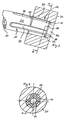
- suction cannula 10 has a tubular or sleeve-shaped base body having a substantially circular cross-section. On the tubular base body, a first end portion is formed as a suction port 12, while a second end portion is realized as a coupling portion 16.
- the suction opening 12 is provided with an integrally formed circumferential bead 14. With its bottom, not shown, the bead 14 forms a contact surface with which the suction cannula 10 can be applied to the oral mucosa, not shown. Adjacent to the suction opening 12, a grip portion 28 is formed with circumferential ribs, which is used for ergonomic favorable and secure holding of the suction cannula 10 by a user.
- the coupling portion 16, together with a komplelentcous coupling socket 20 is a plug connection, via which a connection to a dental suction device, not shown, is made.
- the coupling portion 16 has a cone portion-shaped plug-in portion 18 which is connected to the coupling socket 20 in the FIGS. 2 to 4 is shown in more detail, works together.
- Adjoining the plug-in area 18 in the direction of the free end of the cannula is a substantially cylindrically shaped transition section 22, wherein on an outer surface of the suction cannula 10 between the plug-in area 18 and the Transition portion 22 a circumferential annular shoulder 24 is formed.
- the annular shoulder 24 serves as Einsteckbegrenzung for the suction cannula 10 in the coupling sleeve 20.
- the annular shoulder 24 is arranged between the plug-in portion 18 and the transition portion 22 so that when inserting the suction cannula 10 in the coupling sleeve 20 against a rounded end portion 25 in the coupling socket 20 provided hole 30 runs.
- four groove-shaped axial secondary air channels 26 are formed with a small depth, which are arranged distributed uniformly in the circumferential direction of the suction cannula 10 and extending from the end-side end face 31 of the plug portion 18 beyond the annular shoulder 24 axially toward the suction port 12 ,
- the secondary air channels 26 have a substantially trapezoidal cross-section and are rounded in a semicircular shape in an end region facing away from the plug-in region 18. While acting as sealing surfaces outer surfaces of the plug-in portion 18 abut substantially flat against the tapered bore 30 in the coupling socket 20, the secondary air channels 26 form so with the coupling sleeve 20 flat axial flow channels for ambient air, always from the dental suction device not shown and possibly in addition to Lich to the main air flow flowing through the lumen 34 of the cannula is sucked.
- the secondary air channels 26 are dimensioned such that the sum of all cross sections of the secondary air channels 26 is considerably smaller than the free cross section of the lumen 34 in the suction cannula 10.
- the lumen 34 is configured to have a substantially similar cross-section as a through bore 32 provided in the coupling sleeve 20 to permit at least substantially unthrottled and laminar discharge of the aspirated ambient air toward the dental suction device.
- a plastic material can be used, wherein the production of the suction cannula 10 takes place by injection molding.
- the plastic material is preferably a sterilizable plastic.
- the suction cannula can be provided that a metal alloy is used as a material, wherein a production of the suction cannula can be provided in this case as investment casting, forging or forming part.
Abstract
Description
Die Erfindung betrifft eine Saugkanüle für eine dentale Saugeinrichtung mit einem rohrförmigen Grundkörper, bei dem an voneinander abgewandten Endbereichen eine Saugöffnung und ein zur lösbaren Anbringung an einer Kupplungsbuchse der Saugeinrichtung vorgesehener Kupplungsabschnitt ausgebildet sind.The invention relates to a suction cannula for a dental suction device with a tubular base body, wherein at the end regions remote from each other, a suction opening and a provided for releasable attachment to a coupling socket of the suction device coupling portion are formed.
Eine vom Markt her bekannte Saugkanüle ist als rohrförmiges Kunststoffspritzgußteil hergestellt und ist zu lösbaren Anbringung an einer Saugeinrichtung vorgesehen. Zu diesem Zweck weist die Saugkanüle einen Kupplungsabschnitt auf, der eine dichte Steckverbindung mit einer korrespondierend geformten Kupplungsbuchse der Saugeinrichtung gewährleistet. An einem vom Kupplungsabschnitt abgewandten Endbereich der Saugkanüle ist eine Saugöffnung vorgesehen, die von einem verrundeten, wulstartigen Kragen berandet ist. Der Kragen gewährleistet, dass der zur Anwendung im Mundraum eines Patienten vorgesehene Abschnitt der Saugkanüle frei von scharfen Kanten ist, die eine Verletzung der Mundschleimhaut hervorrufen könnten.A known from the market suction cannula is made as a tubular plastic injection molded part and is provided for releasable attachment to a suction device. For this purpose, the suction cannula on a coupling portion which ensures a tight plug connection with a correspondingly shaped coupling socket of the suction device. At a side remote from the coupling portion end portion of the suction cannula, a suction opening is provided, which is bounded by a rounded, bead-like collar. The collar ensures that the section of the suction cannula intended for use in the oral cavity of a patient is free from sharp edges which could cause an injury to the oral mucosa.
Mit der bekannten Saugkanüle in Verbindung mit der dentalen Saugeinrichtung können während einer Behandlung Flüssigkeiten und/oder Feststoffpartikel aus dem Mundraum des Patienten abgesaugt werden. Um das Absaugen zu ermöglichen, stellt die Saugeinrichtung einen Unterdruck bereit, der ein Einströmen von Umgebungsluft, Flüssigkeiten und Feststoffpartikeln in die Saugkanüle bewirkt.With the known suction cannula in connection with the dental suction device, liquids and / or solid particles can be sucked out of the oral cavity of the patient during a treatment. In order to allow the suction, the suction device provides a negative pressure, which causes an inflow of ambient air, liquids and solid particles into the suction cannula.
Der von der Saugeinrichtung bereitzustellende Unterdruck wird so gewählt, daß sowohl die gewünschte Absaugleistung gewährleistet ist, als auch ein Festsaugen der Saugkanüle an der Mundschleimhaut, wie sie bei flächiger Anlage der Saugöffnung an die Mundschleimhaut auftreten kann, vermieden wird. Eine solches Festsaugen mindert die Saugleistung und erschwert die Handhabung der Saugkanüle.The negative pressure to be provided by the suction device is chosen so that both the desired suction is guaranteed, as well as a firm eye of the suction cannula on the oral mucosa, as it can occur in planar contact of the suction opening to the oral mucosa is avoided. Such a tight eye reduces the suction power and makes handling of the suction cannula more difficult.
Bei bekannten Saugkanülen kann es vorkommen, daß bei Unterbrechung des Luftfstromes in der Kanüle in der letzteren befindliche Flüssigkeit in den Mund des Patienten zurückfließt (Reflux). Dies ist unerwünscht.In known suction cannulas, it may happen that in case of interruption of the Luftfstromes in the cannula liquid located in the latter flows back into the mouth of the patient (reflux). This is undesirable.
Die Aufgabe der Erfindung besteht darin, eine Saugkanüle bereitzustellen, bei der der die Gefahr des Auftretens von Reflux zumindest vermindert, vorzugsweise ausgeräumt ist.The object of the invention is to provide a suction cannula, in which the risk of the occurrence of reflux is at least reduced, preferably eliminated.
Diese Aufgabe wird durch eine Saugkanüle der eingangs genannten Art gelöst, bei der zumindest ein Nebenluftkanal vorgesehen ist, durch den ein Mindestfluidstrom (in der Regel Umgebungsluft) strömen kann.This object is achieved by a suction cannula of the type mentioned, in which at least one secondary air duct is provided, through which a minimum fluid flow (usually ambient air) can flow.
Der an der Saugkanüle vorgesehene Nebenluftkanal gewährleistet neben die Verhinderung oder zumindest Verminderung von Reflux dadurch, dass auch bei einem dichten Anliegen der Saugöffnung an der Mundschleimhaut, welches sonst den Luftstrom durch die Saugkanüle beendet, ein Mindestfluidstrom von der Saugeinrichtung durch die Saugkanüle angesaugt wird.The additional air duct provided on the suction cannula, in addition to preventing or at least reducing reflux, ensures that a minimum flow of fluid from the suction device is sucked in through the suction cannula, even if the suction opening is tight against the oral mucosa, which otherwise stops the air flow through the suction cannula.
Damit wird zugleich eine Begrenzung der von der Saugeinrichtung auf die Mundschleimhaut ausgeübten Saugkraft gewährleistet, so dass die Saugkanüle in einfacher Weise wieder von der Mundschleimhaut oder anderen weichen Gewebeteilen gelöst werden kann.This ensures at the same time limiting the suction force exerted by the suction device on the oral mucous membrane, so that the suction cannula can be easily detached again from the oral mucosa or other soft tissue parts.
Der zumindest eine Nebenluftkanal ist mit seinem Querschnitt erheblich kleiner als ein Querschnitt des rohrförmigen Grundkörpers der Saugkanüle gewählt. Damit wird erreicht, daß bei freier Saugöffnung lediglich ein kleiner Anteil des von der Saugeinrichtung insgesamt angesaugten Fluidstroms durch den Nebenluftkanal angesaugt wird. Bei einem vollständig dichten Anliegen der Saugöffnung an der Mundschleimhaut gewährleistet der durch den Nebenluftkanal strömende Mindestfluidstrom eine Begrenzung des Unterdrucks in der Saugkanüle auf ein vorgebenes Druckniveau, so dass ein leichtes Ablösen erfolgen kann.The at least one secondary air duct is selected with its cross section considerably smaller than a cross section of the tubular base body of the suction cannula. This ensures that, with a free suction opening, only a small portion of the suction of the suction device as a whole sucked fluid flow is sucked through the secondary air duct. In a completely dense concern of the suction opening on the oral mucosa flowing through the secondary air passage minimum fluid flow ensures a limitation of the negative pressure in the suction cannula to a predetermined pressure level, so that a slight detachment can take place.
Vorteilhafte Weiterbildungen der Erfindung sind in Unteransprüchen angegeben.Advantageous developments of the invention are specified in subclaims.
Bei der Gestaltung der Saugkanüle gemäß Anspruch 2 ist vorteilhaft, daß der Nebenluftkanal an einer frei wählbaren Position am Grundkörper angebracht werden kann.In the design of the suction cannula according to claim 2 is advantageous in that the secondary air duct can be attached to a freely selectable position on the base body.
Vorzugsweise sind mehrere Bohrungen am Grundkörper vorgesehen, die beispielsweise in Umfangsrichtung gleichverteilt angeordnet sein können.Preferably, a plurality of holes are provided on the base body, which may be arranged uniformly distributed, for example in the circumferential direction.
Bei einer vorteilhaften Ausführungsform ist zumindest eine Bohrung in einem Bereich der Saugkanüle angeordnet, der von einem Benutzer bei der Verwendung der Saugkanüle mit der Hand ergriffen wird. Dabei kann der Benutzer die Bohrung im Normalfall mit einem oder mehreren Fingern verschlossen halten. Lediglich für den Fall eines Festsaugens gibt der Benutzer die Bohrung durch Abheben des Fingers von der Saugkanüle frei. Damit wird der Nebenluftkanal geöffnet und ein Lösen der Saugkanüle von der Mundschleimhaut wird erleichtert.In an advantageous embodiment, at least one bore is arranged in a region of the suction cannula, which is gripped by a user when using the suction cannula by hand. In this case, the user can keep the hole normally closed with one or more fingers. Only in the case of a fixed suction gives the User free the hole by lifting the finger from the suction cannula. Thus, the secondary air duct is opened and a release of the suction cannula of the oral mucosa is facilitated.
Bei der Gestaltung der Saugkanüle gemäß Anspruch 3 ist vorteilhaft, daß der rohrförmige Grundkörper der Saugkanüle frei von Durchbrechungen ist, die gegebenenfalls ein unerwünschtes Austreten von angesaugter Flüssigkeit, insbesondere an unerwünschten Stellen längs der Saugkanüle, ermöglichen würde. Zudem wird die Stabilität des rohrförmigen Grundkörpers nicht durch Bohrungen oder schlitzförmige Ausnehmungen reduziert, so dass die Saugkanüle mit dünnen Wandstärken verwirklicht werden kann. Darüber hinaus wird vermieden, daß der durch den Nebenluftkanal angesaugte Fluidstrom zu unerwünschten Geräuschen führt, wie dies bei Bohrungen oder Schlitzen im rohrförmigen Grundkörper der Fall sein kann.In the design of the suction cannula according to claim 3 is advantageous in that the tubular body of the suction cannula is free of perforations, which would possibly allow an undesirable leakage of sucked liquid, in particular at undesirable locations along the suction cannula. In addition, the stability of the tubular base body is not reduced by holes or slot-shaped recesses, so that the suction cannula can be realized with thin wall thicknesses. In addition, it is avoided that the sucked through the secondary air duct fluid flow leads to unwanted noise, as may be the case with holes or slots in the tubular body.
Bei der Gestaltung der Saugkanüle gemäß Anspruch 4 ist vorteilhaft, daß der oder die Nebenluftkanäle nicht unmittelbar mit den im Mundraum vorliegenden Flüssigkeiten und/oder Feststoffpartikeln in Kontakt tritt bzw. treten und somit die Gefahr eines Blockierens der Nebenluftkanäle durch diese Flüssigkeiten und/oder Feststoffpartikel reduziert werden kann, wodurch die Funktion der Nebenluftkanäle in Frage gestellt würde. Zudem wird vermieden, dass der Nebenluftkanal oder die Nebenluftkanäle flächig an der Mundschleimhaut anliegen können, so dass dessen bzw. deren Wirkung bei gegebenenfalls zeitgleich verschlossener Saugöffnung aufgehoben wäre.In the design of the suction cannula according to claim 4 is advantageous that the one or more secondary air channels does not directly contact or enter into contact with the liquids and / or solid particles present in the oral cavity and thus reduces the risk of blocking the secondary air channels by these liquids and / or solid particles can be, which would be the function of the secondary air ducts in question. In addition, it is avoided that the secondary air duct or the secondary air ducts can lie flat against the oral mucous membrane, so that its or their effect would be canceled if simultaneously closed suction port.
Bei der Gestaltung der Saugkanüle gemäß Anspruch 5 ist vorteilhaft, daß der oder die Nebenluftkanäle in einfacher Weise im Kunststoffspritzgußverfahren hergestellt werden können. Bei einer Ausrichtung einer Längsachse der nutförmigen Nebenluftkanäle parallel zu einer Trennebene der zur Herstellung verwendeten Kunststoffspritzgussform kann gegebenenfalls auf aufwendige Schieber zur Herstellung der Nebenluftkanäle verzichtet werden.In the design of the suction cannula according to claim 5 is advantageous that the one or more secondary air channels can be prepared in a simple manner by plastic injection molding. In an alignment of a longitudinal axis of the groove-shaped secondary air channels parallel to a parting plane of the plastic injection mold used for the production can be dispensed with expensive slide for the preparation of the secondary air ducts, if necessary.
Bei der Gestaltung der Saugkanäle gemäß Anspruch 6 ist vorteilhaft, daß der oder die Nebenluftkanäle durch ein Zusammenwirken des Kupplungsabschnitts der Saugkanüle und einer korrespondierend geformten Kupplungsbuchse der Saugeinrichtung begrenzt werden. Somit kann auf Hohlräume in der Saugkanüle verzichtet werden, die eine aufwendigere Herstellungstechnik erfordern würden. Damit kann die Saugkanüle einfach und kostengünstig als Massenprodukt hergestellt werden.In the design of the suction channels according to claim 6 is advantageous that the or the secondary air channels are limited by an interaction of the coupling portion of the suction cannula and a correspondingly shaped coupling bushing of the suction device. Thus, it is possible to dispense with cavities in the suction cannula, which would require a more elaborate production technique. Thus, the suction cannula can be easily and inexpensively mass-produced.
Bei der Gestaltung der Saugkanüle gemäß Anspruch 7 ist eine zuverlässige Funktion des oder der Nebenluftkanäle auch bei einem fehlerhaften Einstecken der Saugkanüle in die Kupplungsbuchse der Saugeinrichtung gewährleistet.In the design of the suction cannula according to claim 7, a reliable function of the secondary air channels or even with a faulty insertion of the suction cannula is ensured in the coupling socket of the suction device.
Bei der Gestaltung der Saugkanüle gemäß Anspruch 8 ist vorteilhaft, daß das Risiko für ein fehlerhaftes Einstecken der Saugkanüle in die Kupplungsbuchse der Saugeinrichtung minimiert wird und dass eine übliche Kupplungsbuchse einer Saugeinrichtung ohne jegliche Modifikation eingesetzt werden kann.In the design of the suction cannula according to claim 8 is advantageous that the risk of incorrect insertion of the suction cannula is minimized in the coupling socket of the suction device and that a conventional coupling socket of a suction device can be used without any modification.
Dabei ist vorgesehen, daß bei vollständigem Einstecken der Saugkanüle in die Kupplungsbuchse der Saugeinrichtung bedingt durch die Einsteckbegrenzung ein strömungstechnisch vorteilhafter Ringspalt zwischen der Stirnseite der Saugkanüle und der Kupplungsbuchse gebildet wird Durch den Ringspalt wird ein turbulenzarmes und somit auch geräuscharmes Einströmen des durch den bzw. die Nebenluftkanäle angesaugten Nebenfluidstromes zum Hauptfluid-stroms hin zur Saugeinrichtung erhalten.It is provided that conditionally upon complete insertion of the suction cannula in the coupling socket of the suction device By the insertion limit a fluidically advantageous annular gap between the end face of the suction cannula and the coupling sleeve is formed by the annular gap is a low turbulence and thus low-noise inflow of sucked by the or the secondary air channels auxiliary fluid flow to the main fluid flow towards the suction device.
Bei der Gestaltung der Saugkanüle gemäß Anspruch 9 ist vorteilhaft, daß eine symmetrische Einspeisung des Nebenfluidstromes in den Hauptfluidstroms zur Saugeinrichtung gewährleistet ist.In the design of the suction cannula according to claim 9 is advantageous that a symmetrical feeding of the secondary fluid flow is ensured in the main fluid flow to the suction device.
Nachstehend wird ein Ausführungsbeispiel der Erfindung anhand der Zeichnung näher beschrieben. In dieser zeigen:
- Figur 1
- eine perspektivische Darstellung einer Saugkanüle mit einer Saugöffnung und einem Kupplungsabschnitt, der mit Nebenluftkanälen versehen ist;
- Figur 2
- einer perspektivische Schnittdarstellung des in eine Kupplungsbuchse eingesteckten Kupplungsabschnitts der Saugkanüle gemäß
Figur 1 ; - Figur 3
- einen axialen Schnitt durch die Kupplungsbuchse, wobei zugleich ein eingesteckter Kupplungsabschnitts der Saugkanüle gemäß
Figur 1 gezeigt ist; - Figur 4
- eine transversale Schnittdarstellung des in die Kupplungsbuchse eingesteckten Kupplungsabschnitts der Saugkanüle gemäß der
Figur 1 .
- FIG. 1
- a perspective view of a suction cannula with a suction port and a coupling portion which is provided with secondary air ducts;
- FIG. 2
- a perspective sectional view of the inserted into a coupling socket coupling portion of the suction cannula according to
FIG. 1 ; - FIG. 3
- an axial section through the coupling bush, wherein at the same time an inserted coupling portion of the suction cannula according to
FIG. 1 is shown; - FIG. 4
- a transverse sectional view of the inserted into the coupling socket coupling portion of the suction cannula according to the
FIG. 1 ,
Die in der
Um bei Anwendung der Saugkanüle 10 in der Mundhöhle eines Patienten mechanische Verletzungen zu verhindern, ist die Saugöffnung 12 mit einem angeformten umlaufenden Wulst 14 versehen. Mit seiner nicht näher dargestellten Unterseite bildet der Wulst 14 eine Kontaktfläche, mit der die Saugkanüle 10 an die nicht dargestellte Mundschleimhaut angelegt werden kann. Benachbart zur Saugöffnung 12 ist ein Griffbereich 28 mit umlaufenden Rippen ausgebildet, der zum ergonomischen günstigen und sicheren Halten der Saugkanüle 10 durch einen Benutzer dient.In order to prevent mechanical injuries when using the
Der Kupplungsabschnitt 16 bildet zusammen mit einer komplelentären Kupplungsbuchse 20 eine Steckverbindung , über die eine Verbindung zu einer nicht dargestellten dentalen Saugeinrichtung hergestellt wird.The
Wie in den
An den Steckbereich 18 schließt sich in Richtung auf das freie Kanülenende hin ein im wesentlichen zylindrisch geformter Übergangsabschnitt 22 an, wobei an einer Außenfläche der Saugkanüle 10 zwischen dem Steckbereich 18 und dem Übergangsabschnitt 22 eine umlaufende Ringschulter 24 ausgebildet ist.
Die Ringschulter 24 dient als Einsteckbegrenzung für die Saugkanüle 10 in der Kupplungsbuchse 20. Die Ringschulter 24 ist derart zwischen dem Steckbereich 18 und dem Übergangsabschnitt 22 angeordnet, daß sie beim Einstecken der Saugkanüle 10 in die Kupplungsbuchse 20 gegen einen abgerundeten Endabschnitt 25 einer in der Kupplungsbuchse 20 vorgesehenen Bohrung 30 aufläuft. Damit wird ein zu tiefes Einstecken des Kupplungsabschnitts 16 in die Kupplungsbuchse 20 derart verhindert, dass gewährleistet ist, dass ein Ringkanal 36 zwischen der hinteren Stirnfläche 31 der Saugkanüle 10 und einer Ringschulter 33 der Kupplungsbuchse 20 freibleibt.Adjoining the plug-in
The
An dem Kupplungsabschnitt 16 sind vier nutförmige axiale Nebenluftkanäle 26 mit geringer Tiefe ausgebildet, die in Umfangsrichtung der Saugkanüle 10 gleichverteilt angeordnet sind und die sich ausgehend von der endseitigen Stirnfläche 31 des Steckbereichs 18 über die Ringschulter 24 hinaus axial in Richtung auf die Saugöffnung 12 zu erstrecken.At the
Wie in der
Dabei sind die Nebenluftkanäle 26 derart bemessen, daß die Summe aller Querschnitte der Nebenluftkanäle 26 erheblich kleiner als der freier Querschnitt des Lumens 34 in der Saugkanüle 10 ist. Das Lumen 34 ist seinerseits derart ausgebildet, daß es einen im wesentlichen gleichen Querschnitt wie eine in der Kupplungsbuchse 20 vorgesehene Durchgangsbohrung 32 aufweist, um ein zumindest im wesentlichen ungedrosseltes und laminares Abströmen der angesaugten Umgebungsluft in Richtung der dentalen Saugeinrichtung zu ermöglichen.The
Als Werkstoff für die Saugkanüle 10 kann ein Kunststoffmaterial eingesetzt werden, wobei die Herstellung der Saugkanüle 10 im Spritzgiessverfahren erfolgt. Bei dem Kunststoffmaterial handelt es sich vorzugsweise um einen sterilisierbaren Kunststoff.As a material for the
Bei einer nicht dargestellten Ausführungsform der Saugkanüle kann vorgesehen sein, daß als Werkstoff eine Metalllegierung eingesetzt wird, wobei eine Herstellung der Saugkanüle in diesem Fall als Feinguß-, Schmiede- oder Umformteil vorgesehen sein kann.In one embodiment, not shown, of the suction cannula can be provided that a metal alloy is used as a material, wherein a production of the suction cannula can be provided in this case as investment casting, forging or forming part.
Claims (9)
einem rohrförmigen Grundkörper, bei den an voneinan der abgewandten Endbereichen eine Saugöffnung (12) und ein zur auswechselbaren Anbringung an einer Kupplungsbuchse (20) der Saugeinrichtung vorgesehener Kupplungsabschnitt (16) ausgebildet sind, dadurch gekennzeichnet, daß sie zumindest einen Nebenluftkanal (26) aufweist.Suction cannula (10) for a dental suction with
a tubular base body, in which at voneinan the opposite end portions of a suction opening (12) and a replaceable attachment to a coupling socket (20) of the suction provided coupling portion (16) are formed, characterized in that it comprises at least one secondary air channel (26).
daß mindestens ein Nebenluftkanal eine nicht versehentlich verschließbare Bohrung im Grundkörper ist.Suction cannula according to claim 1, characterized in that
that at least one secondary air duct is a not accidentally closable hole in the body.
daß mindestens ein Nebenluftkanal (26) eine Nut an einer nach außen gewandten Oberfläche des Grundkörpers ist.Suction cannula according to claim 1, characterized in that
in that at least one secondary air channel (26) is a groove on an outwardly facing surface of the base body.
dadurch gekennzeichnet, daß mindestens ein Nebenluftkanal (26) von der Saugöffnung beabstandet ist.Suction cannula according to one of the preceding claims,
characterized in that at least one secondary air channel (26) is spaced from the suction opening.
dadurch gekennzeichnet, daß sich mindestens ein Ne benluftkanal (26) in Richtung einer Mittellängsachse des Grundkörpers erstreckt.Suction cannula according to one of the preceding claims,
characterized in that at least one Ne Benluftkanal (26) extends in the direction of a central longitudinal axis of the base body.
(26) eine Nut in der Außenfläche des Kupplungsabschnitts (16) ist.Suction cannula according to one of claims 3 to 5, characterized in that at least one secondary air channel
(26) a groove in the outer surface of the coupling portion (16) is.
daß sich der Nebenluftkanal (26) über den Kupplungs abschnitt (16) hinauserstreckt.Suction cannula according to claim 6, characterized
that the secondary air channel (26) via the coupling portion (16) hinauserstreckt.
dadurch gekennzeichnet, daß im Bereich des Kupplungsabschnitts (16) mehrere Nebenluftkanäle (26) in Umfangsrichtung gleich verteilt sind.Suction cannula according to one of the preceding claims,
characterized in that in the region of the coupling portion (16) a plurality of secondary air channels (26) are distributed uniformly in the circumferential direction.
Applications Claiming Priority (1)
| Application Number | Priority Date | Filing Date | Title |
|---|---|---|---|
| DE102007006613A DE102007006613A1 (en) | 2007-02-06 | 2007-02-06 | Suction cannula for dental suction device, has auxiliary air duct and base body, on which suction opening and coupling section are formed at end regions that are turned away from each other, where minimum fluid stream flows through air duct |
Publications (2)
| Publication Number | Publication Date |
|---|---|
| EP1955672A1 true EP1955672A1 (en) | 2008-08-13 |
| EP1955672B1 EP1955672B1 (en) | 2018-09-19 |
Family
ID=39345150
Family Applications (1)
| Application Number | Title | Priority Date | Filing Date |
|---|---|---|---|
| EP08001100.0A Active EP1955672B1 (en) | 2007-02-06 | 2008-01-22 | Suction cannula for a dental suction device |
Country Status (2)
| Country | Link |
|---|---|
| EP (1) | EP1955672B1 (en) |
| DE (1) | DE102007006613A1 (en) |
Cited By (2)
| Publication number | Priority date | Publication date | Assignee | Title |
|---|---|---|---|---|
| DE202010009610U1 (en) | 2010-06-28 | 2011-10-14 | DüRR DENTAL AG | Suction cannula for a dental suction device |
| DE202019001370U1 (en) | 2019-03-25 | 2020-06-29 | Coltène/Whaledent GmbH + Co. KG | Two-part suction cannula for dental medical treatments |
Families Citing this family (2)
| Publication number | Priority date | Publication date | Assignee | Title |
|---|---|---|---|---|
| DE102008045877A1 (en) | 2008-09-06 | 2010-03-11 | Bauernschmitt, Robert, Prof. | Medical device for fixing of mitral valve tissue of human patient, has absorption device for absorption of tissue, fixing device for fixing tissue and comprising retainer for surgical wire, and guiding device flexibly retaining anchor wire |
| DE102009013836A1 (en) | 2009-03-21 | 2010-09-23 | DüRR DENTAL AG | suction instrument |
Citations (6)
| Publication number | Priority date | Publication date | Assignee | Title |
|---|---|---|---|---|
| US3881254A (en) | 1974-02-06 | 1975-05-06 | Louis C Epstein | Saliva ejector |
| DE8030146U1 (en) | 1980-11-12 | 1981-03-12 | Hatzfeld, Hermann, 6490 Schlüchtern | DENTAL SUCTION CANNULA |
| EP0152390A2 (en) | 1984-02-13 | 1985-08-21 | Mediplast AB | Suction device |
| EP0457220A1 (en) | 1990-05-14 | 1991-11-21 | Colin Dr. Nates | Suction devices |
| WO1996031170A1 (en) * | 1995-04-07 | 1996-10-10 | White Shield Inc. | Disposable oral suction tip |
| EP1752110A2 (en) | 2005-08-13 | 2007-02-14 | Dürr-Dental GmbH & Co. KG | Adapter for a dental suction device |
-
2007
- 2007-02-06 DE DE102007006613A patent/DE102007006613A1/en not_active Withdrawn
-
2008
- 2008-01-22 EP EP08001100.0A patent/EP1955672B1/en active Active
Patent Citations (6)
| Publication number | Priority date | Publication date | Assignee | Title |
|---|---|---|---|---|
| US3881254A (en) | 1974-02-06 | 1975-05-06 | Louis C Epstein | Saliva ejector |
| DE8030146U1 (en) | 1980-11-12 | 1981-03-12 | Hatzfeld, Hermann, 6490 Schlüchtern | DENTAL SUCTION CANNULA |
| EP0152390A2 (en) | 1984-02-13 | 1985-08-21 | Mediplast AB | Suction device |
| EP0457220A1 (en) | 1990-05-14 | 1991-11-21 | Colin Dr. Nates | Suction devices |
| WO1996031170A1 (en) * | 1995-04-07 | 1996-10-10 | White Shield Inc. | Disposable oral suction tip |
| EP1752110A2 (en) | 2005-08-13 | 2007-02-14 | Dürr-Dental GmbH & Co. KG | Adapter for a dental suction device |
Cited By (3)
| Publication number | Priority date | Publication date | Assignee | Title |
|---|---|---|---|---|
| DE202010009610U1 (en) | 2010-06-28 | 2011-10-14 | DüRR DENTAL AG | Suction cannula for a dental suction device |
| DE202019001370U1 (en) | 2019-03-25 | 2020-06-29 | Coltène/Whaledent GmbH + Co. KG | Two-part suction cannula for dental medical treatments |
| EP3714837A1 (en) | 2019-03-25 | 2020-09-30 | Coltène/Whaledent GmbH + Co. KG | Two-part suction cannula for dental treatment |
Also Published As
| Publication number | Publication date |
|---|---|
| DE102007006613A1 (en) | 2008-08-07 |
| EP1955672B1 (en) | 2018-09-19 |
Similar Documents
| Publication | Publication Date | Title |
|---|---|---|
| EP0631508B1 (en) | Suction catheter | |
| DE60034807T2 (en) | BOLUSSPITZENGESTALTUNG FOR A MULTILING CATHETER | |
| DE60306299T2 (en) | Closed aspiration catheter assembly | |
| DE3900279C2 (en) | Fitting for connection to a tracheal catheter | |
| DE60211172T2 (en) | MALE LUER CONNECTION PART WITH VALVE | |
| DE60119112T2 (en) | MEDICAL VALVE WITH POSITIVE FLOW CHARACTERISTICS | |
| DE3210148C2 (en) | Connector | |
| DE8607358U1 (en) | Tubular, flexible probe for insertion into the trachea and bronchi | |
| EP0625060A1 (en) | Hose coupling, in particular for coupling a flexible catheter to a port of a port-catheter system | |
| WO2017080946A1 (en) | Handheld dental tool | |
| EP1955672B1 (en) | Suction cannula for a dental suction device | |
| DE102006048463A1 (en) | Dental suction device for sucking liquids e.g. saliva, from mouth area, has cap attached with opening in detachable manner over suction opening, where pipe has pipe opening within area of suction opening, and pipe opening is covered by cap | |
| DE60017863T2 (en) | Needle assembly with an elongated blunting device with venting capability | |
| EP3714837B1 (en) | Two-part suction cannula for dental treatment | |
| EP1522272B1 (en) | Two-components suction cannula | |
| DE19907763A1 (en) | Seal for instrument channel in endoscope | |
| EP3568055B1 (en) | Suction mirror having a central wall | |
| DE7822205U1 (en) | MEDICAL SUCTION TUBE | |
| EP3733043B1 (en) | Endoscopic device | |
| DE202010009610U1 (en) | Suction cannula for a dental suction device | |
| DE112022000738T5 (en) | Easily removable medical suction device for a mouth opening | |
| DE202004014828U1 (en) | Endoscopic instrument | |
| EP1234548A2 (en) | Medical or dental treatment instrument with a filter element | |
| DE102020109432A1 (en) | Dental cartridge | |
| EP3719225B1 (en) | Device for dispensing cleaning agent |
Legal Events
| Date | Code | Title | Description |
|---|---|---|---|
| PUAI | Public reference made under article 153(3) epc to a published international application that has entered the european phase |
Free format text: ORIGINAL CODE: 0009012 |
|
| AK | Designated contracting states |
Kind code of ref document: A1 Designated state(s): AT BE BG CH CY CZ DE DK EE ES FI FR GB GR HR HU IE IS IT LI LT LU LV MC MT NL NO PL PT RO SE SI SK TR |
|
| AX | Request for extension of the european patent |
Extension state: AL BA MK RS |
|
| RAP1 | Party data changed (applicant data changed or rights of an application transferred) |
Owner name: DUERR DENTAL AG |
|
| 17P | Request for examination filed |
Effective date: 20090129 |
|
| 17Q | First examination report despatched |
Effective date: 20090317 |
|
| AKX | Designation fees paid |
Designated state(s): AT BE BG CH CY CZ DE DK EE ES FI FR GB GR HR HU IE IS IT LI LT LU LV MC MT NL NO PL PT RO SE SI SK TR |
|
| GRAP | Despatch of communication of intention to grant a patent |
Free format text: ORIGINAL CODE: EPIDOSNIGR1 |
|
| STAA | Information on the status of an ep patent application or granted ep patent |
Free format text: STATUS: GRANT OF PATENT IS INTENDED |
|
| INTG | Intention to grant announced |
Effective date: 20180220 |
|
| RAP1 | Party data changed (applicant data changed or rights of an application transferred) |
Owner name: DUERR DENTAL SE |
|
| GRAS | Grant fee paid |
Free format text: ORIGINAL CODE: EPIDOSNIGR3 |
|
| GRAJ | Information related to disapproval of communication of intention to grant by the applicant or resumption of examination proceedings by the epo deleted |
Free format text: ORIGINAL CODE: EPIDOSDIGR1 |
|
| GRAL | Information related to payment of fee for publishing/printing deleted |
Free format text: ORIGINAL CODE: EPIDOSDIGR3 |
|
| STAA | Information on the status of an ep patent application or granted ep patent |
Free format text: STATUS: EXAMINATION IS IN PROGRESS |
|
| GRAP | Despatch of communication of intention to grant a patent |
Free format text: ORIGINAL CODE: EPIDOSNIGR1 |
|
| STAA | Information on the status of an ep patent application or granted ep patent |
Free format text: STATUS: GRANT OF PATENT IS INTENDED |
|
| INTC | Intention to grant announced (deleted) | ||
| GRAA | (expected) grant |
Free format text: ORIGINAL CODE: 0009210 |
|
| STAA | Information on the status of an ep patent application or granted ep patent |
Free format text: STATUS: THE PATENT HAS BEEN GRANTED |
|
| INTG | Intention to grant announced |
Effective date: 20180731 |
|
| AK | Designated contracting states |
Kind code of ref document: B1 Designated state(s): AT BE BG CH CY CZ DE DK EE ES FI FR GB GR HR HU IE IS IT LI LT LU LV MC MT NL NO PL PT RO SE SI SK TR |
|
| REG | Reference to a national code |
Ref country code: GB Ref legal event code: FG4D Free format text: NOT ENGLISH |
|
| REG | Reference to a national code |
Ref country code: CH Ref legal event code: EP |
|
| REG | Reference to a national code |
Ref country code: AT Ref legal event code: REF Ref document number: 1042362 Country of ref document: AT Kind code of ref document: T Effective date: 20181015 |
|
| REG | Reference to a national code |
Ref country code: IE Ref legal event code: FG4D Free format text: LANGUAGE OF EP DOCUMENT: GERMAN |
|
| REG | Reference to a national code |
Ref country code: DE Ref legal event code: R096 Ref document number: 502008016347 Country of ref document: DE |
|
| REG | Reference to a national code |
Ref country code: NL Ref legal event code: MP Effective date: 20180919 |
|
| PG25 | Lapsed in a contracting state [announced via postgrant information from national office to epo] |
Ref country code: LT Free format text: LAPSE BECAUSE OF FAILURE TO SUBMIT A TRANSLATION OF THE DESCRIPTION OR TO PAY THE FEE WITHIN THE PRESCRIBED TIME-LIMIT Effective date: 20180919 Ref country code: NO Free format text: LAPSE BECAUSE OF FAILURE TO SUBMIT A TRANSLATION OF THE DESCRIPTION OR TO PAY THE FEE WITHIN THE PRESCRIBED TIME-LIMIT Effective date: 20181219 Ref country code: FI Free format text: LAPSE BECAUSE OF FAILURE TO SUBMIT A TRANSLATION OF THE DESCRIPTION OR TO PAY THE FEE WITHIN THE PRESCRIBED TIME-LIMIT Effective date: 20180919 Ref country code: SE Free format text: LAPSE BECAUSE OF FAILURE TO SUBMIT A TRANSLATION OF THE DESCRIPTION OR TO PAY THE FEE WITHIN THE PRESCRIBED TIME-LIMIT Effective date: 20180919 Ref country code: GR Free format text: LAPSE BECAUSE OF FAILURE TO SUBMIT A TRANSLATION OF THE DESCRIPTION OR TO PAY THE FEE WITHIN THE PRESCRIBED TIME-LIMIT Effective date: 20181220 Ref country code: BG Free format text: LAPSE BECAUSE OF FAILURE TO SUBMIT A TRANSLATION OF THE DESCRIPTION OR TO PAY THE FEE WITHIN THE PRESCRIBED TIME-LIMIT Effective date: 20181219 |
|
| REG | Reference to a national code |
Ref country code: LT Ref legal event code: MG4D |
|
| PG25 | Lapsed in a contracting state [announced via postgrant information from national office to epo] |
Ref country code: LV Free format text: LAPSE BECAUSE OF FAILURE TO SUBMIT A TRANSLATION OF THE DESCRIPTION OR TO PAY THE FEE WITHIN THE PRESCRIBED TIME-LIMIT Effective date: 20180919 Ref country code: HR Free format text: LAPSE BECAUSE OF FAILURE TO SUBMIT A TRANSLATION OF THE DESCRIPTION OR TO PAY THE FEE WITHIN THE PRESCRIBED TIME-LIMIT Effective date: 20180919 |
|
| PG25 | Lapsed in a contracting state [announced via postgrant information from national office to epo] |
Ref country code: RO Free format text: LAPSE BECAUSE OF FAILURE TO SUBMIT A TRANSLATION OF THE DESCRIPTION OR TO PAY THE FEE WITHIN THE PRESCRIBED TIME-LIMIT Effective date: 20180919 Ref country code: ES Free format text: LAPSE BECAUSE OF FAILURE TO SUBMIT A TRANSLATION OF THE DESCRIPTION OR TO PAY THE FEE WITHIN THE PRESCRIBED TIME-LIMIT Effective date: 20180919 Ref country code: NL Free format text: LAPSE BECAUSE OF FAILURE TO SUBMIT A TRANSLATION OF THE DESCRIPTION OR TO PAY THE FEE WITHIN THE PRESCRIBED TIME-LIMIT Effective date: 20180919 Ref country code: CZ Free format text: LAPSE BECAUSE OF FAILURE TO SUBMIT A TRANSLATION OF THE DESCRIPTION OR TO PAY THE FEE WITHIN THE PRESCRIBED TIME-LIMIT Effective date: 20180919 Ref country code: IS Free format text: LAPSE BECAUSE OF FAILURE TO SUBMIT A TRANSLATION OF THE DESCRIPTION OR TO PAY THE FEE WITHIN THE PRESCRIBED TIME-LIMIT Effective date: 20190119 Ref country code: PL Free format text: LAPSE BECAUSE OF FAILURE TO SUBMIT A TRANSLATION OF THE DESCRIPTION OR TO PAY THE FEE WITHIN THE PRESCRIBED TIME-LIMIT Effective date: 20180919 Ref country code: EE Free format text: LAPSE BECAUSE OF FAILURE TO SUBMIT A TRANSLATION OF THE DESCRIPTION OR TO PAY THE FEE WITHIN THE PRESCRIBED TIME-LIMIT Effective date: 20180919 |
|
| PGFP | Annual fee paid to national office [announced via postgrant information from national office to epo] |
Ref country code: MC Payment date: 20190329 Year of fee payment: 12 |
|
| PG25 | Lapsed in a contracting state [announced via postgrant information from national office to epo] |
Ref country code: SK Free format text: LAPSE BECAUSE OF FAILURE TO SUBMIT A TRANSLATION OF THE DESCRIPTION OR TO PAY THE FEE WITHIN THE PRESCRIBED TIME-LIMIT Effective date: 20180919 Ref country code: PT Free format text: LAPSE BECAUSE OF FAILURE TO SUBMIT A TRANSLATION OF THE DESCRIPTION OR TO PAY THE FEE WITHIN THE PRESCRIBED TIME-LIMIT Effective date: 20190119 |
|
| REG | Reference to a national code |
Ref country code: DE Ref legal event code: R097 Ref document number: 502008016347 Country of ref document: DE |
|
| PLBE | No opposition filed within time limit |
Free format text: ORIGINAL CODE: 0009261 |
|
| STAA | Information on the status of an ep patent application or granted ep patent |
Free format text: STATUS: NO OPPOSITION FILED WITHIN TIME LIMIT |
|
| PG25 | Lapsed in a contracting state [announced via postgrant information from national office to epo] |
Ref country code: DK Free format text: LAPSE BECAUSE OF FAILURE TO SUBMIT A TRANSLATION OF THE DESCRIPTION OR TO PAY THE FEE WITHIN THE PRESCRIBED TIME-LIMIT Effective date: 20180919 |
|
| 26N | No opposition filed |
Effective date: 20190620 |
|
| PG25 | Lapsed in a contracting state [announced via postgrant information from national office to epo] |
Ref country code: MC Free format text: LAPSE BECAUSE OF FAILURE TO SUBMIT A TRANSLATION OF THE DESCRIPTION OR TO PAY THE FEE WITHIN THE PRESCRIBED TIME-LIMIT Effective date: 20180919 |
|
| REG | Reference to a national code |
Ref country code: CH Ref legal event code: PL |
|
| GBPC | Gb: european patent ceased through non-payment of renewal fee |
Effective date: 20190122 |
|
| PG25 | Lapsed in a contracting state [announced via postgrant information from national office to epo] |
Ref country code: LU Free format text: LAPSE BECAUSE OF NON-PAYMENT OF DUE FEES Effective date: 20190122 |
|
| REG | Reference to a national code |
Ref country code: BE Ref legal event code: MM Effective date: 20190131 |
|
| REG | Reference to a national code |
Ref country code: IE Ref legal event code: MM4A |
|
| PG25 | Lapsed in a contracting state [announced via postgrant information from national office to epo] |
Ref country code: SI Free format text: LAPSE BECAUSE OF FAILURE TO SUBMIT A TRANSLATION OF THE DESCRIPTION OR TO PAY THE FEE WITHIN THE PRESCRIBED TIME-LIMIT Effective date: 20180919 |
|
| PG25 | Lapsed in a contracting state [announced via postgrant information from national office to epo] |
Ref country code: BE Free format text: LAPSE BECAUSE OF NON-PAYMENT OF DUE FEES Effective date: 20190131 |
|
| PG25 | Lapsed in a contracting state [announced via postgrant information from national office to epo] |
Ref country code: CH Free format text: LAPSE BECAUSE OF NON-PAYMENT OF DUE FEES Effective date: 20190131 Ref country code: LI Free format text: LAPSE BECAUSE OF NON-PAYMENT OF DUE FEES Effective date: 20190131 Ref country code: GB Free format text: LAPSE BECAUSE OF NON-PAYMENT OF DUE FEES Effective date: 20190122 |
|
| PG25 | Lapsed in a contracting state [announced via postgrant information from national office to epo] |
Ref country code: IE Free format text: LAPSE BECAUSE OF NON-PAYMENT OF DUE FEES Effective date: 20190122 |
|
| REG | Reference to a national code |
Ref country code: AT Ref legal event code: MM01 Ref document number: 1042362 Country of ref document: AT Kind code of ref document: T Effective date: 20190122 |
|
| PG25 | Lapsed in a contracting state [announced via postgrant information from national office to epo] |
Ref country code: TR Free format text: LAPSE BECAUSE OF FAILURE TO SUBMIT A TRANSLATION OF THE DESCRIPTION OR TO PAY THE FEE WITHIN THE PRESCRIBED TIME-LIMIT Effective date: 20180919 |
|
| PG25 | Lapsed in a contracting state [announced via postgrant information from national office to epo] |
Ref country code: AT Free format text: LAPSE BECAUSE OF NON-PAYMENT OF DUE FEES Effective date: 20190122 |
|
| PG25 | Lapsed in a contracting state [announced via postgrant information from national office to epo] |
Ref country code: MT Free format text: LAPSE BECAUSE OF FAILURE TO SUBMIT A TRANSLATION OF THE DESCRIPTION OR TO PAY THE FEE WITHIN THE PRESCRIBED TIME-LIMIT Effective date: 20180919 |
|
| PG25 | Lapsed in a contracting state [announced via postgrant information from national office to epo] |
Ref country code: FR Free format text: LAPSE BECAUSE OF NON-PAYMENT OF DUE FEES Effective date: 20200131 |
|
| PG25 | Lapsed in a contracting state [announced via postgrant information from national office to epo] |
Ref country code: CY Free format text: LAPSE BECAUSE OF FAILURE TO SUBMIT A TRANSLATION OF THE DESCRIPTION OR TO PAY THE FEE WITHIN THE PRESCRIBED TIME-LIMIT Effective date: 20180919 |
|
| PG25 | Lapsed in a contracting state [announced via postgrant information from national office to epo] |
Ref country code: HU Free format text: LAPSE BECAUSE OF FAILURE TO SUBMIT A TRANSLATION OF THE DESCRIPTION OR TO PAY THE FEE WITHIN THE PRESCRIBED TIME-LIMIT; INVALID AB INITIO Effective date: 20080122 |
|
| PGFP | Annual fee paid to national office [announced via postgrant information from national office to epo] |
Ref country code: IT Payment date: 20230126 Year of fee payment: 16 Ref country code: DE Payment date: 20230130 Year of fee payment: 16 |
|
| P01 | Opt-out of the competence of the unified patent court (upc) registered |
Effective date: 20230521 |