EP0631508B1 - Suction catheter - Google Patents
Suction catheter Download PDFInfo
- Publication number
- EP0631508B1 EP0631508B1 EP93906567A EP93906567A EP0631508B1 EP 0631508 B1 EP0631508 B1 EP 0631508B1 EP 93906567 A EP93906567 A EP 93906567A EP 93906567 A EP93906567 A EP 93906567A EP 0631508 B1 EP0631508 B1 EP 0631508B1
- Authority
- EP
- European Patent Office
- Prior art keywords
- distal end
- suction catheter
- lumen
- catheter
- suction
- Prior art date
- Legal status (The legal status is an assumption and is not a legal conclusion. Google has not performed a legal analysis and makes no representation as to the accuracy of the status listed.)
- Expired - Lifetime
Links
Images
Classifications
-
- A—HUMAN NECESSITIES
- A61—MEDICAL OR VETERINARY SCIENCE; HYGIENE
- A61M—DEVICES FOR INTRODUCING MEDIA INTO, OR ONTO, THE BODY; DEVICES FOR TRANSDUCING BODY MEDIA OR FOR TAKING MEDIA FROM THE BODY; DEVICES FOR PRODUCING OR ENDING SLEEP OR STUPOR
- A61M25/00—Catheters; Hollow probes
- A61M25/0067—Catheters; Hollow probes characterised by the distal end, e.g. tips
- A61M25/0068—Static characteristics of the catheter tip, e.g. shape, atraumatic tip, curved tip or tip structure
- A61M25/007—Side holes, e.g. their profiles or arrangements; Provisions to keep side holes unblocked
-
- Y—GENERAL TAGGING OF NEW TECHNOLOGICAL DEVELOPMENTS; GENERAL TAGGING OF CROSS-SECTIONAL TECHNOLOGIES SPANNING OVER SEVERAL SECTIONS OF THE IPC; TECHNICAL SUBJECTS COVERED BY FORMER USPC CROSS-REFERENCE ART COLLECTIONS [XRACs] AND DIGESTS
- Y10—TECHNICAL SUBJECTS COVERED BY FORMER USPC
- Y10S—TECHNICAL SUBJECTS COVERED BY FORMER USPC CROSS-REFERENCE ART COLLECTIONS [XRACs] AND DIGESTS
- Y10S604/00—Surgery
- Y10S604/902—Suction wands
Definitions
- the invention relates to a suction catheter according to the preamble of claim 1.
- the invention further relates to a further development of the suction catheter, which can be connected at the proximal end to a connector or the like, and the lumen at the distal end of the catheter tube has a distal outlet opening of the lumen that is enlarged compared to the cross section of the lumen.
- Suction catheters of the generic type are known for example from DE-AS 2364119 or US-PS 3848 604.
- a suction snorkel for sucking saliva from the oral cavity for dental purposes is known, which is thickened on the outside at its distal end, the thickening being interrupted on the outside by radially extending notches.
- a similarly designed suction snorkel for dental purposes is shown in US Pat. No. 2,574,135.
- the snorkel end is thickened in the form of a cylindrical piston and has notches on the outside that extend to the distal outlet opening.
- Suction catheters are usually in addition to the distal one Exit opening at the end equipped with at least one side hole. If the suction catheter comes into close contact with the mucous membrane, it lifts the mucous membrane due to the negative pressure and invaginates it in these side holes or in the outlet opening. The resulting injuries serve as breeding grounds for bacteria and lead to edema, etc.
- a rounded annular bead is formed at the distal end of the suction catheter to avoid injuries to the mucous membrane and extends radially at the end of the catheter over the circumference protrudes from the catheter.
- the catheter is centered within the trachea and is also intended to create a laminar air cushion so that it does not come into contact with the wall of the trachea and no mucous membrane is to be drawn into the catheter.
- the retraction of mucous membrane into the radial lateral openings of the catheter cannot be avoided in all cases.
- the exit opening of this catheter can be made slightly larger than the cross-section of the lumen by rounding.
- the invention has for its object to constructively improve the known suction catheter so that clogging of the distal end by mucus during suction is avoided and also the sticking or sucking in of mucous membrane into the distal outlet opening or the lateral openings in the region of the distal end of the catheter Security can be avoided.
- the distal end region of the suction catheter as a cylindrical piston, a flat guidance of the suction catheter in the airways, such as the trachea, is created, which also prevents the mucous membranes from being sucked into the ventilation openings of the catheter following the proximal end of the suction catheter. Clogging of the ventilation openings by mucus is also avoided.
- the present invention remedies this, since it prevents a clogging of the same with viscous secretion in the area of the outlet opening, ie it enables rapid suction and thus prevents the suction catheter from being sucked onto the mucous membranes via the ventilation openings. It has been found that air is drawn in via the radial ventilation openings, so that the lung segments do not collapse when suctioning secretions from the bronchial space. To enable this ventilation, it is necessary to keep certain distances between the Ventilation openings and the thickened regions formed in the distal end region of the suction catheter in the form of a cylindrical piston part are of importance in order to maintain this ventilation. This distance between the ventilation openings of the suction catheter and the proximal beginning of the cylindrical outer wall of the piston should be less than 6 mm. This distance must be maintained regardless of the size of the suction catheter.
- suction catheters of the generic type can be found in the characterizing features of the subclaims.
- the funnel-shaped widening of the outlet of the lumen at the distal end of the suction catheter it is also possible to widen the funnel and / or the lumen walls by means of notches running into the walls and running in the axial direction.
- the notches can extend into the lumen equally far, less far or further than the funnel-shaped widening in the axial direction.
- the advantageous widening of the distal outlet opening in connection with the thickened area serving as a sealing and guide piston near the distal end of the suction catheter reliably avoids clogging of the distal end of the suction catheter.
- the inventive design of the catheter tube at the distal end also contributes to this, which, viewed in axial cross section, ends tapered by means of the transition zone.
- the additional notches in partial areas of the distal exit opening, which are pressed into the walls of the funnel-shaped enlargement are made relatively small, but are formed over the enlarged exit area into the normal lumen area.
- the notches extend equally far, viewed from the distal end of the catheter tube, like an equally shaped funnel into the lumen in the axial direction.
- An essential embodiment of the suction catheter according to the invention can also be seen in the fact that the thickened area formed in the distal end region of the suction catheter in the shape of the cylindrical piston with its outer diameter determines the size in CH (Charr) according to the ISO standard of the suction catheter and this up to the proximal end of the suction catheter connecting the catheter tube with the opposite, ie compared to the cylindrical piston and the distal end region, reduced outer diameter is formed.
- CH Charger
- the size of the suction catheter in career has been determined according to the outer diameter of the long catheter tube, for example also in the case of suction catheters according to DE-AS 2364119.
- the outer diameter of the cylindrical piston of the thickened area within the distal end area in connection with the diameter of the continuous lumen used for suctioning is used to determine the sizes of the suction catheter, measured in CH according to ISO standard.
- the inventive design of the distal end region with a cylindrical piston, which projects with its outer diameter beyond the other catheter tube, can also be used for suction catheters with two lumens, as shown, for example, in FIG DE-PS 3608943 are used.
- a suction catheter with a suction catheter formed by a thickened area in the form of a cylindrical piston within the distal end region of the catheter tube and which takes over the guiding of the suction catheter when it is introduced into the tracheal bronchial system of a patient can be found in the subclaims.
- the size of the plunger and advantageously the size of the funnel of the funnel-like widening of the distal outlet opening are decisive for the proper functioning of the suction catheter according to the invention as an atraumatic catheter.
- the advantageous expansion of the lumen at the outlet end of the catheter tube can be designed as a funnel, conical or trumpet-shaped, expanded or by means of notches that extend into the lumen walls and extend to the distal end of the catheter tube, or a combination of funnel-like extensions and notches be.
- the preferred dimensions for the design of the suction catheter according to the invention according to the features of claims 6 to 10 are aligned with the standardized suction catheter sizes from 8 CH to 18 CH, whereby usual manufacturing tolerances have to be taken into account.
- the catheter tube for the suction catheter is made of suitable sterilizable thermoplastic materials, which are extrudable, by extrusion with subsequent deformation.
- the suction catheter or the catheter tube are made of a non-toxic, flexible, flexible material, such as, for example natural or synthetic rubber, polypropylene, polyethylene, polyvinyl chloride or polyamides.
- the rigidity of the material can be selected so that even with long suction catheters, which generally have a length of between 50 and 65 cm for the specified sizes from 8 CH to 18 CH, sufficient rigidity and kink resistance is achieved, even with very thin walls of the catheter tube.
- the length a of the cylindrical piston should be sufficient, depending on the size of the catheter, to allow adequate flat contact and guidance of the catheter or catheter end in the airways.
- the transition zones adjoining on both sides form conical or approximately conical or rounded transitions from the cylindrical piston on one side directly into an axial end bead of the catheter tube at the distal outlet opening and on the other side to the catheter tube extending towards the proximal end. These transitions are inclined gently and preferably on both sides at the same angles and approximately the same length.
- distal end of the catheter tube tapers into a rounded end that has a smaller outer diameter than the piston of the thickened area of the catheter tube. This end allows the suction catheter to be gently inserted gently into a patient's trachea.
- the proximal end of the suction catheter can, however, be provided with a connection piece, for example a funnel can also be equipped with other parts or connected to devices.
- the proximal end of the suction catheter itself can also be designed to be flared.
- the distal end region of the suction catheter is usually provided in a straight longitudinal extension of the catheter tube, but it can also be bent one or more times with respect to the longitudinal axis of the suction catheter.
- the thickened area for guiding the suction catheter within the distal end area is in front of the bent end part, i.e. in the straight part of the catheter tube.
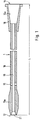
- FIG. 1 schematically shows a suction catheter 1 for suctioning secretions and other fluids from a patient's tracheobronchial space, which can be inserted through the patient's trachea into the bronchial space.
- the suction catheter is firmly connected at its proximal end 11 in the example shown to a connecting piece 16, for example a funnel with an inner funnel 16a.
- the suction catheter can also be connected to other connectors.
- the suction catheter 1 contains the catheter tube 10, which is formed within the distal end region with a thickening in the form of a cylindrical piston 10a.
- the only continuous lumen 13 of the suction catheter 1 formed in the catheter tube opens at the distal end 12 in the distal outlet opening 21.
- Suction catheters of the type shown usually have a length L of between approximately 50 to 65 cm.
- the inner diameter of the continuous lumen 13 is, for example, 1.54 mm for a CH 10 catheter size and 3.0 mm for a CH 16 catheter size.
- the suction catheter 1 according to FIG. 1 has a piston-shaped thickening in the distal end region compared to the rest of the catheter tube 10, specifically in the form of the cylindrical piston 10a.
- the outer diameter to be used for determining the standard size of the suction catheter 1 is that of the piston 10a as the thickest part of the area of the catheter tube to be inserted into the tracheal bronchial space.
- the outside diameter of the catheter tube 10 adjoining the thickened region 10a, 17, 18, which extends to the proximal end 11 of the suction catheter, is smaller than the outside diameter 10a of the piston, i.e. the catheter tube 10 is smaller than the piston 10a.
- the pistons 10a of the suction catheter are adjoined in the direction of the proximal end 11 of the suction catheter by relatively close ventilation openings 15 which extend radially through the wall of the catheter tube 10 and which connect the lumen 13 to the environment.
- the ventilation openings 15 as bores are uniform over the The circumference of the catheter tube 10 is distributed, for example two or four ventilation openings 15.
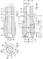
- FIGS. 2 to 3a The distal end region of the suction catheter 1 according to FIG. 1 is shown enlarged in FIGS. 2 to 3a, and the embodiments according to the invention are explained in more detail here.
- the longitudinal section through the distal end region of the suction catheter 1 according to FIG. 3 shows the club-shaped configuration of the distal end region with the cylindrical piston 10a.
- the cylindrical piston 10a falls on both sides, i.e. both towards the distal end 12 and towards the proximal end via a conical transition zone 18 or 17.
- the transition zone 18 merges directly into the rounded end 20, which delimits the distal outlet opening 21.
- the transition zone 17 goes into the catheter tube 10, i.e. its outer wall, over. All transitions are smooth and rounded.
- This funnel-shaped extension 21a opens into the outlet opening 21.
- the outlet opening 21 of the continuous lumen 13 at the distal end 12 of the suction catheter 1 is thus larger in cross section than the cross section of the lumen 13.
- the funnel-shaped extension of the lumen of the catheter tube is of straight or slightly rounded walls limited.
- the outlet opening 21 is delimited by the rounded end 20 of the catheter tube, which forms the rounded axial end of the catheter tube.
- This annular axial bead 20 merges directly into the cylindrical piston 10a on the outside via a conical transition zone 18. Viewed in cross section, the bead is tapered on both sides.
- the suction catheter 1 In the proximal direction follows the cylindrical one Piston 10a of the distal end region after the conical transition zone 17 tapering the catheter tube 10, and immediately thereafter the ventilation openings 15, which connect the lumen 13 to the environment, are formed in the walls of the catheter tube. If the suction catheter 1 is now inserted into a bronchial system for suction and a vacuum is applied, secretion is sucked out of the bronchial space in the direction of the distal outlet opening 21.
- the funnel adjoining the outlet opening 21 advantageously prevents the outlet opening 21 and the lumen 13 from becoming clogged with viscous secretion, since, as a result of the funnel-shaped expansion, an air stream is also sucked in in addition to the secretion, so that the viscous secretion is sucked into the lumen 13 and thus can be dissipated.
- ventilation is additionally made possible, so that here also in the side area, in particular also due to the space between the piston 10a and the catheter tube 10, suction of mucous membranes, ie sticking to the same and thus damage to the same, is prevented.
- the formation of the tapered end 20 of the catheter tube at the outlet opening 21 also prevents seizure.
- the dimensions of the plunger and, in addition, the funnel-shaped widening are important for the proper functioning of the suction catheter designed according to the invention with a distal end region thickened in the form of a plunger.
- the preferred dimensions are given according to FIG. 3a.
- the angles ⁇ and ⁇ for the approximately conical transitions of the cylindrical piston 10a in the direction of the distal end 12 and in the direction of the proximal end, ie to the catheter tube 10, are between 10 ° to 20 ° and should have rounded transitions.
- the inner diameter DI for catheter sizes 8 to 18 CH is between 1.0 and 4.0 mm with an outer diameter DK measured in the area of the cylindrical piston at the distal end area of the suction catheter between 2.7 and 6.1 mm plus manufacturing tolerances.
- wall thicknesses SK in the area of the cylindrical piston of approximately 0.7 to 1.5 mm.
- the tapered outer diameter of the catheter tube 10 DR in relation to the piston 10a is approximately between 1.7 and 5.1 mm, so that this results in wall thicknesses SR of approximately 0.3 to 0.9 mm for the catheter tube.
- the diameter c of the ventilation openings is between 0.25 and 0.8 mm.
- the depth t of the funnel-shaped enlargement should be between 2 and 4 mm
- the diameter DA of the outlet opening at the outlet, ie in the region of the end bead 20 should be approximately 1.25 to 4.3 mm, ie approximately 0.2 to 0.7 mm larger than the associated inner diameter of the lumen 13.
- the outer diameter DW of the end bead 20 should be between 0.4 and 0.8 mm larger than the diameter DA of the outlet opening.
- the smaller values must always be assigned to the smaller CH sizes of the suction catheter.
- the length b1, b2 of the transition zones 17, 18 of the distal end region i.e.
- the length of the piston 10a should preferably be of the same length, these lengths being between approximately 1.5 mm to 3.0 mm.
- the length a of the cylindrical piston 10a should be at least 2 mm to a maximum of 8 mm and preferably in the range of approximately 3.0 to 5 mm.
- Essential for sufficient ventilation through the ventilation openings 15 when the suction catheter is inserted into the bronchial system is the free space between the piston 10a and the ventilation openings 15, ie the distance f or f1.
- the distance f1 is preferably chosen with a constant size for all catheters, preferably about 2.0 to 3.0 mm.
- the total length Lf of the distal end region designed according to the invention from the distal end to the bore axis of the ventilation openings 15 should be 6 to 16 mm and, according to the catheter sizes from CH 8 to CH 18, should also preferably be constant and in each case between 8 to 12 mm, preferably be 10 mm.
- the length lk of the region 17, 10a, 18 of the catheter tube that is thickened relative to the catheter tube 10 is preferably approximately 7 to 9 mm.
- a CH 12 suction catheter has, for example, the following dimensions (manufacturing tolerances can be added): DI 2.0 mm, DR 3.0 mm, DK 4.0 mm, DA 2.31 mm, DW 3.0 mm, t 3 , 25 mm to 4.0 mm, b1, b2 1.65 mm, lk 7.5 mm; f1 2.5 mm; lf 10 mm, ⁇ / ⁇ 17 °; c 0.8 mm.
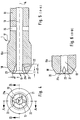
- FIGS. 4 to 6 show a suction catheter 1 according to the invention, the distal end region of which has a small funnel-shaped enlargement 21a and additional axially extending notches 21, 22 which are pressed into the wall delimiting the funnel 21a and the lumen 13.
- the distal outlet opening 21 forms a circular area, the cross section of which is larger than the cross section of the lumen 13.
- This distal outlet opening 21 is radially expanded in some areas by additional notches 22, 23.
- These notches 22, 23, which are evenly distributed over the circumference, for example two notches lying opposite one another, as shown, or two additional notches offset from one another by 90 °, deepen the funnel of the outlet opening at two points in the radial direction.
- these notches 22, 23 not only run in the region of the funnel of the outlet opening 21, but also extend further over the catheter in the axial direction into the lumen 13. This can also be seen from the view according to FIG. 4.
- Notches formed should have a depth d1, measured from the lumen wall in the radial direction of d1, of approximately 0.1 to 0.3 mm and a length d2, measured from the distal end in the axial direction, of approximately 2 to 4 mm.
- the width d3 of the notches, see FIG. 2 should in any case be smaller than the diameter of the lumen 13, in particular approximately 1/7 to 1/4 of the diameter DI of the lumen 13.
- the formation of the distal end region prevents any injuries when suctioning off the mucous membranes and also prevents the suction catheter from becoming blocked with secretions.
Abstract
Description
Die Erfindung betrifft einen Absaugkatheter gemäß dem Oberbegriff des Anspruches 1.The invention relates to a suction catheter according to the preamble of claim 1.
Die Erfindung betrifft des weiteren eine Weiterbildung des Absaugkatheters, der am proximalen Ende mit einem Anschlußstück oder dergleichen verbindbar ist und wobei das Lumen am distalen Ende des Katheterrohres eine gegenüber dem Querschnitt des Lumens vergrößerte distale Austrittsöffnung des Lumens aufweist.The invention further relates to a further development of the suction catheter, which can be connected at the proximal end to a connector or the like, and the lumen at the distal end of the catheter tube has a distal outlet opening of the lumen that is enlarged compared to the cross section of the lumen.
Absaugkatheter der gattungsgemäßen Art sind beispielswiese aus der DE-AS 2364119 bzw. US-PS 3848 604 bekannt.Suction catheters of the generic type are known for example from DE-AS 2364119 or US-PS 3848 604.
Aus der US-PS 2130 406 ist ein Saugschnorchel zum Absaugen von Speichel aus dem Mundraum für zahnärztliche Zwecke bekannt, der an seinem distalen Ende außenseitig verdickt ist, wobei die Verdickung durch radial verlaufende Kerben außenseitig unterbrochen ist.From US-PS 2130 406 a suction snorkel for sucking saliva from the oral cavity for dental purposes is known, which is thickened on the outside at its distal end, the thickening being interrupted on the outside by radially extending notches.
Einen ähnlich gestalteten Saugschnorchel für zahnärztliche Zwecke zeigt die US-PS 2574 135. Hierbei ist das Schnorchelende in Gestalt eines zylindrischen Kolbens verdickt und weist außenseitige, bis an die distale Austrittsöffnung reichende Kerben auf.A similarly designed suction snorkel for dental purposes is shown in US Pat. No. 2,574,135. Here, the snorkel end is thickened in the form of a cylindrical piston and has notches on the outside that extend to the distal outlet opening.
Beim Absaugen von Schleim aus dem Tracheobronchialraum mittels Absaugkathetern kann ein andauerndes Vakuum während des Absaugens zu ernsten Verletzungen der Schleimhaut führen. Zum einen besteht die Gefahr, daß der Absaugkatheter an der Schleimheit klebt und direkt von ihr fortgezogen wird. Absaugkatheter sind üblicherweise zusätzlich zu der distalen Austrittsöffnung am Ende mit mindestens einem Seitenloch ausgestattet. Wenn der Absaugkatheter in enge Berührung mit der Schleimhaut kommt, hebt er durch den Unterdruck die Schleimhaut an und invaginiert sie in diese Seitenlöcher oder auch in die Austrittsöffnung. Die dadurch entstehenden Verletzungen dienen als Brutstätte für Bakterien und führen zu Ödemen usw.When suctioning mucus from the tracheobronchial space using suction catheters, a continuous vacuum during suction can lead to serious injuries to the mucous membrane. On the one hand, there is a risk that the suction catheter sticks to the mucus and is pulled away from it directly. Suction catheters are usually in addition to the distal one Exit opening at the end equipped with at least one side hole. If the suction catheter comes into close contact with the mucous membrane, it lifts the mucous membrane due to the negative pressure and invaginates it in these side holes or in the outlet opening. The resulting injuries serve as breeding grounds for bacteria and lead to edema, etc.
Bei dem aus der DE-A-2364119, die zur Bildung des Oberbegriffs des Anspruchs 1 herangezogen worden ist, bekannten Katheter ist zur Vermeidung von Verletzungen der Schleimhaut am distalen Ende des Absaugkatheters ein abgerundeter Ringwulst ausgebildet, der radial am Ende des Katheters über den Umfang des Katheters vorsteht. Mit Hilfe dieses Ringwulstes wird der Katheter innerhalb der Luftröhre zentriert und soll des weiteren ein laminares Luftpolster schaffen, damit er nicht mit der Wand der Luftröhre in Berührung kommt und auch keine Schleimhaut in den Katheter eingesogen werden soll. Es hat sich jedoch herausgestellt, daß nicht in allen Fällen das Einziehen von Schleimhaut in die radialen seitlichen Öffnungen des Katheters vermieden werden kann. Darüber hinaus stellt sich in manchen Fällen das Problem, daß die distale Austrittsöffnung durch Schleim verstopft wird. Die Austrittsöffnung dieses Katheters kann durch Abrundung leicht gegenüber dem Querschnitt des Lumens vergrößert ausgebildet sein.In the catheter known from DE-A-2364119, which has been used to form the preamble of claim 1, a rounded annular bead is formed at the distal end of the suction catheter to avoid injuries to the mucous membrane and extends radially at the end of the catheter over the circumference protrudes from the catheter. With the help of this ring bead, the catheter is centered within the trachea and is also intended to create a laminar air cushion so that it does not come into contact with the wall of the trachea and no mucous membrane is to be drawn into the catheter. However, it has been found that the retraction of mucous membrane into the radial lateral openings of the catheter cannot be avoided in all cases. In addition, the problem arises in some cases that the distal outlet opening is blocked by mucus. The exit opening of this catheter can be made slightly larger than the cross-section of the lumen by rounding.
Der Erfindung liegt die Aufgabe zugrunde, die bekannten Absaugkatheter konstruktiv zu verbessern, so daß ein Verstopfen des distalen Endes durch Schleim beim Absaugen vermieden wird und auch das Festkleben oder Einsaugen von Schleimhaut in die distale Austrittsöffnung bzw. die seitlichen Öffnungen im Bereich des distalen Katheterendes mit Sicherheit vermieden werden.The invention has for its object to constructively improve the known suction catheter so that clogging of the distal end by mucus during suction is avoided and also the sticking or sucking in of mucous membrane into the distal outlet opening or the lateral openings in the region of the distal end of the catheter Security can be avoided.
Zur Lösung dieser Aufgabe wird vorgeschlagen, den gattungsgemäßen Absaugkatheter gemäß den kennzeichnenden Merkmalen des Anspruches 1 auszubilden. Eine vorteilhafte Weiterbildung wird für einen Absaugkatheter mit den Merkmalen des Anspruches 4 vorgeschlagen, bei dem das Lumen zum distalen Ende des Katheterrohres des Absaugkatheters hin in Form eines Trichters erweitert ist.To solve this problem, it is proposed to design the generic suction catheter according to the characterizing features of claim 1. An advantageous further development is proposed for a suction catheter with the features of claim 4, in which the lumen is expanded towards the distal end of the catheter tube of the suction catheter in the form of a funnel.
Durch Ausbildung des distalen Endbereiches des Absaugkatheters als zylindrischer Kolben wird eine flächige Führung des Absaugkatheters in den Luftwegen, wie Luftröhre, geschaffen, wodurch auch verhindert wird, daß die Schleimhäute in die in Richtung auf das proximale Ende des Absaugkatheters folgenden Belüftungsöffnungen des Katheters angesaugt werden. Es wird auch das Verstopfen der Belüftungsöffnungen durch Schleim vermieden.By designing the distal end region of the suction catheter as a cylindrical piston, a flat guidance of the suction catheter in the airways, such as the trachea, is created, which also prevents the mucous membranes from being sucked into the ventilation openings of the catheter following the proximal end of the suction catheter. Clogging of the ventilation openings by mucus is also avoided.
Auf diese Weise wird eine Schädigung von Submuscosa und Muscosa auch in diesem Bereich vermieden. Bei allen bekannten Absaugkathetern, die keine Ringwulst am distalen Ende aufweisen, treten immer wieder Schäden an den Schleimhäuten im Bereich der Belüftungsöffnungen des Absaugkatheters auf. Auch die Absaugkatheter mit Ringwulst am distalen Ende verhindern dann ein Ansaugen der Schleimhäute im Bereich der radialen Belüftungsöffnungen nicht, wenn das distale Austrittsende durch Schleim verstopft.In this way, damage to the submuscosa and muscosa is also avoided in this area. In all known suction catheters, which have no ring bulge at the distal end, damage to the mucous membranes occurs repeatedly in the area of the ventilation openings of the suction catheter. The suction catheters with a ring bulge at the distal end also do not prevent the mucous membranes from being sucked in in the area of the radial ventilation openings if the distal outlet end is blocked by mucus.
Die vorliegende Erfindung schafft hier Abhilfe, da sie durch spezielle Ausgestaltung im Bereich der Austrittsöffnung ein Zusetzen derselben mit zähem Sekret verhindert, d.h. ein zügiges Absaugen ermöglicht und damit ein Festsaugen des Absaugkatheters an den Schleimhäuten über die Belüftungsöffnungen verhindert. Es hat sich herausgestellt, daß über die radialen Belüftungsöffnungen Luft nachgezogen wird, so daß beim Absaugen von Sekreten aus dem Bronchialraum die Lungensegmente nicht kollabieren. Um diese Ventilation zu ermöglichen, ist das Einhalten bestimmter Abstände zwischen den Belüftungsöffnungen und den im distalen Endbereich des Absaugkatheters ausgebildeten verdickten Bereichen in Form eines zylindrischen Kolbenteiles von Bedeutung, um diese Ventilation zu erhalten. Dieser Abstand zwischen den Belüftungsöffnungen des Absaugkatheters und dem proximalen Beginn der zylindrischen Außenwand des Kolbens sollte kleiner als 6 mm sein. Dieser Abstand ist unabhängig von der Größe des Absaugkatheters einzuhalten.The present invention remedies this, since it prevents a clogging of the same with viscous secretion in the area of the outlet opening, ie it enables rapid suction and thus prevents the suction catheter from being sucked onto the mucous membranes via the ventilation openings. It has been found that air is drawn in via the radial ventilation openings, so that the lung segments do not collapse when suctioning secretions from the bronchial space. To enable this ventilation, it is necessary to keep certain distances between the Ventilation openings and the thickened regions formed in the distal end region of the suction catheter in the form of a cylindrical piston part are of importance in order to maintain this ventilation. This distance between the ventilation openings of the suction catheter and the proximal beginning of the cylindrical outer wall of the piston should be less than 6 mm. This distance must be maintained regardless of the size of the suction catheter.
Vorteilhafte Ausgestaltungen von Absaugkathetern der gattungsgemäßen Art sind den kennzeichnenden Merkmalen der Unteransprüche entnehmbar.Advantageous embodiments of suction catheters of the generic type can be found in the characterizing features of the subclaims.
Neben der trichterförmigen Erweiterung des Austrittes des Lumens am distalen Ende des Absaugkatheters ist es auch möglich, den Trichter und/oder die Lumenwandungen mittels in die Wandungen eingedrückter in axialer Richtung verlaufende Kerben zu erweitern. Bei Erweiterung der distalen Austrittsöffnung des Lumens sowohl mittels einer trichterförmigen Erweiterung als auch mittels Kerben können die Kerben gleichweit, weniger weit oder weiter als die trichterförmige Erweiterung in axialer Richtung sich in das Lumen hinein erstrecken.In addition to the funnel-shaped widening of the outlet of the lumen at the distal end of the suction catheter, it is also possible to widen the funnel and / or the lumen walls by means of notches running into the walls and running in the axial direction. When the distal outlet opening of the lumen is widened both by means of a funnel-shaped widening and by means of notches, the notches can extend into the lumen equally far, less far or further than the funnel-shaped widening in the axial direction.
Die vorteilhafte Erweiterung der distalen Austrittsöffnung in Verbindung mit dem als Dichtungs- und Führungskolben dienenden verdickten Bereich nahe dem distalen Ende des Absaugkatheters vermeidet sicher ein Verstopfen des distalen Endes des Absaugkatheters. Hierzu trägt auch die erfindungsgemäße Ausbildung des Katheterrohres am distalen Ende bei, die, im axialen Querschnitt betrachtet, verjüngt mittels der Übergangszone endet.The advantageous widening of the distal outlet opening in connection with the thickened area serving as a sealing and guide piston near the distal end of the suction catheter reliably avoids clogging of the distal end of the suction catheter. The inventive design of the catheter tube at the distal end also contributes to this, which, viewed in axial cross section, ends tapered by means of the transition zone.
Überraschend hat sich herausgestellt, daß auch bei sehr zähem Sekret, das mit Hilfe des Absaugkatheters aus dem Bronchialraum abgesaugt werden soll, bei Ansetzen des Unterdruckes das Sekret die distale Austrittsöffnung des Absaugkatheters nicht verstopft, sondern zügig abgesaugt wird. Zugleich wird auch das Festsaugen des Absaugkatheters bzw. des distalen Endbereiches an den Schleimhäuten vermieden. Jede, auch die geringste Invagination der Schleimhäute wird vermieden. Dies wird darauf zurückgeführt, daß infolge der trichterförmigen Erweiterung des Lumens zur distalen Austrittsöffnung hin ein verbessertes Ansaugen des Schleimes und Ableitung in das Lumen erfolgt.Surprisingly, it has been found that even with very viscous secretion that is to be suctioned out of the bronchial space with the aid of the suction catheter, when the negative pressure is applied, the secretion does not clog the distal outlet opening of the suction catheter, but is aspirated quickly. At the same time, suction of the suction catheter or the distal end area on the mucous membranes is avoided. Any, even the slightest, invagination of the mucous membranes is avoided. This is attributed to the fact that as a result of the funnel-shaped widening of the lumen towards the distal outlet opening, there is an improved suction of the mucus and discharge into the lumen.
Die zusätzlichen Kerben in Teilbereichen der distalen Austrittsöffnung, die in die Wandungen der trichterförmigen Erweiterung eingedrückt sind, sind relativ klein ausgeführt, jedoch über den erweiterten Austrittsbereich bis in den normalen Lumenbereich hin ausgebildet. Bei einer bevorzugten Ausgestaltung reichen die Kerben gleichweit, vom distalen Ende des Katheterrohres her betrachtet, wie ein gleichfalls eingeformter Trichter in das Lumen in axialer Richtung hinein.The additional notches in partial areas of the distal exit opening, which are pressed into the walls of the funnel-shaped enlargement are made relatively small, but are formed over the enlarged exit area into the normal lumen area. In a preferred embodiment, the notches extend equally far, viewed from the distal end of the catheter tube, like an equally shaped funnel into the lumen in the axial direction.
Eine wesentliche Ausgestaltung des erfindungsgemäßen Absaugkatheters ist auch darin zu sehen, daß der im distalen Endbereich des Absaugkatheters ausgebildete verdickte Bereich in Gestalt des zylindrischen Kolbens mit seinem Außendurchmesser die Größe in CH (Charr) nach Iso Norm des Absaugkatheters bestimmt und das hieran bis zum proximalen Ende des Absaugkatheters anschließende Katheterrohr mit dem gegenüber, d.h. gegenüber dem zylindrischen Kolben und dem distalen Endbereich, verkleinerten Außendurchmesser ausgebildet ist. Bisher wird üblicherweise die Größe des Absaugkatheters in Charriere nach dem Außendurchmesser des langen Katheterrohres bestimmt, beispielsweise auch bei Absaugkathetern nach der DE-AS 2364119.An essential embodiment of the suction catheter according to the invention can also be seen in the fact that the thickened area formed in the distal end region of the suction catheter in the shape of the cylindrical piston with its outer diameter determines the size in CH (Charr) according to the ISO standard of the suction catheter and this up to the proximal end of the suction catheter connecting the catheter tube with the opposite, ie compared to the cylindrical piston and the distal end region, reduced outer diameter is formed. So far, the size of the suction catheter in career has been determined according to the outer diameter of the long catheter tube, for example also in the case of suction catheters according to DE-AS 2364119.
Erfindungsgemäß wird also zur Festlegung der Größen des Absaugkatheters, gemessen in CH nach Iso Norm, der Außendurchmesser des zylindrischen Kolbens des verdickten Bereiches innerhalb des distalen Endbereiches in Verbindung mit dem Durchmesser des durchgängigen, zum Absaugen benutzten Lumens herangezogen.According to the invention, the outer diameter of the cylindrical piston of the thickened area within the distal end area in connection with the diameter of the continuous lumen used for suctioning is used to determine the sizes of the suction catheter, measured in CH according to ISO standard.
Die erfindungsgemäße Ausbildung des distalen Endbereiches mit einem zylindrischem Kolben, der mit seinem Außendurchmesser über das sonstige Katheterrohr vorsteht, kann auch bei Absaugkathetern mit zwei Lumen, wie sie beispielsweise in der DE-PS 3608943 beschrieben sind, angewendet werden.The inventive design of the distal end region with a cylindrical piston, which projects with its outer diameter beyond the other catheter tube, can also be used for suction catheters with two lumens, as shown, for example, in FIG DE-PS 3608943 are used.
Bevorzugte Ausgestaltungen eines Absaugkatheters mit einem durch einen verdickten Bereich in Gestalt eines zylindrischen Kolbens innerhalb des distalen Endbereiches des Katheterrohres ausgebildeten Absaugkatheters, der die Führung des Absaugkatheters beim Einführen in das Trachealbronchialsystem eines Patienten übernimmt, sind den Unteransprüchen entnehmbar.Preferred embodiments of a suction catheter with a suction catheter formed by a thickened area in the form of a cylindrical piston within the distal end region of the catheter tube and which takes over the guiding of the suction catheter when it is introduced into the tracheal bronchial system of a patient can be found in the subclaims.
Für die einwandfreie Funktion des erfindungsgemäßen Absaugkatheters als atraumatischer Katheter ist die Größe des Kolbens und vorteilhafterweise die Größe des Trichters der trichterartigen Erweiterung der distalen Austrittsöffnung ausschlaggebend.The size of the plunger and advantageously the size of the funnel of the funnel-like widening of the distal outlet opening are decisive for the proper functioning of the suction catheter according to the invention as an atraumatic catheter.
Zur Verhinderung der Verstopfung der distalen Austrittsöffnung des Absaugkatheters kann die vorteilhafte Erweiterung des Lumens am Austrittsende des Katheterrohres als Trichter, kegelförmig oder trompetenförmig, aufgeweitet oder mittels in die Lumenwandungen eingedrückter bis zum distalen Ende des Katheterrohres reichende Kerben oder einer Kombination von trichterartiger Erweiterung und Kerben ausgebildet sein.In order to prevent the distal outlet opening of the suction catheter from becoming blocked, the advantageous expansion of the lumen at the outlet end of the catheter tube can be designed as a funnel, conical or trumpet-shaped, expanded or by means of notches that extend into the lumen walls and extend to the distal end of the catheter tube, or a combination of funnel-like extensions and notches be.
Die bevorzugten Abmessungen für die Ausgestaltung des Absaugkatheters gemäß der Erfindung nach den Merkmalen der Ansprüche 6 bis 10 sind auf die genormten Absaugkathetergrößen von 8 CH bis 18 CH ausgerichtet, wobei übliche Fertigungstoleranzen zu berücksichtigen sind. Das Katheterrohr für die Absaugkatheter wird aus geeigneten sterilisierbaren thermoplastischen Kunststoffen, die extrudierbar sind, durch Extrusion mit nachfolgender Verformung hergestellt.The preferred dimensions for the design of the suction catheter according to the invention according to the features of claims 6 to 10 are aligned with the standardized suction catheter sizes from 8 CH to 18 CH, whereby usual manufacturing tolerances have to be taken into account. The catheter tube for the suction catheter is made of suitable sterilizable thermoplastic materials, which are extrudable, by extrusion with subsequent deformation.
Der Absaugkatheter bzw. das Katheterrohr sind aus einem nicht toxischen flexiblen biegsamen Material, wie beispielsweise natürlichem oder synthetischem Gummi, Polypropylen, Polyethylen, Polyvinylchlorid oder Polyamiden, hergestellt.The suction catheter or the catheter tube are made of a non-toxic, flexible, flexible material, such as, for example natural or synthetic rubber, polypropylene, polyethylene, polyvinyl chloride or polyamides.
Hierbei kann die Steifigkeit des Materials so gewählt werden, daß auch bei langen Absaugkathetern, die in der Regel bei den angegebenen Größen von 8 CH bis 18 CH eine Länge zwischen 50 bis 65 cm aufweisen, eine ausreichende Steifigkeit und Knicksicherheit erreicht wird, auch bei sehr geringen Wandstärken des Katheterrohres.Here, the rigidity of the material can be selected so that even with long suction catheters, which generally have a length of between 50 and 65 cm for the specified sizes from 8 CH to 18 CH, sufficient rigidity and kink resistance is achieved, even with very thin walls of the catheter tube.
Die Länge a des zylindrischen Kolbens sollte ausreichend sein, um je nach Kathetergröße eine ausreichende flächige Anlage und Führung des Katheters bzw. Katheterendes in den Luftwegen zu ermöglichen. Die sich an beiden Seiten anschließenden Übergangszonen bilden konische oder annähernd konische oder abgerundete Übergänge von dem zylindrischen Kolben auf der einen Seite unmittelbar in eine axiale Endwulst des Katheterrohres an der distalen Austrittsöffnung und auf der anderen Seite zum sich zum proximalen Ende hin erstreckenden Katheterrohr. Diese Übergänge sind flach geneigt und bevorzugt an beiden Seiten unter gleichen Winkeln und etwa gleichlang auszubilden.The length a of the cylindrical piston should be sufficient, depending on the size of the catheter, to allow adequate flat contact and guidance of the catheter or catheter end in the airways. The transition zones adjoining on both sides form conical or approximately conical or rounded transitions from the cylindrical piston on one side directly into an axial end bead of the catheter tube at the distal outlet opening and on the other side to the catheter tube extending towards the proximal end. These transitions are inclined gently and preferably on both sides at the same angles and approximately the same length.
Durch das Zusammenwirken des am distalen Ende des Lumens vorteilhafterweise ausgebildeten Trichters und die damit gegenüber dem Lumenquerschnitt im Querschnitt vergrößerte Austrittsöffnung einerseits und der außenseitigen Übergangszone vom Kolben zum distalen Ende des Katheterrohres mit konischer Verjüngung oder abgerundeter Verjüngung oder abgerundeter Verjüngung des Querschnittes des Katheterrohres andererseits mündet das distale Ende des Katheterrohres sich verjüngend in einem abgerundeten Ende, das einen kleineren Außendurchmesser als der Kolben des verdickten Bereiches des Katheterrohres aufweist. Dieses Ende ermöglicht eine leichte sanfte Einführung des Absaugkatheters in die Luftröhre eines Patienten.Through the interaction of the funnel advantageously formed at the distal end of the lumen and the outlet opening which is enlarged in cross-section compared to the lumen cross-section on the one hand and the outside transition zone from the piston to the distal end of the catheter tube with conical taper or rounded taper or rounded taper of the cross-section of the catheter tube on the other hand distal end of the catheter tube tapers into a rounded end that has a smaller outer diameter than the piston of the thickened area of the catheter tube. This end allows the suction catheter to be gently inserted gently into a patient's trachea.
Das proximale Ende des Absaugkatheters kann mit einem Anschlußstück, beispielsweise Trichter, versehen sein, jedoch auch mit anderen Teilen ausgerüstet oder an Geräte angeschlossen werden. Das proximale Ende des Absaugkatheters kann selbst auch konisch erweitert ausgebildet werden.The proximal end of the suction catheter can, however, be provided with a connection piece, for example a funnel can also be equipped with other parts or connected to devices. The proximal end of the suction catheter itself can also be designed to be flared.
Der distale Endbereich des Absaugkatheters ist üblicherweise in gerader Längserstreckung des Katheterrohres vorgesehen, er kann jedoch auch in bezug auf die Längsachse des Absaugkatheters ein- oder mehrfach abgebogen ausgebildet sein. Bei derartigen Absaugkathetern ist der verdickte Bereich zur Führung des Absaugkatheters innerhalb des distalen Endbereiches vor dem abgebogenen Endteil, d.h. im geraden Teil des Katheterrohres, auszubilden.The distal end region of the suction catheter is usually provided in a straight longitudinal extension of the catheter tube, but it can also be bent one or more times with respect to the longitudinal axis of the suction catheter. In such suction catheters, the thickened area for guiding the suction catheter within the distal end area is in front of the bent end part, i.e. in the straight part of the catheter tube.
Die Erfindung wird in der Zeichnung anhand eines Ausführungsbeispieies näher erläutert. Es zeigen
- Figur 1
- in schematischer Darstellung im Längsschnitt nicht maßstabgerecht einen Absaugkatheter
- Figur 2
- die Aufsicht auf das distale Ende des Absaugkatheters nach Figur 1 in vergrößerter Darstellung
- Figur 3
- den Schnitt CC nach Figur 2 für den distalen Endbereich des Absaugkatheters
- Figur 3a
- die Figur 3 mit zusätzlichen Angaben für die Abmessungen des Absaugkatheters
- Figur 4
- eine Aufsicht auf eine weitere Ausgestaltung des distalen Endbereiches des Absaugkatheters
- Figur 5
- den Schnitt AA nach Figur 4
- Figur 6
- den Schnitt BB nach Figur 4 für den distalen Endbereich.
- Figure 1
- a suction catheter in a schematic representation in longitudinal section not to scale
- Figure 2
- the view of the distal end of the suction catheter according to Figure 1 in an enlarged view
- Figure 3
- the section CC of Figure 2 for the distal end of the suction catheter
- Figure 3a
- 3 with additional information for the dimensions of the suction catheter
- Figure 4
- a top view of a further embodiment of the distal end region of the suction catheter
- Figure 5
- the section AA according to FIG. 4
- Figure 6
- the section BB of Figure 4 for the distal end region.
In der Figur 1 ist schematisch ein Absaugkatheter 1 zum Absaugen von Sekreten und anderen Fluiden aus dem Tracheobronchialraum eines Patienten dargestellt, der durch die Luftröhre des Patienten bis in den Bronchialraum einführbar ist. Der Absaugkatheter ist an seinem proximalen Ende 11 in dem gezeigten Beispiel mit einem Anschlußstück 16, beispielsweise Trichter mit Innentrichter 16a fest verbunden. Der Absaugkatheter kann auch mit anderen Anschlußstücken verbunden werden. Der Absaugkatheter 1 enthält das Katheterrohr 10, das innerhalb distalen Endbereiches mit einer Verdickung in Gestalt eines zylindrischen Kolbens 10a ausgebildet ist. Das einzige durchgängige in dem Katheterrohr ausgebildete Lumen 13 des Absaugkatheters 1 mündet am distalen Ende 12 in der distalen Austrittsöffnung 21. Absaugkatheter der dargestellten Art weisen eine Länge L üblicherweise zwischen etwa 50 bis 65 cm auf. Der Innendurchmesser des durchgängigen Lumens 13 beträgt beispielsweise bei einer Kathetergröße CH 10 1,54 mm und bei einer Kathetergröße CH 16 3,0 mm. Der Absaugkatheter 1 nach Figur 1 weist erfindungsgemäß im distalen Endbereich eine kolbenförmige Verdickung gegenüber dem übrigen Katheterrohr 10 auf, und zwar in Gestalt des zylindrischen Kolbens 10a. Der für die Normgrößenbestimmung des Absaugkatheters 1 zugrundezulegende Außendurchmesser ist erfindungsgemäß derjenige des Kolbens 10a als dem dicksten Teil des in den Trachealbronchialraum einzuführenden Bereiches des Katheterrohres. Der Außendurchmesser des an dem verdickten Bereich 10a, 17, 18 anschließenden Katheterrohres 10, das sich zum proximalen Ende 11 des Absaugkatheters erstreckt, ist gegenüber dem Außendurchmesser 10a des Kolbens kleiner bemessen, d.h. das Katheterrohr 10 ist gegenüber dem Kolben 10a kleiner.FIG. 1 schematically shows a suction catheter 1 for suctioning secretions and other fluids from a patient's tracheobronchial space, which can be inserted through the patient's trachea into the bronchial space. The suction catheter is firmly connected at its proximal end 11 in the example shown to a connecting
An den Kolben 10a des Absaugkatheters schließen sich in Richtung auf das proximale Ende 11 des Absaugkatheters relativ nahe Belüftungsöffnungen 15 an, die sich radial durch die Wandung des Katheterrohres 10 erstrecken und die das Lumen 13 mit der Umgebung verbinden. Hierbei sind die Belüftungsöffnungen 15 als Bohrungen gleichmäßig über den Umfang des Katheterrohres 10 verteilt angeordnet, beispielsweise zwei oder vier Belüftungsöffnungen 15.The
In den Figuren 2 bis 3a ist der distale Endbereich des Absaugkatheters 1 nach Figur 1 vergrößert dargestellt und hieran werden die erfindungsgemäßen Ausgestaltungen näher erläutert.The distal end region of the suction catheter 1 according to FIG. 1 is shown enlarged in FIGS. 2 to 3a, and the embodiments according to the invention are explained in more detail here.
Aus dem Längsschnitt durch den distalen Endbereich des Absaugkatheters 1 nach Figur 3 wird die keulenförmige Ausgestaltung des distalen Endbereiches mit dem zylindrischen Kolben 10a deutlich. Der zylindrische Kolben 10a fällt nach beiden Seiten, d.h. sowohl zum distalen Ende 12 als auch zum proximalen Ende hin über eine konische Übergangszone 18 bzw. 17 ab. Im distalen Endbereich 12 geht die Übergangszone 18 unmittelbar in das abgerundete Ende 20, das die distale Austrittsöffnung 21 begrenzt, über. Zum proximalen Ende hin geht die Übergangszone 17 in das Katheterrohr 10, d.h. dessen Außenwandung, über. Alle Übergänge sind fließend und abgerundet ausgebildet.The longitudinal section through the distal end region of the suction catheter 1 according to FIG. 3 shows the club-shaped configuration of the distal end region with the
Das durchgängige Lumen 13, das in der Längsachse 14 des Absaugkatheters 1 koaxial verläuft, ist zum distalen Ende 12 hin trichterförmig erweitert. Diese trichterförmige Erweiterung 21a mündet in der Austrittsöffnung 21. Die Austrittsöffnung 21 des durchgängigen Lumens 13 am distalen Ende 12 des Absaugkatheters 1 ist damit größer im Querschnitt als der Querschnitt des Lumens 13. Die trichterförmige Erweiterung des Lumens des Katheterrohres ist von geraden oder leicht gerundeten Wänden begrenzt. Die Austrittsöffnung 21 wird von dem abgerundeten Ende 20 des Katheterrohres begrenzt, der das abgerundete axiale Ende des Katheterrohres bildet. Dieser ringförmige axiale Wulst 20 geht außenseitig über eine konische Übergangszone 18 unmittelbar in den zylindrischen Kolben 10a über. Im Querschnitt betrachtet, ist der Wulst konisch beidseitig verjüngt ausgebildet.The
In proximaler Richtung schließt sich an den zylindrischen Kolben 10a des distalen Endbereiches nach der konischen Übergangszone 17 unter Verjüngung das Katheterrohr 10 an, und unmittelbar danach sind auch die Belüftungsöffnungen 15, die das Lumen 13 mit der Umgebung verbinden, in den Wandungen des Katheterrohres ausgebildet. Wenn nun der Absaugkatheter 1 in ein Bronchialsystem zum Absaugen eingeführt ist und Vakuum angelegt wird, wird Sekret in Richtung auf die distale Austrittsöffnung 21 aus dem Bronchialraum angesaugt. Der an die Austrittsöffnung 21 vorteilhafterweise anschließende ende Trichter verhindert das Zusetzen der Austrittsöffnung 21 und des Lumens 13 mit zähem Sekret, da infolge der trichterförmigen Erweiterung neben dem Sekret noch ein Luftstrom mit angesaugt wird, so daß das zähe Sekret in das Lumen 13 eingesaugt und damit abgeführt werden kann. Die trichterförmige Erweiterung des distalen Endes des Lumens 13 verhindert in Verbindung mit der außenseitigen Führung des Katheters mittels des Kolbens 10a das Verstopfen bzw. Zusetzen des distalen Endes des Lumens mit Sekret. Im Bereich der Belüftungsöffnungen wird zusätzlich eine Ventilation ermöglicht, so daß hier ebenfalls im Seitenbereich insbesondere auch durch den Freiraum zwischen dem Kolben 10a und dem Katheterrohr 10 ein Ansaugen von Schleimhäuten, d.h. ein Festkleben derselben und damit Beschädigung derselben verhindert wird.In the proximal direction follows the cylindrical one
Auch die Ausbildung des sich verjüngenden Endes 20 des Katheterrohres an der Austrittsöffnung 21 verhindert das Festsetzen durch Sekret.The formation of the
Für eine gute Funktion des erfindungsgemäß mit einem kolbenförmig verdicktem distalen Endbereich ausgebildeten Absaugkatheters sind die Abmessungen des Kolbens und zusätzlich der trichterförmigen Erweiterung von Bedeutung. Hierzu sind gemäß Figur 3a die bevorzugten Maße angegeben. Die Winkel α und β für die etwa konischen Übergänge des zylindrischen Kolbens 10a in Richtung distales Ende 12 und in Richtung proximales Ende, d.h. zum Katheterrohr 10, betragen zwischen 10° bis 20° und sollten abgerundete Übergänge aufweisen. Der Innendurchmesser DI für Kathetergrößen 8 bis 18 CH liegt zwischen 1,0 bis 4,0 mm bei einem Außendurchmesser DK gemessen im Bereich des zylindrischen Kolbens am distalen Endbereich des Absaugkatheters zwischen 2,7 und 6,1 mm zuzüglich Fertigungstoleranzen. Hieraus ergeben sich Wandstärken SK im Bereich des zylindrischen Kolbens von etwa 0,7 bis 1,5 mm. Der gegenüber dem Kolben 10a verjüngte Außendurchmesser des Katheterrohres 10 DR beträgt etwa zwischen 1,7 bis 5,1 mm, so daß sich hieraus Wandstärken SR für das Katheterrohr von etwa 0,3 bis 0,9 mm ergeben. Der Durchmesser c der Belüftungsöffnungen beträgt zwischen 0,25 bis 0,8 mm. Die Tiefe t der trichterförmigen Erweiterung sollte zwischen 2 bis 4 mm betragen, der Durchmesser DA der Austrittsöffnung am Ausgang, d.h. im Bereich des Endwulstes 20 etwa 1,25 bis 4,3 mm betragen, d.h. etwa 0,2 bis 0,7 mm größer als der jeweils zugehörige Innendurchmesser des Lumens 13 sein. Der Außendurchmesser DW des Endwulstes 20 sollte zwischen 0,4 bis 0,8 mm größer als der Durchmesser DA der Austrittsöffnung sein. Hierbei sind stets die kleineren Werte den kleineren CH-Größen des Absaugkatheters zuzuordnen.The dimensions of the plunger and, in addition, the funnel-shaped widening are important for the proper functioning of the suction catheter designed according to the invention with a distal end region thickened in the form of a plunger. For this purpose, the preferred dimensions are given according to FIG. 3a. The angles α and β for the approximately conical transitions of the
Die Länge b1, b2 der Übergangszonen 17, 18 des distalen Endbereiches, d.h. von dem Kolben 10a zu den Bereichen sollte vorzugsweise gleich lang gewählt sein, wobei diese Längen zwischen etwa 1,5 mm bis 3,0 mm betragen.The length b1, b2 of the
Die Länge a des zylindrischen Kolbens 10a sollte mindestens 2 mm betragen bis maximal 8 mm und vorzugsweise im Bereich von etwa 3,0 bis 5 mm liegen. Wesentlich für eine ausreichende Ventilation durch die Belüftungsöffnungen 15 bei eingeführtem Absaugkatheter in das Bronchialsystem ist der Freiraum zwischen dem Kolben 10a und den Belüftungsöffnungen 15, d.h. der Abstand f bzw. f1. Der Abstand f1 wird vorzugsweise mit konstanter Größe für alle Katheter gewählt, vorzugsweise etwa 2,0 bis 3,0 mm. Die Gesamtlänge Lf des erfindungsgemäß gestalteten distalen Endbereiches vom distalen Ende bis zur Bohrungsachse der Belüftungsöffnungen 15 sollte 6 bis 16 mm betragen und entsprechend den Kathetergrößen von CH 8 bis CH 18 ebenfalls vorzugsweise konstant sein und jeweils zwischen 8 bis 12 mm, vorzugsweise 10 mm betragen. Die Länge lk des gegenüber dem Katheterrohr 10 verdickten Bereiches 17, 10a, 18 des Katheterrohres beträgt vorzugsweise etwa 7 bis 9 mm.The length a of the
Ein Absaugkatheter CH 12 weist bei erfindungsgemäßer Ausgestaltung beispielsweise folgende Abmessungen auf (Fertigungstoleranzen sind hinzurechenbar): DI 2,0 mm, DR 3,0 mm, DK 4,0 mm, DA 2,31 mm, DW 3,0 mm, t 3,25 mm bis 4,0 mm, b1, b2 1,65 mm, lk 7,5 mm; f1 2,5 mm; lf 10 mm, α/β 17°; c 0,8 mm.In a configuration according to the invention, a
In den Figuren 4 bis 6 ist ein erfindungsgemäßer Absaugkatheter 1 dargestellt, dessen distaler Endbereich eine kleine trichterförmige Erweiterung 21a sowie zusätzliche in die den Trichter 21a und das Lumen 13 begrenzende Wandung eingedrückte axial verlaufende Kerben 21, 22 aufweist.FIGS. 4 to 6 show a suction catheter 1 according to the invention, the distal end region of which has a small funnel-shaped
Die distale Austrittsöffnung 21 bildet eine Kreisfläche, deren Querschnitt größer als der Querschnitt des Lumens 13 ist. Diese distale Austrittsöffnung 21 ist durch zusätzliche Kerben 22, 23 in Teilbereichen radial erweitert. Diese Kerben 22, 23, die gleichmäßig über den Umfang verteilt sind, beispielsweise zwei einander gegenüberliegende Kerben, wie dargestellt, oder zusätzlich zwei weitere hierzu um 90° versetzte Kerben, vertiefen den Trichter der Austrittsöffnung an zwei Stellen in radialer Richtung. Diese Kerben 22, 23 verlaufen jedoch nicht nur im Bereich des Trichters der Austrittsöffnung 21, sondern erstrecken sich weiter über den Katheter in axialer Richtung bis hinein in das Lumen 13. Dies ist auch aus der Ansicht nach Figur 4 ersichtlich.The distal outlet opening 21 forms a circular area, the cross section of which is larger than the cross section of the
Die im Bereich des distalen Austrittes des Lumens 13 ausgebildeten Kerben sollten eine Tiefe d1, gemessen von der Lumenwandung in radialer Richtung von d1, von etwa 0,1 bis 0,3 mm aufweisen und eine Länge d2, gemessen vorn distalen Ende in axialer Richtung, von etwa 2 bis 4 mm. Die Breite d3 der Kerben, siehe Figur 2, sollte in jedem Fall kleiner als der Durchmesser des Lumens 13 sein, insbesondere etwa ein 1/7 bis 1/4 des Durchmessers DI des Lumens 13 betragen.Those in the area of the distal outlet of the
Die übrige Gestaltung und Abmessungen des Absaugkatheters gemäß Figur 4 bis 6 entsprechen denen des Absaugkatheters gemäß Figur 2 bis 3a.The remaining design and dimensions of the suction catheter according to FIGS. 4 to 6 correspond to those of the suction catheter according to FIGS. 2 to 3a.
Mit dem erfindungsgemäß ausgebildeten Absaugkatheter, d.h. der Ausbildung des distalen Endbereiches werden jegliche Verletzungen beim Absaugen der Schleimhäute und auch ein Verstopfen des Absaugkatheters mit Sekreten vermieden.With the suction catheter designed according to the invention, i.e. The formation of the distal end region prevents any injuries when suctioning off the mucous membranes and also prevents the suction catheter from becoming blocked with secretions.
Es ist auch möglich, auf eine Erweiterung des Austrittsendes des Lumens eines Absaugkatheters gemäß Figur 1 gegebenenfalls zu verzichten, jedoch die Führung des Katheterrohres innerhalb des Trachealbronchialraumes eines Patienten durch die Ausbildung eines zylindrisch verdickten kolbenförmigen Bereiches 10a nahe am distalen Ende des Katheterrohres zu bewirken. Der kolbenförmge Bereich sollte hierbei eine Länge von etwa 2 mm bis etwa 8 mm aufweisen. Durch den sich zum distalen Ende hin verjüngenden Außenquerschnitt des Katheterrohres wird auch ein Zustopfen des Lumenendes mit Sekret vermieden. Dies könnte insbesondere bei großen Querschnitten des Lumens 13 des Katheterrohres 10 eines Absaugkatheters gemäß Figur 1 von Vorteil sein.It is also possible, if necessary, to dispense with an enlargement of the outlet end of the lumen of a suction catheter according to FIG. 1, but to effect the guidance of the catheter tube within the tracheal bronchial space of a patient by forming a cylindrically thickened piston-shaped
Claims (12)
- Suction catheter for sucking from the tracheobronchial system of a patient, comprising a flexible catheter tube (10) with a proximal end (11) and a distal end (12) and at least one through lumen (13) as well as ventilation openings (15) formed in a distal end area of the catheter tube, said openings leading into the lumen, this distal end area includes a thickened area located between the ventilation openings and the distal end of the catheter tube, characeterized in that the thickened area has the shape of a piston (10a) with a cylindrical outside wall and proximal and distal transition zones (17,18) adjacent to the central cylindrical outside wall and for suction catheter sizes from 8 CH to 18 CH the outer diameter DK of the piston is between 2,7 and 6,1 mm and the central cylindrical outside wall has a predetermined length (a) between approximately 2 mm and 8 mm, especially 3 to 5 mm and with the length (a) of the central cylindrical outside wall being such as to permit areal guidance and fitting of the suction catheter by this thickened area when it is introduced into the tracheobronchial system of a patient and the ventilation openings (15) formed adjacent outside wall are positioned at a predetermined distance (Lf) starting from the axis of the ventilation openings to the distal end (12) of the catheter tube of approximately 6 to 16 mm.
- Suction catheter according to claim 1 characterized in that the predetermined length (a) of the central cylindrical outside wall is roughly the same as diameter (DK) of the thickened area of the distal end area.
- Suction catheter according to claim 1 characterized in that the length (a) of the central cylindrical outside wall is at least twice the diameter (DI) of the lumen (13).
- Suction catheter according to one of the claims 1 to 3 being connectable at the proximal end with a connector or the like and whereby the lumen is provided at the distal end of the catheter tube with a distal outlet opening of the lumen being enlarged with respect to the cross section of the lumen, characterized in that the lumen (13) is expanded in the shape of a funnel (21a) toward the distal end of catheter tube (10) of the suction catheter, whereby the funnel, beginning at the distal end (12), has a depth (t) of approximately 2 to 4 mm.
- Suction catheter according to one of the claims 1 to 4 characterized in that, in order to establish the sizes of the suction catheter, measured in CH (Charr) according to the ISO standard, the outside diameter DK of cylindrical piston (10a) of the thickened area of catheter tube (10) forming the suction catheter is used in conjunction with the diameter DI of through lumen (13) used for suction and catheter tube (10) abutting it up to proximal end (11) of the suction catheter has an outside diameter (DR) that is reduced relative to outside diameter (DK) of cylindrical piston (10a).
- Suction catheter according to claims 1 to 3 characterized in that the difference between the wall thickness (SK) of cylindrical piston (10a) and the wall thickness (SR) of catheter tube (10) is between 0.4 and 0.6 mm at catheter sizes of 8 to 18 CH.
- Suction catheter according to one of claims 1 to 6 characterized in that wall thickness (SK) of cylindrical piston (10a) is between 0.7 and 1,5 mm at suction catheter sizes from 8 CH to 18 CH and wall thickness (SR) of catheter tube (10) is between 0.3 and 0.9 mm.
- Suction catheter according to one of claims 1 to 7 characterized in that a space (f1) of 2 to 3 mm is provided between cylindrical piston (10a), including transition zone (17), and the axis of the ventilation openings (15) in the distal end area of suction catheter (1).
- Suction catheter according to one of claims 1 to 8 characterized in that transition zones (17, 18) of cylindrical piston (10a) run at a shallow angle (α, β) of about 10° to 20° to both sides.
- Suction catheter according to one of claims 1 to 9 characterized in that the total length (Lf) of the distal end area with thickened area (10a, 17, 18) is made the same length from ventilation openings (15) to distal end (12) for suction catheters of sizes 8 CH to 18 CH and is in the range from about 8 to 12 mm.
- Suction catheter according to one of the claims 1 to 10 characterized in that the lumen is expanded toward the distal end by at least two axially extended notches (22, 23) uniformly distributed over the circumference, said notches departing from distal end (12) and impressed into the wall of the catheter tube (10) delimiting the funnel (21a) and possibly lumen (13).
- Suction catheter according to claim 11 characterized in that the notches (22, 23) have an axial length (d2) of approximately 2 to 4 mm and a width (d3) less than the diameter of the lumen, especially approximately 1/7 to 1/4 of the lumen diameter.
Priority Applications (2)
| Application Number | Priority Date | Filing Date | Title |
|---|---|---|---|
| ES96101316T ES2125067T3 (en) | 1992-03-20 | 1993-03-19 | VACUUM CATHETER. |
| EP96101316A EP0711568B1 (en) | 1992-03-20 | 1993-03-19 | Suction catheter |
Applications Claiming Priority (3)
| Application Number | Priority Date | Filing Date | Title |
|---|---|---|---|
| DE4208912 | 1992-03-20 | ||
| DE4208912A DE4208912C1 (en) | 1992-03-20 | 1992-03-20 | |
| PCT/EP1993/000672 WO1993018801A1 (en) | 1992-03-20 | 1993-03-19 | Suction catheter |
Related Child Applications (2)
| Application Number | Title | Priority Date | Filing Date |
|---|---|---|---|
| EP96101316A Division EP0711568B1 (en) | 1992-03-20 | 1993-03-19 | Suction catheter |
| EP96101316.6 Division-Into | 1996-01-31 |
Publications (2)
| Publication Number | Publication Date |
|---|---|
| EP0631508A1 EP0631508A1 (en) | 1995-01-04 |
| EP0631508B1 true EP0631508B1 (en) | 1997-06-04 |
Family
ID=6454512
Family Applications (2)
| Application Number | Title | Priority Date | Filing Date |
|---|---|---|---|
| EP96101316A Expired - Lifetime EP0711568B1 (en) | 1992-03-20 | 1993-03-19 | Suction catheter |
| EP93906567A Expired - Lifetime EP0631508B1 (en) | 1992-03-20 | 1993-03-19 | Suction catheter |
Family Applications Before (1)
| Application Number | Title | Priority Date | Filing Date |
|---|---|---|---|
| EP96101316A Expired - Lifetime EP0711568B1 (en) | 1992-03-20 | 1993-03-19 | Suction catheter |
Country Status (8)
| Country | Link |
|---|---|
| US (1) | US5578006A (en) |
| EP (2) | EP0711568B1 (en) |
| AT (2) | ATE171628T1 (en) |
| AU (1) | AU681844B2 (en) |
| DE (3) | DE4208912C1 (en) |
| DK (1) | DK0711568T3 (en) |
| HK (2) | HK1007286A1 (en) |
| WO (1) | WO1993018801A1 (en) |
Families Citing this family (47)
| Publication number | Priority date | Publication date | Assignee | Title |
|---|---|---|---|---|
| SE9304261D0 (en) * | 1993-12-22 | 1993-12-22 | Radi Medical Systems | Biopsy sampling device |
| DE9414089U1 (en) * | 1994-08-31 | 1994-11-10 | Primed Medizintechnik Gmbh | Surgical drainage |
| EP0784796A4 (en) * | 1994-10-07 | 1998-11-11 | Flinders Technologies Pty Ltd | Apparatus and method for storage, purification or reaction and processing of a biopolymer |
| EP0837711A1 (en) * | 1995-06-05 | 1998-04-29 | Advanced Cardiovascular Systems, Inc. | Catheters with enhanced exchange capability |
| SE505125C2 (en) * | 1995-10-10 | 1997-06-30 | Gambro Ab | Catheter, especially for peritoneal dialysis |
| US6227200B1 (en) | 1998-09-21 | 2001-05-08 | Ballard Medical Products | Respiratory suction catheter apparatus |
| US7021313B1 (en) | 1998-09-21 | 2006-04-04 | Ballard Medical Products | Respiratory suction catheter apparatus with improved valve and collar |
| US6352525B1 (en) | 1999-09-22 | 2002-03-05 | Akio Wakabayashi | Portable modular chest drainage system |
| US7152603B1 (en) | 1999-12-13 | 2006-12-26 | Kimberly-Clark Worldwide, Inc. | Endotracheal catheter and manifold assembly with improved valve |
| US6543451B1 (en) | 1999-12-23 | 2003-04-08 | Kimberly-Clark Worldwide, Inc. | Endotracheal catheter and manifold assembly with improved seal and valve |
| US6773428B2 (en) * | 2000-05-12 | 2004-08-10 | Stephen M. Zappala | Implantable delivery system and method for the pharmacologic management of erectile dysfunction |
| US6769430B1 (en) | 2000-10-31 | 2004-08-03 | Kimberly-Clark Worldwide, Inc. | Heat and moisture exchanger adaptor for closed suction catheter assembly and system containing the same |
| US6588427B1 (en) | 2002-02-25 | 2003-07-08 | Kimberly-Clark Worldwide, Inc. | Heat and moisture exchanger adapter to closed suction catheter assembly and system having improved catheter cleaning |
| US8439893B2 (en) | 2002-06-11 | 2013-05-14 | Medela Holding Ag | System and method for efficient drainage of body cavity |
| JP4970445B2 (en) | 2005-07-24 | 2012-07-04 | カーメリ・アダハン | Wound cover and drainage system |
| US7527058B2 (en) * | 2006-06-14 | 2009-05-05 | Medical Device Group, Inc. | Respiratory suction catheter assembly |
| US8876754B2 (en) | 2006-08-31 | 2014-11-04 | Bayer Medical Care Inc. | Catheter with filtering and sensing elements |
| US8012141B2 (en) * | 2007-03-29 | 2011-09-06 | Wright Clifford A | Suction wand |
| US7938794B2 (en) * | 2007-05-04 | 2011-05-10 | Sscor, Inc. | Airway suction spoon |
| US8496629B2 (en) | 2008-04-22 | 2013-07-30 | Becton, Dickinson And Company | Catheter hole having a flow breaking feature |
| US9399112B2 (en) | 2008-04-22 | 2016-07-26 | Becton, Dickinson And Company | Catheter hole having an inclined trailing edge |
| US9364634B2 (en) | 2008-04-22 | 2016-06-14 | Becton, Dickinson And Company | Systems and methods for improving catheter hole array efficiency |
| US8403911B2 (en) * | 2008-04-22 | 2013-03-26 | Becton, Dickinson And Company | Systems and methods for improving catheter hole array efficiency |
| US8974411B2 (en) * | 2008-05-21 | 2015-03-10 | Becton, Dickinson And Company | Conical diffuser tip |
| US8152792B1 (en) * | 2008-09-08 | 2012-04-10 | Kornel Ezriel E | Subcutaneous drain for a body cavity |
| US8468637B2 (en) | 2009-02-06 | 2013-06-25 | Endoclear Llc | Mechanically-actuated endotracheal tube cleaning device |
| US8382908B2 (en) | 2009-02-06 | 2013-02-26 | Endoclear, Llc | Methods for cleaning endotracheal tubes |
| EP2902066B1 (en) | 2010-03-29 | 2021-03-10 | Endoclear LLC | Airway cleaning and visualization |
| US9445714B2 (en) | 2010-03-29 | 2016-09-20 | Endoclear Llc | Endotracheal tube coupling adapters |
| US10238833B2 (en) | 2010-08-12 | 2019-03-26 | C. R. Bard, Inc. | Access port and catheter assembly including catheter distal portion stability features |
| CN103068435B (en) | 2010-08-12 | 2016-08-03 | C·R·巴德股份有限公司 | The conduit pruned including distal part stability component |
| US9056182B2 (en) | 2011-08-23 | 2015-06-16 | Becton, Dickinson And Company | Catheter having a pressure activated splittable feature |
| US9402975B2 (en) | 2011-08-31 | 2016-08-02 | Becton, Dickinson And Company | Systems and methods to increase rigidity and snag-resistance of catheter tip |
| WO2013126456A1 (en) * | 2012-02-21 | 2013-08-29 | Hospi Corporation | A method and apparatus for a clog resistant orifice |
| US10004863B2 (en) | 2012-12-04 | 2018-06-26 | Endoclear Llc | Closed suction cleaning devices, systems and methods |
| US9878125B2 (en) | 2013-06-20 | 2018-01-30 | Zcath Llc | Intermittent urinary catheter |
| US9486603B2 (en) | 2013-06-20 | 2016-11-08 | Philip J. Dye | Intermittent urinary catheter |
| US9289575B2 (en) | 2013-06-20 | 2016-03-22 | Philip J. Dye | Catheter |
| EP3151898B1 (en) | 2014-06-03 | 2021-03-24 | Endoclear LLC | Cleaning devices, systems and methods |
| CN104043174B (en) * | 2014-07-07 | 2016-06-08 | 赵泽宇 | A kind of longthening belt expands holds anti-crimping type trachea cannula |
| CN104436419A (en) * | 2015-01-13 | 2015-03-25 | 鄢世兵 | Multifunctional urethra bougie for acute uroschesis disease |
| KR20220098399A (en) * | 2016-02-10 | 2022-07-12 | 마이크로벤션, 인코포레이티드 | Intravascular treatment site access |
| US10610668B2 (en) | 2016-10-05 | 2020-04-07 | Becton, Dickinson And Company | Catheter with an asymmetric tip |
| US20190269886A1 (en) * | 2016-10-31 | 2019-09-05 | Becton, Dickinson And Company | Medical device with reduced occlusion |
| DE102018118582A1 (en) * | 2018-07-31 | 2020-02-06 | Tracoe Medical Gmbh | Ventilation device with suction line |
| CN110302674B (en) * | 2019-06-24 | 2024-04-23 | 合肥学院 | Filtering device |
| US20210290901A1 (en) * | 2020-03-23 | 2021-09-23 | Becton, Dickinson And Company | Tubular instrument having a dynamic tip and related devices and methods |
Family Cites Families (9)
| Publication number | Priority date | Publication date | Assignee | Title |
|---|---|---|---|---|
| US1626839A (en) * | 1921-04-28 | 1927-05-03 | Henry W Reese | Catheter |
| US2130406A (en) * | 1935-04-18 | 1938-09-20 | White S Dental Mfg Co | Saliva ejector |
| US2504557A (en) * | 1947-11-05 | 1950-04-18 | Lumian Barrett | Saliva ejector |
| US2574135A (en) * | 1949-08-05 | 1951-11-06 | Abraham W Ward | Saliva ejector |
| US3753292A (en) * | 1971-04-22 | 1973-08-21 | Clifford L Hutson | Adjustable saliva ejector |
| US3848604A (en) * | 1971-11-08 | 1974-11-19 | Physician S Medical Patent Dev | Suction catheter |
| CA1022819A (en) * | 1973-02-16 | 1977-12-20 | Sherwood Medical Industries | Catheter construction |
| US3945385A (en) * | 1974-10-25 | 1976-03-23 | Physicians' Medical Patent Development Corporation | Suction catheter |
| IT1215196B (en) * | 1986-10-28 | 1990-01-31 | Michele Labianca | VENOUS CATHETER |
-
1992
- 1992-03-20 DE DE4208912A patent/DE4208912C1/de not_active Expired - Lifetime
-
1993
- 1993-03-19 DE DE59309031T patent/DE59309031D1/en not_active Expired - Lifetime
- 1993-03-19 AT AT96101316T patent/ATE171628T1/en active
- 1993-03-19 AT AT93906567T patent/ATE153862T1/en active
- 1993-03-19 EP EP96101316A patent/EP0711568B1/en not_active Expired - Lifetime
- 1993-03-19 DE DE59306682T patent/DE59306682D1/en not_active Expired - Lifetime
- 1993-03-19 WO PCT/EP1993/000672 patent/WO1993018801A1/en active IP Right Grant
- 1993-03-19 AU AU37507/93A patent/AU681844B2/en not_active Expired
- 1993-03-19 DK DK96101316T patent/DK0711568T3/en active
- 1993-03-19 EP EP93906567A patent/EP0631508B1/en not_active Expired - Lifetime
- 1993-03-19 US US08/307,627 patent/US5578006A/en not_active Expired - Lifetime
-
1998
- 1998-06-24 HK HK98106482A patent/HK1007286A1/en not_active IP Right Cessation
- 1998-12-28 HK HK98116158A patent/HK1014677A1/en not_active IP Right Cessation
Also Published As
| Publication number | Publication date |
|---|---|
| AU681844B2 (en) | 1997-09-11 |
| EP0711568A2 (en) | 1996-05-15 |
| DE59306682D1 (en) | 1997-07-10 |
| EP0711568A3 (en) | 1996-07-31 |
| EP0711568B1 (en) | 1998-09-30 |
| HK1007286A1 (en) | 1999-04-09 |
| ATE171628T1 (en) | 1998-10-15 |
| DE59309031D1 (en) | 1998-11-05 |
| ATE153862T1 (en) | 1997-06-15 |
| DK0711568T3 (en) | 1999-06-21 |
| HK1014677A1 (en) | 1999-09-30 |
| EP0631508A1 (en) | 1995-01-04 |
| WO1993018801A1 (en) | 1993-09-30 |
| US5578006A (en) | 1996-11-26 |
| AU3750793A (en) | 1993-10-21 |
| DE4208912C1 (en) | 1993-05-19 |
Similar Documents
| Publication | Publication Date | Title |
|---|---|---|
| EP0631508B1 (en) | Suction catheter | |
| DE60034807T2 (en) | BOLUSSPITZENGESTALTUNG FOR A MULTILING CATHETER | |
| DE3608943C1 (en) | Tubular, flexible probe for insertion into the air ducts and bronchi | |
| DE60119112T2 (en) | MEDICAL VALVE WITH POSITIVE FLOW CHARACTERISTICS | |
| DE69926231T2 (en) | SELF-RETROFACTORY INTRODUCTION DEVICE FOR INTRAVENOUS CATHETERS | |
| DE3900279C2 (en) | Fitting for connection to a tracheal catheter | |
| DE2547796C2 (en) | Suction catheter | |
| DE69434031T2 (en) | Catheter head that does not clog | |
| DE2915425C2 (en) | Suction control device for an endoscope | |
| DE69822713T2 (en) | Indwelling catheter set and manufacturing method | |
| DE3403681A1 (en) | CONNECTOR FOR BALLOON CATHETER | |
| AT397467B (en) | DISPOSABLE SYRINGE | |
| EP2731647A1 (en) | Multi-chamber syringe | |
| EP0529341A1 (en) | Set of instruments for anaesthesia | |
| DE1947975A1 (en) | Medical device | |
| DE202015102187U1 (en) | Device for transferring a fluid | |
| EP3714837B1 (en) | Two-part suction cannula for dental treatment | |
| EP1955672B1 (en) | Suction cannula for a dental suction device | |
| DE2140755A1 (en) | PLASTIC HOSE | |
| EP3733043B1 (en) | Endoscopic device | |
| EP3600507B1 (en) | Tracheal cannula with an integrated line | |
| DE7822205U1 (en) | MEDICAL SUCTION TUBE | |
| EP0545928B1 (en) | Probe designed to be inserted in cavities in the human body | |
| DE3623367C2 (en) | ||
| DE3015399A1 (en) | Suction catheter - with suction holes between surface bulges on a hose attachment to the distal end |
Legal Events
| Date | Code | Title | Description |
|---|---|---|---|
| PUAI | Public reference made under article 153(3) epc to a published international application that has entered the european phase |
Free format text: ORIGINAL CODE: 0009012 |
|
| 17P | Request for examination filed |
Effective date: 19941011 |
|
| AK | Designated contracting states |
Kind code of ref document: A1 Designated state(s): AT BE CH DE DK ES FR GB GR IE IT LI LU NL SE |
|
| 17Q | First examination report despatched |
Effective date: 19950818 |
|
| GRAG | Despatch of communication of intention to grant |
Free format text: ORIGINAL CODE: EPIDOS AGRA |
|
| GRAH | Despatch of communication of intention to grant a patent |
Free format text: ORIGINAL CODE: EPIDOS IGRA |
|
| GRAH | Despatch of communication of intention to grant a patent |
Free format text: ORIGINAL CODE: EPIDOS IGRA |
|
| GRAA | (expected) grant |
Free format text: ORIGINAL CODE: 0009210 |
|
| DX | Miscellaneous (deleted) | ||
| AK | Designated contracting states |
Kind code of ref document: B1 Designated state(s): AT BE CH DE DK ES FR GB GR IE IT LI LU NL SE |
|
| PG25 | Lapsed in a contracting state [announced via postgrant information from national office to epo] |
Ref country code: NL Free format text: LAPSE BECAUSE OF FAILURE TO SUBMIT A TRANSLATION OF THE DESCRIPTION OR TO PAY THE FEE WITHIN THE PRESCRIBED TIME-LIMIT Effective date: 19970604 Ref country code: IT Free format text: LAPSE BECAUSE OF FAILURE TO SUBMIT A TRANSLATION OF THE DESCRIPTION OR TO PAY THE FEE WITHIN THE PRE;WARNING: LAPSES OF ITALIAN PATENTS WITH EFFECTIVE DATE BEFORE 2007 MAY HAVE OCCURRED AT ANY TIME BEFORE 2007. THE CORRECT EFFECTIVE DATE MAY BE DIFFERENT FROM THE ONE RECORDED.SCRIBED TIME-LIMIT Effective date: 19970604 Ref country code: GR Free format text: LAPSE BECAUSE OF FAILURE TO SUBMIT A TRANSLATION OF THE DESCRIPTION OR TO PAY THE FEE WITHIN THE PRESCRIBED TIME-LIMIT Effective date: 19970604 Ref country code: ES Free format text: THE PATENT HAS BEEN ANNULLED BY A DECISION OF A NATIONAL AUTHORITY Effective date: 19970604 Ref country code: DK Effective date: 19970604 |
|
| REF | Corresponds to: |
Ref document number: 153862 Country of ref document: AT Date of ref document: 19970615 Kind code of ref document: T |
|
| REG | Reference to a national code |
Ref country code: CH Ref legal event code: EP |
|
| REF | Corresponds to: |
Ref document number: 59306682 Country of ref document: DE Date of ref document: 19970710 |
|
| PG25 | Lapsed in a contracting state [announced via postgrant information from national office to epo] |
Ref country code: SE Effective date: 19970904 |
|
| ET | Fr: translation filed | ||
| GBT | Gb: translation of ep patent filed (gb section 77(6)(a)/1977) |
Effective date: 19970814 |
|
| NLV1 | Nl: lapsed or annulled due to failure to fulfill the requirements of art. 29p and 29m of the patents act | ||
| PG25 | Lapsed in a contracting state [announced via postgrant information from national office to epo] |
Ref country code: LU Free format text: LAPSE BECAUSE OF NON-PAYMENT OF DUE FEES Effective date: 19980319 |
|
| PLBE | No opposition filed within time limit |
Free format text: ORIGINAL CODE: 0009261 |
|
| STAA | Information on the status of an ep patent application or granted ep patent |
Free format text: STATUS: NO OPPOSITION FILED WITHIN TIME LIMIT |
|
| 26N | No opposition filed | ||
| REG | Reference to a national code |
Ref country code: GB Ref legal event code: IF02 |
|
| REG | Reference to a national code |
Ref country code: DE Ref legal event code: R409 Ref document number: 59306682 Country of ref document: DE Ref country code: DE Ref legal event code: R119 Ref document number: 59306682 Country of ref document: DE |
|
| REG | Reference to a national code |
Ref country code: DE Ref legal event code: R409 Ref document number: 59306682 Country of ref document: DE |
|
| PGFP | Annual fee paid to national office [announced via postgrant information from national office to epo] |
Ref country code: IE Payment date: 20120321 Year of fee payment: 20 Ref country code: CH Payment date: 20120323 Year of fee payment: 20 Ref country code: FR Payment date: 20120403 Year of fee payment: 20 |
|
| PGFP | Annual fee paid to national office [announced via postgrant information from national office to epo] |
Ref country code: DE Payment date: 20120317 Year of fee payment: 20 |
|
| PGFP | Annual fee paid to national office [announced via postgrant information from national office to epo] |
Ref country code: BE Payment date: 20120323 Year of fee payment: 20 Ref country code: GB Payment date: 20120322 Year of fee payment: 20 |
|
| REG | Reference to a national code |
Ref country code: DE Ref legal event code: R071 Ref document number: 59306682 Country of ref document: DE |
|
| REG | Reference to a national code |
Ref country code: DE Ref legal event code: R071 Ref document number: 59306682 Country of ref document: DE |
|
| REG | Reference to a national code |
Ref country code: CH Ref legal event code: PL |
|
| PGFP | Annual fee paid to national office [announced via postgrant information from national office to epo] |
Ref country code: AT Payment date: 20120321 Year of fee payment: 20 |
|
| BE20 | Be: patent expired |
Owner name: *SCHON RUDOLF Effective date: 20130319 |
|
| REG | Reference to a national code |
Ref country code: GB Ref legal event code: PE20 Expiry date: 20130318 |
|
| PG25 | Lapsed in a contracting state [announced via postgrant information from national office to epo] |
Ref country code: GB Free format text: LAPSE BECAUSE OF EXPIRATION OF PROTECTION Effective date: 20130318 Ref country code: DE Free format text: LAPSE BECAUSE OF EXPIRATION OF PROTECTION Effective date: 20130320 |
|
| REG | Reference to a national code |
Ref country code: AT Ref legal event code: MK07 Ref document number: 153862 Country of ref document: AT Kind code of ref document: T Effective date: 20130319 |
|
| REG | Reference to a national code |
Ref country code: IE Ref legal event code: MK9A |
|
| PG25 | Lapsed in a contracting state [announced via postgrant information from national office to epo] |
Ref country code: IE Free format text: LAPSE BECAUSE OF EXPIRATION OF PROTECTION Effective date: 20130319 |