EP1953467A1 - Ventilation systems for houses, buildings, etc. - Google Patents
Ventilation systems for houses, buildings, etc. Download PDFInfo
- Publication number
- EP1953467A1 EP1953467A1 EP07101434A EP07101434A EP1953467A1 EP 1953467 A1 EP1953467 A1 EP 1953467A1 EP 07101434 A EP07101434 A EP 07101434A EP 07101434 A EP07101434 A EP 07101434A EP 1953467 A1 EP1953467 A1 EP 1953467A1
- Authority
- EP
- European Patent Office
- Prior art keywords
- air
- thermal energy
- medium
- transport circuit
- exchange
- Prior art date
- Legal status (The legal status is an assumption and is not a legal conclusion. Google has not performed a legal analysis and makes no representation as to the accuracy of the status listed.)
- Withdrawn
Links
- 238000009423 ventilation Methods 0.000 title claims abstract description 18
- 239000007788 liquid Substances 0.000 claims abstract description 20
- 239000002351 wastewater Substances 0.000 claims abstract description 5
- 239000003657 drainage water Substances 0.000 claims description 2
- 238000009434 installation Methods 0.000 description 2
- 239000000872 buffer Substances 0.000 description 1
- 238000001816 cooling Methods 0.000 description 1
- 238000005265 energy consumption Methods 0.000 description 1
- 238000000605 extraction Methods 0.000 description 1
- 230000002349 favourable effect Effects 0.000 description 1
- 239000003546 flue gas Substances 0.000 description 1
- 238000003306 harvesting Methods 0.000 description 1
- 238000010438 heat treatment Methods 0.000 description 1
- 238000000034 method Methods 0.000 description 1
- 239000002689 soil Substances 0.000 description 1
- XLYOFNOQVPJJNP-UHFFFAOYSA-N water Substances O XLYOFNOQVPJJNP-UHFFFAOYSA-N 0.000 description 1
Images
Classifications
-
- F—MECHANICAL ENGINEERING; LIGHTING; HEATING; WEAPONS; BLASTING
- F24—HEATING; RANGES; VENTILATING
- F24F—AIR-CONDITIONING; AIR-HUMIDIFICATION; VENTILATION; USE OF AIR CURRENTS FOR SCREENING
- F24F5/00—Air-conditioning systems or apparatus not covered by F24F1/00 or F24F3/00, e.g. using solar heat or combined with household units such as an oven or water heater
- F24F5/0046—Air-conditioning systems or apparatus not covered by F24F1/00 or F24F3/00, e.g. using solar heat or combined with household units such as an oven or water heater using natural energy, e.g. solar energy, energy from the ground
-
- F—MECHANICAL ENGINEERING; LIGHTING; HEATING; WEAPONS; BLASTING
- F24—HEATING; RANGES; VENTILATING
- F24F—AIR-CONDITIONING; AIR-HUMIDIFICATION; VENTILATION; USE OF AIR CURRENTS FOR SCREENING
- F24F12/00—Use of energy recovery systems in air conditioning, ventilation or screening
- F24F12/001—Use of energy recovery systems in air conditioning, ventilation or screening with heat-exchange between supplied and exhausted air
- F24F12/002—Use of energy recovery systems in air conditioning, ventilation or screening with heat-exchange between supplied and exhausted air using an intermediate heat-transfer fluid
-
- F—MECHANICAL ENGINEERING; LIGHTING; HEATING; WEAPONS; BLASTING
- F24—HEATING; RANGES; VENTILATING
- F24F—AIR-CONDITIONING; AIR-HUMIDIFICATION; VENTILATION; USE OF AIR CURRENTS FOR SCREENING
- F24F5/00—Air-conditioning systems or apparatus not covered by F24F1/00 or F24F3/00, e.g. using solar heat or combined with household units such as an oven or water heater
- F24F5/0096—Air-conditioning systems or apparatus not covered by F24F1/00 or F24F3/00, e.g. using solar heat or combined with household units such as an oven or water heater combined with domestic apparatus
-
- F—MECHANICAL ENGINEERING; LIGHTING; HEATING; WEAPONS; BLASTING
- F24—HEATING; RANGES; VENTILATING
- F24F—AIR-CONDITIONING; AIR-HUMIDIFICATION; VENTILATION; USE OF AIR CURRENTS FOR SCREENING
- F24F8/00—Treatment, e.g. purification, of air supplied to human living or working spaces otherwise than by heating, cooling, humidifying or drying
- F24F8/10—Treatment, e.g. purification, of air supplied to human living or working spaces otherwise than by heating, cooling, humidifying or drying by separation, e.g. by filtering
- F24F8/192—Treatment, e.g. purification, of air supplied to human living or working spaces otherwise than by heating, cooling, humidifying or drying by separation, e.g. by filtering by electrical means, e.g. by applying electrostatic fields or high voltages
-
- F—MECHANICAL ENGINEERING; LIGHTING; HEATING; WEAPONS; BLASTING
- F24—HEATING; RANGES; VENTILATING
- F24F—AIR-CONDITIONING; AIR-HUMIDIFICATION; VENTILATION; USE OF AIR CURRENTS FOR SCREENING
- F24F8/00—Treatment, e.g. purification, of air supplied to human living or working spaces otherwise than by heating, cooling, humidifying or drying
- F24F8/10—Treatment, e.g. purification, of air supplied to human living or working spaces otherwise than by heating, cooling, humidifying or drying by separation, e.g. by filtering
- F24F8/192—Treatment, e.g. purification, of air supplied to human living or working spaces otherwise than by heating, cooling, humidifying or drying by separation, e.g. by filtering by electrical means, e.g. by applying electrostatic fields or high voltages
- F24F8/194—Treatment, e.g. purification, of air supplied to human living or working spaces otherwise than by heating, cooling, humidifying or drying by separation, e.g. by filtering by electrical means, e.g. by applying electrostatic fields or high voltages by filtering using high voltage
-
- F—MECHANICAL ENGINEERING; LIGHTING; HEATING; WEAPONS; BLASTING
- F24—HEATING; RANGES; VENTILATING
- F24F—AIR-CONDITIONING; AIR-HUMIDIFICATION; VENTILATION; USE OF AIR CURRENTS FOR SCREENING
- F24F5/00—Air-conditioning systems or apparatus not covered by F24F1/00 or F24F3/00, e.g. using solar heat or combined with household units such as an oven or water heater
- F24F5/0046—Air-conditioning systems or apparatus not covered by F24F1/00 or F24F3/00, e.g. using solar heat or combined with household units such as an oven or water heater using natural energy, e.g. solar energy, energy from the ground
- F24F2005/0064—Air-conditioning systems or apparatus not covered by F24F1/00 or F24F3/00, e.g. using solar heat or combined with household units such as an oven or water heater using natural energy, e.g. solar energy, energy from the ground using solar energy
-
- F—MECHANICAL ENGINEERING; LIGHTING; HEATING; WEAPONS; BLASTING
- F24—HEATING; RANGES; VENTILATING
- F24F—AIR-CONDITIONING; AIR-HUMIDIFICATION; VENTILATION; USE OF AIR CURRENTS FOR SCREENING
- F24F2221/00—Details or features not otherwise provided for
- F24F2221/18—Details or features not otherwise provided for combined with domestic apparatus
-
- Y—GENERAL TAGGING OF NEW TECHNOLOGICAL DEVELOPMENTS; GENERAL TAGGING OF CROSS-SECTIONAL TECHNOLOGIES SPANNING OVER SEVERAL SECTIONS OF THE IPC; TECHNICAL SUBJECTS COVERED BY FORMER USPC CROSS-REFERENCE ART COLLECTIONS [XRACs] AND DIGESTS
- Y02—TECHNOLOGIES OR APPLICATIONS FOR MITIGATION OR ADAPTATION AGAINST CLIMATE CHANGE
- Y02A—TECHNOLOGIES FOR ADAPTATION TO CLIMATE CHANGE
- Y02A30/00—Adapting or protecting infrastructure or their operation
- Y02A30/27—Relating to heating, ventilation or air conditioning [HVAC] technologies
- Y02A30/272—Solar heating or cooling
-
- Y—GENERAL TAGGING OF NEW TECHNOLOGICAL DEVELOPMENTS; GENERAL TAGGING OF CROSS-SECTIONAL TECHNOLOGIES SPANNING OVER SEVERAL SECTIONS OF THE IPC; TECHNICAL SUBJECTS COVERED BY FORMER USPC CROSS-REFERENCE ART COLLECTIONS [XRACs] AND DIGESTS
- Y02—TECHNOLOGIES OR APPLICATIONS FOR MITIGATION OR ADAPTATION AGAINST CLIMATE CHANGE
- Y02A—TECHNOLOGIES FOR ADAPTATION TO CLIMATE CHANGE
- Y02A50/00—TECHNOLOGIES FOR ADAPTATION TO CLIMATE CHANGE in human health protection, e.g. against extreme weather
- Y02A50/20—Air quality improvement or preservation, e.g. vehicle emission control or emission reduction by using catalytic converters
-
- Y—GENERAL TAGGING OF NEW TECHNOLOGICAL DEVELOPMENTS; GENERAL TAGGING OF CROSS-SECTIONAL TECHNOLOGIES SPANNING OVER SEVERAL SECTIONS OF THE IPC; TECHNICAL SUBJECTS COVERED BY FORMER USPC CROSS-REFERENCE ART COLLECTIONS [XRACs] AND DIGESTS
- Y02—TECHNOLOGIES OR APPLICATIONS FOR MITIGATION OR ADAPTATION AGAINST CLIMATE CHANGE
- Y02B—CLIMATE CHANGE MITIGATION TECHNOLOGIES RELATED TO BUILDINGS, e.g. HOUSING, HOUSE APPLIANCES OR RELATED END-USER APPLICATIONS
- Y02B10/00—Integration of renewable energy sources in buildings
- Y02B10/20—Solar thermal
-
- Y—GENERAL TAGGING OF NEW TECHNOLOGICAL DEVELOPMENTS; GENERAL TAGGING OF CROSS-SECTIONAL TECHNOLOGIES SPANNING OVER SEVERAL SECTIONS OF THE IPC; TECHNICAL SUBJECTS COVERED BY FORMER USPC CROSS-REFERENCE ART COLLECTIONS [XRACs] AND DIGESTS
- Y02—TECHNOLOGIES OR APPLICATIONS FOR MITIGATION OR ADAPTATION AGAINST CLIMATE CHANGE
- Y02B—CLIMATE CHANGE MITIGATION TECHNOLOGIES RELATED TO BUILDINGS, e.g. HOUSING, HOUSE APPLIANCES OR RELATED END-USER APPLICATIONS
- Y02B30/00—Energy efficient heating, ventilation or air conditioning [HVAC]
- Y02B30/56—Heat recovery units
Definitions
- the invention concerns a ventilation system for houses, buildings etc. comprising decentral or central air supply means such as façade grids etc. for forced or non-forced air supply.
- a large part of the dwellings in the Netherlands are equipped with a ventilation system with a forced (mechanical) central air exhaust and non-forced decentral air supply via façade grids etc.
- recuperation it should be remarked that when “heat” recuperation is discussed, this may also be thought of “cold” recuperation (e.g., during hot seasons).
- the invention aims at counteracting the problems mentioned above by providing a ventilation system of the type discussed above, preferably by providing:
- the invention therefore aims at providing a system for harvesting or recuperating and (re)utilizing a great part of the residual or ambient heat (or cold) in dwellings and other buildings at low temperatures or at small temperature differences.
- the (residual or ambient) heat is extracted in particular from the ventilation exhaust air or possibly (also) from sources such as a solar panel, warm wastewater, flue gases, structural parts, the soil or temporary storage buffers.
- the high yield of heat recuperation has two causes. First the heat is transferred to the supply air. This is favorable because of the relatively low supply temperature. Second, a negative pressure prevails in buildings with a "C" ventilation system, i.e. a system having mechanical exhaust and natural supply, because of the forced evacuation of the air and the unforced ("natural") air supply (intake). This reduces the pressure difference across most leaks and therefore the total leakage flow so that the potential for heat recuperation from the ventilation exhaust air is maximal.
- C ventilation system
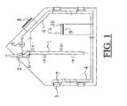
- Figure 1 shows an exemplary embodiment of the system according to the invention.
- FIG. 1 shows a building (e.g. a house) in which a ventilation system has been installed.
- the ventilation system includes air evacuation means in the form of a system of air ducts 1 via which air is drawn out of the various rooms of the building by a central fan 2. Fresh air can be admitted to the building via a non-central, non-forced, i.e. not provided with a fan or the like, air supply means in the form of supply openings 3.
- the installation also includes a liquid circuit 4 arranged for transferring thermal energy by circulation of a liquid.
- the liquid may be pumped in circulation by a pump 5.
- First temperature exchange means are formed by an air/liquid heat exchanger 6 that is arranged to exchange thermal energy from the air in the air exhaust means 1 and the liquid in the liquid circuit 4.
- air/liquid heat exchanger 6 that is arranged to exchange thermal energy from the air in the air exhaust means 1 and the liquid in the liquid circuit 4.
- Second temperature exchange means are formed by a number of air/liquid heat exchangers 7 that are arranged to exchange thermal energy from the air in the decentral air supply means 3 and the liquid in a liquid circuit 4.
- the relatively warm liquid can thus warm up the air originating from the outside to the inside of the building so that no cold draft is created and there is less need for "stoking" thanks to the heat recuperation.
- the relatively cold liquid can thus cool the air moving from the outside to the inside of the building so that the building requires less cooling.
- the liquid circuit 4 and the first and second temperature exchange means 6 and 7 respectively are therefore arranged such that the thermal energy of the air in the air evacuation means 1 and the thermal energy of the air in the decentral air supply means 3 respectively are mutually exchanged with high efficiency, so that the thermal energy - in the form of heat or cold (relative to the outside air) - can be recuperated.
- the pressure drop across the supply opening 3 including heat exchanger 7 on the air side may not be greater than ca. 1 Pa.
- FIG. 1 also shows that the means for heat extraction from the exhaust air can be supplemented by other sources of residual or ambient heat.
- solar collectors 8 may be connected to the liquid circuit 4 and/or heat exchangers 9 that are capable of recuperating from (warm) drainage water or wastewater, e.g. as shown schematically in the figure by a heat exchanger 9 that is connected to a shower tank 10.
Landscapes
- Engineering & Computer Science (AREA)
- Chemical & Material Sciences (AREA)
- Combustion & Propulsion (AREA)
- Mechanical Engineering (AREA)
- General Engineering & Computer Science (AREA)
- Life Sciences & Earth Sciences (AREA)
- Sustainable Development (AREA)
- Sustainable Energy (AREA)
- Building Environments (AREA)
Abstract
Ventilation system for houses, buildings etc. comprising air evacuation means (1,2) and decentral or central air supply means (3) such as façade grids etc. for forced or non-forced air supply. A transport circuit (4) with a pumpable medium such as a liquid, is arranged for transferring thermal energy by circulation of the medium. First temperature exchange means (6) are arranged to exchange thermal energy from one or more sources of residual or ambient heat, such as from the air in the air evacuation means (2), solar energy, or from wastewater, and the medium in the transport circuit. Second temperature exchange means (7) are arranged to exchange thermal energy between the air in the air supply means (3) and the medium in the transport circuit. The transport circuit (4) and the first and second temperature exchange means (6,7) are arranged such that the thermal energy of the sources of residual or ambient heat and the thermal energy of the air in the air supply means are mutually exchanged via the transport circuit.
Description
- The invention concerns a ventilation system for houses, buildings etc. comprising decentral or central air supply means such as façade grids etc. for forced or non-forced air supply.
- A large part of the dwellings in the Netherlands are equipped with a ventilation system with a forced (mechanical) central air exhaust and non-forced decentral air supply via façade grids etc.
- As presently arranged the system has the following disadvantages:
- it is impossible to recover useful heat without using a heat pump;
- pre-heating of the supply air, as in the case of balanced ventilation with heat recuperation, is not possible, because the supply grids are not centrally located;
- the installation of a balanced ventilation system in existing dwellings is problematic because of the dimensions of the supply ducts;
- the energy consumption of existing dwellings for the purpose of ventilation when outdoor temperatures are low is relatively high, and discomfort often occurs due to drafts from the air supply grids.
- It should be remarked that when "heat" recuperation is discussed, this may also be thought of "cold" recuperation (e.g., during hot seasons).
- The invention aims at counteracting the problems mentioned above by providing a ventilation system of the type discussed above, preferably by providing:
- a transportation circuit with a pumpable medium such as a liquid, arranged for transferring thermal energy by means of circulation of the medium;
- first temperature exchange means arranged to exchange thermal energy from one or more sources of residual or ambient heat - e.g. the air in the (central or non-central) air exhaust means, solar heat, heat in drain water or wastewater etc. - and the medium in the transportation circuit;
- second temperature exchange means arranged to exchange thermal energy between the air in the air supply means and the medium in the transportation circuit;
- the transport circuit and the first and second temperature exchange means being arranged such that the thermal energy of the sources of residual or ambient heat - whether previously stored or not - and the thermal energy of the air in the air supply means are exchanged via the transport circuit.
- The invention therefore aims at providing a system for harvesting or recuperating and (re)utilizing a great part of the residual or ambient heat (or cold) in dwellings and other buildings at low temperatures or at small temperature differences. The (residual or ambient) heat is extracted in particular from the ventilation exhaust air or possibly (also) from sources such as a solar panel, warm wastewater, flue gases, structural parts, the soil or temporary storage buffers. The high yield of heat recuperation has two causes. First the heat is transferred to the supply air. This is favorable because of the relatively low supply temperature. Second, a negative pressure prevails in buildings with a "C" ventilation system, i.e. a system having mechanical exhaust and natural supply, because of the forced evacuation of the air and the unforced ("natural") air supply (intake). This reduces the pressure difference across most leaks and therefore the total leakage flow so that the potential for heat recuperation from the ventilation exhaust air is maximal.
-
Figure 1 shows an exemplary embodiment of the system according to the invention. -
Figure 1 shows a building (e.g. a house) in which a ventilation system has been installed. The ventilation system includes air evacuation means in the form of a system ofair ducts 1 via which air is drawn out of the various rooms of the building by acentral fan 2. Fresh air can be admitted to the building via a non-central, non-forced, i.e. not provided with a fan or the like, air supply means in the form of supply openings 3. - The installation also includes a
liquid circuit 4 arranged for transferring thermal energy by circulation of a liquid. The liquid may be pumped in circulation by a pump 5. - First temperature exchange means are formed by an air/liquid heat exchanger 6 that is arranged to exchange thermal energy from the air in the air exhaust means 1 and the liquid in the
liquid circuit 4. In the cold season the relatively warm exhaust air originating from the (heated) building will warm up the liquid in theliquid circuit 4. During the warm season the relatively cold exhaust air originating from the (cooled) building will cool the liquid in theliquid circuit 4. - Second temperature exchange means are formed by a number of air/liquid heat exchangers 7 that are arranged to exchange thermal energy from the air in the decentral air supply means 3 and the liquid in a
liquid circuit 4. In the cold season the relatively warm liquid can thus warm up the air originating from the outside to the inside of the building so that no cold draft is created and there is less need for "stoking" thanks to the heat recuperation. In the warm season the relatively cold liquid can thus cool the air moving from the outside to the inside of the building so that the building requires less cooling. - The
liquid circuit 4 and the first and second temperature exchange means 6 and 7 respectively are therefore arranged such that the thermal energy of the air in the air evacuation means 1 and the thermal energy of the air in the decentral air supply means 3 respectively are mutually exchanged with high efficiency, so that the thermal energy - in the form of heat or cold (relative to the outside air) - can be recuperated. - In order not to interfere with the natural ventilation process the pressure drop across the supply opening 3 including heat exchanger 7 on the air side may not be greater than ca. 1 Pa.
-
Figure 1 also shows that the means for heat extraction from the exhaust air can be supplemented by other sources of residual or ambient heat. Thus, for example, solar collectors 8 may be connected to theliquid circuit 4 and/or heat exchangers 9 that are capable of recuperating from (warm) drainage water or wastewater, e.g. as shown schematically in the figure by a heat exchanger 9 that is connected to ashower tank 10.
Claims (4)
- Ventilation system for houses, buildings etc. comprising decentral or central air supply means (3) such as façade grids etc. for forced or non-forced air supply,
characterized by- a transport circuit with a pumpable medium such as a liquid arranged for transferring thermal energy by circulation of the medium;- first temperature exchange means (6,8,9) arranged to exchange thermal energy from one or more sources of residual or ambient heat and the medium in the transport circuit;- second temperature exchange means (7) arranged to exchange thermal energy between the air in the air supply means(3) and the medium in the transport circuit;- where the transport circuit (4) and the first and second temperature exchange means (6,7) are arranged such that the thermal energy from the sources of residual or ambient heat, stored or not-stored temporarily, and the thermal energy from the air in the air supply means are mutually exchanged via the transport circuit. - Ventilation system according to claim 1, comprising air evacuation means (1,2) and wherein the first temperature exchange means are arranged to exchange thermal energy in the air of the air evacuation means (1,2) and the medium in the transport circuit (4).
- Ventilation system according to claim 1, wherein the first temperature exchange means (8) are arranged to exchange thermal energy originating from the external environment of the relevant houses, buildings etc., such as solar energy, and the medium in the transport circuit (4).
- Ventilation system according to claim 1, wherein the first temperature exchange means (9) are arranged to exchange thermal energy from the inside of the relevant houses, buildings etc., such as present, e.g., in drainage water or wastewater and the medium in the transport circuit (4).
Priority Applications (2)
| Application Number | Priority Date | Filing Date | Title |
|---|---|---|---|
| EP07101434A EP1953467A1 (en) | 2007-01-30 | 2007-01-30 | Ventilation systems for houses, buildings, etc. |
| EP08150855A EP1970639A3 (en) | 2007-01-30 | 2008-01-30 | Ventilation system for houses, buildings etc. |
Applications Claiming Priority (1)
| Application Number | Priority Date | Filing Date | Title |
|---|---|---|---|
| EP07101434A EP1953467A1 (en) | 2007-01-30 | 2007-01-30 | Ventilation systems for houses, buildings, etc. |
Publications (1)
| Publication Number | Publication Date |
|---|---|
| EP1953467A1 true EP1953467A1 (en) | 2008-08-06 |
Family
ID=38051373
Family Applications (2)
| Application Number | Title | Priority Date | Filing Date |
|---|---|---|---|
| EP07101434A Withdrawn EP1953467A1 (en) | 2007-01-30 | 2007-01-30 | Ventilation systems for houses, buildings, etc. |
| EP08150855A Withdrawn EP1970639A3 (en) | 2007-01-30 | 2008-01-30 | Ventilation system for houses, buildings etc. |
Family Applications After (1)
| Application Number | Title | Priority Date | Filing Date |
|---|---|---|---|
| EP08150855A Withdrawn EP1970639A3 (en) | 2007-01-30 | 2008-01-30 | Ventilation system for houses, buildings etc. |
Country Status (1)
| Country | Link |
|---|---|
| EP (2) | EP1953467A1 (en) |
Cited By (3)
| Publication number | Priority date | Publication date | Assignee | Title |
|---|---|---|---|---|
| WO2013011351A1 (en) * | 2011-07-18 | 2013-01-24 | Phaza Energy Ltd. | Appartus and method for controlling a greenhouse environment |
| CN103206770A (en) * | 2013-01-10 | 2013-07-17 | 司永红 | Solar indoor air quick-cleaning system |
| BE1030564B1 (en) * | 2022-05-25 | 2024-01-03 | Patrick Brants | CLIMATE CONTROL SYSTEM FOR A BUILDING |
Families Citing this family (1)
| Publication number | Priority date | Publication date | Assignee | Title |
|---|---|---|---|---|
| CN104930676A (en) * | 2015-05-10 | 2015-09-23 | 长兴祯阳低碳热水系统有限公司 | Household air conditioning heat recovery energy saving device having PVT system |
Citations (5)
| Publication number | Priority date | Publication date | Assignee | Title |
|---|---|---|---|---|
| FR2336643A1 (en) * | 1975-12-22 | 1977-07-22 | Atomenergi Ab | HEAT TRANSFER INSTALLATION BETWEEN AN AIR OUTLET AND INTAKE |
| DE2843813A1 (en) * | 1978-10-07 | 1980-04-10 | Reinhold Laroche | Central heating system with duct for preheated air - uses cooling circuit with underground coil connected to heat exchanger in duct |
| DE19827511A1 (en) * | 1997-12-11 | 1999-06-24 | Fraunhofer Ges Forschung | Ventilation and heating energy supply system, with heat accumulator |
| DE10058273A1 (en) * | 2000-11-23 | 2002-05-29 | Woelfle Gmbh | Ventilator comprises heat pump unit, service and drinking water accumulator, heating water accumulator, electric heater, heat exchanger, closeable connections. |
| EP1698837A2 (en) * | 2005-02-23 | 2006-09-06 | Heinz Schilling KG | Heat recovery system with cold recovery during night time |
Family Cites Families (3)
| Publication number | Priority date | Publication date | Assignee | Title |
|---|---|---|---|---|
| DE20021331U1 (en) * | 2000-12-16 | 2001-05-23 | Kosack, Peter, Dr.-Ing., 67663 Kaiserslautern | Air conditioning system for residential buildings |
| US6948553B1 (en) * | 2002-10-09 | 2005-09-27 | Beutler Corporation | Modular heat recovery ventilation system |
| FR2899672A1 (en) * | 2006-04-07 | 2007-10-12 | Renault Sas | AIR CONDITIONING SYSTEM COMPRISING AN AIR PURIFYING DEVICE |
-
2007
- 2007-01-30 EP EP07101434A patent/EP1953467A1/en not_active Withdrawn
-
2008
- 2008-01-30 EP EP08150855A patent/EP1970639A3/en not_active Withdrawn
Patent Citations (5)
| Publication number | Priority date | Publication date | Assignee | Title |
|---|---|---|---|---|
| FR2336643A1 (en) * | 1975-12-22 | 1977-07-22 | Atomenergi Ab | HEAT TRANSFER INSTALLATION BETWEEN AN AIR OUTLET AND INTAKE |
| DE2843813A1 (en) * | 1978-10-07 | 1980-04-10 | Reinhold Laroche | Central heating system with duct for preheated air - uses cooling circuit with underground coil connected to heat exchanger in duct |
| DE19827511A1 (en) * | 1997-12-11 | 1999-06-24 | Fraunhofer Ges Forschung | Ventilation and heating energy supply system, with heat accumulator |
| DE10058273A1 (en) * | 2000-11-23 | 2002-05-29 | Woelfle Gmbh | Ventilator comprises heat pump unit, service and drinking water accumulator, heating water accumulator, electric heater, heat exchanger, closeable connections. |
| EP1698837A2 (en) * | 2005-02-23 | 2006-09-06 | Heinz Schilling KG | Heat recovery system with cold recovery during night time |
Cited By (4)
| Publication number | Priority date | Publication date | Assignee | Title |
|---|---|---|---|---|
| WO2013011351A1 (en) * | 2011-07-18 | 2013-01-24 | Phaza Energy Ltd. | Appartus and method for controlling a greenhouse environment |
| US9468158B2 (en) | 2011-07-18 | 2016-10-18 | Phaza Energy Ltd. | Apparatus and method for controlling a greenhouse environment |
| CN103206770A (en) * | 2013-01-10 | 2013-07-17 | 司永红 | Solar indoor air quick-cleaning system |
| BE1030564B1 (en) * | 2022-05-25 | 2024-01-03 | Patrick Brants | CLIMATE CONTROL SYSTEM FOR A BUILDING |
Also Published As
| Publication number | Publication date |
|---|---|
| EP1970639A3 (en) | 2010-07-07 |
| EP1970639A2 (en) | 2008-09-17 |
Similar Documents
| Publication | Publication Date | Title |
|---|---|---|
| MX2009003147A (en) | Active thermal energy storage system. | |
| US20110023517A1 (en) | Facility for producing sanitary hot water for congregate housing | |
| CN204948942U (en) | Warmhouse booth's temperature control system | |
| JP2012184912A (en) | Air conditioning device using underground heat | |
| EP1970639A2 (en) | Ventilation system for houses, buildings etc. | |
| FI125078B (en) | Method and arrangement for utilizing a low energy source in controlling the heat of the air in a utility room | |
| JP4936726B2 (en) | Geothermal air conditioning system | |
| JP3878636B2 (en) | Solar system house ventilation method | |
| JP2013163924A (en) | Building | |
| CN114711067B (en) | Integrated greenhouse thermal environment regulation and control system and method | |
| JP2008076015A (en) | Building air conditioning system using geothermal heat | |
| JP5911675B2 (en) | Air conditioning system operation method, air conditioning system construction method, and air conditioning system | |
| WO2017014345A1 (en) | System for recycling waste heat of hot waste water using hybrid cooling/heating device | |
| JP4866882B2 (en) | Underfloor heat storage system and underfloor heat storage method | |
| JP2006010170A (en) | Regional heat source system | |
| CN110285602A (en) | Shallow geothermal utilization equipment and utilization method for improving energy efficiency of ground source heat pumps | |
| EP2821714B1 (en) | Apparatus for heating a building | |
| WO2013089274A1 (en) | Smart ecological air-conditioning system | |
| CN113692861A (en) | Efficient cooling system for low-temperature grain storage of granary and working method of efficient cooling system | |
| RU75015U1 (en) | INSTALLATION FOR HEAT SUPPLY, COOLING AND VENTILATION OF PREMISES | |
| FR3064725B1 (en) | INSTALLATION FOR THE THERMAL REQUIREMENTS OF A SANITARY WATER BUILDING AND HEATING COMPRISING A THERMODYNAMIC HEATING | |
| CN101788188B (en) | Energy-saving stove | |
| JP2006084145A (en) | Underfloor ground heat utilizing natural heating method of house | |
| CN209950068U (en) | Heat energy recovery and utilization system | |
| FI20247126A1 (en) | Rooftop air heat pump for ventilation and method for implementing heat distribution |
Legal Events
| Date | Code | Title | Description |
|---|---|---|---|
| PUAI | Public reference made under article 153(3) epc to a published international application that has entered the european phase |
Free format text: ORIGINAL CODE: 0009012 |
|
| AK | Designated contracting states |
Kind code of ref document: A1 Designated state(s): AT BE BG CH CY CZ DE DK EE ES FI FR GB GR HU IE IS IT LI LT LU LV MC NL PL PT RO SE SI SK TR |
|
| AX | Request for extension of the european patent |
Extension state: AL BA HR MK RS |
|
| AKX | Designation fees paid | ||
| REG | Reference to a national code |
Ref country code: DE Ref legal event code: 8566 |
|
| STAA | Information on the status of an ep patent application or granted ep patent |
Free format text: STATUS: THE APPLICATION IS DEEMED TO BE WITHDRAWN |
|
| 18D | Application deemed to be withdrawn |
Effective date: 20090207 |