EP1950364A1 - Device for activating a bolt and door equipped with said device. - Google Patents
Device for activating a bolt and door equipped with said device. Download PDFInfo
- Publication number
- EP1950364A1 EP1950364A1 EP08100871A EP08100871A EP1950364A1 EP 1950364 A1 EP1950364 A1 EP 1950364A1 EP 08100871 A EP08100871 A EP 08100871A EP 08100871 A EP08100871 A EP 08100871A EP 1950364 A1 EP1950364 A1 EP 1950364A1
- Authority
- EP
- European Patent Office
- Prior art keywords
- bolt
- door
- opening
- electric actuator
- electromagnetic means
- Prior art date
- Legal status (The legal status is an assumption and is not a legal conclusion. Google has not performed a legal analysis and makes no representation as to the accuracy of the status listed.)
- Granted
Links
Images

Classifications
-
- E—FIXED CONSTRUCTIONS
- E05—LOCKS; KEYS; WINDOW OR DOOR FITTINGS; SAFES
- E05B—LOCKS; ACCESSORIES THEREFOR; HANDCUFFS
- E05B15/00—Other details of locks; Parts for engagement by bolts of fastening devices
- E05B15/10—Bolts of locks or night latches
- E05B15/101—Spring-retracted bolts
-
- E—FIXED CONSTRUCTIONS
- E05—LOCKS; KEYS; WINDOW OR DOOR FITTINGS; SAFES
- E05B—LOCKS; ACCESSORIES THEREFOR; HANDCUFFS
- E05B47/00—Operating or controlling locks or other fastening devices by electric or magnetic means
- E05B47/0001—Operating or controlling locks or other fastening devices by electric or magnetic means with electric actuators; Constructional features thereof
- E05B47/0002—Operating or controlling locks or other fastening devices by electric or magnetic means with electric actuators; Constructional features thereof with electromagnets
-
- E—FIXED CONSTRUCTIONS
- E05—LOCKS; KEYS; WINDOW OR DOOR FITTINGS; SAFES
- E05B—LOCKS; ACCESSORIES THEREFOR; HANDCUFFS
- E05B47/00—Operating or controlling locks or other fastening devices by electric or magnetic means
- E05B47/0001—Operating or controlling locks or other fastening devices by electric or magnetic means with electric actuators; Constructional features thereof
- E05B47/0012—Operating or controlling locks or other fastening devices by electric or magnetic means with electric actuators; Constructional features thereof with rotary electromotors
-
- E—FIXED CONSTRUCTIONS
- E05—LOCKS; KEYS; WINDOW OR DOOR FITTINGS; SAFES
- E05B—LOCKS; ACCESSORIES THEREFOR; HANDCUFFS
- E05B47/00—Operating or controlling locks or other fastening devices by electric or magnetic means
- E05B47/02—Movement of the bolt by electromagnetic means; Adaptation of locks, latches, or parts thereof, for movement of the bolt by electromagnetic means
- E05B47/026—Movement of the bolt by electromagnetic means; Adaptation of locks, latches, or parts thereof, for movement of the bolt by electromagnetic means the bolt moving rectilinearly
-
- E—FIXED CONSTRUCTIONS
- E05—LOCKS; KEYS; WINDOW OR DOOR FITTINGS; SAFES
- E05B—LOCKS; ACCESSORIES THEREFOR; HANDCUFFS
- E05B47/00—Operating or controlling locks or other fastening devices by electric or magnetic means
- E05B47/06—Controlling mechanically-operated bolts by electro-magnetically-operated detents
-
- E—FIXED CONSTRUCTIONS
- E05—LOCKS; KEYS; WINDOW OR DOOR FITTINGS; SAFES
- E05B—LOCKS; ACCESSORIES THEREFOR; HANDCUFFS
- E05B15/00—Other details of locks; Parts for engagement by bolts of fastening devices
- E05B15/0086—Toggle levers
-
- E—FIXED CONSTRUCTIONS
- E05—LOCKS; KEYS; WINDOW OR DOOR FITTINGS; SAFES
- E05B—LOCKS; ACCESSORIES THEREFOR; HANDCUFFS
- E05B15/00—Other details of locks; Parts for engagement by bolts of fastening devices
- E05B15/02—Striking-plates; Keepers; Bolt staples; Escutcheons
- E05B15/0205—Striking-plates, keepers, staples
-
- E—FIXED CONSTRUCTIONS
- E05—LOCKS; KEYS; WINDOW OR DOOR FITTINGS; SAFES
- E05B—LOCKS; ACCESSORIES THEREFOR; HANDCUFFS
- E05B17/00—Accessories in connection with locks
- E05B17/22—Means for operating or controlling lock or fastening device accessories, i.e. other than the fastening members, e.g. switches, indicators
-
- E—FIXED CONSTRUCTIONS
- E05—LOCKS; KEYS; WINDOW OR DOOR FITTINGS; SAFES
- E05B—LOCKS; ACCESSORIES THEREFOR; HANDCUFFS
- E05B47/00—Operating or controlling locks or other fastening devices by electric or magnetic means
- E05B47/0001—Operating or controlling locks or other fastening devices by electric or magnetic means with electric actuators; Constructional features thereof
- E05B2047/0014—Constructional features of actuators or power transmissions therefor
- E05B2047/0015—Output elements of actuators
- E05B2047/0016—Output elements of actuators with linearly reciprocating motion
-
- E—FIXED CONSTRUCTIONS
- E05—LOCKS; KEYS; WINDOW OR DOOR FITTINGS; SAFES
- E05B—LOCKS; ACCESSORIES THEREFOR; HANDCUFFS
- E05B47/00—Operating or controlling locks or other fastening devices by electric or magnetic means
- E05B2047/0072—Operation
- E05B2047/0076—Current to lock only, i.e. "fail-safe"
-
- E—FIXED CONSTRUCTIONS
- E05—LOCKS; KEYS; WINDOW OR DOOR FITTINGS; SAFES
- E05B—LOCKS; ACCESSORIES THEREFOR; HANDCUFFS
- E05B47/00—Operating or controlling locks or other fastening devices by electric or magnetic means
- E05B47/0001—Operating or controlling locks or other fastening devices by electric or magnetic means with electric actuators; Constructional features thereof
- E05B47/0002—Operating or controlling locks or other fastening devices by electric or magnetic means with electric actuators; Constructional features thereof with electromagnets
- E05B47/0006—Operating or controlling locks or other fastening devices by electric or magnetic means with electric actuators; Constructional features thereof with electromagnets having a non-movable core; with permanent magnet
Definitions
- the present invention relates to the field of electromechanical locks.
- It relates more particularly to a device for actuating a bolt, said bolt being movable in a translation movement in a direction between two extreme positions, a retracted position in which it is positioned inside said device and a projecting position in which it projects, at least partially, outside said device, said device comprising an electric actuator acting temporarily on said bolt to cause its passage from the retracted position to the projecting position, a return means acting permanently on said bolt to cause its passage from the projecting position to the retracted position, and an electromagnetic means holding said bolt in the projecting position when it is supplied with electric current.
- the direction of the translational movement of the bolt and the retaining direction of the electromagnet are thus parallel and even more precisely coaxial, that is to say, merged.
- Passive safety allows the locking of the bolt in the projecting position (and thus the locking of the door in the closed position) when the device, and more precisely the electromagnet, is supplied with electric current. It has the important advantage of causing the release of the door by removing the bolt under the effect of the return means during the power failure of the electromagnet.
- the "passive safety" devices to which belongs the present invention, can be used in the traditional way as an electric lock whose opening can be controlled remotely, and can also and above all be mounted as a safety device on doors emergency exits or service separating doors in buildings to allow free movement of persons in the absence of power, for example in case of fire.
- a major drawback of the device presented in the French patent application No. FR 2,653,480 is constituted by the fact that to meet the standards of resistance to the opening of the door, the electromagnet must be chosen very powerful. In addition to the fact that such electromagnets are expensive, they also require a lot of space because the coil must be oversized to provide the necessary boost.
- the electric motor system driving a worm is not practical because it requires “bring back" the worm to its starting position when the electromagnet begins to hold the bolt in the projecting position; it is thus necessary to provide end-of-travel contacts, but such elements do not always have the reliability required for a lock.
- the different standards in the countries provide that an electric lock can be operated at least 200 000 to 500 000 times without failure.
- the object of the invention is to overcome the drawbacks of the prior art by proposing a device for actuating a sufficiently strong bolt mechanically, while being sufficiently reliable and compact enough to be integrated into all openings or door frames and is also inexpensive.
- the present invention thus relates in its broadest sense to a device for actuating a bolt according to claim 1.
- the bolt is movable in a translation movement in a direction D between two extreme positions, a retracted position in which it is positioned inside a housing and a projecting position in which it projects, at least partially, outside said housing.
- the actuating device also comprises an electric actuator acting temporarily on said bolt to cause its passage from the retracted position to the projecting position, a return means acting permanently on said bolt to cause its passage from the projecting position to the position retracted, and an electromagnetic means retaining said bolt in the projecting position when it is supplied with electric current.
- the electromagnetic means has a retention direction D 'that is not parallel, and preferably perpendicular, to the direction D of the translational movement of said bolt.
- said electric actuator has a direction of action D "non-parallel, and preferably perpendicular to the first direction D of the translational movement of said bolt.
- the retaining direction D 'of the electromagnetic means and the direction of action D "of the electric actuator are parallel, without necessarily being confused in space.
- said electric actuator may, however, be positioned diametrically opposite to said electromagnetic means with respect to the direction D of the translational movement of said bolt.
- these directions D" and D' may not be identical in space; in this case, they are then shifted along the direction D of the translational movement of said bolt.
- the electric actuator is preferably an electric jack having a rod which is movable in the direction D "and towards the bolt under the effect of electrical pulses, it is thus not necessary to provide a complicated power supply. to make the transition from the retracted position to the projecting position, it could also be an electric motor or a solenoid.
- the device comprises a movable assembly comprising a pusher which is interposed between the electric actuator and the electromagnetic means, the latter two being thereby means independent of one another.
- This mobile assembly preferably comprises, in addition to the pusher, at least two rods mounted on transverse pins.
- the moving assembly is movable between a retained position in which it is retained by said electromagnetic means and a biased position in which it is recalled by said biasing means.
- the pusher of the movable assembly further preferably comprises, at one end a magnetic counterplate for cooperation with said electromagnetic means and at another end a base for cooperation with said electric actuator.
- the magnetic counter plate and the base are preferably parallel and positioned diametrically opposite to the direction D when the directions D 'and D "are also parallel and positioned diametrically opposite with respect to the direction D.
- the movable assembly further comprises, preferably, a guide rod mounted on pins.
- Said actuating device further comprises a striker having a recess accommodating said bolt.
- This recess preferably comprises at least one inclined wall having an angle ⁇ between 30 ° and 55 ° with respect to the direction D of the translation movement of said bolt.
- Such orientation of the wall allows the "force" opening of the door when, although the electromagnetic means is no longer supplied with electric current, a force is applied against the closed door (for example 1000 N) and s thus opposing the opening of the door (case of "panic” on the door) or in case of failure of the device (very unlikely but still possible case where although the electromagnetic means is no longer supplied the bolt does not not move to the retracted position); under the effect of a force evoked in the standards applied against the door in its opening direction, the bolt will thus forcefully retract by sliding along the inclined wall of the striker, until leaving the recess and thus cause the release of the door.
- the recess of the striker comprises two walls each having an angle ⁇ between 30 ° to 55 ° relative to the direction D of the translational movement of said bolt when it is desired that the door can open indifferently in both directions. 'opening.
- Said actuating device furthermore preferably comprises a strike presence sensor, to allow locking by the electromagnetic means only when the strike is actually positioned correctly to receive the bolt.
- the present invention also relates to a door having a frame and at least one opening, said door being equipped with at least one actuating device according to the invention at an upper horizontal edge and / or a song horizontal lower and / or a vertical edge of the opening and the frame.
- the present invention can thus be applied to two-opening doors cooperating with a single frame.
- the door is designed such that one of the opening can be opened only after the other, it suffices to provide the first opening opening of an actuating device; on the other hand, if the two doors can open independently of each other, it is preferable to provide the door with at least two actuating devices, each cooperating with an opening.
- the strike (where the strikes of each actuating device) of the door is (or are) positioned (s) in the edge of the opening (or openings).
- each actuating device is (or are) positioned in the edge of the frame.
- an opening or each opening of the door
- one (or more) keeper (s) according to the invention.
- the opening (or each opening of the door) is provided with two strikes, a striker being positioned on the upper horizontal edge of the opening and the other striker being positioned on the lower horizontal edge of the door.
- opening, the frame then being of course provided with two housings, a housing being positioned on the upper horizontal edge of the frame vis-à-vis the strike located there and the other housing being positioned on the lower horizontal edge of the frame vis-à-vis the strike located there.
- the device according to the invention makes it possible to carry out an access control by the door. Indeed, it allows to lock or not access to a specific room or to block a door that can serve as an emergency exit, this blocking occurs outside any emergency situation.
- the device according to the invention automatically releases the door as soon as the power supply of the electromagnetic means holding the bolt is cut off, under the effect of the return means.
- the device can be mounted in the frame of the door with a direction D of translation of the bolt vertical and / or horizontal.
- the device can be advantageously completely embedded in the frame and nothing is then visible from the outside when the door is closed.
- the device can be used for a double action door as for a single action door and can be powered in either 24V or 48V.
- the device Due to the need to provide a power supply and control cables, it is preferable to position the device in the door frame; however, because of its narrowness, the device can also be integrated in an opening, but then it is more difficult to conceal the power supply and control cables and they can then be subject to acts of vandalism.
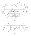
- the figure 1 illustrates a door (30) implementing an electromagnetic actuation device (1) according to the invention, illustrated in more detail on the figure 2 .
- This door (30) comprises an opening (32) and a frame (33), for example wood, aluminum, PVC or steel.
- the opening of course has two main faces and a peripheral edge, this singing co-operating in the lower part, upper and lateral with the frame for sealing the door because it is here a security door, especially a fire door, although the figure 1 does not illustrate one of the vertical cooperation nor the lower cooperation between the opening and the frame of the door.
- the door can be opened indifferently in one direction or the other.
- the actuating device consists on the one hand of a lock (2) having a housing (3) and a bolt (4) movable in a translational movement in a first direction D between two extreme positions, a retracted position in which it is positioned inside said housing (3) and a protruding position in which it projects, at least partially, outside said housing (3) and secondly with a striker (20) having a recess (21) disposed vis-à-vis the housing (3) and receiving said bolt (4) when in the projecting position.
- the housing (3) is integrated in the frame of the frame (33) in its upper part, so that the direction D is oriented in a vertical direction and that the bolt (4) can project beyond the upper horizontal edge (37) of the frame (33), downwards.
- the striker (20) it is integrated into the opening (32), in its upper part, so that it is not apparent on the main faces of the opening, but is only apparent at the upper horizontal edge (38) of the opening, without interfering with the cooperation between the opening and the frame at this location.
- the housing (3) also houses actuating means and in particular electromechanical means for the electromechanical locking of the opening vis-à-vis the frame in the closed position, this blocking being operated through the power supply means electromechanical.
- the device (1) thus presents electric cables (34) for the electromechanical power supply and for the passage of controls that are hidden in the frame and are thus not accessible to malicious acts.
- the door (30) further comprises two hinges (35, 36).
- the hinge (35) is here a spring hinge which causes the opening (32) to return to a closed door position as soon as it is no longer subjected to a manual opening force
- the hinge (36) is here a return damper hinge, for example a damping hinge with hydraulic braking, to control the speed of return of the leaf under the effect of the hinge spring. It is these two hinges that also transmit most of the weight of the opening (32) to the frame (33).
- the electric cables (34) are then accessible to malicious acts but any cut-off causing them to cut off the power supply of the electromechanical means will cause the interruption of the maintenance of the door in the closed position by the device (1) and will not oppose the opening movement of the opening in its opening direction, so as not to prevent evacuation.
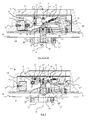
- FIGS. 2 and 3 illustrate an exemplary embodiment of an actuating device (1) according to the invention.
- the bolt (4) is in projecting position, to illustrate the cooperation between the latter and the striker (20).
- the bolt (4) is cylindrical and protrudes from the casing (3) in its direction of translation D by a circular hole (5) formed in a flat front (6) of the casing (3), substantially perpendicular to this facade. This hole is materialized by a circular ring.
- the front (6) is provided with holes (7, 7 ') for fixing the housing (3) to the frame so that the front (6) is flush with the edge (37) of the frame, as visible on the figure 4 .
- the casing (3) is also constituted by plates assembled with the front and protecting the actuating means. These plates, as well as the facade, are preferably metal and can be obtained by molding the housing or can be assembled by welding.
- the striker (20) has the general shape of a straight parallelepiped and the recess (21) opens at least on one of the faces of this parallelepiped: the face (22) intended to be positioned facing the facade ( 6) of the housing (3), flush with the edge (38) of the opening, as visible on the figure 4 .
- the recess (21) also opens on another side of the parallelepiped, the face (23), opposite the face (22).
- the striker (20) is provided with holes (27, 27 ') for attachment to the opening so that the face (22) is flush with the edge (38) of the opening.
- the striker (20) is preferably made of metal, but it can also be made of plastic. It can be manufactured by removal of material or by molding.
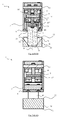
- the Figures 4 to 7 detail the contents of the actuating means housed by the casing (3) of the lock.
- the casing (3) thus comprises a movable assembly (8) composed of a longitudinal pusher (9) having at one end a magnetic plate (10) and at one end a base (10 '), as well as rods ( 14, 14 ', 16, 18) mounted on transverse pins (15, 15', 15 "; 17, 17 ').
- This assembly is actuated by an electric actuator (11) positioned inside the casing (3) and here constituted of a cylinder controlled electronically by a power supply, for example 24 V or 48 V (not shown).
- a power supply for example 24 V or 48 V (not shown).
- This electric actuator (11) is provided with a rod (11 ') movable in a direction of action D "not parallel to the first direction D of the translational movement of said bolt (4), the direction of action D" is here horizontal and thus perpendicular to the vertical direction D of the translation movement of the bolt (4).
- the moving assembly (8) can also be retained by electromagnetic means (13) when it is supplied with electric current.
- This means is here constituted by an electromagnetic suction cup (13) positioned inside the casing (3) and cooperating with the magnetic counterplate (10).
- the retention direction D 'of the electromagnetic means (13) is not parallel to the direction D of the translation movement of the bolt (4); the holding direction D 'is here horizontal and thus perpendicular to the vertical direction D.
- the retention direction D 'and the direction of action D are thus here parallel, without however being confused in space: they are shifted along the direction D by a distance of about 5 mm.
- the moving assembly (8) is also permanently under the influence of a return means (12) constituted by a coil spring tending to return the bolt (4) in the retracted position but which can also be a spring with a blade or any other possible return element.
- the spring is here stretched in a direction having an angle of about 50 ° with the direction D when the bolt (4) is in the projecting position and it is at rest, substantially horizontal, when the bolt (4) is in the retracted position .
- the bolt (4) is connected to the pusher (9) by means of the rods (14, 14 ', 18) and pins (15, 15', 15 "), more precisely and as otherwise visible in FIG. figure 6 the double link (14, 14 ') is rotatable at its upper end relative to the housing (3) around the pin (15) and the secondary link (18) is rotatable at its upper end relative to the the double rod (14, 14 ') around the pin (15') and at its lower end with respect to the bolt (4) around the pin (15 ").
- the links (14, 14 ', 18) are approximately aligned vertically, but when the bolt (4) is in the retracted position, as visible on the figure 5 only the pins (15, 15 ') remain aligned vertically; the pin (15 ') is pulled towards the actuator (11) under the effect of the return means attached to the base of the pusher; in doing so, the pusher (9) is also pulled towards the actuator (11) and slightly upwards under the effect of the return means to which it is linked.
- the pusher (9) is also connected at its other end to the plate against (10) by means of a fixing screw.
- the pusher (9) is further supported by a guide rod (16) and pins (17, 17 '). More precisely and as visible elsewhere in figure 7 , the link (16) is rotatable at its upper end relative to the housing (3) around the pin (17) and the pusher (9) is rotatable at the lower end of the link (16) around pin (17 ').
- the link (16) and the pins (17, 17 ') are optional insofar as they serve only for the reliable guidance of the pusher (9) and prevent play formation in the moving assembly (8). ).
- the width of the striker (20) may be substantially identical to the width of the facade (6): this is an important advantage of the invention; because of the moment of force created by the particular positioning of the electromagnetic lock and the use of the moving assembly, it is possible to use a sufficiently reliable electromagnetic lock while being compact.
- the latter solution where the proximal end (40) is slightly set back from the front (6), is preferable for reasons of reliability of guiding and mechanical maintenance.
- the recess (21) comprises two walls (25, 25 ') each having an angle ⁇ between 30 ° to 55 °, here of the order of 40 °, relative to the direction D of the translational movement of said bolt the door can open indifferently in both directions of opening.
- the presence of the opening is detected by means of a sensor (19) and the "presence of the opening" information is sent back to an electronic cell (not shown) by detection.
- the sensor (19) the presence of a magnet (24) located in the keeper (20) and flush with the face (21).
- the locking of the lock is done only by supplying the lock with electric current.
- the electronic cell will check the presence of the opening through the sensor (19) and the magnet (24). If the door is good present, the rod (11 ') of the electric cylinder automatically leaves under the effect of an electric pulse, to operate the pusher (9), to release the bolt (4), to stretch the return means (12) and gently bringing the magnetic backing plate (10) into contact with the electromagnetic lock (13). This being fed, the magnetic counterplate (10) thus comes to be firmly positioned against the electromagnetic lock (13) under the effect of the electromagnetic field, thus making it possible to lock the position of the pusher (9) and thus the bolt (4). ) in the housing (21) of the keeper (20) provided for this purpose.
- the lock is locked.
- the pusher is in the locked position, it actuates the positional contact (31) to return the information "lock locked” to the fire panel.
- the unlocking of the lock is obtained only by cutting the power supply, without sending any information that it self. Indeed, when there is a break in the current, the power supply of the electromagnet (13) is cut off and the electromagnetic field ceases to retain the counter plate (10) magnetic.
- the return means (12) "breaks” then the toggle formed by the rods (14, 14 '; 18), returns the pusher (9) to the initial position, guided by the rod (16), and the rod (11). ') of the electric cylinder to its initial position. By this action, the bolt (4) also returns to the initial position and the door is unlocked and free movement.
Abstract
Description
La présente invention se rapporte au domaine des serrures électromécaniques.The present invention relates to the field of electromechanical locks.
Elle concerne plus particulièrement un dispositif d'actionnement d'un pêne, ledit pêne étant mobile dans un mouvement de translation selon une direction entre deux positions extrêmes, une position rétractée dans laquelle il est positionné à l'intérieur dudit dispositif et une position saillante dans laquelle il fait saillit, au moins partiellement, à l'extérieur dudit dispositif, ledit dispositif comportant un actionneur électrique agissant temporairement sur ledit pêne pour provoquer son passage de la position rétractée à la position saillante, un moyen de rappel agissant en permanence sur ledit pêne pour provoquer son passage de la position saillante à la position rétractée, ainsi qu'un moyen électromagnétique retenant ledit pêne en position saillante lorsqu'il est alimenté en courant électrique.It relates more particularly to a device for actuating a bolt, said bolt being movable in a translation movement in a direction between two extreme positions, a retracted position in which it is positioned inside said device and a projecting position in which it projects, at least partially, outside said device, said device comprising an electric actuator acting temporarily on said bolt to cause its passage from the retracted position to the projecting position, a return means acting permanently on said bolt to cause its passage from the projecting position to the retracted position, and an electromagnetic means holding said bolt in the projecting position when it is supplied with electric current.
Il est connu de la demande de brevet français N°
La direction du mouvement de translation du pêne et la direction de retenue de l'électroaimant sont ainsi parallèles et même plus précisément coaxiales, c'est-à-dire confondues.The direction of the translational movement of the bolt and the retaining direction of the electromagnet are thus parallel and even more precisely coaxial, that is to say, merged.
De même, la direction d'action du moteur électrique et la direction de rappel du ressort sont coaxiales avec les précédentes.Likewise, the direction of action of the electric motor and the return direction of the spring are coaxial with the preceding ones.
Ce type de dispositif dit « à sécurité passive » permet le blocage du pêne en position saillante (et donc le blocage de la porte en position fermée) lorsque le dispositif, et plus précisément l'électroaimant, est alimenté en courant électrique. Il présente l'avantage important de provoquer la libération de la porte par retrait du pêne sous l'effet du moyen de rappel lors de la coupure de l'alimentation électrique de l'électroaimant.This type of device called "passive safety" allows the locking of the bolt in the projecting position (and thus the locking of the door in the closed position) when the device, and more precisely the electromagnet, is supplied with electric current. It has the important advantage of causing the release of the door by removing the bolt under the effect of the return means during the power failure of the electromagnet.
Il est également connu dans l'art antérieur des dispositifs dits « à sécurité active » dans lesquels c'est la coupure de l'alimentation électrique qui provoque le blocage du pêne en position saillante (et donc le blocage de la porte en position fermée). Toutefois, de tels dispositifs ne sont pas satisfaisants pour réaliser des issues de sécurité car lorsque l'alimentation électrique est coupée, - situation qui se produit souvent par exemple en cas d'incendie - il n'est plus possible d'évacuer par la porte ainsi bloquée, ce qui peut être très dangereux pour la survie des personnes concernées.It is also known in the prior art so-called devices "active safety" in which it is the power supply cut that causes the locking of the bolt in the projecting position (and therefore the locking of the door in the closed position) . However, such devices are not satisfactory to achieve safety issues because when the power is cut, - situation that often occurs for example in case of fire - it is no longer possible to evacuate through the door blocked, which can be very dangerous for the survival of the people concerned.
Les dispositifs « à sécurité passive », catégorie à laquelle appartient la présente invention, peuvent être utilisés de manière traditionnelle comme une serrure électrique dont l'ouverture peut être commandée à distance, et peuvent également et surtout être montés comme dispositif de sécurité sur les portes des issues de secours ou des portes de séparation de service dans les bâtiments pour permettre une libre circulation des personnes en l'absence de courant, par exemple en cas d'incendie.The "passive safety" devices, to which belongs the present invention, can be used in the traditional way as an electric lock whose opening can be controlled remotely, and can also and above all be mounted as a safety device on doors emergency exits or service separating doors in buildings to allow free movement of persons in the absence of power, for example in case of fire.
La gâche électrique présente ainsi deux états essentiels :
- soit elle est alimentée en courant électrique et la porte est ainsi bloquée en position fermée,
- soit elle n'est pas alimentée en courant et la porte peut être ouverte librement pour le libre passage des personnes.
- either it is supplied with electric current and the door is thus locked in the closed position,
- either it is not powered and the door can be opened freely for the free passage of people.
Un inconvénient majeur du dispositif présenté dans la demande de brevet français N°
Par ailleurs, le système de moteur électrique entraînant une vis sans fin n'est pas pratique car il nécessite de « ramener » la vis sans fin à sa position de départ lorsque l'électroaimant commence à retenir le pêne en position saillante ; il faut ainsi prévoir des contacts de fin de course, mais de tels éléments n'ont pas toujours la fiabilité requise pour une serrure. En effet, les différentes normes dans les pays prévoient qu'une serrure électrique puisse être actionnée au moins de 200 000 à 500 000 fois sans défaillance.Furthermore, the electric motor system driving a worm is not practical because it requires "bring back" the worm to its starting position when the electromagnet begins to hold the bolt in the projecting position; it is thus necessary to provide end-of-travel contacts, but such elements do not always have the reliability required for a lock. Indeed, the different standards in the countries provide that an electric lock can be operated at least 200 000 to 500 000 times without failure.
En outre, il se pose un problème de fiabilité de la serrure si la coupure électrique intervient alors que le pêne n'a pas encore été complètement rétracté : il risque d'être bloqué dans une position partiellement saillante qui risque d'empêcher l'ouverture de la porte.In addition, there is a problem of reliability of the lock if the power failure occurs while the bolt has not yet been fully retracted: it may be blocked in a partially protruding position that may prevent the opening Door.
Le but de l'invention est de pallier les inconvénients de l'art antérieur en proposant un dispositif d'actionnement d'un pêne suffisamment résistant mécaniquement, tout en étant suffisamment fiable et suffisamment compact pour pouvoir être intégré dans tous les ouvrants ou encadrement de porte et étant en outre peu onéreux.The object of the invention is to overcome the drawbacks of the prior art by proposing a device for actuating a sufficiently strong bolt mechanically, while being sufficiently reliable and compact enough to be integrated into all openings or door frames and is also inexpensive.
La présente invention se rapporte ainsi dans son acception la plus large à un dispositif d'actionnement d'un pêne selon la revendication 1.The present invention thus relates in its broadest sense to a device for actuating a bolt according to
Dans ce dispositif d'actionnement selon l'invention le pêne est mobile dans un mouvement de translation selon une direction D entre deux positions extrêmes, une position rétractée dans laquelle il est positionné à l'intérieur d'un carter et une position saillante dans laquelle il fait saillit, au moins partiellement, à l'extérieur dudit carter. Le dispositif d'actionnement comporte par ailleurs un actionneur électrique agissant temporairement sur ledit pêne pour provoquer son passage de la position rétractée à la position saillante, un moyen de rappel agissant en permanence sur ledit pêne pour provoquer son passage de la position saillante à la position rétractée, ainsi qu'un moyen électromagnétique retenant ledit pêne en position saillante lorsqu'il est alimenté en courant électrique.In this actuation device according to the invention the bolt is movable in a translation movement in a direction D between two extreme positions, a retracted position in which it is positioned inside a housing and a projecting position in which it projects, at least partially, outside said housing. The actuating device also comprises an electric actuator acting temporarily on said bolt to cause its passage from the retracted position to the projecting position, a return means acting permanently on said bolt to cause its passage from the projecting position to the position retracted, and an electromagnetic means retaining said bolt in the projecting position when it is supplied with electric current.
Le moyen électromagnétique présente une direction de retenue D' non parallèle, et de préférence perpendiculaire, à la direction D du mouvement de translation dudit pêne. Ainsi, en décalant la direction de retenue D' du moyen électromagnétique par rapport à la direction D du mouvement de translation dudit pêne un moment de force est crée, permettant de réduire la force de retenue nécessaire pour une retenue efficace du pêne par le moyen électromagnétique.The electromagnetic means has a retention direction D 'that is not parallel, and preferably perpendicular, to the direction D of the translational movement of said bolt. Thus, by shifting the retention direction D 'of the electromagnetic means with respect to the direction D of the translation movement of said bolt, a moment of force is created, making it possible to reduce the retaining force required for effective retention of the bolt by the electromagnetic means .
Cet effet de diminution de la force de retenue du moyen électromagnétique nécessaire se fait ressentir dès que la direction de retenue D' du moyen électromagnétique est décalée d'un angle d'au moins 5 ° par rapport à la direction D du mouvement de translation dudit pêne et plus cet angle est grand, plus la force de retenue du moyen électromagnétique nécessaire est petite à même effet de retenu final sur le pêne.This effect of decreasing the retaining force of the electromagnetic medium required is felt as soon as the retaining direction D 'of the electromagnetic means is shifted by an angle of at least 5 ° with respect to the direction D of the translation movement of said bolt and more this angle is large, the smaller the retaining force of the electromagnetic means is small to the same effect of final hold on the bolt.
Conséquemment, le moment de force est maximum, et la force de retenue nécessaire minimum, lorsque la direction de retenue D' est perpendiculaire à la direction D du mouvement de translation dudit pêne.Consequently, the moment of force is maximum, and the minimum necessary retaining force, when the retaining direction D 'is perpendicular to the direction D of the translation movement of said bolt.
La réduction de la force de retenue nécessaire dans le cas de l'invention permet alors, à force de retenue égale sur le pêne, d'utiliser un électroaimant moins puissant et par conséquent moins volumineux.The reduction of the retaining force required in the case of the invention then allows, by force of equal restraint on the bolt, to use a less powerful electromagnet and therefore less bulky.
Par ailleurs, ledit actionneur électrique présente une direction d'action D" non parallèle, et de préférence perpendiculaire, à la première direction D du mouvement de translation dudit pêne.Furthermore, said electric actuator has a direction of action D "non-parallel, and preferably perpendicular to the first direction D of the translational movement of said bolt.
Conséquemment également, le moment de force est maximum, et la force d'action nécessaire minimum, lorsque la direction d'action D" est perpendiculaire à la direction D du mouvement de translation dudit pêne.Consequently, also, the moment of force is maximum, and the minimum necessary action force, when the direction of action D "is perpendicular to the direction D of the translation movement of said bolt.
Dans une variante particulière, la direction de retenue D' du moyen électromagnétique et la direction d'action D" de l'actionneur électrique sont parallèles, sans forcément être confondues dans l'espace.In a particular variant, the retaining direction D 'of the electromagnetic means and the direction of action D "of the electric actuator are parallel, without necessarily being confused in space.
Dans cette variante, ledit actionneur électrique peut toutefois être positionné diamétralement opposé audit moyen électromagnétique par rapport à la direction D du mouvement de translation dudit pêne. Les directions D' et D" sont alors identiques dans l'espace.In this variant, said electric actuator may, however, be positioned diametrically opposite to said electromagnetic means with respect to the direction D of the translational movement of said bolt. The directions D 'and D "are then identical in space.
Toutefois, dans la variante où la direction d'action D" dudit actionneur électrique et la direction de retenue D' dudit moyen électromagnétique sont toutes les parallèles, ces directions D" et D' peuvent ne pas être identiques dans l'espace ; dans ce cas, elles sont alors décalées le long de la direction D du mouvement de translation dudit pêne.However, in the variant where the direction of action D "of said electric actuator and the retaining direction D 'of said electromagnetic means are all the parallels, these directions D" and D' may not be identical in space; in this case, they are then shifted along the direction D of the translational movement of said bolt.
L'actionneur électrique est, de préférence, un vérin électrique présentant une tige qui est mobile selon la direction D" et en direction du pêne sous l'effet d'impulsions électriques. Il n'est ainsi pas nécessaire de prévoir une alimentation électrique compliquée pour réaliser le passage de la position rétractée à la position saillante. Ce pourrait aussi être un moteur électrique ou un solénoïde.The electric actuator is preferably an electric jack having a rod which is movable in the direction D "and towards the bolt under the effect of electrical pulses, it is thus not necessary to provide a complicated power supply. to make the transition from the retracted position to the projecting position, it could also be an electric motor or a solenoid.
En outre, le dispositif comporte un ensemble mobile comportant un poussoir qui est intercalé entre l'actionneur électrique et le moyen électromagnétique, ces deux derniers étant de ce fait des moyens indépendants l'un de l'autre.In addition, the device comprises a movable assembly comprising a pusher which is interposed between the electric actuator and the electromagnetic means, the latter two being thereby means independent of one another.
Cet ensemble mobile comporte, de préférence, outre le poussoir, au moins deux biellettes montées sur des goupilles transversales.This mobile assembly preferably comprises, in addition to the pusher, at least two rods mounted on transverse pins.
L'ensemble mobile est mobile entre une position retenue dans laquelle il est retenu par ledit moyen électromagnétique et une position rappelée dans laquelle il est rappelé par ledit moyen de rappel.The moving assembly is movable between a retained position in which it is retained by said electromagnetic means and a biased position in which it is recalled by said biasing means.
Le poussoir de l'ensemble mobile comporte par ailleurs, de préférence, à une extrémité une contre plaque magnétique pour la coopération avec ledit moyen électromagnétique et à une autre extrémité une embase pour la coopération avec ledit actionneur électrique. La contre plaque magnétique et l'embase sont de préférences parallèles et positionnées diamétralement opposées par rapport à la direction D lorsque les directions D' et D" sont elles aussi parallèles et positionnées diamétralement opposées par rapport à la direction D.The pusher of the movable assembly further preferably comprises, at one end a magnetic counterplate for cooperation with said electromagnetic means and at another end a base for cooperation with said electric actuator. The magnetic counter plate and the base are preferably parallel and positioned diametrically opposite to the direction D when the directions D 'and D "are also parallel and positioned diametrically opposite with respect to the direction D.
L'ensemble mobile comporte en outre, de préférence, une biellette de guidage montée sur des goupilles.The movable assembly further comprises, preferably, a guide rod mounted on pins.
Ledit dispositif d'actionnement comporte par ailleurs une gâche comportant un évidement accueillant ledit pêne.Said actuating device further comprises a striker having a recess accommodating said bolt.
Cet évidement comporte, de préférence, au moins une paroi inclinée présentant un angle α entre 30 ° à 55 ° par rapport à la direction D du mouvement de translation dudit pêne. Une telle orientation de la paroi permet l'ouverture « de force » de la porte lorsque, bien que le moyen électromagnétique ne soit plus alimenté en courant électrique, une force est appliquée contre la porte fermée (par exemple de 1 000 N) et s'opposant ainsi à l'ouverture de la porte (cas de « panique » sur la porte) ou alors en cas de défaillance du dispositif (cas très improbable mais tout de même possible où bien que le moyen électromagnétique ne soit plus alimenté le pêne ne passe pas en position rétractée) ; sous l'effet d'une force évoquée dans les normes appliquée contre la porte dans son sens d'ouverture, le pêne va ainsi se rétracter de force en glissant le long de la paroi inclinée de la gâche, jusqu'à quitter l'évidement et provoquer ainsi la libération de la porte.This recess preferably comprises at least one inclined wall having an angle α between 30 ° and 55 ° with respect to the direction D of the translation movement of said bolt. Such orientation of the wall allows the "force" opening of the door when, although the electromagnetic means is no longer supplied with electric current, a force is applied against the closed door (for example 1000 N) and s thus opposing the opening of the door (case of "panic" on the door) or in case of failure of the device (very unlikely but still possible case where although the electromagnetic means is no longer supplied the bolt does not not move to the retracted position); under the effect of a force evoked in the standards applied against the door in its opening direction, the bolt will thus forcefully retract by sliding along the inclined wall of the striker, until leaving the recess and thus cause the release of the door.
L'évidement de la gâche comporte deux parois présentant chacune un angle α entre 30 ° à 55 ° par rapport à la direction D du mouvement de translation dudit pêne lorsqu'il est souhaité que la porte puisse s'ouvrir indifféremment dans les deux sens d'ouverture.The recess of the striker comprises two walls each having an angle α between 30 ° to 55 ° relative to the direction D of the translational movement of said bolt when it is desired that the door can open indifferently in both directions. 'opening.
Ledit dispositif d'actionnement comporte en outre, de préférence, un capteur de présence de la gâche, pour permettre un verrouillage par le moyen électromagnétique uniquement lorsque la gâche est effectivement positionnée correctement pour accueillir le pêne.Said actuating device furthermore preferably comprises a strike presence sensor, to allow locking by the electromagnetic means only when the strike is actually positioned correctly to receive the bolt.
La présente invention se rapporte également à une porte présentant un encadrement et au moins un ouvrant, ladite porte étant équipée d'au moins un dispositif d'actionnement selon l'invention au niveau d'un chant horizontal supérieur et/ou d'un chant horizontal inférieur et/ou d'un chant vertical de l'ouvrant et de l'encadrement.The present invention also relates to a door having a frame and at least one opening, said door being equipped with at least one actuating device according to the invention at an upper horizontal edge and / or a song horizontal lower and / or a vertical edge of the opening and the frame.
Dans le cas où la porte est munie de plusieurs dispositifs d'actionnement selon l'invention, leur action est bien sûr coordonnée à l'aide de moyens de contrôle électriques adéquats.In the case where the door is provided with several actuating devices according to the invention, their action is of course coordinated by means of adequate electrical control means.
La présente invention peut ainsi s'appliquer au cas des portes à deux ouvrants coopérant avec un encadrement unique. Dans le cas où la porte est conçue de telle manière qu'un des ouvrant ne peut être ouvert qu'après l'autre, il suffit de munir l'ouvrant s'ouvrant en premier d'un dispositif d'actionnement ; par contre, si les deux ouvrants peuvent s'ouvrir indépendamment l'un de l'autre, il est préférable de munir la porte d'au moins deux dispositifs d'actionnement, chacun coopérant avec un ouvrant.The present invention can thus be applied to two-opening doors cooperating with a single frame. In the case where the door is designed such that one of the opening can be opened only after the other, it suffices to provide the first opening opening of an actuating device; on the other hand, if the two doors can open independently of each other, it is preferable to provide the door with at least two actuating devices, each cooperating with an opening.
Dans une utilisation préférée de l'invention, la gâche (où les gâches de chaque dispositif d'actionnement) de la porte est (ou sont) positionnée(s) dans le chant de l'ouvrant (ou des ouvrants).In a preferred use of the invention, the strike (where the strikes of each actuating device) of the door is (or are) positioned (s) in the edge of the opening (or openings).
Ce qui signifie que le carter (ou les carters) de chaque dispositif d'actionnement est (ou sont) positionné(s) dans le chant de l'encadrement.This means that the housing (or casings) of each actuating device is (or are) positioned in the edge of the frame.
Il est ainsi possible de prévoir qu'un ouvrant (ou que chaque ouvrant de la porte) soit muni d'une (ou de plusieurs) gâche(s) selon l'invention.It is thus possible to provide that an opening (or each opening of the door) is provided with one (or more) keeper (s) according to the invention.
Dans une variante toute particulière, l'ouvrant (ou chaque ouvrant de la porte) est muni de deux gâches, une gâche étant positionnée sur le chant horizontal supérieur de l'ouvrant et l'autre gâche étant positionnée sur le chant horizontal inférieur de l'ouvrant, l'encadrement étant alors bien sûr muni de deux carters, un carter étant positionné sur le chant horizontal supérieur de l'encadrement en vis-à-vis de la gâche située à cet endroit et l'autre carter étant positionné sur le chant horizontal inférieur de l'encadrement en vis-à-vis de la gâche située à cet endroit.In a very particular variant, the opening (or each opening of the door) is provided with two strikes, a striker being positioned on the upper horizontal edge of the opening and the other striker being positioned on the lower horizontal edge of the door. opening, the frame then being of course provided with two housings, a housing being positioned on the upper horizontal edge of the frame vis-à-vis the strike located there and the other housing being positioned on the lower horizontal edge of the frame vis-à-vis the strike located there.
Avantageusement, le dispositif selon l'invention permet de réaliser un contrôle d'accès par la porte. En effet, il permet de verrouiller ou non l'accès à un local spécifique ou de bloquer une porte pouvant servir d'issue de secours, ce blocage s'opérant en dehors de tout situation de secours.Advantageously, the device according to the invention makes it possible to carry out an access control by the door. Indeed, it allows to lock or not access to a specific room or to block a door that can serve as an emergency exit, this blocking occurs outside any emergency situation.
Avantageusement également, en situation de secours, le dispositif selon l'invention permet de libérer automatiquement la porte dès que l'alimentation électrique du moyen électromagnétique retenant le pêne est coupée, sous l'effet du moyen de rappel.Advantageously also, in emergency situation, the device according to the invention automatically releases the door as soon as the power supply of the electromagnetic means holding the bolt is cut off, under the effect of the return means.
Avantageusement également, le dispositif peut être monté dans l'huisserie de la porte avec une direction D de translation du pêne verticale et/ou horizontale. Le dispositif peut être avantageusement complètement encastrée dans l'huisserie et rien n'est alors visible de l'extérieur lorsque la porte est fermée.Advantageously also, the device can be mounted in the frame of the door with a direction D of translation of the bolt vertical and / or horizontal. The device can be advantageously completely embedded in the frame and nothing is then visible from the outside when the door is closed.
Le dispositif peut être utilisé pour une porte double action comme pour une porte simple action et peut être alimentée soit en 24V soit en 48V.The device can be used for a double action door as for a single action door and can be powered in either 24V or 48V.
Du fait de la nécessite de prévoir une alimentation électrique et des câbles de commande, il est préférable de positionner le dispositif dans l'huisserie de la porte ; toutefois, du fait de son étroitesse, le dispositif peut aussi être intégré dans un ouvrant, mais alors il est plus difficile de dissimuler l'alimentation électrique et les câbles de commande et ces derniers peuvent alors être sujets à des actes de vandalisme.Due to the need to provide a power supply and control cables, it is preferable to position the device in the door frame; however, because of its narrowness, the device can also be integrated in an opening, but then it is more difficult to conceal the power supply and control cables and they can then be subject to acts of vandalism.
La présente invention sera mieux comprise à la lecture de la description détaillée ci-après d'exemples de réalisation non limitatifs et des figures ci-jointes :
- La
figure 1 illustre une vue partielle en perspective d'une porte à un seul ouvrant et à double sens d'ouverture, la porte étant équipée d'un dispositif d'actionnement selon l'invention ; - La
figure 2 illustre une vue en perspective d'un dispositif d'actionnement selon l'invention ; - La
figure 3 illustre une vue de dessus du dispositif d'actionnement de lafigure 2 ; - La
figure 4 illustre une vue en coupe transversale selon A-A du dispositif d'actionnement de lafigure 3 , intégré dans une porte, le pêne du dispositif étant en position saillante ; - La
figure 5 illustre une vue en coupe transversale similaire à celle de lafigure 4 , le pêne du dispositif étant toutefois en position rétractée ; - La
figure 6 illustre une vue en coupe selon B-B du dispositif d'actionnement de lafigure 4 , sans la porte ; - La
figure 7 illustre une vue en coupe selon C-C du dispositif d'actionnement de lafigure 4 , sans la porte.
- The
figure 1 illustrates a partial perspective view of a door to a single opening and double opening direction, the door being equipped with an actuating device according to the invention; - The
figure 2 illustrates a perspective view of an actuating device according to the invention; - The
figure 3 illustrates a view from above of the actuating device of thefigure 2 ; - The
figure 4 illustrates a cross-sectional view along AA of the actuating device of thefigure 3 integrated in a door, the bolt of the device being in the projecting position; - The
figure 5 illustrates a cross-sectional view similar to that of thefigure 4 , the bolt of the device being however in the retracted position; - The
figure 6 illustrates a sectional view along BB of the actuating device of thefigure 4 without the door; - The
figure 7 illustrates a sectional view along CC of the actuating device of thefigure 4 , without the door.
Il est précisé que dans ces figures les proportions entre les divers éléments représentés ne sont pas rigoureusement respectées et les éléments de coupe en arrière plan ne sont pas toujours représentés, afin d'en faciliter la lecture.It is specified that in these figures the proportions between the various elements represented are not rigorously respected and the cutting elements in the background are not always represented, in order to facilitate reading.
La
Cette porte (30) comporte un ouvrant (32) ainsi qu'un encadrement (33), par exemple en bois, en aluminium, en PVC ou en acier. L'ouvrant présente bien sûr deux faces principales ainsi qu'un chant périphérique, ce chant coopérant en partie inférieure, supérieure et latérale avec l'encadrement pour une fermeture étanche de la porte car il s'agit ici d'une porte de sécurité, en particulier une porte coupe-feu, bien que la
La porte peut être ouverte indifféremment dans un sens ou dans l'autre.The door can be opened indifferently in one direction or the other.
Le dispositif d'actionnement est constitué d'une part d'une serrure (2) comportant un carter (3) et un pêne (4) mobile dans un mouvement de translation selon une première direction D entre deux positions extrêmes, une position rétractée dans laquelle il est positionné à l'intérieur dudit carter (3) et une position saillante dans laquelle il fait saillit, au moins partiellement, à l'extérieur dudit carter (3) et d'autre part d'une gâche (20) comportant un évidement (21) disposé en vis-à-vis du carter (3) et accueillant ledit pêne (4) lorsqu'il est en position saillante.The actuating device consists on the one hand of a lock (2) having a housing (3) and a bolt (4) movable in a translational movement in a first direction D between two extreme positions, a retracted position in which it is positioned inside said housing (3) and a protruding position in which it projects, at least partially, outside said housing (3) and secondly with a striker (20) having a recess (21) disposed vis-à-vis the housing (3) and receiving said bolt (4) when in the projecting position.
Dans la configuration illustrée sur la
Le carter (3) abrite par ailleurs des moyens d'actionnement et en particulier des moyens électromécaniques pour le blocage électromécanique de l'ouvrant vis-à-vis du dormant en position fermée, ce blocage étant opéré grâce à l'alimentation électrique de moyens électromécaniques.The housing (3) also houses actuating means and in particular electromechanical means for the electromechanical locking of the opening vis-à-vis the frame in the closed position, this blocking being operated through the power supply means electromechanical.
Le dispositif (1) présente ainsi des câbles électriques (34) pour l'alimentation électrique des moyens électromécaniques et pour le passage des commandes qui sont dissimulés dans le dormant et ne sont ainsi pas accessibles aux actes de malveillance.The device (1) thus presents electric cables (34) for the electromechanical power supply and for the passage of controls that are hidden in the frame and are thus not accessible to malicious acts.
La porte (30) comporte par ailleurs deux charnières (35, 36). La charnière (35) est ici une charnière ressort qui provoque le retour de l'ouvrant (32) dans une position porte fermée dès qu'il n'est plus soumis à une force d'ouverture manuelle, et la charnière (36) est ici une charnière amortisseur de retour, par exemple une charnière amortisseur à freinage hydraulique, permettant de maîtriser la vitesse de retour de l'ouvrant sous l'effet de la charnière ressort. Ce sont ces deux charnières qui transmettent par ailleurs en majeure partie le poids de l'ouvrant (32) à l'encadrement (33).The door (30) further comprises two hinges (35, 36). The hinge (35) is here a spring hinge which causes the opening (32) to return to a closed door position as soon as it is no longer subjected to a manual opening force, and the hinge (36) is here a return damper hinge, for example a damping hinge with hydraulic braking, to control the speed of return of the leaf under the effect of the hinge spring. It is these two hinges that also transmit most of the weight of the opening (32) to the frame (33).
D'autres configurations sont bien sûr possibles :
- La porte peut ne pas être une porte de sécurité et la coopération entre l'ouvrant et l'encadrement peut ne pas être sur toute la périphérie de l'ouvrant mais sur une partie seulement ;
- la porte peut être à sens d'ouverture unique ;
- le retour de la porte en position fermée peut être opérée par un pivot à retour de porte à amortissement hydraulique ou par un ferme-porte à amortissement hydraulique ;
- le dispositif (1) peut être positionné au niveau des chants verticaux de l'ouvrant et du dormant, par exemple à proximité d'une poignée ;
- la serrure peut être intégrée dans un chant de l'ouvrant et la gâche peut alors être intégrée dans un chant du dormant ; ...
- The door may not be a security door and the cooperation between the opening and the frame may not be on the whole periphery of the opening but on only one part;
- the door can be in a single opening direction;
- the return of the door in the closed position can be operated by a hydraulically damped door return pivot or by a hydraulic damping door closer;
- the device (1) can be positioned at the vertical edges of the opening and the frame, for example near a handle;
- the lock can be integrated in a song of the opening and the striker can then be integrated into a song of the frame; ...
Toutefois, dans ce dernier cas, les câbles électriques (34) sont alors accessibles aux actes de malveillance mais toute coupure de ces derniers entraînant la coupure de l'alimentation électrique des moyens électromécaniques va provoquer l'interruption du maintien de la porte en position fermée par le dispositif (1) et ne va donc pas s'opposer au mouvement d'ouverture de l'ouvrant selon son sens d'ouverture, afin de ne pas empêcher l'évacuation.However, in the latter case, the electric cables (34) are then accessible to malicious acts but any cut-off causing them to cut off the power supply of the electromechanical means will cause the interruption of the maintenance of the door in the closed position by the device (1) and will not oppose the opening movement of the opening in its opening direction, so as not to prevent evacuation.
Les
Sur cette figure, le pêne (4) est en position saillante, afin d'illustrer la coopération entre ce dernier et la gâche (20).In this figure, the bolt (4) is in projecting position, to illustrate the cooperation between the latter and the striker (20).
Le pêne (4) est cylindrique et fait sailli du carter (3) selon sa direction de translation D par un trou (5) circulaire ménagé dans une façade (6) plate du carter (3), sensiblement perpendiculairement à cette façade. Ce trou est matérialisé par une bague circulaire.The bolt (4) is cylindrical and protrudes from the casing (3) in its direction of translation D by a circular hole (5) formed in a flat front (6) of the casing (3), substantially perpendicular to this facade. This hole is materialized by a circular ring.
La façade (6) est munie de trous (7, 7') pour la fixation du carter (3) à l'encadrement de telle sorte que la façade (6) soit affleurante avec le chant (37) de l'encadrement, comme visible sur la
Le carter (3) est par ailleurs constitué de plaques assemblées avec la façade et protégeant les moyens d'actionnement. Ces plaques, ainsi que la façade, sont, de préférence, en métal et peuvent être obtenues par moulage du carter ou peuvent être assemblées par soudage.The casing (3) is also constituted by plates assembled with the front and protecting the actuating means. These plates, as well as the facade, are preferably metal and can be obtained by molding the housing or can be assembled by welding.
La gâche (20) présente une forme générale de parallélépipède droit et l'évidement (21) débouche au moins sur une des faces de ce parallélépipède : la face (22), destinées à être positionnées en vis-à-vis de la façade (6) du carter (3), affleurante avec le chant (38) de l'ouvrant, comme visible sur la
Dans la version illustrée en
La gâche (20) est munie de trous (27, 27') pour sa fixation à l'ouvrant de telle sorte que la face (22) soit affleurante avec le chant (38) de l'ouvrant.The striker (20) is provided with holes (27, 27 ') for attachment to the opening so that the face (22) is flush with the edge (38) of the opening.
La gâche (20) est, de préférence, en métal, mais elle peut aussi être en matière plastique. Elle peut-être fabriquée par enlèvement de matière ou par moulage.The striker (20) is preferably made of metal, but it can also be made of plastic. It can be manufactured by removal of material or by molding.
Les
Cet ensemble est actionné par un actionneur électrique (11) positionné à l'intérieur du carter (3) et constitué ici d'un vérin commandé de façon électronique par une alimentation électrique, par exemple en 24 V ou en 48V (non illustrée).This assembly is actuated by an electric actuator (11) positioned inside the casing (3) and here constituted of a cylinder controlled electronically by a power supply, for example 24 V or 48 V (not shown).
Cet actionneur électrique (11) est muni d'une tige (11') mobile selon une direction d'action D" non parallèle à la première direction D du mouvement de translation dudit pêne (4) ; la direction d'action D" est ici horizontale et ainsi perpendiculaire à la direction D verticale du mouvement de translation du pêne (4).This electric actuator (11) is provided with a rod (11 ') movable in a direction of action D "not parallel to the first direction D of the translational movement of said bolt (4), the direction of action D" is here horizontal and thus perpendicular to the vertical direction D of the translation movement of the bolt (4).
L'ensemble mobile (8) peut par ailleurs être retenu par un moyen électromagnétique (13) lorsqu'il est alimenté en courant électrique. Ce moyen est constitué ici d'une ventouse électromagnétique (13) positionnée à l'intérieur du carter (3) et coopérant avec la contre plaque magnétique (10).The moving assembly (8) can also be retained by electromagnetic means (13) when it is supplied with electric current. This means is here constituted by an electromagnetic suction cup (13) positioned inside the casing (3) and cooperating with the magnetic counterplate (10).
Comme visible sur la
La direction de retenue D' et la direction d'action D" sont donc ainsi ici parallèles, sans être toutefois confondues dans l'espace : elles sont décalées le long de la direction D d'une distance d'environ 5 mm.The retention direction D 'and the direction of action D "are thus here parallel, without however being confused in space: they are shifted along the direction D by a distance of about 5 mm.
L'ensemble mobile (8) est par ailleurs en permanence sous l'influence d'un moyen de rappel (12) constitué ici d'un ressort hélicoïdal tendant à ramener le pêne (4) en position rétractée mais qui peut être également un ressort à lame ou tout autre élément de rappel possible. Le ressort est ainsi ici tendu selon une direction présentant un angle d'environ 50 ° avec la direction D lorsque le pêne (4) est en position saillante et il est au repos, sensiblement horizontal, lorsque le pêne (4) est en position rétractée.The moving assembly (8) is also permanently under the influence of a return means (12) constituted by a coil spring tending to return the bolt (4) in the retracted position but which can also be a spring with a blade or any other possible return element. The spring is here stretched in a direction having an angle of about 50 ° with the direction D when the bolt (4) is in the projecting position and it is at rest, substantially horizontal, when the bolt (4) is in the retracted position .
Le pêne (4) est lié au poussoir (9) par le biais des biellettes (14, 14' ; 18) et des goupilles (15, 15', 15"). Plus précisément et comme visible par ailleurs en
Comme visible sur la
Il est à noter que l'embase du poussoir (9) n'est pas liée à l'actionneur (11).It should be noted that the base of the pusher (9) is not connected to the actuator (11).
Le poussoir (9) est par ailleurs lié à son autre extrémité à la contre plaque (10) par le biais d'une vis de fixation.The pusher (9) is also connected at its other end to the plate against (10) by means of a fixing screw.
La comparaison des
La comparaison des
Ce positionnement particulier favorise une coopération mécanique adéquate entre les différents éléments, assurant un transfert efficace des efforts sans provoquer d'usure prématurée au niveau des contacts mécaniques.This particular positioning promotes an adequate mechanical cooperation between the various elements, ensuring efficient transfer of forces without causing premature wear in the mechanical contacts.
Le poussoir (9) est par ailleurs soutenu par une biellette (16) de guidage et des goupilles (17, 17'). Plus précisément et comme visible par ailleurs en
La biellette (16) et les goupilles (17, 17') sont facultatives dans la mesure où elles ne servent qu'au guidage fiable du poussoir (9) et empêchent la formation de jeu à l'usage dans l'ensemble mobile (8).The link (16) and the pins (17, 17 ') are optional insofar as they serve only for the reliable guidance of the pusher (9) and prevent play formation in the moving assembly (8). ).
Comme visible sur la
Comme visible sur la
Ainsi, au sens de la présente invention, lorsqu'il est expliqué qu'en position saillante le pêne (4) fait sailli à l'extérieur du carter (3), il faut comprendre que dans cette position il peut être complètement à l'extérieur du carter (3) de telle sorte que son extrémité proximale (40) soit au-delà de la façade (6) si les moyens qui le portent le permettent, ou que l'extrémité proximale (40) peut être affleurante avec la façade (6) ou encore que l'extrémité proximale (40) peut être légèrement en retrait de la façade (6), tout en permettant, dans cette position saillante, au pêne (4) d'entrer en contact et de coopérer avec la gâche (20).Thus, within the meaning of the present invention, when it is explained that in projecting position the bolt (4) protrudes outside the housing (3), it should be understood that in this position it can be completely at the outside the casing (3) so that its proximal end (40) is beyond the front (6) if the means that carry it allow, or that the proximal end (40) can be flush with the facade (6) or that the proximal end (40) can be slightly set back from the front (6), while allowing, in this projecting position , to the bolt (4) to come into contact and cooperate with the striker (20).
Comme expliqué précédemment, cette dernière solution, où l'extrémité proximale (40) est légèrement en retrait de la façade (6), est préférable pour des raisons de fiabilité du guidage et du maintien mécanique.As explained above, the latter solution, where the proximal end (40) is slightly set back from the front (6), is preferable for reasons of reliability of guiding and mechanical maintenance.
Comme visible sur la
Ainsi, au sens de la présente invention, lorsqu'il est expliqué qu'en position rétractée le pêne (4) est positionné à l'intérieur du carter (3), il faut comprendre que dans cette position il peut être complètement à l'intérieur du carter (3) de telle sorte que son extrémité distale (41) soit en retrait par rapport à la façade (6), ou que l'extrémité distale (41) peut être affleurante avec la façade (6) ou encore que l'extrémité distale (41) peut saillir légèrement au delà de la façade (6) sans toutefois pouvoir entrer en contact ou coopérer avec la gâche (20).Thus, in the sense of the present invention, when it is explained that in the retracted position the bolt (4) is positioned inside the housing (3), it should be understood that in this position it can be completely at the inside the housing (3) so that its distal end (41) is recessed with respect to the front (6), or that the distal end (41) can be flush with the front (6) or that the the distal end (41) can protrude slightly beyond the front (6) without however being able to come into contact with or cooperate with the striker (20).
Comme visible par ailleurs sur la
Ces parois permettent une ouverture « de force » de la porte sous l'effet d'un effort important, répondant aux normes : sous l'effet de cette force, si le moyen électromagnétique (13) n'est plus alimenté en courant mais que le pêne (4) n'est pas en position rétractée, le pêne va entrer en contact avec une des parois et glisser le long de cette paroi jusqu'à sortir de l'évidement (21), libérant de ce fait l'ouvrant.These walls allow a "force" opening of the door under the effect of a significant effort, meeting the standards: under the effect of this force, if the electromagnetic means (13) is no longer supplied with current but that the bolt (4) is not in the retracted position, the bolt will come into contact with one of the walls and slide along this wall until it comes out of the recess (21), thereby releasing the opening.
Pour actionner le dispositif, il y a détection de la présence de l'ouvrant par l'intermédiaire d'un capteur (19) et l'information « présence de l'ouvrant » est renvoyée à une cellule électronique (non illustrée) par détection par le capteur (19) de la présence d'un aimant (24) situé dans la gâche (20) et affleurant au niveau de la face (21).To actuate the device, the presence of the opening is detected by means of a sensor (19) and the "presence of the opening" information is sent back to an electronic cell (not shown) by detection. by the sensor (19) the presence of a magnet (24) located in the keeper (20) and flush with the face (21).
Le verrouillage de la serrure se fait uniquement en alimentant la serrure en courant électrique. Lorsque la serrure est alimentée, la cellule électronique va vérifier la présence de l'ouvrant par le biais du capteur (19) et de l'aimant (24). Si la porte est bien présente, la tige (11') du vérin électrique sort automatiquement sous l'effet d'une impulsion électrique, afin de manoeuvrer le poussoir (9), de sortir le pêne (4), de tendre le moyen de rappel (12) et d'amener doucement la contre plaque magnétique (10) en contact avec la ventouse électromagnétique (13). Celle-ci étant alimentée, la contre plaque (10) magnétique vient donc se positionner fermement contre la ventouse électromagnétique (13) sous l'effet du champ électromagnétique, permettant ainsi de verrouiller la position du poussoir (9) et donc le pêne (4) dans le logement (21) de la gâche (20) prévu à cet effet.The locking of the lock is done only by supplying the lock with electric current. When the lock is powered, the electronic cell will check the presence of the opening through the sensor (19) and the magnet (24). If the door is good present, the rod (11 ') of the electric cylinder automatically leaves under the effect of an electric pulse, to operate the pusher (9), to release the bolt (4), to stretch the return means (12) and gently bringing the magnetic backing plate (10) into contact with the electromagnetic lock (13). This being fed, the magnetic counterplate (10) thus comes to be firmly positioned against the electromagnetic lock (13) under the effect of the electromagnetic field, thus making it possible to lock the position of the pusher (9) and thus the bolt (4). ) in the housing (21) of the keeper (20) provided for this purpose.
La serrure est alors verrouillée.The lock is locked.
Le poussoir étant en position verrouillée, il actionne le contact de position (31) permettant de renvoyer l'information « serrure verrouillée » à la centrale incendie.The pusher is in the locked position, it actuates the positional contact (31) to return the information "lock locked" to the fire panel.
Le déverrouillage de la serrure s'obtient seulement en coupant l'alimentation électrique, sans envoi d'aucune information que ce soi. En effet, lorsqu'il y a rupture du courant, l'alimentation de la ventouse électromagnétique (13) est coupée et le champ électromagnétique cesse de retenir la contre plaque (10) magnétique.The unlocking of the lock is obtained only by cutting the power supply, without sending any information that it self. Indeed, when there is a break in the current, the power supply of the electromagnet (13) is cut off and the electromagnetic field ceases to retain the counter plate (10) magnetic.
Le moyen de rappel (12) « casse » alors la genouillère formée par les biellettes (14, 14' ; 18), ramène le poussoir (9) en position initiale, guidé par la biellette (16), ainsi que la tige (11') du vérin électrique à sa position initiale. Par cette action, le pêne (4) revient également en position initiale et la porte est déverrouillée et libre de mouvement.The return means (12) "breaks" then the toggle formed by the rods (14, 14 '; 18), returns the pusher (9) to the initial position, guided by the rod (16), and the rod (11). ') of the electric cylinder to its initial position. By this action, the bolt (4) also returns to the initial position and the door is unlocked and free movement.
La présente invention est décrite dans ce qui précède à titre d'exemple. Il est entendu que l'homme du métier est à même de réaliser différentes variantes de l'invention sans pour autant sortir du cadre du brevet tel que défini par les revendications.The present invention is described in the foregoing by way of example. It is understood that the skilled person is able to achieve different variants of the invention without departing from the scope of the patent as defined by the claims.
Claims (12)
Applications Claiming Priority (1)
| Application Number | Priority Date | Filing Date | Title |
|---|---|---|---|
| FR0752887A FR2911898B1 (en) | 2007-01-25 | 2007-01-25 | PEN ACTUATING DEVICE AND DOOR EQUIPPED WITH SAID DEVICE. |
Publications (2)
| Publication Number | Publication Date |
|---|---|
| EP1950364A1 true EP1950364A1 (en) | 2008-07-30 |
| EP1950364B1 EP1950364B1 (en) | 2013-12-18 |
Family
ID=38456549
Family Applications (1)
| Application Number | Title | Priority Date | Filing Date |
|---|---|---|---|
| EP08100871.6A Active EP1950364B1 (en) | 2007-01-25 | 2008-01-24 | Device for activating a bolt and door equipped with said device |
Country Status (2)
| Country | Link |
|---|---|
| EP (1) | EP1950364B1 (en) |
| FR (1) | FR2911898B1 (en) |
Cited By (5)
| Publication number | Priority date | Publication date | Assignee | Title |
|---|---|---|---|---|
| EP2594713A2 (en) | 2011-11-21 | 2013-05-22 | ASSA ABLOY Sicherheitstechnik GmbH | Door opener |
| DE102013001020A1 (en) | 2012-08-10 | 2014-02-13 | Assa Abloy Sicherheitstechnik Gmbh | glass door opener |
| EP2706174A3 (en) * | 2012-09-05 | 2017-04-19 | DORMA Deutschland GmbH | Lock for a door |
| US10316549B2 (en) * | 2012-05-11 | 2019-06-11 | Bqt Solutions (Sea) Pte Limited | Lock |
| US20230407677A1 (en) * | 2022-06-15 | 2023-12-21 | Hanchett Entry System, Inc. | Modular surface mounted electric strike |
Families Citing this family (1)
| Publication number | Priority date | Publication date | Assignee | Title |
|---|---|---|---|---|
| CN117716099A (en) * | 2021-07-21 | 2024-03-15 | 亚萨合莱澳洲有限公司 | Electromechanical articulated latch |
Citations (5)
| Publication number | Priority date | Publication date | Assignee | Title |
|---|---|---|---|---|
| US4099752A (en) * | 1975-07-08 | 1978-07-11 | Geringer Arthur V | Electric lock |
| FR2653480A1 (en) | 1989-10-25 | 1991-04-26 | Vincenti Henri | Electric lock with automatic spring opening |
| FR2695426A1 (en) * | 1992-09-10 | 1994-03-11 | Aldes Aeraulique | Electrically-operated, remotely controlled door-lock - has door secured by spring-loaded bolt, retained electromagnetically, and reset, after release, by reclosure of door. |
| DE4344266A1 (en) * | 1992-12-31 | 1994-09-01 | Ebs Gmbh Elektronische Banksys | Locking system for furniture |
| DE9413062U1 (en) * | 1994-08-12 | 1994-12-15 | Reiners Christa | bars |
-
2007
- 2007-01-25 FR FR0752887A patent/FR2911898B1/en active Active
-
2008
- 2008-01-24 EP EP08100871.6A patent/EP1950364B1/en active Active
Patent Citations (5)
| Publication number | Priority date | Publication date | Assignee | Title |
|---|---|---|---|---|
| US4099752A (en) * | 1975-07-08 | 1978-07-11 | Geringer Arthur V | Electric lock |
| FR2653480A1 (en) | 1989-10-25 | 1991-04-26 | Vincenti Henri | Electric lock with automatic spring opening |
| FR2695426A1 (en) * | 1992-09-10 | 1994-03-11 | Aldes Aeraulique | Electrically-operated, remotely controlled door-lock - has door secured by spring-loaded bolt, retained electromagnetically, and reset, after release, by reclosure of door. |
| DE4344266A1 (en) * | 1992-12-31 | 1994-09-01 | Ebs Gmbh Elektronische Banksys | Locking system for furniture |
| DE9413062U1 (en) * | 1994-08-12 | 1994-12-15 | Reiners Christa | bars |
Cited By (10)
| Publication number | Priority date | Publication date | Assignee | Title |
|---|---|---|---|---|
| EP2594713A2 (en) | 2011-11-21 | 2013-05-22 | ASSA ABLOY Sicherheitstechnik GmbH | Door opener |
| DE102012111085A1 (en) | 2011-11-21 | 2013-05-23 | Assa Abloy Sicherheitstechnik Gmbh | Door Opener |
| DE102012111085B4 (en) * | 2011-11-21 | 2015-11-05 | Assa Abloy Sicherheitstechnik Gmbh | Door Opener |
| EP2594713A3 (en) * | 2011-11-21 | 2017-11-29 | ASSA ABLOY Sicherheitstechnik GmbH | Door opener |
| US10316549B2 (en) * | 2012-05-11 | 2019-06-11 | Bqt Solutions (Sea) Pte Limited | Lock |
| DE102013001020A1 (en) | 2012-08-10 | 2014-02-13 | Assa Abloy Sicherheitstechnik Gmbh | glass door opener |
| WO2014023787A2 (en) | 2012-08-10 | 2014-02-13 | Assa Abloy Sicherheitstechnik Gmbh | Glass-door opener |
| EP2706174A3 (en) * | 2012-09-05 | 2017-04-19 | DORMA Deutschland GmbH | Lock for a door |
| US20230407677A1 (en) * | 2022-06-15 | 2023-12-21 | Hanchett Entry System, Inc. | Modular surface mounted electric strike |
| US11885154B2 (en) * | 2022-06-15 | 2024-01-30 | Hanchett Entry Systems, Inc. | Modular surface mounted electric strike |
Also Published As
| Publication number | Publication date |
|---|---|
| FR2911898A1 (en) | 2008-08-01 |
| EP1950364B1 (en) | 2013-12-18 |
| FR2911898B1 (en) | 2019-06-07 |
Similar Documents
| Publication | Publication Date | Title |
|---|---|---|
| EP1950364B1 (en) | Device for activating a bolt and door equipped with said device | |
| FR2868111A1 (en) | IMPROVEMENTS RELATING TO MAGNETIC LATCHES | |
| EP0178362A1 (en) | Remotely controlled device for locking and unlocking, particularly for an anti-panic bar | |
| EP0015857A1 (en) | Device for the motorized opening and closing of a gate | |
| EP0928870B1 (en) | Espagnolette or espagnolette-lock for door, window-door or the same | |
| EP2868842B1 (en) | Device for locking a swimming-pool cover in an extended position | |
| EP1404605A1 (en) | Device for locking a lift door with independent emergency unlocking | |
| FR2749606A1 (en) | DEVICE FOR LOCKING RELATIVE MOVEMENT OF TWO ORDERS RELATIVE TO EACH OTHER, ESPECIALLY FOR REMOVABLE WALL BRACKETS, CASHROOM DOORS, CANDELABRING PORTILONS OR OTHER | |
| CA2552919C (en) | Serrure electromagnetique a pene escamotable pour porte battante | |
| FR2954396A1 (en) | Window/door aperture closing device i.e. roller shutter, for dwelling, has movable part displaced with respect to fixed part for separating edge of panel from fixed part, after unlocking of movable part and after exertion of force on panel | |
| FR2591270A1 (en) | Electrically-operated fire protection door | |
| EP2230372B1 (en) | Security entry lock | |
| FR2845109A1 (en) | Lock for door or letter box lid has linkage fixed to lid panel and with manually operated bolt to which electric actuator is connected | |
| FR2621349A1 (en) | Electromagnetic device for keeping an opening panel in the closed position | |
| EP0396471A1 (en) | Electrical locking device, unlocked by cutting off the current, adapted to emergency-exits | |
| FR2941987A1 (en) | Adjustable striker plate for use in bolt actuating device for e.g. electrical lock of rotational door, in building, has recess comprising tubular wall and base that is movable with respect to tubular wall along central axis to wall and base | |
| FR3071269B1 (en) | ELECTROMAGNETIC LOCKING DOOR CLOSURE ASSEMBLY | |
| FR2866980A1 (en) | Electric safety device for e.g. garage door lock, has circuit breaker with shunt composed of metal plate, and electrical contacts that are retracted or moved when door is in open and closed positions, respectively | |
| FR2959525A1 (en) | Device for securing exterior doorset in room, has servo mechanism that is arranged such that opening or closing pivoting movement of clapper that drives opening or closing pivoting movement of another clapper | |
| WO2022053746A1 (en) | Closure system consisting of a pin tumbler lock with twist-lock serving as a switch to one or more electric locks and this or these electric locks | |
| EP2660414B1 (en) | Security access lock device | |
| FR2796751A1 (en) | Electromagnetic striker for locks comprises bead attached to core and restraining removal of polar plate when solenoid is active, and allowing its removal when solenoid is not active | |
| EP2586938A2 (en) | Device for locking an openable wing | |
| FR2650024A1 (en) | Device for locking and unlocking an emergency exit | |
| EP2246505A1 (en) | Lock with a moveable bolt, lockable with a toggle-lever |
Legal Events
| Date | Code | Title | Description |
|---|---|---|---|
| PUAI | Public reference made under article 153(3) epc to a published international application that has entered the european phase |
Free format text: ORIGINAL CODE: 0009012 |
|
| 17P | Request for examination filed |
Effective date: 20080124 |
|
| AK | Designated contracting states |
Kind code of ref document: A1 Designated state(s): AT BE BG CH CY CZ DE DK EE ES FI FR GB GR HR HU IE IS IT LI LT LU LV MC MT NL NO PL PT RO SE SI SK TR |
|
| AX | Request for extension of the european patent |
Extension state: AL BA MK RS |
|
| AKX | Designation fees paid |
Designated state(s): AT BE BG CH CY CZ DE DK EE ES FI FR GB GR HR HU IE IS IT LI LT LU LV MC MT NL NO PL PT RO SE SI SK TR |
|
| GRAP | Despatch of communication of intention to grant a patent |
Free format text: ORIGINAL CODE: EPIDOSNIGR1 |
|
| INTG | Intention to grant announced |
Effective date: 20130416 |
|
| GRAP | Despatch of communication of intention to grant a patent |
Free format text: ORIGINAL CODE: EPIDOSNIGR1 |
|
| INTG | Intention to grant announced |
Effective date: 20130701 |
|
| GRAS | Grant fee paid |
Free format text: ORIGINAL CODE: EPIDOSNIGR3 |
|
| GRAA | (expected) grant |
Free format text: ORIGINAL CODE: 0009210 |
|
| RIN1 | Information on inventor provided before grant (corrected) |
Inventor name: GRILLOT, XAVIER |
|
| AK | Designated contracting states |
Kind code of ref document: B1 Designated state(s): AT BE BG CH CY CZ DE DK EE ES FI FR GB GR HR HU IE IS IT LI LT LU LV MC MT NL NO PL PT RO SE SI SK TR |
|
| REG | Reference to a national code |
Ref country code: GB Ref legal event code: FG4D Free format text: NOT ENGLISH |
|
| REG | Reference to a national code |
Ref country code: CH Ref legal event code: EP |
|
| REG | Reference to a national code |
Ref country code: AT Ref legal event code: REF Ref document number: 645733 Country of ref document: AT Kind code of ref document: T Effective date: 20140115 |
|
| REG | Reference to a national code |
Ref country code: IE Ref legal event code: FG4D Free format text: LANGUAGE OF EP DOCUMENT: FRENCH |
|
| REG | Reference to a national code |
Ref country code: DE Ref legal event code: R096 Ref document number: 602008029351 Country of ref document: DE Effective date: 20140213 |
|
| REG | Reference to a national code |
Ref country code: NL Ref legal event code: VDEP Effective date: 20131218 |
|
| PG25 | Lapsed in a contracting state [announced via postgrant information from national office to epo] |
Ref country code: LT Free format text: LAPSE BECAUSE OF FAILURE TO SUBMIT A TRANSLATION OF THE DESCRIPTION OR TO PAY THE FEE WITHIN THE PRESCRIBED TIME-LIMIT Effective date: 20131218 Ref country code: NO Free format text: LAPSE BECAUSE OF FAILURE TO SUBMIT A TRANSLATION OF THE DESCRIPTION OR TO PAY THE FEE WITHIN THE PRESCRIBED TIME-LIMIT Effective date: 20140318 Ref country code: SE Free format text: LAPSE BECAUSE OF FAILURE TO SUBMIT A TRANSLATION OF THE DESCRIPTION OR TO PAY THE FEE WITHIN THE PRESCRIBED TIME-LIMIT Effective date: 20131218 Ref country code: HR Free format text: LAPSE BECAUSE OF FAILURE TO SUBMIT A TRANSLATION OF THE DESCRIPTION OR TO PAY THE FEE WITHIN THE PRESCRIBED TIME-LIMIT Effective date: 20131218 Ref country code: FI Free format text: LAPSE BECAUSE OF FAILURE TO SUBMIT A TRANSLATION OF THE DESCRIPTION OR TO PAY THE FEE WITHIN THE PRESCRIBED TIME-LIMIT Effective date: 20131218 |
|
| REG | Reference to a national code |
Ref country code: AT Ref legal event code: MK05 Ref document number: 645733 Country of ref document: AT Kind code of ref document: T Effective date: 20131218 |
|
| REG | Reference to a national code |
Ref country code: LT Ref legal event code: MG4D |
|
| PG25 | Lapsed in a contracting state [announced via postgrant information from national office to epo] |
Ref country code: LV Free format text: LAPSE BECAUSE OF FAILURE TO SUBMIT A TRANSLATION OF THE DESCRIPTION OR TO PAY THE FEE WITHIN THE PRESCRIBED TIME-LIMIT Effective date: 20131218 |
|
| BERE | Be: lapsed |
Owner name: SAINT-GOBAIN SEVA Effective date: 20140131 Owner name: GRILLOT, XAVIER Effective date: 20140131 |
|
| PG25 | Lapsed in a contracting state [announced via postgrant information from national office to epo] |
Ref country code: IS Free format text: LAPSE BECAUSE OF FAILURE TO SUBMIT A TRANSLATION OF THE DESCRIPTION OR TO PAY THE FEE WITHIN THE PRESCRIBED TIME-LIMIT Effective date: 20140418 Ref country code: EE Free format text: LAPSE BECAUSE OF FAILURE TO SUBMIT A TRANSLATION OF THE DESCRIPTION OR TO PAY THE FEE WITHIN THE PRESCRIBED TIME-LIMIT Effective date: 20131218 |
|
| PG25 | Lapsed in a contracting state [announced via postgrant information from national office to epo] |
Ref country code: CZ Free format text: LAPSE BECAUSE OF FAILURE TO SUBMIT A TRANSLATION OF THE DESCRIPTION OR TO PAY THE FEE WITHIN THE PRESCRIBED TIME-LIMIT Effective date: 20131218 Ref country code: AT Free format text: LAPSE BECAUSE OF FAILURE TO SUBMIT A TRANSLATION OF THE DESCRIPTION OR TO PAY THE FEE WITHIN THE PRESCRIBED TIME-LIMIT Effective date: 20131218 Ref country code: CY Free format text: LAPSE BECAUSE OF FAILURE TO SUBMIT A TRANSLATION OF THE DESCRIPTION OR TO PAY THE FEE WITHIN THE PRESCRIBED TIME-LIMIT Effective date: 20131218 Ref country code: NL Free format text: LAPSE BECAUSE OF FAILURE TO SUBMIT A TRANSLATION OF THE DESCRIPTION OR TO PAY THE FEE WITHIN THE PRESCRIBED TIME-LIMIT Effective date: 20131218 Ref country code: LU Free format text: LAPSE BECAUSE OF FAILURE TO SUBMIT A TRANSLATION OF THE DESCRIPTION OR TO PAY THE FEE WITHIN THE PRESCRIBED TIME-LIMIT Effective date: 20140124 Ref country code: SK Free format text: LAPSE BECAUSE OF FAILURE TO SUBMIT A TRANSLATION OF THE DESCRIPTION OR TO PAY THE FEE WITHIN THE PRESCRIBED TIME-LIMIT Effective date: 20131218 Ref country code: ES Free format text: LAPSE BECAUSE OF FAILURE TO SUBMIT A TRANSLATION OF THE DESCRIPTION OR TO PAY THE FEE WITHIN THE PRESCRIBED TIME-LIMIT Effective date: 20131218 Ref country code: PL Free format text: LAPSE BECAUSE OF FAILURE TO SUBMIT A TRANSLATION OF THE DESCRIPTION OR TO PAY THE FEE WITHIN THE PRESCRIBED TIME-LIMIT Effective date: 20131218 Ref country code: RO Free format text: LAPSE BECAUSE OF FAILURE TO SUBMIT A TRANSLATION OF THE DESCRIPTION OR TO PAY THE FEE WITHIN THE PRESCRIBED TIME-LIMIT Effective date: 20131218 Ref country code: PT Free format text: LAPSE BECAUSE OF FAILURE TO SUBMIT A TRANSLATION OF THE DESCRIPTION OR TO PAY THE FEE WITHIN THE PRESCRIBED TIME-LIMIT Effective date: 20140418 |
|
| REG | Reference to a national code |
Ref country code: CH Ref legal event code: PL |
|
| REG | Reference to a national code |
Ref country code: DE Ref legal event code: R097 Ref document number: 602008029351 Country of ref document: DE |
|
| PG25 | Lapsed in a contracting state [announced via postgrant information from national office to epo] |
Ref country code: MC Free format text: LAPSE BECAUSE OF FAILURE TO SUBMIT A TRANSLATION OF THE DESCRIPTION OR TO PAY THE FEE WITHIN THE PRESCRIBED TIME-LIMIT Effective date: 20131218 |
|
| PLBE | No opposition filed within time limit |
Free format text: ORIGINAL CODE: 0009261 |
|
| STAA | Information on the status of an ep patent application or granted ep patent |
Free format text: STATUS: NO OPPOSITION FILED WITHIN TIME LIMIT |
|
| PG25 | Lapsed in a contracting state [announced via postgrant information from national office to epo] |
Ref country code: DK Free format text: LAPSE BECAUSE OF FAILURE TO SUBMIT A TRANSLATION OF THE DESCRIPTION OR TO PAY THE FEE WITHIN THE PRESCRIBED TIME-LIMIT Effective date: 20131218 Ref country code: LI Free format text: LAPSE BECAUSE OF NON-PAYMENT OF DUE FEES Effective date: 20140131 Ref country code: CH Free format text: LAPSE BECAUSE OF NON-PAYMENT OF DUE FEES Effective date: 20140131 |
|
| REG | Reference to a national code |
Ref country code: IE Ref legal event code: MM4A |
|
| 26N | No opposition filed |
Effective date: 20140919 |
|
| GBPC | Gb: european patent ceased through non-payment of renewal fee |
Effective date: 20140318 |
|
| REG | Reference to a national code |
Ref country code: DE Ref legal event code: R097 Ref document number: 602008029351 Country of ref document: DE Effective date: 20140919 |
|
| PG25 | Lapsed in a contracting state [announced via postgrant information from national office to epo] |
Ref country code: GB Free format text: LAPSE BECAUSE OF NON-PAYMENT OF DUE FEES Effective date: 20140318 Ref country code: IE Free format text: LAPSE BECAUSE OF NON-PAYMENT OF DUE FEES Effective date: 20140124 Ref country code: BE Free format text: LAPSE BECAUSE OF NON-PAYMENT OF DUE FEES Effective date: 20140131 |
|
| PG25 | Lapsed in a contracting state [announced via postgrant information from national office to epo] |
Ref country code: SI Free format text: LAPSE BECAUSE OF FAILURE TO SUBMIT A TRANSLATION OF THE DESCRIPTION OR TO PAY THE FEE WITHIN THE PRESCRIBED TIME-LIMIT Effective date: 20131218 |
|
| REG | Reference to a national code |
Ref country code: FR Ref legal event code: PLFP Year of fee payment: 9 |
|
| PG25 | Lapsed in a contracting state [announced via postgrant information from national office to epo] |
Ref country code: MT Free format text: LAPSE BECAUSE OF FAILURE TO SUBMIT A TRANSLATION OF THE DESCRIPTION OR TO PAY THE FEE WITHIN THE PRESCRIBED TIME-LIMIT Effective date: 20131218 |
|
| PG25 | Lapsed in a contracting state [announced via postgrant information from national office to epo] |
Ref country code: BG Free format text: LAPSE BECAUSE OF FAILURE TO SUBMIT A TRANSLATION OF THE DESCRIPTION OR TO PAY THE FEE WITHIN THE PRESCRIBED TIME-LIMIT Effective date: 20131218 |
|
| PG25 | Lapsed in a contracting state [announced via postgrant information from national office to epo] |
Ref country code: GR Free format text: LAPSE BECAUSE OF FAILURE TO SUBMIT A TRANSLATION OF THE DESCRIPTION OR TO PAY THE FEE WITHIN THE PRESCRIBED TIME-LIMIT Effective date: 20140319 Ref country code: IT Free format text: LAPSE BECAUSE OF FAILURE TO SUBMIT A TRANSLATION OF THE DESCRIPTION OR TO PAY THE FEE WITHIN THE PRESCRIBED TIME-LIMIT Effective date: 20131218 |
|
| PG25 | Lapsed in a contracting state [announced via postgrant information from national office to epo] |
Ref country code: HU Free format text: LAPSE BECAUSE OF FAILURE TO SUBMIT A TRANSLATION OF THE DESCRIPTION OR TO PAY THE FEE WITHIN THE PRESCRIBED TIME-LIMIT; INVALID AB INITIO Effective date: 20080124 Ref country code: TR Free format text: LAPSE BECAUSE OF FAILURE TO SUBMIT A TRANSLATION OF THE DESCRIPTION OR TO PAY THE FEE WITHIN THE PRESCRIBED TIME-LIMIT Effective date: 20131218 |
|
| REG | Reference to a national code |
Ref country code: FR Ref legal event code: PLFP Year of fee payment: 10 |
|
| REG | Reference to a national code |
Ref country code: FR Ref legal event code: PLFP Year of fee payment: 11 |
|
| PGFP | Annual fee paid to national office [announced via postgrant information from national office to epo] |
Ref country code: FR Payment date: 20230130 Year of fee payment: 16 |
|
| PGFP | Annual fee paid to national office [announced via postgrant information from national office to epo] |
Ref country code: DE Payment date: 20221130 Year of fee payment: 16 |