EP1950352A2 - Flood protection system - Google Patents
Flood protection system Download PDFInfo
- Publication number
- EP1950352A2 EP1950352A2 EP08000903A EP08000903A EP1950352A2 EP 1950352 A2 EP1950352 A2 EP 1950352A2 EP 08000903 A EP08000903 A EP 08000903A EP 08000903 A EP08000903 A EP 08000903A EP 1950352 A2 EP1950352 A2 EP 1950352A2
- Authority
- EP
- European Patent Office
- Prior art keywords
- shaft
- wall
- protection device
- flood protection
- buoyancy
- Prior art date
- Legal status (The legal status is an assumption and is not a legal conclusion. Google has not performed a legal analysis and makes no representation as to the accuracy of the status listed.)
- Withdrawn
Links
- 238000007789 sealing Methods 0.000 claims abstract description 43
- 230000000903 blocking effect Effects 0.000 claims description 43
- XLYOFNOQVPJJNP-UHFFFAOYSA-N water Substances O XLYOFNOQVPJJNP-UHFFFAOYSA-N 0.000 claims description 40
- 238000007667 floating Methods 0.000 claims description 14
- 229920001971 elastomer Polymers 0.000 claims description 5
- 238000011010 flushing procedure Methods 0.000 claims description 5
- 230000005484 gravity Effects 0.000 claims description 3
- 230000004888 barrier function Effects 0.000 abstract description 15
- 238000005406 washing Methods 0.000 abstract 1
- 239000000565 sealant Substances 0.000 description 9
- 238000009434 installation Methods 0.000 description 7
- 238000012423 maintenance Methods 0.000 description 6
- 230000000694 effects Effects 0.000 description 5
- 238000004519 manufacturing process Methods 0.000 description 5
- 230000003014 reinforcing effect Effects 0.000 description 5
- 238000006424 Flood reaction Methods 0.000 description 4
- 238000010276 construction Methods 0.000 description 4
- 239000000463 material Substances 0.000 description 4
- 229910052782 aluminium Inorganic materials 0.000 description 3
- XAGFODPZIPBFFR-UHFFFAOYSA-N aluminium Chemical compound [Al] XAGFODPZIPBFFR-UHFFFAOYSA-N 0.000 description 3
- 230000008901 benefit Effects 0.000 description 3
- 238000004140 cleaning Methods 0.000 description 3
- 238000013461 design Methods 0.000 description 3
- 238000012360 testing method Methods 0.000 description 3
- 239000011152 fibreglass Substances 0.000 description 2
- 230000008439 repair process Effects 0.000 description 2
- 230000003068 static effect Effects 0.000 description 2
- 229910001208 Crucible steel Inorganic materials 0.000 description 1
- 229920002943 EPDM rubber Polymers 0.000 description 1
- 229920002430 Fibre-reinforced plastic Polymers 0.000 description 1
- 230000001154 acute effect Effects 0.000 description 1
- 238000005452 bending Methods 0.000 description 1
- 230000008859 change Effects 0.000 description 1
- 239000004567 concrete Substances 0.000 description 1
- 238000010924 continuous production Methods 0.000 description 1
- 230000001419 dependent effect Effects 0.000 description 1
- 230000006866 deterioration Effects 0.000 description 1
- 238000006073 displacement reaction Methods 0.000 description 1
- 238000009826 distribution Methods 0.000 description 1
- 230000007613 environmental effect Effects 0.000 description 1
- 239000000835 fiber Substances 0.000 description 1
- 239000011151 fibre-reinforced plastic Substances 0.000 description 1
- 229910052751 metal Inorganic materials 0.000 description 1
- 239000002184 metal Substances 0.000 description 1
- 239000004033 plastic Substances 0.000 description 1
- 229920003023 plastic Polymers 0.000 description 1
- 229920005594 polymer fiber Polymers 0.000 description 1
- 230000001681 protective effect Effects 0.000 description 1
- 238000005086 pumping Methods 0.000 description 1
- 230000009467 reduction Effects 0.000 description 1
- 239000011150 reinforced concrete Substances 0.000 description 1
- 230000002441 reversible effect Effects 0.000 description 1
- 230000000630 rising effect Effects 0.000 description 1
- 239000011435 rock Substances 0.000 description 1
- 239000006228 supernatant Substances 0.000 description 1
- 239000008399 tap water Substances 0.000 description 1
- 235000020679 tap water Nutrition 0.000 description 1
- 238000012549 training Methods 0.000 description 1
- 239000003643 water by type Substances 0.000 description 1
Images


Classifications
-
- E—FIXED CONSTRUCTIONS
- E02—HYDRAULIC ENGINEERING; FOUNDATIONS; SOIL SHIFTING
- E02B—HYDRAULIC ENGINEERING
- E02B3/00—Engineering works in connection with control or use of streams, rivers, coasts, or other marine sites; Sealings or joints for engineering works in general
- E02B3/04—Structures or apparatus for, or methods of, protecting banks, coasts, or harbours
- E02B3/10—Dams; Dykes; Sluice ways or other structures for dykes, dams, or the like
- E02B3/102—Permanently installed raisable dykes
- E02B3/104—Permanently installed raisable dykes with self-activating means
Definitions
- the present invention relates to a flood protection device according to the preamble of independent claim 1.
- an extendable dam in which a vertical retaining wall is housed with a bottom-mounted float in a chamber.
- the chamber has at its top a slot through which it communicates with the environment and in which the vertical retaining wall is received a filling channel connects to the chamber and extends to the watercourse.
- the extendable dam is arranged in a dike body, so that at low water, the float rests on the bottom of the chamber, which is arranged in the interior of the dike body. In this position of the floating body is the upper edge of the vertical retaining wall in the slot and thus at or below the level of the top of the dike body.
- the extendable dam is neither in operation nor visible, As soon as the water level exceeds a certain level, the water flows through an upper-side filling channel into the chamber and floods it. As a result, the float is lifted in the chamber up and pushed the retaining wall through the slot up out of the dike crown. At high tide, the effective dike height is automatically achieved.
- the chamber is placed in a sufficiently covered depth in the dam body to reinforce the upper portion of the chamber.
- the chamber tapers accordingly at its upper end to the slot and the upper chamber inner walls are provided with sealing means intended to cooperate with the upper surface of the raised floating body,
- a major disadvantage of this design is that the chamber is no longer accessible after installation from the outside.
- the float is trapped in the chamber and can not be removed for maintenance or cleaning of the chamber. If any debris or debris, such as rocks or branches, have penetrated the chamber, they can not be removed without structural measures.
- any debris or debris, such as rocks or branches, have penetrated the chamber, they can not be removed without structural measures.
- the potential customers are first and foremost municipalities or other public bodies that can not afford to invest millions in an infrastructure whose functioning is not 100% guaranteed in an emergency.
- a sufficiently high pressure on the sealing means can not be achieved by the buoyancy of the float, as this the weight of the vertical wall counteracts. However, a high pressure would be necessary to prevent flushing of the float and leakage of water through the slot at the back of the vertical retaining wall.
- the applicant of the EP 0726364 describes the effect that increases with increasing flood level, the force with which the float on the inner wall of the chamber increases. Since the buoyancy of the float does not change even with increasing flood level, it can not contribute to an increase in the sealing force.
- the devices according to the invention do not impair the appearance of the village or the riparian zones, since they can be lowered in the ground or in existing dike installations or can be attached to existing protective structures in such a way that they represent an aesthetically pleasing element in design.
- the installation of the new device can be made without the flow cross section is reduced in rivers.
- the construction according to the invention in particular the reduction to a minimum of moving components, leads to a low maintenance expenditure at the same time, higher Reliability in use.
- the inventive construction makes it possible to use for cleaning, respectively for maintenance, even direct environmental influences such as rain.
- a particular advantage of the invention is that the locking body can be removed with little effort from the shafts. Maintenance and / or control work on the barrier bodies and / or the shafts, including inlets and outlets, can be made inexpensively. In the case of damaged or deformed barrier bodies, this allows for quick removal for repair or replacement.
- the new device is truck overrun at ground level installation, so that the partially navigable banks at normal water level, the traffic is not hindered It has proven particularly advantageous that the usual road-building road gradient of at most 1 to 1.5% of the inventive device can be overcome.
- the new devices can be activated and operated according to advantageous manual embodiments of only a few or even only one person.
- at least the extension of the blocking bodies with the retaining walls is controlled by a controller with corresponding sensors.
- the new device means that no longer numerous helpers in the case of floods on site dams or mobile barriers must be established. The independence of numerous helpers makes the new system particularly attractive for use in poorly accessible or sparsely populated areas.
- the new devices can be tested easily and without much effort.
- the production of the devices according to the invention is extremely cost-effective even with small quantities of blocking bodies and shafts, since they are simple in terms of production engineering, ie, can be carried out without special equipment or tools For larger quantities, the production can be rationalized, so that the acquisition costs can be reduced to an interesting for public or private builders Mass.
- the new flood protection device for riparian areas of a water body with variable water level at least one locking body is housed in a top open shaft at least vertically movable.
- the lock body includes a vertical baffle mounted on a buoyant body.
- a plurality of blocking bodies are preferably accommodated in a shaft. In larger systems, several shafts or structurally separate shaft sections can be lined up, so that a flood protection over many meters or even kilometers is possible.
- the blocking bodies are preferably fully sunk in the shafts.
- Each shaft is floodable via at least one Beflutungstlass, the flooding of the shafts is preferably active that is, the wells are flooded not with the rising water from the einzemfflemmenden water, but via pressure lines with tap water or water, which is pumped from a suitable reservoir. This allows the system to be controlled independently of the level of the water body.
- the shafts are formed open at the top so that the locking elements can be removed.
- stop means are arranged in upper regions of the shafts which limit the vertical mobility of the blocking bodies. When flooding the shafts, the blocking bodies are lifted by the buoyancy bodies until they rest in an upper extended position on the stop means.
- the stop means are releasably attached to the upper regions of the shaft wall and can be removed with little effort. This ensures that the lock body, without having to make structural changes to the shaft, can be removed from the shafts.
- Preferably are on a bottom edge of the locking body corresponding stop means formed, which cooperate with the stop means of the shaft wall.
- sealants that seal the locking body at least against a shaft wall to prevent flushing of the locking body.
- these are arranged at least between an upper abutment of the rear-side chamber wall and a rear-side sealing surface of the blocking body.
- front respectively front, should be understood in the context of the present invention, the water to be contained facing side. Unless otherwise stated, the reverse or rear side is understood to mean the side facing away from the water to be contained.
- the stowage wall is not arranged centrally on the buoyant body, but is placed at a rear area of the buoyancy bodies, so that the blocking body is not completely balanced, but tilts backwards when flooded.
- the rear side of the stowage wall is aligned with the rear side of the buoyant body and both side surfaces lie in a common plane. In the retracted state, an upper portion of the rear wall abuts an upper portion of the inner side of the rear shaft wall. In this area, preferably the sealing means extend in the shaft wall. These preferably include rubber press seals and are designed with low friction to not slow down the upward movement of the locking body too much.
- the sealing between the retaining walls of adjacent blocking elements and between adjacent buoyancy bodies and the shaft wall is additionally ensured.
- the blocking bodies are preferably designed with a sealed rear grip, wherein the relative vertical mobility of the blocking bodies is not restricted to one another
- the barrier elements Since the design of the volume of the buoyant body and the buoyancy force achievable therewith is limited, in particular the barrier elements have to withstand high, static and dynamic loads, they have to be optimized in terms of weight, choice of material and stability.
- the blocking elements are divided into two parts with regard to the functions to be taken over buoyancy and flood barrier. This is reflected in the subdivision into buoyancy body and retaining wall. Since the baffle wall does not have to contribute to the buoyancy, it is optimized for high stability at the lowest possible weight The buoyant body must be able to absorb the forces introduced into the bulkhead and is accordingly maximized for high stability, high water displacement at low weight. Structures made of aluminum and / or fiber-reinforced plastics have proven to be advantageous in tests.
- the large hollow bodies of the buoyancy bodies are preferably each foamed in order to increase the stability.
- the volume of the buoyant body is primarily limited by the manufacturing costs and the cost of constructing the well, which must be so deep that it can accommodate the buoyant body together with the bulkhead.
- further installations such as cable ducts or pipes can be provided or laid in the shaft.
- a separate cover which closes the shaft stable and preferably dirt-tight.
- the covers are according to a preferred embodiment designed so that they are automatically opened by the blocking element when floating and completely release the shaft. In other embodiments, they can be opened or removed by hand or a corresponding drive.
- the cover is formed as a lid, which is pivotally mounted with hinge means on the upper edge of a shaft wall
- the geometry of the shaft elements is designed so that narrow guides with small tolerances between locking body, in particular the buoyancy body and the shaft walls are avoided. This ensures a sturdy system and prevents even minor soiling such as stones or branches can affect or block the mobility of the locking body in the shaft. If, however, flooding of the shafts still leads to the blocking of individual blocking bodies in positions which are not completely extended, the blockings can usually be released by simple shaking or reciprocating movement of the blocking bodies by hand.
- the shafts of the inventive devices have in addition to the already described inlets and outlet channels in the bottom area, so that they can be emptied after flooding.
- the bottom of the shafts is inclined to the outlets so that when emptying no water in the shaft remains.
- the outlet channels are preferably directed towards the water and each secured with barrier or preferably non-return valves against uncontrolled ingress of water.
- FIG. 1 a first embodiment of the flood protection device 1 for riparian areas of a water body G is shown with greatly increased water level P max in a flood situation A in a top open shaft 5 vertically movable housed Lock body 2 is in an upper extended position.
- the blocking body 2 comprises a vertical stowage wall 3 which is mounted on a buoyancy body 4.
- the stowage wall 3 is arranged at a rear area of the upper side of the buoyant body 4, so that the blocking body 2 is not balanced, but has a center of gravity shifted to the rear, so that he tilts when he floods backwards.
- the vertical stowage wall 3 is arranged directly above the upper trailing edge of the buoyancy body which is approximately rectangular in cross-section, so that its rear side is aligned with the rear side of the buoyant body 4 and both side faces lie in a common plane.
- the rear wall of the float abuts against an upper portion of the inside of the rear shaft wall 51.
- sealant 7 extend over the entire length of the shaft 5 in the shaft wall.
- the sealing means 7 preferably comprise rubber pressed seals and, in cooperation with corresponding sealing surfaces 9 of the blocking elements, prevent flushing of the blocking elements in the event of an emergency. In the in FIG. 1 shown extended position, the seal is enormously reinforced by the pressure of the flood against the inside of the retaining wall 3.
- the stowage wall 3 acts as a lever, the shaft wall in the region of the sealing means as a tilting bearing and arranged on the front shaft wall stop 10 as an abutment.
- the shaft 5 is substantially U-shaped open at the top, wherein the top-side opening is dimensioned so that the locking elements 2 can be removed from the shaft 5.
- Stop means 10 are arranged in upper regions of a front shaft wall 53 in order to limit the vertical mobility of the blocking bodies 2. When flooding the shafts 5, the blocking body 2 are lifted by the buoyancy bodies 4 until they rest in an upper extended position with a stop rib 41 on the stop means 10.
- the stop means 10 are releasably attached to the upper regions of the shaft wall 53, preferably screwed, and can be removed with little effort. For maintenance, cleaning or repair, it is sufficient to unscrew the stops and already let the lock body lift out of the shaft.
- the stop means it is sufficient to attach two or a few stops for each locking element on the shaft wall.
- the stops 10 extend over the entire length of the shaft 5 and cooperate sealingly with the also continuously arranged at the lower front edge of the buoyancy element rib 41. Sealing means are preferably attached to the longitudinal stops sealing means on the longitudinal ribs 41 of the locking elements would rub when floating on the front inner wall of the shaft 5 and could be damaged or slow down the startup.
- a lid 11 is pivotally mounted with hinge means on an upper edge of the rear shaft wall 51, In conjunction with the FIG. 2 it is clear that the lid 11 is automatically opened by the blocking element 2 during the floating and the shaft opening completely free. The lid can also be opened by hand or by means of a non-marked drive. In the closed position, in FIG. 2 is shown, the lid 11 is at ground level to the lining of a road F to lie, so that the Kochfahrhausen the device 1 is ensured
- the sealant extending in the illustrated embodiment longitudinally in the shaft wall 51st and are preferably constructed as a rubber seal of suitable resistant material, for example EPDM rubber seals, friction, so as not to slow down the upward movement of the locking body 2 too much.
- a blocking body 2 is shown according to a preferred embodiment, as in a device according to the Figures 1 and 2 can be used.
- the high demands on the construction and the conflicting goals have already been explained above.
- the volume of the approximately cuboid buoyant body 4 is adapted to the weight of the top stowage wall 3
- the blocking elements according to the preferred embodiment of plastics, preferably glass fiber reinforced plastics (GRP) or light metal, preferably made of aluminum.
- the stowage wall 3 comprises a vertical rear wall 30 and a number of vertically oriented reinforcing ribs 13, which for example have a triangular cross-section.
- FIG. 4 From the side view of FIG. 4 shows that the buoyancy body tapers slightly towards the top.
- a front wall 43 is inclined from the stop rib 41 at the lower edge upwards by a few degrees to the rear. This slight wedge shape additionally prevents the buoyant body 4 from hitting the stop during startup with the front upper edge.
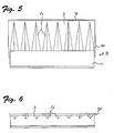
- FIGS. 5 and 6 show further sealing means 50 which are attached to the right vertical edge of the baffle 3, to effect the sealing of the butt joints between the baffles of adjacent locking elements in devices with a plurality or plurality of locking elements.
- the joint seal 50 extends from the upper edge of the wall 3 to below the sealing region 9 on the buoyancy body 4.
- the wall 3 projects laterally over the float, so that this supernatant engages behind the vertical sealing means of a blocking element on the left and the two Walls are sealed against each other.
- the vertical sealing means 50 extend down to a region between adjacent buoyancy bodies.
- the sealing means 50 thereby ensure that the sealing of the butt joints extends below the horizontal sealing area on the rear side of the blocking elements, thereby keeping the flood protection device tight in the area between adjacent blocking bodies.
- the vertical sealing means do not restrict the relative vertical mobility of the locking body to each other and are designed so that they do not catch or hinder each other when floating.
- the geometry of the shaft elements is designed such that narrow guides with small tolerances between locking body, in particular the buoyancy body and the shaft walls are avoided.
- FIG. 1 and the FIG. 2 such a system is shown in which the rear wall 52 of the shaft 5 is exempted up to an upper region 51 soiling such as stones or branches, which can penetrate into the shaft, especially when used in rivers, place in the spaces 56 space and obstruct the Mobility of the locking body 2 in the shaft 5 not.
- FIG. 1 In the FIG. 1 is indicated that can be accommodated in the shaft 5 or in a separate compartment 57 below the shaft 5 as additional benefits other installations such as cable ducts or other lines.
- the shaft is preferably made on site, for example, with a wall thickness of 14 cm made of reinforced concrete, cast steel fiber or polymer fiber concrete, or prefabricated finished parts of such materials are installed in corresponding trenches In both cases, civil engineering work is required, with little overhead as described above can be used.
- the devices are not sunk in the ground, but formed as parts of infrastructure in the bank area
- the device according to the present invention may serve as part of quay walls or as above-ground barrier walls, which in an emergency by means of extendable barrier body to increase the effective height of the dam wall.
Landscapes
- Engineering & Computer Science (AREA)
- General Engineering & Computer Science (AREA)
- Environmental & Geological Engineering (AREA)
- Ocean & Marine Engineering (AREA)
- Mechanical Engineering (AREA)
- Civil Engineering (AREA)
- Structural Engineering (AREA)
- Revetment (AREA)
- Barrages (AREA)
Abstract
Description
Die vorliegende Erfindung betrifft eine Hochwasserschutzvorrichtung gemäss Oberbegriff des unabhängigen Patentanspruchs 1.The present invention relates to a flood protection device according to the preamble of independent claim 1.
Aus der
Ein entscheidender Nachteil dieser Konstruktion besteht darin, dass die Kammer nach dem Einbau von aussen nicht mehr zugänglich ist. Der Schwimmkörper ist in der Kammer gefangen und kann weder zu Wartungsarbeiten noch zur Reinigung der Kammer entfernt werden. Sollten Schwemmmaterial oder Geschiebe, zum Beispiel Steinbrocken oder Äste, in die Kammer eingedrungen sein, so lassen sich diese nicht ohne bauliche Massnahmen entfernen. Angesichts der hohen Investitionskosten und der geringen Fehlertoleranz der sicherheitsrelevanten Einsatzgebiete muss davon ausgegangen werden, dass das System allein aufgrund dieses Mangels an Wartungsfreundlichkeit abgelehnt werden wird. Die potentiellen Kunden sind in erster Linie Kommunen oder andere öffentliche Organe, die es sich nicht leisten können, Millionenbeträge in eine Infrastruktur zu investieren, deren Funktionstüchtigkeit im Ernstfall nicht 100%-ig gewährleistet ist.A major disadvantage of this design is that the chamber is no longer accessible after installation from the outside. The float is trapped in the chamber and can not be removed for maintenance or cleaning of the chamber. If any debris or debris, such as rocks or branches, have penetrated the chamber, they can not be removed without structural measures. In view of the high investment costs and the low fault tolerance of the security-relevant applications, it must be assumed that the system will be rejected solely because of this lack of serviceability. The potential customers are first and foremost municipalities or other public bodies that can not afford to invest millions in an infrastructure whose functioning is not 100% guaranteed in an emergency.
Es ist in der
Der Wasserdruck, dem die Dichtmittel ausgesetzt sind, nimmt jedoch mit dem steigenden Wasserpegel zu und kann gerade bei Fliessgewässern noch erheblich durch den Staudruck erhöht werden. Hält die Dichtung dieser Belastung nicht stand, so kommt es zum Umspülen und die Vertikalwand bleibt im schlimmsten Fall völlig wirkungslos, da sie vom Hochwasser gar nicht wirksam erreicht wird.The water pressure to which the sealant is exposed, however, increases with the increasing water level and can be increased even in rivers significantly by the back pressure. If the seal does not withstand this load, flushing occurs and the vertical wall remains completely ineffective in the worst case, since it is not effectively reached by the flood.
Ein weiterer Nachteil der Vorrichtung gemäss der
Ein Nachteil von Systemen mit Wasserzuleitungen unterhalb der Dammkrone, wie sie zum Beispiel aus der
Es ist daher die Aufgabe der vorliegenden Erfindung, eine Hochwasserschutzvorrichtung zur Verfügung zu stellen, die die oben erwähnten Nachteile nicht aufweist. Es soll eine Vorrichtung zur Verfügung gestellt werden, die im Ernstfall ein Höchstmass an Hochwasserschutz bietet, indem sie auch bei Verschmutzung funktioniert und bei jedem Wasserdruck ausreichend dicht ist. Ausserdem sollen Herstellung, Montage und Wartung der Vorrichtung kostengünstig sein.It is therefore the object of the present invention to provide a flood protection device which does not have the above-mentioned disadvantages. It should be provided a device that provides the highest level of flood protection in case of emergency, by working well in case of pollution and is sufficiently dense at any water pressure. In addition, production, installation and maintenance of the device should be cost-effective.
Diese Aufgabe wird durch ein Gerät mit den Merkmalen des Anspruchs 1 erfüllt.This object is achieved by a device having the features of claim 1.
Weitere vorteilhafte Ausführungsformen des erfindungsgemässen Gerätes ergeben sich aus den abhängigen Ansprüchen.Further advantageous embodiments of the inventive device will become apparent from the dependent claims.
Die erfindungsgemässen Vorrichtungen stellen keine Beeinträchtigung des Ortsbildes respektive der Uferzonen dar, da sie im Boden oder in bestehenden Deichanlagen versenkbar oder derart an bestehenden Schutzverbauungen anbringbar sind, dass sie ein gestalterisch ästhetisches Element darstellen. Der Einbau der neuen Vorrichtung lässt sich vornehmen, ohne dass der Abflussquerschnitt bei Fliessgewässern verringert wird.The devices according to the invention do not impair the appearance of the village or the riparian zones, since they can be lowered in the ground or in existing dike installations or can be attached to existing protective structures in such a way that they represent an aesthetically pleasing element in design. The installation of the new device can be made without the flow cross section is reduced in rivers.
Die erfindungsgemässe Konstruktion, insbesondere die Reduktion auf ein Minimum an beweglichen Bauteilen, führt zu einem geringen Wartungsaufwand bei gleichzeitiger, hoher Zuverlässigkeit im Gebrauchsfall. Die erfindungsgemässe Konstruktion erlaubt es, zur Reinigung, respektive zur Wartung, auch direkte Umwelteinflüsse wie Regen zu nutzen.The construction according to the invention, in particular the reduction to a minimum of moving components, leads to a low maintenance expenditure at the same time, higher Reliability in use. The inventive construction makes it possible to use for cleaning, respectively for maintenance, even direct environmental influences such as rain.
Ein besonderer Vorteil der Erfindung liegt darin, dass sich die Sperrkörper mit geringem Aufwand aus den Schächten entfernen lassen. Wartungs- und/oder Kontrollarbeiten an den Sperrkörpern und/oder den Schächten, inklusive Zu- und Ableitungen, können dadurch kostengünstig vorgenommen werden. Im Falle von beschädigten oder verformten Sperrkörpern ermöglicht dies ein schnelles Entfernen zur Reparatur oder ein Austauschen.A particular advantage of the invention is that the locking body can be removed with little effort from the shafts. Maintenance and / or control work on the barrier bodies and / or the shafts, including inlets and outlets, can be made inexpensively. In the case of damaged or deformed barrier bodies, this allows for quick removal for repair or replacement.
Die neue Vorrichtung ist bei ebenerdigem Einbau LKW-überfahrbar, so dass an den teilweise befahrbaren Ufern bei Normalwasserstand der Verkehr nicht behindert ist Besonders vorteilhaft hat sich dabei erwiesen, dass die üblichen strassenbautechnischen Strassengefälle von maximal 1 bis 1.5% von der erfindungsgemässen Vorrichtung überwindbar sind.The new device is truck overrun at ground level installation, so that the partially navigable banks at normal water level, the traffic is not hindered It has proven particularly advantageous that the usual road-building road gradient of at most 1 to 1.5% of the inventive device can be overcome.
Die neuen Vorrichtungen lassen sich gemäss vorteilhafter manueller Ausführungsformen von nur wenigen oder sogar nur einer Person aktivieren und bedienen. In einer voll automatisierten Version wird zumindest das Ausfahren der Sperrkörper mit den Stauwänden von einer Steuerung mit entsprechenden Sensoren gesteuert. In jedem Fall führt die neue Vorrichtung dazu, dass nicht länger zahlreiche Helfer im Hochwasserfall vor Ort Dämme oder mobile Sperren errichten müssen. Die Unabhängigkeit von zahlreichen Helfern macht das neue System gerade auch für den Einsatz in schlecht zugänglichen oder dünn besiedelten Gebieten attraktiv.The new devices can be activated and operated according to advantageous manual embodiments of only a few or even only one person. In a fully automated version, at least the extension of the blocking bodies with the retaining walls is controlled by a controller with corresponding sensors. In any case, the new device means that no longer numerous helpers in the case of floods on site dams or mobile barriers must be established. The independence of numerous helpers makes the new system particularly attractive for use in poorly accessible or sparsely populated areas.
Zu Übungszwecken, zum Beispiel zu jährlichen Hochwassertests, lassen sich die neuen Vorrichtungen einfach und ohne grossen Aufwand testen.For training purposes, such as annual flood tests, the new devices can be tested easily and without much effort.
Die Herstellung der erfindungsgemässen Vorrichtungen ist bereits bei kleinen Stückzahlen an Sperrkörpern und Schächten äusserst kostengünstig, da sie fertigungstechnisch einfach, d.h. ohne besondere Gerätschaften oder Werkzeuge, durchführbar ist Bei grösseren Stückzahlen lässt sich die Herstellung rationalisieren, so dass die Anschaffungskosten auf ein für öffentliche oder auch private Bauträger interessantes Mass gesenkt werden können.The production of the devices according to the invention is extremely cost-effective even with small quantities of blocking bodies and shafts, since they are simple in terms of production engineering, ie, can be carried out without special equipment or tools For larger quantities, the production can be rationalized, so that the acquisition costs can be reduced to an interesting for public or private builders Mass.
Bei der neuen Hochwasserschutzvorrichtung für Uferbereiche eines Gewässers mit veränderlichem Wasserpegel ist mindestens ein Sperrkörper in einem oben offenen Schacht zumindest vertikalbeweglich untergebracht. Der Sperrkörper umfasst eine vertikale Stauwand, die auf einem Auftriebskörper angebracht ist. Je nach Ausführungsform und Einsatzsituation sind vorzugsweise mehrere Sperrkörper in einem Schacht untergebracht. Bei grösseren Anlagen können mehrere Schächte oder baulich voneinander getrennte Schachtabschnitte aneinander gereiht werden, so dass ein Hochwasserschutz über viele Meter oder sogar Kilometer möglich ist. Bei normalem Wasserstand sind die Sperrkörper vorzugsweise vollumfänglich in den Schächten versenkt. Jeder Schacht ist über mindestens einen Beflutungsdurchlass flutbar, wobei die Flutung der Schächte vorzugsweise aktiv erfolgt Das heisst, die Schächte werden nicht mit dem ansteigenden Wasser aus dem einzudämmenden Gewässer geflutet, sondern über Druckleitungen mit Leitungswasser oder Wasser, das aus einem geeigneten Reservoir gepumpt wird. Dadurch lässt sich die Anlage beliebig unabhängig vom Pegelstand des Gewässers steuern.In the new flood protection device for riparian areas of a water body with variable water level at least one locking body is housed in a top open shaft at least vertically movable. The lock body includes a vertical baffle mounted on a buoyant body. Depending on the embodiment and application situation, a plurality of blocking bodies are preferably accommodated in a shaft. In larger systems, several shafts or structurally separate shaft sections can be lined up, so that a flood protection over many meters or even kilometers is possible. At normal water level, the blocking bodies are preferably fully sunk in the shafts. Each shaft is floodable via at least one Beflutungsdurchlass, the flooding of the shafts is preferably active that is, the wells are flooded not with the rising water from the einzemmämmenden water, but via pressure lines with tap water or water, which is pumped from a suitable reservoir. This allows the system to be controlled independently of the level of the water body.
Es ist ein wesentliches Merkmal der vorliegenden Erfindung, dass die Schächte derart oben offen ausgebildet sind, dass die Sperrelemente herausgenommen werden können. In bevorzugten Ausführungsformen sind Anschlagmittel in oberen Bereichen der Schächte angeordnet, die die Vertikalbeweglichkeit der Sperrkörper begrenzen. Beim Fluten der Schächte werden die Sperrkörper von den Auftriebskörpern angehoben, bis sie in einer oberen ausgefahrenen Position an den Anschlagmitteln anliegen. Die Anschlagmittel sind lösbar an den oberen Bereichen der Schachtwand befestigt und lassen sich mit wenig Aufwand entfernen. Dadurch ist sichergestellt, dass die Sperrkörper, ohne bauliche Veränderungen am Schacht vornehmen zu müssen, aus den Schächten entfernt werden können. Vorzugsweise sind an einer Unterkante der Sperrkörper korrespondierende Anschlagmittel ausgebildet, die mit den Anschlagmitteln der Schachtwand zusammenwirken.It is an essential feature of the present invention that the shafts are formed open at the top so that the locking elements can be removed. In preferred embodiments, stop means are arranged in upper regions of the shafts which limit the vertical mobility of the blocking bodies. When flooding the shafts, the blocking bodies are lifted by the buoyancy bodies until they rest in an upper extended position on the stop means. The stop means are releasably attached to the upper regions of the shaft wall and can be removed with little effort. This ensures that the lock body, without having to make structural changes to the shaft, can be removed from the shafts. Preferably are on a bottom edge of the locking body corresponding stop means formed, which cooperate with the stop means of the shaft wall.
Eine entscheidende Rolle kommt auch den Dichtmitteln zu, die den Sperrkörper zumindest gegen eine Schachtwand abdichten, um ein Umspülen des Sperrkörpers zu verhindern. Vorzugsweise sind diese zumindest zwischen einem oberen Widerlager der rückseitigen Kammerwand und einer rückseitigen Dichtfläche des Sperrkörpers angeordnet. Unter Vorderseite, respektive vorne, soll in Zusammenhang mit der vorliegenden Erfindung die dem einzudämmenden Gewässer zugewandte Seite verstanden werden. Unter Rückseite oder hinten wird entsprechend, sofern nichts anderes ausdrücklich erwähnt ist, die dem einzudämmenden Gewässer abgewandte Seite verstanden.A crucial role is also the sealants that seal the locking body at least against a shaft wall to prevent flushing of the locking body. Preferably, these are arranged at least between an upper abutment of the rear-side chamber wall and a rear-side sealing surface of the blocking body. Under front, respectively front, should be understood in the context of the present invention, the water to be contained facing side. Unless otherwise stated, the reverse or rear side is understood to mean the side facing away from the water to be contained.
Gemäss einer bevorzugten Ausführungsform der Erfindung ist die Stauwand nicht mittig auf dem Auftriebskörper angeordnet, sondern ist an einem hinteren Bereich der Auftriebskörper platziert, so dass der Sperrkörper nicht vollständig ausbalanciert ist, sondern beim Fluten nach hinten kippt. In einer besonders bevorzugten Ausführungsform fluchtet die Rückseite der Stauwand mit der Rückseite des Auftriebskörper und beide Seitenflächen liegen in einer gemeinsamen Ebene. Im versenkten Zustand liegt ein oberer Bereich der Rückwand an einem oberen Bereich der Innenseite der hinteren Schachtwand an. In diesem Bereich verlaufen vorzugsweise die Dichtmittel in der Schachtwand. Diese umfassen vorzugsweise Gummipressdichtungen und sind reibungsarm konstruiert, um die Aufwärtsbewegung des Sperrkörpers nicht zu sehr abzubremsen. Da der Schwerpunkt des Sperrkörpers aus der Mitte nach hinten gerückt ist, liegt der Schwimmkörper in der Ruheposition während dem Aufschwimmen und in der ausgefahrenen Position kontinuierlich an der hinteren Schachtwand an. Dadurch ist sichergestellt, dass kein Fremdmaterial eindringen und den Dichtschluss beeinträchtigen kann. Mit Ansteigen des Hochwassers nimmt der Wasserdruck gegen die Innenseite der Sperrwand zu, wobei die Stauwand als Hebel wirkt, der die Rückwand des Sperrelements gegen die ununterbrochen längsverlaufenden Dichtmittel drückt. Auch bei dynamischen Wasserbewegungen, zum Beispiel bei Wellenschlag, ist durch die erfindungsgemässe Konstruktion stets eine ausreichende Dichtwirkung gewährleistet Zusätzlich oder alternativ lassen sich an der Rückwand des Sperrkörpers in einem unteren Bereich, der im ausgefahrenen Zustand gegen die Schachtwand drückt, Dichtmittel, anbringen.According to a preferred embodiment of the invention, the stowage wall is not arranged centrally on the buoyant body, but is placed at a rear area of the buoyancy bodies, so that the blocking body is not completely balanced, but tilts backwards when flooded. In a particularly preferred embodiment, the rear side of the stowage wall is aligned with the rear side of the buoyant body and both side surfaces lie in a common plane. In the retracted state, an upper portion of the rear wall abuts an upper portion of the inner side of the rear shaft wall. In this area, preferably the sealing means extend in the shaft wall. These preferably include rubber press seals and are designed with low friction to not slow down the upward movement of the locking body too much. Since the center of gravity of the locking body is moved from the center to the rear, the float is in the rest position during the floating and in the extended position continuously to the rear shaft wall on. This ensures that no foreign material can penetrate and impair the sealing. As the flood increases, the water pressure against the inside of the barrier wall increases, with the baffle wall acting as a lever urging the rear wall of the barrier member against the continuous longitudinal sealing means. Also at dynamic water movements, for example, when waves, is always ensured by the inventive construction a sufficient sealing effect Additionally or alternatively can be on the rear wall of the locking body in a lower region, which presses in the extended state against the shaft wall sealant attach.
Bei Anlagen mit einer Mehrzahl oder Vielzahl von Sperrelementen ist zusätzlich die Abdichtung zwischen den Stauwänden benachbarter Sperrelemente und zwischen benachbarten Auftriebskörpern und der Schachtwand sichergestellt. Zur Abdichtung der Stossfugen benachbarter Sperrkörper gegeneinander werden die Sperrkörper vorzugsweise mit abgedichtetem Hintergriff ausgestaltet, wobei die relative Vertikalbeweglichkeit der Sperrkörper zueinander nicht eingeschränkt istIn systems with a plurality or plurality of blocking elements, the sealing between the retaining walls of adjacent blocking elements and between adjacent buoyancy bodies and the shaft wall is additionally ensured. For sealing the butt joints of adjacent blocking bodies against each other, the blocking bodies are preferably designed with a sealed rear grip, wherein the relative vertical mobility of the blocking bodies is not restricted to one another
Da die Bemessung des Volumens des Auftriebskörpers und die damit erreichbare Auftriebskraft begrenzt ist, insbesondere die Sperrelemente aber hohen, statischen und dynamischen Belastungen standhalten müssen, müssen sie hinsichtlich Gewicht, Materialwahl und Stabilität optimiert werden. Die Sperrelemente sind hinsichtlich der zu übernehmenden Funktionen Auftrieb und Hochwassersperre zweigeteilt. Dies spiegelt sich in der Unterteilung in Auftriebskörper und Stauwand wieder. Da die Stauwand nichts zum Auftrieb beitragen muss, ist sie auf hohe Stabilität bei geringst möglichem Gewicht optimiert Der Auftriebskörper muss die in die Stauwand eingeleiteten Kräfte aufnehmen können und ist entsprechend auf hohe Stabilität, hohe Wasserverdrängung bei kleinem Gewicht, maximiert. Konstruktionen aus Aluminium und oder faserverstärkten Kunststoffen haben sich in Tests als vorteilhaft erwiesen. Die grossen Hohlkörper der Auftriebskörper werden dabei jeweils vorzugsweise ausgeschäumt, um die Stabilität zu erhöhen. Das Volumen des Auftriebskörper ist primär durch die Herstellungskosten und die Kosten für die Erstellung des Schachtes beschränkt, der so tief sein muss, dass er den Auftriebskörper mitsamt der Stauwand aufnehmen kann. Als Zusatznutzen können im Schacht weitere Installationen wie Kabelschächte oder Leitungen vorgesehen oder verlegt sein.Since the design of the volume of the buoyant body and the buoyancy force achievable therewith is limited, in particular the barrier elements have to withstand high, static and dynamic loads, they have to be optimized in terms of weight, choice of material and stability. The blocking elements are divided into two parts with regard to the functions to be taken over buoyancy and flood barrier. This is reflected in the subdivision into buoyancy body and retaining wall. Since the baffle wall does not have to contribute to the buoyancy, it is optimized for high stability at the lowest possible weight The buoyant body must be able to absorb the forces introduced into the bulkhead and is accordingly maximized for high stability, high water displacement at low weight. Structures made of aluminum and / or fiber-reinforced plastics have proven to be advantageous in tests. The large hollow bodies of the buoyancy bodies are preferably each foamed in order to increase the stability. The volume of the buoyant body is primarily limited by the manufacturing costs and the cost of constructing the well, which must be so deep that it can accommodate the buoyant body together with the bulkhead. As additional benefits, further installations such as cable ducts or pipes can be provided or laid in the shaft.
Um die Überfahrbarkeit der Vorrichtung zu gewährleisten, ohne das Gewicht des Sperrkörpers, insbesondere der Stauwand, zu erhöhen, ist eine separate Abdeckung vorgesehen, die den Schacht stabil und vorzugsweise schmutzdicht verschliesst. Die Abdeckungen sind gemäss einer bevorzugten Ausführungsform so ausgebildet, dass sie vom Sperrelement beim Aufschwimmen selbsttätig geöffnet werden und den Schacht vollständig freigeben. In weiteren Ausführungsformen lassen sie sich von Hand oder einem entsprechenden Antrieb öffnen oder entfernen. In besonders bevorzugten Ausführungsformen ist die Abdeckung als Deckel ausgebildet, der mit Scharniermitteln an der Oberkante einer Schachtwand schwenkbeweglich angeordnet istIn order to ensure the Überfahrbarkeit the device without increasing the weight of the locking body, in particular the baffle, a separate cover is provided, which closes the shaft stable and preferably dirt-tight. The covers are according to a preferred embodiment designed so that they are automatically opened by the blocking element when floating and completely release the shaft. In other embodiments, they can be opened or removed by hand or a corresponding drive. In particularly preferred embodiments, the cover is formed as a lid, which is pivotally mounted with hinge means on the upper edge of a shaft wall
Die Geometrie der Schachtelemente ist derart ausgelegt, dass enge Führungen mit kleinen Toleranzen zwischen Sperrkörper, insbesondere dem Auftriebskörper und den Schachtwänden, vermieden werden. Dies gewährleistet ein robustes System und verhindert, dass bereits kleinere Verschmutzungen wie Steine oder Äste die Beweglichkeit der Sperrkörper im Schacht beeinträchtigen oder blockieren können. Kommt es beim Fluten der Schächte dennoch zum Blockieren einzelner Sperrkörper in nicht vollständig ausgefahrenen Positionen, so lassen sich die Blockierungen meist durch einfaches Rütteln oder Hin- und Herbewegen der Sperrkörper von Hand lösen.The geometry of the shaft elements is designed so that narrow guides with small tolerances between locking body, in particular the buoyancy body and the shaft walls are avoided. This ensures a sturdy system and prevents even minor soiling such as stones or branches can affect or block the mobility of the locking body in the shaft. If, however, flooding of the shafts still leads to the blocking of individual blocking bodies in positions which are not completely extended, the blockings can usually be released by simple shaking or reciprocating movement of the blocking bodies by hand.
Die Schächte der erfindungsgemässen Vorrichtungen weisen neben den bereits beschriebenen Zuläufen auch Auslasskanäle im Bodenbereich auf, so dass sie nach dem Fluten entleerbar sind. Der Boden der Schächte ist dabei derart zu den Auslässen hin geneigt, dass beim Entleeren kein Wasser im Schacht zurück bleibt. Die Auslasskanäle sind vorzugsweise zum Gewässer hin gerichtet und jeweils mit Sperr- oder vorzugsweise Rückflusssperrventilen gegen ein unkontrolliertes Eindringen von Wasser gesichert.The shafts of the inventive devices have in addition to the already described inlets and outlet channels in the bottom area, so that they can be emptied after flooding. The bottom of the shafts is inclined to the outlets so that when emptying no water in the shaft remains. The outlet channels are preferably directed towards the water and each secured with barrier or preferably non-return valves against uncontrolled ingress of water.
Im Folgenden wird die vorliegende Erfindung unter Bezugnahme auf eine in den Figuren gezeigte, bevorzugte Ausführungsform der erfindungsgemässen Vorrichtung genauer erläutert. Es zeigen :
- Fig. 1
- eine Seitenansicht einer Hochwasserschutzvorrichtung gemäss einer bevorzugten Ausführungsform der Erfindung mit einem Sperrelement in einer oberen ausgefahrenen Position;
- Fig. 2
- die Ansicht gemäss
Fig. 1 mit dem Sperrelement in einer unteren Ruheposition, wobei ein zusätzlicher unterer Schachtbereich nicht dargestellt ist; - Fig. 3
- ein Sperrelement gemäss der Ausführungsform der
Figuren 1 und 2 in perspektivischer Ansicht von schräg vorne, wobei die Dichtmittel zum Abdichten gegenüber benachbarten Sperrelementen weggelassen sind; - Fig. 4
- das
Sperrelement gemäss Figur 3 in Seitenansicht; - Fig. 5
- das
Sperrelement gemäss Figuren 3 und 4 in einer Ansicht von vorne, wobei die Dichtmittel zum Abdichten gegenüber einem Sperrelement dargestellt sind; und - Fig. 6
- das Sperrelement gemäss
Figur 5 in einer Sicht von oben.
- Fig. 1
- a side view of a flood protection device according to a preferred embodiment of the invention with a locking element in an upper extended position;
- Fig. 2
- the view according to
Fig. 1 with the locking element in a lower rest position, wherein an additional lower shaft area is not shown; - Fig. 3
- a blocking element according to the embodiment of
Figures 1 and 2 in a perspective view obliquely from the front, wherein the sealing means for sealing against adjacent blocking elements are omitted; - Fig. 4
- the blocking element according to
FIG. 3 in side view; - Fig. 5
- the blocking element according to
FIGS. 3 and 4 in a front view, wherein the sealing means are shown for sealing against a locking element; and - Fig. 6
- the blocking element according to
FIG. 5 in a view from above.
In der
Da die Sperrelemente bereits durch die asymmetrische Gewichtsverteilung gegen die Dichtflächen gedrückt werden und das Hochwasser die Dichtwirkung verstärkt, ist auch bei dynamischen Wasserbewegungen, zum Beispiel bei Wellenschlag, eine ausreichende Dichtwirkung gewährleistetSince the blocking elements are already pressed by the asymmetric weight distribution against the sealing surfaces and the flood increases the sealing effect, a sufficient sealing effect is ensured even with dynamic water movements, for example, when waves
Der Schacht 5 ist im Wesentlichen U-förmig oben offen ausgebildet, wobei die oberseitige Öffnung so dimensioniert ist, dass die Sperrelemente 2 aus dem Schacht 5 herausgenommen werden können. Anschlagmittel 10 sind in oberen Bereichen einer vorderen Schachtwand 53 angeordnet, um die Vertikalbeweglichkeit der Sperrkörper 2 zu begrenzen. Beim Fluten der Schächte 5 werden die Sperrkörper 2 von den Auftriebskörpern 4 angehoben, bis sie in einer oberen ausgefahrenen Position mit einer Anschlagrippe 41 an den Anschlagmitteln 10 anliegen. Im dargestellten Ausführungsbeispiel sind die Anschlagmittel 10 lösbar an den oberen Bereichen der Schachtwand 53 befestigt, vorzugsweise verschraubt, und lassen sich mit wenig Aufwand entfernen. Zur Wartung, Reinigung oder Reparatur genügt es, die Anschläge abzuschrauben und schon lassen sich die Sperrkörper aus dem Schacht herausheben.The shaft 5 is substantially U-shaped open at the top, wherein the top-side opening is dimensioned so that the locking elements 2 can be removed from the shaft 5. Stop means 10 are arranged in upper regions of a
Für die Funktion der Anschlagmittel genügt es, zwei oder einige wenige Anschläge für jedes Sperrelement an der Schachtwand anzubringen. In einer weiteren bevorzugten Ausführungsform erstrecken sich die Anschläge 10 über die gesamte Länge des Schachtes 5 und wirken mit den ebenfalls ununterbrochen an der unteren Vorderkante des Auftriebselementes angeordneten Rippe 41 dichtend zusammen. Dichtmittel sind vorzugsweise an den längsverlaufenden Anschlägen angebracht Dichtmittel an den Längsrippen 41 der Sperrelemente würden beim Aufschwimmen an der vorderen Innenwand des Schachtes 5 reiben und könnten beschädigt werden oder das Hochfahren abbremsen.For the function of the stop means it is sufficient to attach two or a few stops for each locking element on the shaft wall. In a further preferred embodiment, the
Aus der
Im versenkten Zustand liegt ein oberer Bereich der Rückwand 3 an einem oberen Bereich 51 der Innenseite der hinteren Schachtwand an. Der Schacht ist tief genug, dass der Sperrkörper 2 vollständig aufgenommen, respektive versenkt, werden kann und sich der Deckel 11 problemlos schliessen lässt Zum Fluten lässt sich Wasser über eine Zuleitung 6 über nicht weiter dargestellte Rohrleitungen in den Schachtinnenraum 55 pumpen und zum Ablassen oder Abpumpen des Wassers ist mindestens ein Auslasskanal 12 im Bodenbereich des Schachtes angebracht. Der Schachtboden 54 weist ein Gefälle zu den Auslässen hin auf, so dass beim Entleeren kein Wasser im Schacht zurückbleibt. Der Auslasskanal ist zur Gewässerseite hin gerichtet, während der Einlass auf der Gewässer-abgewandten Seite der Vorrichtung 1 angeordnet ist.In the retracted state, an upper portion of the
Auf die entscheidende Rolle, die den Dichtmitteln zukommt, ist oben bereits allgemein eingegangen worden. Aus den
In der
Aus der Seitenansicht der
Die Ansichten der
Grundsätzlich ist die Geometrie der Schachtelemente derart ausgelegt, dass enge Führungen mit kleinen Toleranzen zwischen Sperrkörper, insbesondere dem Auftriebskörper und den Schachtwänden vermieden werden. In der
In der
In weiteren, nicht in den Figuren dargestellten Ausführungsformen werden die Vorrichtungen nicht im Boden versenkt, sondern als Teile von lnfrastruktureinrichtungen im Uferbereich ausgebildet Die Vorrichtung gemäss der vorliegenden Erfindung kann als Teil von Kaimauern oder als oberirdische Sperrmauern dienen, der sich im Notfall mittels der ausfahrbaren Sperrkörper um die wirksame Höhe der Stauwand erhöhen lässt.In other embodiments, not shown in the figures, the devices are not sunk in the ground, but formed as parts of infrastructure in the bank area The device according to the present invention may serve as part of quay walls or as above-ground barrier walls, which in an emergency by means of extendable barrier body to increase the effective height of the dam wall.
- 11
- HochwasserschutzvorrichtungFlood protection device
- 22
- Sperrkörperblocking body
- 33
- Stauwandretaining wall
- 44
- Auftriebskörperbuoyancy
- 55
- Schachtshaft
- 66
- Zuleitungsupply
- 77
- Horizontale DichtmittelHorizontal sealant
- 99
- Dichtflächesealing surface
- 1010
- Anschlagattack
- 1111
- Deckelcover
- 1212
- Auslasskanalexhaust port
- 1313
- Verstärkungsrippenreinforcing ribs
- 3030
- Rückwandrear wall
- 3131
- Oberkante der StauwandTop edge of the stowage wall
- 4141
- Anschlagrippestop rib
- 4242
- Oberseite des AuftriebskörpersTop of the float
- 4343
- Vorderwand des AuftriebskörpersFront wall of the buoyancy body
- 5050
- Vertikale DichtmittelVertical sealant
- 5151
- Hintere SchachtwandRear shaft wall
- 5252
- Unterer Bereich der hinteren SchachtwandLower area of the rear shaft wall
- 5353
- Vordere SchachtwandFront shaft wall
- 5454
- Schachtbodenshaft bottom
- 5555
- SchachtinnenraumTray core
- 5656
- Freiraumfree space
- 5757
- Kompartimentcompartment
- F)F)
- Fahrbahnroadway
- G)G)
- Gewässerwaters
- P)P)
- Pegellevel
Claims (10)
Applications Claiming Priority (1)
| Application Number | Priority Date | Filing Date | Title |
|---|---|---|---|
| CH1072007 | 2007-01-24 |
Publications (2)
| Publication Number | Publication Date |
|---|---|
| EP1950352A2 true EP1950352A2 (en) | 2008-07-30 |
| EP1950352A3 EP1950352A3 (en) | 2013-07-03 |
Family
ID=39367699
Family Applications (1)
| Application Number | Title | Priority Date | Filing Date |
|---|---|---|---|
| EP08000903.8A Withdrawn EP1950352A3 (en) | 2007-01-24 | 2008-01-18 | Flood protection system |
Country Status (1)
| Country | Link |
|---|---|
| EP (1) | EP1950352A3 (en) |
Cited By (6)
| Publication number | Priority date | Publication date | Assignee | Title |
|---|---|---|---|---|
| NL1035546C2 (en) * | 2008-05-13 | 2009-11-16 | Den Noort Innovations B V Van | Self-closing flood barrier and method for protecting a hinterland using the same. |
| ITPC20100015A1 (en) * | 2010-06-11 | 2011-12-12 | Sverzellati Antonio Riccardo | HYDRAULIC MOBILE BARRIERS |
| WO2012084783A1 (en) | 2010-12-20 | 2012-06-28 | Floodprotect Limited | Dam body for a damming device and production method |
| WO2013189895A1 (en) | 2012-06-18 | 2013-12-27 | Floodprotect Limited | Dam device and method for producing a dam device |
| GB2524874A (en) * | 2014-02-13 | 2015-10-07 | Bluewater Design Associates Ltd | Self-activating flood protection barrier |
| CN107313498A (en) * | 2017-08-17 | 2017-11-03 | 北京北排装备产业有限公司 | A kind of intelligent well head flood control cylinder and its application method |
Citations (2)
| Publication number | Priority date | Publication date | Assignee | Title |
|---|---|---|---|---|
| EP0726364A1 (en) | 1995-02-09 | 1996-08-14 | Van den Noort, Johann Heinrich Reindert | Movable dam |
| WO2000001892A1 (en) | 1998-07-03 | 2000-01-13 | Fiona Meikle | Flood prevention barrier apparatus |
Family Cites Families (1)
| Publication number | Priority date | Publication date | Assignee | Title |
|---|---|---|---|---|
| DE10201882A1 (en) * | 2002-01-18 | 2003-07-31 | Roland Wegener | Automatically lifting flood barrier for bank of river is mounted on floats in chambers in bank filled from water inlets near top of bank |
-
2008
- 2008-01-18 EP EP08000903.8A patent/EP1950352A3/en not_active Withdrawn
Patent Citations (2)
| Publication number | Priority date | Publication date | Assignee | Title |
|---|---|---|---|---|
| EP0726364A1 (en) | 1995-02-09 | 1996-08-14 | Van den Noort, Johann Heinrich Reindert | Movable dam |
| WO2000001892A1 (en) | 1998-07-03 | 2000-01-13 | Fiona Meikle | Flood prevention barrier apparatus |
Cited By (10)
| Publication number | Priority date | Publication date | Assignee | Title |
|---|---|---|---|---|
| NL1035546C2 (en) * | 2008-05-13 | 2009-11-16 | Den Noort Innovations B V Van | Self-closing flood barrier and method for protecting a hinterland using the same. |
| ITPC20100015A1 (en) * | 2010-06-11 | 2011-12-12 | Sverzellati Antonio Riccardo | HYDRAULIC MOBILE BARRIERS |
| WO2012084783A1 (en) | 2010-12-20 | 2012-06-28 | Floodprotect Limited | Dam body for a damming device and production method |
| WO2013189895A1 (en) | 2012-06-18 | 2013-12-27 | Floodprotect Limited | Dam device and method for producing a dam device |
| GB2524874A (en) * | 2014-02-13 | 2015-10-07 | Bluewater Design Associates Ltd | Self-activating flood protection barrier |
| CN105980633A (en) * | 2014-02-13 | 2016-09-28 | 蓝水设计联合有限公司 | Self-activating flood protection barrier |
| GB2524874B (en) * | 2014-02-13 | 2017-03-08 | Bluewater Design Ass Ltd | Self-activating flood protection barrier |
| US9689129B2 (en) | 2014-02-13 | 2017-06-27 | Bluewater Design Associates Limited | Self-activating flood protection barrier |
| CN105980633B (en) * | 2014-02-13 | 2018-12-07 | 卓纳吉设计有限公司 | Self-excitation live-in flood defence barrier |
| CN107313498A (en) * | 2017-08-17 | 2017-11-03 | 北京北排装备产业有限公司 | A kind of intelligent well head flood control cylinder and its application method |
Also Published As
| Publication number | Publication date |
|---|---|
| EP1950352A3 (en) | 2013-07-03 |
Similar Documents
| Publication | Publication Date | Title |
|---|---|---|
| EP1950352A2 (en) | Flood protection system | |
| DE102008009519B3 (en) | Water barrier, in particular flood protection wall | |
| WO2016110438A1 (en) | Flood protection system | |
| EP1731682B1 (en) | Cascade sewer system for surface water | |
| DE202018102880U1 (en) | Bulkhead for flood control and passage with such a bulkhead | |
| DE4010221C2 (en) | ||
| DE102004033962B4 (en) | Retractable flood protection system | |
| DE10348024A1 (en) | Rigole arrangement with trench and shaft | |
| DE102017130818B3 (en) | Water barrier with a trough-shaped founding body | |
| DE10201882A1 (en) | Automatically lifting flood barrier for bank of river is mounted on floats in chambers in bank filled from water inlets near top of bank | |
| DE19942514A1 (en) | Flood barrier for rivers consist of ditch parallel to river bank, containing height-adjustable buoyancy tanks connected to water | |
| DE19646271C2 (en) | Flood protection wall | |
| DE102004015322B4 (en) | Flood barrier | |
| DE10023750C1 (en) | Device, to prevent water exit from channel opening at high water, has metal or hard plastics support frame fitted over channel opening and container sealed against ground around channel opening | |
| DE20308083U1 (en) | Flood protection system | |
| DE202006011308U1 (en) | Flood protective wall has bulkhead inserted in around or in dyke, on which head plate is fitted | |
| DE202009005371U1 (en) | Water dam for protection against floods | |
| KR102677744B1 (en) | movable weir that makes it easy to open and close the sedimentation prevention plate | |
| DE4301137C1 (en) | Weir dam | |
| AT508757B1 (en) | HYDRAULIC HIGH WATER PROTECTION WALL | |
| DE102006009401A1 (en) | Storage body for fluids e.g. rain water, has fluid storage derived partly on horizontal fluid level with storage body, and inclined to wavy surface of storage body is provided with sealing | |
| DE10239036A1 (en) | Self-supporting and frameless device used as protection against floodwater comprises a modular system consisting of self-supporting rigid containers filled with liquid | |
| DE880119C (en) | Locking device for locks, harbors, docks or waterways | |
| DE102014008895A1 (en) | Hydrodynamic weir to prevent erosion in rivers and maintain navigability at low tide | |
| DE2157652A1 (en) | APPLICABLE FLOOR DRAIN IN A BRICK-IN HOUSING |
Legal Events
| Date | Code | Title | Description |
|---|---|---|---|
| PUAI | Public reference made under article 153(3) epc to a published international application that has entered the european phase |
Free format text: ORIGINAL CODE: 0009012 |
|
| AK | Designated contracting states |
Kind code of ref document: A2 Designated state(s): AT BE BG CH CY CZ DE DK EE ES FI FR GB GR HR HU IE IS IT LI LT LU LV MC MT NL NO PL PT RO SE SI SK TR |
|
| AX | Request for extension of the european patent |
Extension state: AL BA MK RS |
|
| PUAL | Search report despatched |
Free format text: ORIGINAL CODE: 0009013 |
|
| AK | Designated contracting states |
Kind code of ref document: A3 Designated state(s): AT BE BG CH CY CZ DE DK EE ES FI FR GB GR HR HU IE IS IT LI LT LU LV MC MT NL NO PL PT RO SE SI SK TR |
|
| AX | Request for extension of the european patent |
Extension state: AL BA MK RS |
|
| RIC1 | Information provided on ipc code assigned before grant |
Ipc: E02B 3/10 20060101AFI20130527BHEP |
|
| 17P | Request for examination filed |
Effective date: 20131224 |
|
| RBV | Designated contracting states (corrected) |
Designated state(s): AT BE BG CH CY CZ DE DK EE ES FI FR GB GR HR HU IE IS IT LI LT LU LV MC MT NL NO PL PT RO SE SI SK TR |
|
| AKX | Designation fees paid |
Designated state(s): AT BE BG CH CY CZ DE DK EE ES FI FR GB GR HR HU IE IS IT LI LT LU LV MC MT NL NO PL PT RO SE SI SK TR |
|
| RAP1 | Party data changed (applicant data changed or rights of an application transferred) |
Owner name: NIEDERDORFER, NIRMALA |
|
| STAA | Information on the status of an ep patent application or granted ep patent |
Free format text: STATUS: THE APPLICATION IS DEEMED TO BE WITHDRAWN |
|
| 18D | Application deemed to be withdrawn |
Effective date: 20150801 |