EP1947052A2 - Arrangement at telescopic lifting beams - Google Patents
Arrangement at telescopic lifting beams Download PDFInfo
- Publication number
- EP1947052A2 EP1947052A2 EP08445001A EP08445001A EP1947052A2 EP 1947052 A2 EP1947052 A2 EP 1947052A2 EP 08445001 A EP08445001 A EP 08445001A EP 08445001 A EP08445001 A EP 08445001A EP 1947052 A2 EP1947052 A2 EP 1947052A2
- Authority
- EP
- European Patent Office
- Prior art keywords
- lifting
- casing
- beams
- pressure spring
- support
- Prior art date
- Legal status (The legal status is an assumption and is not a legal conclusion. Google has not performed a legal analysis and makes no representation as to the accuracy of the status listed.)
- Withdrawn
Links
- 238000005452 bending Methods 0.000 description 3
- 238000006073 displacement reaction Methods 0.000 description 2
- 230000000284 resting effect Effects 0.000 description 2
Images
Classifications
-
- B—PERFORMING OPERATIONS; TRANSPORTING
- B66—HOISTING; LIFTING; HAULING
- B66F—HOISTING, LIFTING, HAULING OR PUSHING, NOT OTHERWISE PROVIDED FOR, e.g. DEVICES WHICH APPLY A LIFTING OR PUSHING FORCE DIRECTLY TO THE SURFACE OF A LOAD
- B66F3/00—Devices, e.g. jacks, adapted for uninterrupted lifting of loads
- B66F3/24—Devices, e.g. jacks, adapted for uninterrupted lifting of loads fluid-pressure operated
- B66F3/25—Constructional features
- B66F3/26—Adaptations or arrangements of pistons
- B66F3/28—Adaptations or arrangements of pistons telescopic
-
- A—HUMAN NECESSITIES
- A61—MEDICAL OR VETERINARY SCIENCE; HYGIENE
- A61G—TRANSPORT, PERSONAL CONVEYANCES, OR ACCOMMODATION SPECIALLY ADAPTED FOR PATIENTS OR DISABLED PERSONS; OPERATING TABLES OR CHAIRS; CHAIRS FOR DENTISTRY; FUNERAL DEVICES
- A61G7/00—Beds specially adapted for nursing; Devices for lifting patients or disabled persons
- A61G7/10—Devices for lifting patients or disabled persons, e.g. special adaptations of hoists thereto
-
- F—MECHANICAL ENGINEERING; LIGHTING; HEATING; WEAPONS; BLASTING
- F16—ENGINEERING ELEMENTS AND UNITS; GENERAL MEASURES FOR PRODUCING AND MAINTAINING EFFECTIVE FUNCTIONING OF MACHINES OR INSTALLATIONS; THERMAL INSULATION IN GENERAL
- F16B—DEVICES FOR FASTENING OR SECURING CONSTRUCTIONAL ELEMENTS OR MACHINE PARTS TOGETHER, e.g. NAILS, BOLTS, CIRCLIPS, CLAMPS, CLIPS OR WEDGES; JOINTS OR JOINTING
- F16B7/00—Connections of rods or tubes, e.g. of non-circular section, mutually, including resilient connections
- F16B7/10—Telescoping systems
Definitions
- This invention relates to an arrangement at at least two telescopically protrudable lifting beams, of which one is connected to a driving means in order to displace the second beam to-and-fro in said first beam, whereby a casing can be brought to surround both beams resting on them and extending a long part of the beams.
- Lifting beams of this type are used, e.g. within the medical service for lifting means, when a person is being lifted from a sitting position to a standing position or from one place to another. Telescopic lifting beams of this kind are also used for other lifting purposes for patients.
- the lifting beams are normally loaded in their longitudinal direction and they are designed to meet such a load.
- the lifting beams can be driven hydraulically via gears or manually using rope-driving means or with the help of a crank means.
- the object of the invention is to increase the strength of the lifting beams when they are in their protruded position and that this is accomplished by simple means, which are cheap.
- SE 516855 discloses such a solution consisting of a casing, which can be displaced on the beams so it covers e.g. half of the fixed beam and the first half of the protrudable beam so that the casing also takes up the bending stresses.
- the object of the invention is to simplify the design of the means, which perform the displacement of the casing when the movable beam is protruded for carrying out its lifting movement.
- the characteristics of the invention are stated in the following claim 1.
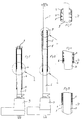
- Fig. 1 is hereby a partly longitudinal cross section of the lifting arrangement, having both lifting arms in retracted position.
- Fig. 2 is a partly longitudinal cross section as in fig. 1 , but the movable lifting arms are in protruded position.
- Fig. 3 is an enlarged cross section at the position a in fig. 1 .
- Fig. 4 is an enlarged part of the cross section at position B in fig. 2 .
- Fig. 5 is a part of an enlarged cross section at position C in fig. 2 .
- the arrangement shown in fig. 1 and 2 comprises a lifting beam 1, which is telescoping in a second lifting beam 2, being fixed to a driving means 3 which displaces the first lifting beam 1.
- the driving means 3 can be any known engine as e.g. an hydraulic engine or a gear motor, which drives the lifting beam 1 telescoping in the lifting beam 2.
- the lifting beams are loaded when the lifting beam 1 is protruding out of the lifting beam 2 in the position shown in fig. 2 .
- the lifting beams 1 and 2 are surrounded by a telescopic pipe or casing 4, which is displaceable over the two lifting beams 1 and 2.
- FIG. 1 shows the position of the lifting beams in which the telescopic casing 4 is completely displaced downwards over the fixed lifting beam 2.
- Fig. 2 shows the telescopic casing 4 being placed over the half length of the lifting beam 1 and over the half length of the lifting beam 2.
- the displacement of the telescopic casing 4 from the position shown in fig. 1 to the position shown in fig. 2 is performed by a pressure spring 5 which is located within the lifting beam 2.
- the telescopic casing 4 can also be said to be a case or casing.
- the end of the pressure spring 5 which faces the driving means 3 rests on a support 6 which is attached about on the middle of the lifting arm 2.
- the second end of the pressure spring 3 is supported by a cover 7 on the upper end of the telescoping casing 4.
- the power of the pressure spring 5 can be so adapted that the casing 4 will cover as much of the lifting beam 1 as of the lifting beam 2 when the lifting beam 1 is in its most protruded position.
- the casing 4 in its lower end that is to say the end which is closest to the lifting means, is a ring 8 which will rest against the support 6 when the casing 4 is in the position shown in fig. 2 by being displaced by the pressure spring 5.
- the length of the casing 4 shall advisably be half of the lifting beam 1 plus half of the lifting beam 2 as shown in fig. 2 .
- the ring 8 also acts as a support between the casing 4 and the lifting arm 2, and the cover 7 on the casing 4 is designed to act in the same way in relation to the lifting beam 1.
- the casing 4 will take up bending forces on the lifting beams specifically within the area where the lifting beam 2 is telescopically protruded out of the lifting beam 2.
- Fig. 3 shows a part of a longitudinal cross section at the area A in fig. 1 .
- This figure shows the support 6 which is attached to the casing against which the lower end of the pressure spring is resting.
- Fig. 4 shows a longitudinal cross section of the lower part of the casing in the position B in fig. 2 .
- the casing has been displaced by the pressure spring 5 so far as possible by that the pressure spring 5 has carried out a pressure between the support 6 and the cover 7 of the casing 4.
- the support ring 8 is shown, which forms a support between the lifting beam 2 and the casing 4.
- the ring may also form a limitation for how far the casing 4 can be displaced upwards on the lifting beam 2 by that the support 6 will come to rest on the ring 8. The support 6 is thus firmly attached to the inner side of the casing 4.
- Fig. 5 shows a longitudinal cross section of the upper part of the casing 4 at a position C in fig. 2 . It is hereby seen that the pressure spring 5 rests on the cover 7 attached at the upper end of the casing 4.
- the support ring may be omitted by that the outer dimension of the lifting arm 2 is adapted to the inner dimension of the casing in an area below the pressure spring 5, that is to say in the area B according to fig. 2 .
- the upper end of the casing can be designed in another way and have a design similar to a ring instead of a cover.
Landscapes
- Engineering & Computer Science (AREA)
- Mechanical Engineering (AREA)
- Life Sciences & Earth Sciences (AREA)
- General Engineering & Computer Science (AREA)
- Health & Medical Sciences (AREA)
- Structural Engineering (AREA)
- Geology (AREA)
- Public Health (AREA)
- General Health & Medical Sciences (AREA)
- Veterinary Medicine (AREA)
- Animal Behavior & Ethology (AREA)
- Nursing (AREA)
- Accommodation For Nursing Or Treatment Tables (AREA)
- Conveying And Assembling Of Building Elements In Situ (AREA)
- Forklifts And Lifting Vehicles (AREA)
- Jib Cranes (AREA)
Abstract
Description
- This invention relates to an arrangement at at least two telescopically protrudable lifting beams, of which one is connected to a driving means in order to displace the second beam to-and-fro in said first beam, whereby a casing can be brought to surround both beams resting on them and extending a long part of the beams.
- Lifting beams of this type are used, e.g. within the medical service for lifting means, when a person is being lifted from a sitting position to a standing position or from one place to another. Telescopic lifting beams of this kind are also used for other lifting purposes for patients.
- The lifting beams are normally loaded in their longitudinal direction and they are designed to meet such a load. The lifting beams can be driven hydraulically via gears or manually using rope-driving means or with the help of a crank means.
- It has now shown, e.g. within the medical service, that the lifting beams unintentionally have been loaded by bending when the telescopic beams are in their protruded position in relation to each other, which have lead to that the outer lifting beam has been bent in the area where it protrudes out of the outer end of the first lifting beam. The object of the invention is to increase the strength of the lifting beams when they are in their protruded position and that this is accomplished by simple means, which are cheap.
SE 516855 - The object of the invention is to simplify the design of the means, which perform the displacement of the casing when the movable beam is protruded for carrying out its lifting movement. The characteristics of the invention are stated in the following
claim 1. - An embodiment of the invention will now be described by reference to the drawings.
-
Fig. 1 is hereby a partly longitudinal cross section of the lifting arrangement, having both lifting arms in retracted position. -
Fig. 2 is a partly longitudinal cross section as infig. 1 , but the movable lifting arms are in protruded position. -
Fig. 3 is an enlarged cross section at the position a infig. 1 . -
Fig. 4 is an enlarged part of the cross section at position B infig. 2 . -
Fig. 5 is a part of an enlarged cross section at position C infig. 2 . - The arrangement shown in
fig. 1 and 2 comprises alifting beam 1, which is telescoping in asecond lifting beam 2, being fixed to a driving means 3 which displaces thefirst lifting beam 1. The driving means 3 can be any known engine as e.g. an hydraulic engine or a gear motor, which drives thelifting beam 1 telescoping in thelifting beam 2. The lifting beams are loaded when thelifting beam 1 is protruding out of thelifting beam 2 in the position shown infig. 2 . As can be seen fromfig. 2 , thelifting beams lifting beams Fig. 1 shows the position of the lifting beams in which the telescopic casing 4 is completely displaced downwards over the fixedlifting beam 2.Fig. 2 shows the telescopic casing 4 being placed over the half length of thelifting beam 1 and over the half length of thelifting beam 2. - The displacement of the telescopic casing 4 from the position shown in
fig. 1 to the position shown infig. 2 is performed by a pressure spring 5 which is located within thelifting beam 2. The telescopic casing 4 can also be said to be a case or casing. The end of the pressure spring 5 which faces the driving means 3 rests on a support 6 which is attached about on the middle of thelifting arm 2. The second end of the pressure spring 3 is supported by a cover 7 on the upper end of the telescoping casing 4. When the driving means 3 displaces thelifting beam 1 telescopically out of thelifting beam 2, the pressure spring 5 will press the casing 4 upwards to the position shown infig. 2 . The power of the pressure spring 5 can be so adapted that the casing 4 will cover as much of thelifting beam 1 as of thelifting beam 2 when thelifting beam 1 is in its most protruded position. However, it can alternatively be so arranged that the casing 4 in its lower end, that is to say the end which is closest to the lifting means, is a ring 8 which will rest against the support 6 when the casing 4 is in the position shown infig. 2 by being displaced by the pressure spring 5. The length of the casing 4 shall advisably be half of thelifting beam 1 plus half of thelifting beam 2 as shown infig. 2 . The ring 8 also acts as a support between the casing 4 and thelifting arm 2, and the cover 7 on the casing 4 is designed to act in the same way in relation to thelifting beam 1. In the position of the lifting beams shown infig. 2 , the casing 4 will take up bending forces on the lifting beams specifically within the area where thelifting beam 2 is telescopically protruded out of thelifting beam 2. -
Fig. 3 shows a part of a longitudinal cross section at the area A infig. 1 . This figure shows the support 6 which is attached to the casing against which the lower end of the pressure spring is resting. -
Fig. 4 shows a longitudinal cross section of the lower part of the casing in the position B infig. 2 . In this position the casing has been displaced by the pressure spring 5 so far as possible by that the pressure spring 5 has carried out a pressure between the support 6 and the cover 7 of the casing 4. Also, the support ring 8 is shown, which forms a support between thelifting beam 2 and the casing 4. The ring may also form a limitation for how far the casing 4 can be displaced upwards on thelifting beam 2 by that the support 6 will come to rest on the ring 8. The support 6 is thus firmly attached to the inner side of the casing 4. -
Fig. 5 shows a longitudinal cross section of the upper part of the casing 4 at a position C infig. 2 . It is hereby seen that the pressure spring 5 rests on the cover 7 attached at the upper end of the casing 4. - There are alternative solutions within the scope of the invention as for instance the design of the supports, the design of the cover and also the design of the support ring. The support ring may be omitted by that the outer dimension of the
lifting arm 2 is adapted to the inner dimension of the casing in an area below the pressure spring 5, that is to say in the area B according tofig. 2 . The upper end of the casing can be designed in another way and have a design similar to a ring instead of a cover. It should also be noted that in the foregoing disclosure two lifting beams have been described but the inventive idea also includes several lifting beams arranged one after the other.
Claims (3)
- Arrangement at a lifting means consisting of at least two telescopically displaceable lifting arms, of which one is connected to a driving means in order to displace the second lifting beam to and fro within the first lifting beam, whereby a casing can be brought to surround both the lifting beams and being extended a certain distance over both the lifting beams in their protruded position, characterized in that a pressure spring (5) is situated within the casing (4) and rests against the casing (4) at the end, which surrounds the displaceable lifting arm (1) and that a support (6) is attached on the fixed lifting arm (2) for supporting the second end of the pressure spring, which support (6) has a distance from the end of the lifting beam (2), which distance corresponds to about half of the length of the casing (4).
- Arrangement according to claim 1, characterized in that the end of the casing (4) which faces the driving means (3), includes a ring (8), which slides against the outside of the lifting beam (2) and that a corresponding support (7) is arranged at the second end of the casing and forms the support for the end of the pressure spring (5).
- Arrangement according to claim 2, characterized in that the support (7) at the second end of the casing is in the form of a cover (7).
Applications Claiming Priority (1)
| Application Number | Priority Date | Filing Date | Title |
|---|---|---|---|
| SE0700121A SE529707C2 (en) | 2007-01-19 | 2007-01-19 | Lifting device, comprises pair of telescopic lifting arms enclosed by sleeve connected to spring |
Publications (2)
| Publication Number | Publication Date |
|---|---|
| EP1947052A2 true EP1947052A2 (en) | 2008-07-23 |
| EP1947052A3 EP1947052A3 (en) | 2010-10-13 |
Family
ID=38616841
Family Applications (1)
| Application Number | Title | Priority Date | Filing Date |
|---|---|---|---|
| EP08445001A Withdrawn EP1947052A3 (en) | 2007-01-19 | 2008-01-02 | Arrangement at telescopic lifting beams |
Country Status (4)
| Country | Link |
|---|---|
| US (1) | US7604219B2 (en) |
| EP (1) | EP1947052A3 (en) |
| CA (1) | CA2618697A1 (en) |
| SE (1) | SE529707C2 (en) |
Families Citing this family (4)
| Publication number | Priority date | Publication date | Assignee | Title |
|---|---|---|---|---|
| SE529707C2 (en) * | 2007-01-19 | 2007-10-30 | Liko Res & Dev Ab | Lifting device, comprises pair of telescopic lifting arms enclosed by sleeve connected to spring |
| US8336134B2 (en) | 2011-02-03 | 2012-12-25 | Hill-Rom Services, Inc. | Bed with mobile lift docking |
| DE102013020833A1 (en) * | 2013-12-12 | 2015-06-18 | Grenzebach Maschinenbau Gmbh | Driverless transport vehicle for the safe transport of heavy loads |
| US9463126B2 (en) | 2014-03-11 | 2016-10-11 | Hill-Rom Services, Inc. | Caregiver universal remote cart for patient bed control |
Citations (1)
| Publication number | Priority date | Publication date | Assignee | Title |
|---|---|---|---|---|
| SE516855C2 (en) | 2001-03-28 | 2002-03-12 | Liko Res & Dev Ab | Device for telescopic lifting arms |
Family Cites Families (13)
| Publication number | Priority date | Publication date | Assignee | Title |
|---|---|---|---|---|
| US1893728A (en) * | 1926-06-12 | 1933-01-10 | Auto Specialties Mfg Co | Jack |
| US1705625A (en) * | 1926-09-17 | 1929-03-19 | Battle Creek Surgical Supply & | Extensible rod |
| US1815885A (en) * | 1927-01-03 | 1931-07-21 | Walker Mfg Co | Screw jack |
| GB561024A (en) * | 1942-10-16 | 1944-05-02 | William Frederick Forrest Mart | Improvements in or relating to electrically-controlled fluid-pressure operated jacks |
| US2917953A (en) * | 1959-02-24 | 1959-12-22 | Edward A Badali | Pneumatic tool support |
| US3376795A (en) * | 1965-10-21 | 1968-04-09 | Valentine E Macy Jr | Hydraulic drive cylinder |
| FR2052147A5 (en) | 1969-07-21 | 1971-04-09 | Rede Alain Van | |
| GB1314038A (en) * | 1970-10-02 | 1973-04-18 | Fletcher Sutcliffe Wild Ltd | Mine roof supports |
| US3730481A (en) * | 1971-05-19 | 1973-05-01 | M Ekonen | Air lift jack |
| US4472183A (en) * | 1982-01-22 | 1984-09-18 | Standard Havens, Inc. | Method and apparatus for tensioning bag filters |
| DE29501855U1 (en) | 1995-02-06 | 1995-11-30 | Blüml, Klaus, 81243 München | Multi-extendable, pneumatically operated telescopic tube as an auxiliary device for quickly overcoming great heights, e.g. Facade paints and other applications |
| NL1001767C1 (en) | 1995-11-28 | 1997-05-30 | Kiela Metaalfab B V | Adjustment device |
| SE529707C2 (en) * | 2007-01-19 | 2007-10-30 | Liko Res & Dev Ab | Lifting device, comprises pair of telescopic lifting arms enclosed by sleeve connected to spring |
-
2007
- 2007-01-19 SE SE0700121A patent/SE529707C2/en not_active IP Right Cessation
-
2008
- 2008-01-02 EP EP08445001A patent/EP1947052A3/en not_active Withdrawn
- 2008-01-10 US US12/007,428 patent/US7604219B2/en active Active
- 2008-01-15 CA CA002618697A patent/CA2618697A1/en not_active Abandoned
Patent Citations (1)
| Publication number | Priority date | Publication date | Assignee | Title |
|---|---|---|---|---|
| SE516855C2 (en) | 2001-03-28 | 2002-03-12 | Liko Res & Dev Ab | Device for telescopic lifting arms |
Also Published As
| Publication number | Publication date |
|---|---|
| EP1947052A3 (en) | 2010-10-13 |
| US7604219B2 (en) | 2009-10-20 |
| SE0700121L (en) | 2007-10-30 |
| SE529707C2 (en) | 2007-10-30 |
| US20080173853A1 (en) | 2008-07-24 |
| CA2618697A1 (en) | 2008-07-19 |
Similar Documents
| Publication | Publication Date | Title |
|---|---|---|
| EP1947052A2 (en) | Arrangement at telescopic lifting beams | |
| EP3199485A2 (en) | A telescopic arm for self-propelled operating machines | |
| EP2038201A1 (en) | Vehicle elevator and lift therein | |
| CN105905843A (en) | Lifting Assembly Of A Lift Jack And Lift Jack | |
| US8375649B2 (en) | Support arm for a lifting platform | |
| WO2015194268A1 (en) | Extension and retraction device for telescopic boom | |
| EP3294658B1 (en) | Lift for motor vehicles | |
| US20240359962A1 (en) | Aerial work platform | |
| EP1373741B1 (en) | Arrangement at telescopic lifting beam | |
| JP6444634B2 (en) | Collar base for telescopic boom, telescopic boom and crane | |
| JP3950289B2 (en) | Working machine slide arm | |
| WO2009118767A1 (en) | A multipurpose gangway for vessels | |
| JP2801573B2 (en) | Boom tail slider | |
| CN215626371U (en) | Novel overturning supporting leg device of connecting rod structure | |
| WO2006018069A1 (en) | Switchable tappet | |
| CN104477799B (en) | Telescoping drive mechanism and crane | |
| JP2009078898A (en) | Reach forklift | |
| CN104176688A (en) | Safety device of jack, jack and use method | |
| EP0310022B1 (en) | Hydraulic telescopic device | |
| JP5048260B2 (en) | Telescopic boom telescopic mechanism | |
| JP2018030672A5 (en) | ||
| CN214162006U (en) | Assembling mechanism for iron hoop barrel bottom plate | |
| ES2261585T3 (en) | ELEVATOR DEVICE FOR ELEVATING LOADS. | |
| CN210060322U (en) | Jump ring trigger mechanism | |
| KR101915890B1 (en) | Hydraulic jack and method of raising structur using the same |
Legal Events
| Date | Code | Title | Description |
|---|---|---|---|
| PUAI | Public reference made under article 153(3) epc to a published international application that has entered the european phase |
Free format text: ORIGINAL CODE: 0009012 |
|
| AK | Designated contracting states |
Kind code of ref document: A2 Designated state(s): AT BE BG CH CY CZ DE DK EE ES FI FR GB GR HR HU IE IS IT LI LT LU LV MC MT NL NO PL PT RO SE SI SK TR |
|
| AX | Request for extension of the european patent |
Extension state: AL BA MK RS |
|
| PUAL | Search report despatched |
Free format text: ORIGINAL CODE: 0009013 |
|
| AK | Designated contracting states |
Kind code of ref document: A3 Designated state(s): AT BE BG CH CY CZ DE DK EE ES FI FR GB GR HR HU IE IS IT LI LT LU LV MC MT NL NO PL PT RO SE SI SK TR |
|
| AX | Request for extension of the european patent |
Extension state: AL BA MK RS |
|
| 17P | Request for examination filed |
Effective date: 20110222 |
|
| AKX | Designation fees paid |
Designated state(s): DE DK FR GB NL |
|
| GRAP | Despatch of communication of intention to grant a patent |
Free format text: ORIGINAL CODE: EPIDOSNIGR1 |
|
| STAA | Information on the status of an ep patent application or granted ep patent |
Free format text: STATUS: THE APPLICATION IS DEEMED TO BE WITHDRAWN |
|
| 18D | Application deemed to be withdrawn |
Effective date: 20120530 |