EP1946843A1 - Procédé et appareil de surveillance et de mesure de gouttelettes - Google Patents
Procédé et appareil de surveillance et de mesure de gouttelettes Download PDFInfo
- Publication number
- EP1946843A1 EP1946843A1 EP07123872A EP07123872A EP1946843A1 EP 1946843 A1 EP1946843 A1 EP 1946843A1 EP 07123872 A EP07123872 A EP 07123872A EP 07123872 A EP07123872 A EP 07123872A EP 1946843 A1 EP1946843 A1 EP 1946843A1
- Authority
- EP
- European Patent Office
- Prior art keywords
- liquid
- optical
- jet
- dispensed
- volume
- Prior art date
- Legal status (The legal status is an assumption and is not a legal conclusion. Google has not performed a legal analysis and makes no representation as to the accuracy of the status listed.)
- Withdrawn
Links
Images


Classifications
-
- B—PERFORMING OPERATIONS; TRANSPORTING
- B01—PHYSICAL OR CHEMICAL PROCESSES OR APPARATUS IN GENERAL
- B01L—CHEMICAL OR PHYSICAL LABORATORY APPARATUS FOR GENERAL USE
- B01L3/00—Containers or dishes for laboratory use, e.g. laboratory glassware; Droppers
- B01L3/02—Burettes; Pipettes
- B01L3/0241—Drop counters; Drop formers
-
- G—PHYSICS
- G01—MEASURING; TESTING
- G01F—MEASURING VOLUME, VOLUME FLOW, MASS FLOW OR LIQUID LEVEL; METERING BY VOLUME
- G01F1/00—Measuring the volume flow or mass flow of fluid or fluent solid material wherein the fluid passes through a meter in a continuous flow
- G01F1/704—Measuring the volume flow or mass flow of fluid or fluent solid material wherein the fluid passes through a meter in a continuous flow using marked regions or existing inhomogeneities within the fluid stream, e.g. statistically occurring variations in a fluid parameter
- G01F1/708—Measuring the time taken to traverse a fixed distance
- G01F1/7086—Measuring the time taken to traverse a fixed distance using optical detecting arrangements
-
- G—PHYSICS
- G01—MEASURING; TESTING
- G01F—MEASURING VOLUME, VOLUME FLOW, MASS FLOW OR LIQUID LEVEL; METERING BY VOLUME
- G01F13/00—Apparatus for measuring by volume and delivering fluids or fluent solid materials, not provided for in the preceding groups
- G01F13/008—Apparatus for measuring by volume and delivering fluids or fluent solid materials, not provided for in the preceding groups taps comprising counting- and recording means
-
- G—PHYSICS
- G01—MEASURING; TESTING
- G01F—MEASURING VOLUME, VOLUME FLOW, MASS FLOW OR LIQUID LEVEL; METERING BY VOLUME
- G01F15/00—Details of, or accessories for, apparatus of groups G01F1/00 - G01F13/00 insofar as such details or appliances are not adapted to particular types of such apparatus
- G01F15/07—Integration to give total flow, e.g. using mechanically-operated integrating mechanism
- G01F15/075—Integration to give total flow, e.g. using mechanically-operated integrating mechanism using electrically-operated integrating means
- G01F15/0755—Integration to give total flow, e.g. using mechanically-operated integrating mechanism using electrically-operated integrating means involving digital counting
-
- G—PHYSICS
- G01—MEASURING; TESTING
- G01N—INVESTIGATING OR ANALYSING MATERIALS BY DETERMINING THEIR CHEMICAL OR PHYSICAL PROPERTIES
- G01N35/00—Automatic analysis not limited to methods or materials provided for in any single one of groups G01N1/00 - G01N33/00; Handling materials therefor
- G01N35/10—Devices for transferring samples or any liquids to, in, or from, the analysis apparatus, e.g. suction devices, injection devices
- G01N35/1009—Characterised by arrangements for controlling the aspiration or dispense of liquids
- G01N35/1016—Control of the volume dispensed or introduced
-
- B—PERFORMING OPERATIONS; TRANSPORTING
- B01—PHYSICAL OR CHEMICAL PROCESSES OR APPARATUS IN GENERAL
- B01L—CHEMICAL OR PHYSICAL LABORATORY APPARATUS FOR GENERAL USE
- B01L2200/00—Solutions for specific problems relating to chemical or physical laboratory apparatus
- B01L2200/06—Fluid handling related problems
- B01L2200/061—Counting droplets
-
- B—PERFORMING OPERATIONS; TRANSPORTING
- B01—PHYSICAL OR CHEMICAL PROCESSES OR APPARATUS IN GENERAL
- B01L—CHEMICAL OR PHYSICAL LABORATORY APPARATUS FOR GENERAL USE
- B01L2200/00—Solutions for specific problems relating to chemical or physical laboratory apparatus
- B01L2200/06—Fluid handling related problems
- B01L2200/0615—Loss of fluid by dripping
-
- B—PERFORMING OPERATIONS; TRANSPORTING
- B01—PHYSICAL OR CHEMICAL PROCESSES OR APPARATUS IN GENERAL
- B01L—CHEMICAL OR PHYSICAL LABORATORY APPARATUS FOR GENERAL USE
- B01L2200/00—Solutions for specific problems relating to chemical or physical laboratory apparatus
- B01L2200/14—Process control and prevention of errors
- B01L2200/143—Quality control, feedback systems
-
- B—PERFORMING OPERATIONS; TRANSPORTING
- B01—PHYSICAL OR CHEMICAL PROCESSES OR APPARATUS IN GENERAL
- B01L—CHEMICAL OR PHYSICAL LABORATORY APPARATUS FOR GENERAL USE
- B01L2200/00—Solutions for specific problems relating to chemical or physical laboratory apparatus
- B01L2200/14—Process control and prevention of errors
- B01L2200/148—Specific details about calibrations
-
- B—PERFORMING OPERATIONS; TRANSPORTING
- B01—PHYSICAL OR CHEMICAL PROCESSES OR APPARATUS IN GENERAL
- B01L—CHEMICAL OR PHYSICAL LABORATORY APPARATUS FOR GENERAL USE
- B01L2300/00—Additional constructional details
- B01L2300/06—Auxiliary integrated devices, integrated components
- B01L2300/0627—Sensor or part of a sensor is integrated
- B01L2300/0654—Lenses; Optical fibres
Definitions
- the present invention relates to a liquid droplet monitoring and measuring apparatus for use with a liquid dispensing system of the type comprising a nozzle having a liquid dispensing tip and means for delivering the liquid through the nozzle onto a receiving substrate. Further, the invention provides a method of monitoring and measuring the volume of a liquid droplet as it is being dispensed from such a liquid dispensing system.
- the prime field of use of the invention is in drug discovery, genomics, medical diagnostics and other life science-related applications.
- the invention may also be used in many other fields where dispensing of small droplets in the volume range of, for example, approximately 1 nanolitres to approximately 1000 microlitres or even greater is required.
- Such fields include but are not limited to the addition of additives and flavours in perfumes, the addition of liquid ingredients during production of customised foods, the addition of liquid additives during chemical production, the manufacturing of pharmaceuticals and many other areas.
- the present invention is generally related to liquid handling systems for dispensing and aspirating small volumes of liquids of the order of 1ml and smaller and in particular of the order of 1000/100 microliters and smaller or even 100nl or smaller. Liquid handling systems are being provided and will be provided in the future for the dispensation of droplets of even smaller volumes.
- the present invention is particularly directed to liquid handling systems used in life science, medical and pharmaceutical sectors for applications such as high throughput screening, microarraying, Polymerase Chain Reaction (PCR), combinatorial chemistry, proteomics, protein crystallography, genetic screening and others.
- the invention may also be used for medical diagnostics e.g. for printing reagents on a substrate covered with bodily fluids or for printing bodily fluids on substrates.
- a dispensing system for ink jet applications is to deliver a droplet of a fixed volume with a high repetition rate.
- the separation between individual nozzles making up the ink jet dispenser should be as small as possible so that a number of nozzles may be accommodated on a single printing cartridge.
- the task is simplified by the fact that the properties of the liquid dispensed, namely ink, are well defined and consistent.
- the dispenser can be easily blocked by a clot as these are readily formed in cell-based liquids and protein solutions. Therefore, it is highly desirable to be able to verify that the instrument is dispensing correctly and in many cases to be able to detect the moment when the dispenser runs out of the liquid or starts malfunctioning. It is also desirable to be able to detect if the liquid handling instrument leaks or if a drop fails to separate from the dispensing nozzle of the instrument. Additionally, in many instances, it is advantageous to be able to measure the volume of the droplet dispensed to ensure that it does correspond to the amount requested by the operator of the dispensing system.
- US Patent No. 5,559,339 (Domanik ) teaches a method for verifying a dispensing of a liquid droplet of relatively large size from a nozzle.
- the method is based on coupling of light from a source to a receiver. As a droplet of liquid travels from the nozzle it obstructs the coupling and therefore, the intensity of the signal detected by the receiver is reduced.
- the disadvantage of this method is that it is based on the absorption of electromagnetic radiation (in practice light) by the droplet. For a range of applications where minute droplets of liquids with a broad range of optical properties need to be dispensed this could present a challenge.
- 5,559,339 (Domanik ) is that for many applications it is desirable not only to confirm that a droplet has been dispensed but also extract information on the size of the droplet, and its velocity and shape. US Patent No. 5,559,339 did not focus on these issues
- the volume of the droplet is related to its size via a simple relationship: the volume is proportional to the third power of its size. This is merely a reflection of the fact that the droplet has a sphere-like shape. The greater is the size of the droplet, the greater is the absorption of light passing through it. This simple relationship is the basis of the volume measurements methods in some of the above patents.
- the Faraday pail consists of an inner box and a shield.
- the shield and the box are well insulated from each other.
- a charged droplet arriving at the box induces a charge of the opposite sign and same magnitude at the surface of the box.
- This charge is created by the current flowing to the inner box and it can be measured by a charge measurement circuit.
- the dispenser and hence the nozzle are maintained at a relatively high voltage.
- the shield and box are connected to ground potential.
- the charge can also be measured without catching the droplet in the pail.
- the pail is made in the shape of a cylinder without a bottom.
- the Faraday pail can be used to detect the moment when the droplet enters into the box and leaves it. Therefore, it can be used to measure the droplet's velocity, as the length of the box is known.
- the Faraday pail has a number of disadvantages.
- One of the disadvantages is that it is sensitive to external electromagnetic noise, e.g. noise at 50 or 60 Hz frequency.
- the sensitivity of the Faraday pail must be optimised meaning that the entry and exit holes of the shield and the inner box must be reduced in size. This increases the chances of missing the exit hole and thus leaving the drop attached to the wall of the inner chamber.
- Another disadvantage is that in order to increase the charge carried by the droplet and thus improve the sensitivity of the instrument, it is often necessary to apply as high a voltage to the dispenser as possible. This may create further complications; e.g. the risk of destroying a charge sensitive amplifier connected to the pail, the risk of the malfunctioning of high voltage equipment with consequent danger for the operator, etc.
- US Patent No. 6,669,909 also describes another method for droplet detection that is very specific to the dispensing apparatus. It is related to monitoring the force acting on the actuator in the dispensing apparatus and also the displacement of the actuator. Unfortunately, this method can only be used with a specific type of the dispensing apparatus.
- the present invention relates to providing a method and apparatus for the monitoring and measurement of the dispensing and the measurement of volumes of liquids dispensed in the ranges fromapproximately 1nl to 1000 ⁇ l, preferably 1 nl to 100 ⁇ l, more preferably 5nl to 50 ⁇ l.
- the volume of the drop may be measured as it travels from the dispenser to the destination location, in a non-contact mode, i.e. so that the liquid jet/droplet does not come in contact with the measuring device.
- the timing of the start of dispensing and the end of dispensing may be detected.
- a single dispensing event may be verified, as may be the absences of leakages or blockages of the dispenser.
- the method and apparatuses allow for monitoring whether or not the liquid is left at the end of the dispensing tip of the nozzle of the dispenser after the dispensation, i.e. monitoring if a hanging drop develops at the dispenser and detection of the moment when the dispenser runs out of liquid.
- the method and apparatuses may also allow for the monitoring of the velocity of the jet ejected by the dispenser, establishing the position of the nozzle and/or confirmation of arrival of the nozzle of dispenser to the dispensing position.
- a method for monitoring and measuring the volume of liquid dispensed in a single dispensing event from a liquid dispensing system comprising the steps of monitoring and measuring the volume of a dispensed liquid jet while the dispensed liquid maintains a cylindrical or quasi-cylindrical shape.
- the invention is ideally for monitoring and measuring a liquid droplet volume of less than approximately 1000 ⁇ l.
- the volume of the dispensed liquid jet is from approximately 1nl to approximately 1000 ⁇ l, more preferably from 10nl to 100 ⁇ l, even more preferably from 5nl to 50 ⁇ l. As outlined in the Background section above, this is an important advantage of the present invention.
- the present invention has advantageously recognized that droplets dispensed in this size range have different characteristics to droplets outside this general size range.
- ink used in ink jet printing when dispensed will form a sphere-like shape and its volume can be calculated by the simple relationship between the volume and size. This is expanded on above. However, this simple relationship is not true of liquid droplets dispensed according to the present invention and this is expanded on in detail in the Detailed Description below.
- the present invention advantageously addresses this aspect.
- the present invention is concerned with monitoring and measuring a liquid jet as it is dispensed when the jet is in the form of a cylindrical jet or quasi-cylindrical jet, or anywhere in between these two forms.
- the term "quasi-cylindrical” will be understood to also encompass the liquid jet when it is in the form of a series of sub-droplets which are of the same size with equal separation between the droplets, immediately prior to the formation of distinct spherical droplets or sub-droplets from the dispensed jet.
- the "quasi-cylindrical jet” encompasses the liquid jet before it becomes one or more droplets ( Figure 2c ).
- a nozzle may have opening of any cross-section, including circular, square, rectangular or oval cross-sections.
- capillaries of circular cross-section are readily available from numerous manufacturers of capillaries, these are generally used in practice. It will be understood that even if a jet is ejected from a non-circular nozzle, it will evolve to the circular cross-section due to the action of surface tension as it travels away from the nozzle. This will normally happen after several oscillations of the cross-sectional shape taking place as the jet travels away from the nozzle.
- the method is carried out as the liquid jet is discharged from the liquid dispensing system.
- the cylindrical or quasi-cylindrical volume of a dispensed liquid jet is monitored and/or measured before the dispensed liquid jet becomes one or more distinct droplets, such as distinct spherical droplets.
- the liquid may be monitored as a series of sub-droplets.
- the method comprises providing an optical sensing unit at a distance from the liquid dispensing tip such that the liquid jet is sensed substantially as a cylindrical or quasi-cylindrical jet segment dispensed from the tip, and measuring the change in optical signal output from the optical sensing unit to determine the volume of the liquid jet.
- liquid to be dispensed can be any liquid, ideally for use in the life sciences field, medical diagnostics and drug development.
- the present invention addresses one of the main problems associated with droplet volume measurement of low volume liquid for the life sciences field.
- Known techniques use conductivity to measure volume, however, most liquids used in the life sciences field have low conductivity which cannot be modified for use with known systems.
- the present invention provides an alternative solution for volume measurement of this type of liquid.
- the type of liquid dispensed according to the invention have different characteristics (in terms of transparency for example) to, for example, ink for ink jet printing. The present invention also addresses these issues.
- the liquid dispensing system comprises a nozzle having a liquid dispensing tip and means for delivering the liquid through the nozzle onto a receiving substrate.
- Other liquid dispensing systems known in this field may be contemplated for use with the present invention.
- Another major advantage of the present invention is that it is a non-contact method, thus, no problems of contamination of the liquid being measured will arise. This is a great benefit when dealing with sensitive biological samples for medical or other uses.
- the optical sensing unit is placed adjacent to the nozzle dispensing tip as the liquid jet is being discharged from the nozzle.
- the dispensed liquid jet alters the optical coupling between an optical source unit and an optical detector unit.
- the method comprises the steps of carrying out the dispensing event two or more times wherein the separation distance between the liquid dispensing nozzle and the optical sensing unit for each separate event differs and the liquid jet velocity is calculated from the time difference in the optical signals resulting from these separate dispensing events.
- the velocity of the liquid jet is calculated from the known separation distance between the optical sensing unit and the nozzle using time delay between the start of a dispensing event and the detection of the liquid jet by the optical sensing unit.
- the optical signal output is measured as the liquid is discharged from the nozzle dispensing tip whereby the volume of liquid dispensed and the termination of the discharge may be monitored and recorded.
- an initial calibration step may be performed and the optical signal data from this initial calibration step is saved for subsequent use.
- droplets are dispensed and the optical signal data is monitored, measured and recorded.
- a liquid droplet monitoring and measuring apparatus for measuring the volume of a dispensed liquid jet as it is being discharged from a liquid dispensing system, the apparatus comprising an optical sensing unit located at a distance, preferably a set distance, from a liquid dispensing tip such that the liquid jet is sensed as a cylindrical or quasi-cylindrical jet dispensed from the tip, and a means for measuring the change in optical signal output from the optical sensing unit as the liquid jet is being dispensed.
- the dispensed liquid jet volume is from approximately 1, 10 or 100 nanolitres to approximately 1000 ⁇ l. Volumes greater than 1000 ⁇ l may also be contemplated.
- the liquid dispensing system comprises a nozzle having a liquid dispensing tip and means for delivering the liquid through the nozzle onto a receiving substrate,
- the optical sensing unit has an optical housing unit having a body, one or more optical fibres, a means for accommodating the one or more optical fibres which are connectable with one or more optical (e.g. light) sources, one or more optical (e.g. light) detectors and a means for mounting the optical housing unit adjacent to the dispensing tip.
- optical e.g. light
- optical detectors e.g. light detectors
- the optical housing unit comprises an optical housing body; at least two optical fibres located adjacent to a liquid dispensing tip; at least one optical (e.g. light) source coupled to the optical fibres; and at least one optical (e.g. light) detector.
- the optical housing unit comprises one or more pairs of optical fibres, preferably two pairs of optical fibres.
- the apparatus comprises one pair of optical fibres, one optical (e.g. light) source and one optical (e.g. light) detector.
- the angle between the pair of optical fibres one of which is connected to the light source and the other one connected to the detector is from 45° to 180°, preferably 90°.
- the optical fibres are releasably or permanently fixed to the optical housing body
- the open ends of the optical fibres are located substantially parallel to the path of the dispensed liquid jet.
- the optical fibres are located at an angle with the path of the dispersed liquid jet.
- the distance from the optical fibres to the path of the dispensed liquid droplet is from approximately 0.1 to approximately 20mm.
- the distance between each optical fibre and the path of the dispersed liquid droplet is different.
- the optical source unit may be a LED or a diode laser.
- the detector may be a phase sensitive detector, preferably equipped with a PIN diode or a photodiode.
- a method for monitoring and measuring the volume of liquid dispensed from a liquid dispensing system comprising an optical source unit and an optical detector unit in the volume range from 1 nl to 1000 ⁇ l, preferably from 5 nl to 50 ⁇ l, in which the liquid jet alters the optical coupling between an optical source and optical detector.
- This aspect also provides that when liquid is not being intentionally discharged from the liquid dispensing system the optical signal is monitored in order to provide an indication of a possible malfunction in the system. This allows the monitoring of leaks from the liquid dispensing system which may not necessarily from a cylindrical or quasi-cylindrical jet shape.
- a dispensing assembly for liquid droplets of the order of approximately 1000 ⁇ l or less in volume, preferably from 1 nl to 1000 ⁇ l, more preferably from approximately 10 nanolitres to approximately 100 ⁇ l, even moe preferably from 5 nl to 50 ⁇ l, of the type comprising a nozzle having a liquid dispensing tip and means for delivering the liquid through the nozzle onto a receiving substrate, wherein the assembly further comprises the liquid droplet monitoring and measuring apparatus as defined above.
- droplets ejected from nozzles do not necessarily have a sphere-like shape.
- the shape of a droplet depends on the volume of the droplet, its velocity and the distance from the nozzle to the point where the shape is examined.
- the shape of the droplet changes as the droplet travels between the nozzle and the destination substrate. For example, a 200 nl volume ejected from a nozzle with the diameter of 0.152 mm turns into an approximately 11 mm long jet segment. Likewise, the 2 ⁇ l droplet ejected from the same nozzle forms an approximately 110 mm long segment. It should be stressed that the diameter of the jet does not necessarily equal the inner diameter of the nozzle.
- the diameter of the jet is somewhere in between of the inner and outer diameters of the nozzle.
- a jet ejected from the nozzle with diameter of 0.152 mm had a diameter of approximately 0.180 mm.
- the jet diameter depends on the jet velocity and generally the higher the jet velocity, the closer the diameter of the jet is to the inner diameter of the nozzle.
- the jet segment travels though the air, it breaks into several sub-segments and then, with longer travel the sub-segments form the sphere-like droplets. This happens under the influence of the surface tension that favours the spherical shape over the cylindrical one.
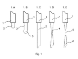
- Figure 1 shows the initial stages of the droplet formulation process.
- Fig 1A shows the initial stage of a droplet emerging from a nozzle tip 1 which can be modelled as cylinder of liquid 2 emerging from the nozzle tip 1. This is shown in Fig. 1A.
- Fig. 1B shows the frontal end of the cylinder 2 forming a sphere-like shape 3.
- Fig. 1C shows the cylinder of liquid as it continues to exit from the nozzle tip 2. The sphere-like shape at the end of the cylinder is not shown in this diagrammatic representation.
- a constriction 4 develops along the cylinder in the vicinity of the nozzle tip 1 ( Fig. 1D ).
- the constriction 4 breaks up at the location indicated by the numeral 5 and the jet is separated from the nozzle ( Fig. 1E ).
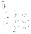
- Fig. 2 The evolution of the jet as it travels away from the nozzle is schematically indicated in Fig. 2 .
- Multiple constrictions develop along the jet as shown in Fig. 2A .
- These constrictions are indicated by the numerals 4a, 4c.
- Fig 2A shows the case of two constrictions being developed.
- the constrictions represent instability in the continuous jet.
- number 9 is an approximation resulting from analytical models.
- These constrictions separate the jet into the droplets indicated by the numerals 6a, 6b, 6c, etc having the separation between the consecutive droplets of approximately 9R o .
- This formula is suitable for liquids of low viscosity ⁇ .
- other formulas need to be used to describe t breakup .
- the droplets will not immediately acquire the spherical shape. Instead they will gradually become more spherical by expanding their cross-section in the plane orthogonal to the travel direction and reducing their length along the travel direction.
- the droplets oscillate and change from the elongated spheroids as shown in Fig. 2B by the numerals 6a, 6b, 6c to the contracted spheroids as shown in Fig. 2C and vice versa. After a number of oscillations they will settle to a sphere-like shape and then continue maintaining this shape until they reach the destination substrate provided it is located close enough. If the destination substrate is located far away, then the evolution of the jet will continue further, the separations between the spherical drops will change and some of them may collide and others may start moving in directions away from the overall jet trajectory. This further evolution of the jet is not shown in Fig. 2 .
- the dynamics of the shape evolution of the droplets is defined by the droplet volume, velocity, surface tension of the liquid ⁇ , its viscosity ⁇ , its density ⁇ , diameter of the nozzle and other factors. Therefore the dynamics of droplet formation differs significantly between the field of use of the present invention, i.e. liquid handling for the medical diagnostics, drug discovery, life science research and droplet formation in ink jet printing.
- the present invention is directed to the specific pathway of the droplet shape evolution related to the specific field of use. This is characterised generally by the volume of the liquid dispensed of 20 nm or greater and the diameter of the nozzle of 80 micrometer or greater, the droplet velocity of in the range of 0.1 m/s to 50 m/s. Furthermore, the present invention is directed to a range of typical liquids used in medical diagnostics, pharmaceutical applications, life science research, genomics, proteomics and drug discovery process.
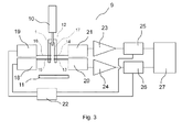
- Fig. 3 shows a schematic diagram of the instrument 9 for measurements of the droplet volume according to one embodiment of the present invention.
- the dispensing device is shown by reference numeral 10.
- the dispensing device as described in the US patents No. 6,713,021 (Shvets ) and No. 6,669,909 (Shvets ) may be used.
- This device is based on the proprietary SpotOn TM technology.
- the device is capable of dispensing a variety of liquids with different mechanical and optical properties in the volume range from 20 nl to well over 100 microlitres.
- the nozzle 1 of the dispensing tip is circular and has cross-section of 0.152 mm.
- the invention is not limited to this specific type of dispensing device or dispensing technology.
- the dispensers utilizing a solenoid valve or micro-solenoid valve is another possible choice of dispensing device for use with the present invention.
- Another suitable example of dispensing device is an instrument utilizing automated syringes.
- the dispensing device delivers droplet to a destination substrate 11.
- the destination substrate could be a microtiter plate or well plate or any other substrate or surface.
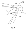
- An optical housing unit 12 is positioned in the vicinity of the nozzle 1. The optical housing 12 unit is described in greater detail in Figs. 4 and 5 .
- the optical housing unit 12 shown in Figs. 4 and 5 is capable of accommodating two pairs of optical fibers. Embodiments could be readily devices that accommodate three, four, five, six or indeed greater number of fibers. As it will be clear from the description below in some embodiments the optical housing unit may also accommodate just one pair of optical fibers, e.g. fibers 13 and 15. The optical fibers coupled into the unit are indicated by numerals 13, 14, 15, 16. In the embodiment described herein optical fibers have core diameter of 1 mm and outer jacket of 2.2 mm. Optical fibers with other core and jacket diameter values could be used as well. The optical fibers are fixed in the body 17 of the optical housing unit either by means of adhesive or by other suitable means, e.g. tight fit.
- the angle between the fibers 13 and 15 is ⁇ . This angle could be equal to the angle between the fibers 14 and 16 or alternatively in other embodiments it could also be different.
- Figure 4 we will refer to the case when the fibers 13 and 14 enter into the body 17 of the optical housing unit parallel to each other as well as the optical fibers 15 and 16.
- all the fibers 13, 14, 15, 16 are orthogonal to the axis of the body 17 of the housing unit. This is more clearly shown in Fig. 5 picturing the optical housing unit 12 from a different viewpoint. It should be appreciated that both pairs of optical fibers 13 and 14 and optical fibers 15 and 16 do not have to be parallel to each other.
- the separation between the end of the fibers 13, 14, 15, 16 and line of the path of the droplet is in the range of 0.1 to 10 mm. This separation is optimized experimentally and it depends on the type of the fibers used and their numerical aperture. Furthermore, the separation between the path of the jet and the end of the fiber 13 does not have to be equal to the same for the fiber 15. The same applies to the fibers 14 and 16.
- the device may have an optical housing unit with an asymmetric body 17.
- the body 17 of the optical housing unit may be made of plastic, metal or another suitable material.
- the body 17 of the housing unit 12 is made in such a way that the droplets preferably travel in front of the ends/terminations of the optical fibers 13, 14, 15, 16.
- the angle ⁇ between the fibers 13 and 15 and the fibers 14 and 16 could be altered. This is shown by cross-sections through the body of the optical housing unit 12 ( Figs. 6A and 6B ).
- optical fibers in this embodiment are located in such a way that the fibers 14 and 16 are located at the same distance away from the nozzle 1. Likewise, the fibers 13 and 15 are located at the same distance away from the nozzle 1. Other embodiments of this device may be contemplated.
- the separation between the optical fibers 13 and 14 and the fibers 15 and 15 is 2 mm as shown in Fig. 6 . Again, embodiments with other separations could be contemplated. In the embodiment described here the separation between the ends of the fibers 14 and 16 and the nozzle 1 is 0.3 mm.
- optical fibers 15 and 16 are coupled into light sources 18 and 19.
- two light-emitting diodes LED SFH756V are employed as the light sources 18 and 19.
- the dominant radiation light wavelength is 660nm. Therefore, the light from the light source can be delivered into the optical fibers 15 and 16 and then towards the ends of the fibers facing the droplet's path.
- the optical fibers 13 and 14 are coupled into detectors 20 and 21.
- SFH250V PIN diode were employed as detectors 20 and 21. This selected diode is sensitive to the light at approximately 660nm wavelength. Both selected devices, the LED and the PIN diode, are suitable for work with fiber and have packaging convenient for coupling to the fiber.
- Reference numeral 22 indicates the phase and frequency modulation unit. This is the unit capable of generating two signals at frequencies f 1 and f 2 and another two signals with the same frequencies f 1 and f 2 but phases offset by the desired phase shifts: ⁇ 1 and ⁇ 2 .
- phase and frequency modulation unit employed digital phase controller utilizing the advanced event module build-in the TMS320F2812 DSP microcontroller. It will be understood that other devices could be employed to construct the phase and frequency modulation unit 22, for example it could be based on analogue circuits.
- the settings of the TMS320F2812 DSP microcontroller are controlled by RS232 interface. The resolution of frequency setting is 1 Hz and 1 ° for phase.
- Reference numerals 23 and 24 are amplifiers and 25 and 26 indicate phase-sensitive detectors, known also as lock-in amplifiers.
- the phase and frequency modulation unit 22 modulates the light emitted by the light sources 18 and 19 as shown schematically in Fig. 3 .
- the unit 22 also supplies the reference signal to the phase-sensitive detectors 25 and 26. Therefore, the remaining two signals produced by the modulation unit 22 shifted by phases ⁇ 1 and ⁇ 2 are supplied to the phase-sensitive detectors 25 and 26.
- the signal from the phase sensitive detector 25 and 26 is supplied to the signal processing unit 27.
- the detailed diagram of the entire circuit is shown in Fig. 7 .
- the diagram shows the layout for a single channel e.g. fibers 14 and 16, and a pair of one light source and one detector.
- Amplifier IC1 is transimpedance amplifier (OPA380). There is high-pass filter installed in between the amplifiers IC1 and IC2 to reject low frequency noise coming from the external light sources (e.g. 100 Hz to 240 Hz). The signal from the output of the phase detector IC3 is filtered by 5 th order low-pass filter based on IC7A, IC7B, IC7C, IC7D utilizing OPA4277 amplifiers. The frequency modulation unit 22 is not shown in Fig. 7 .
- the modulation frequency used in the experiments described below is in the range of 80-100 kHz and the detection low-pass filter has a corner frequency (3dB decay frequency) in the range of 2.5-4 kHz. This frequency is adequate for the detection of the droplets dispensed for many applications in the field of the invention. The higher the speed of the droplets, the faster should be the detection circuit.
- the signal processing unit was a two channel oscilloscope, e.g. Agilent 54622D two-channel oscilloscope, connected to a PC for data acquisition, storage and analysis. It should be stressed that the circuit presented in Fig. 7 is an example of one embodiment only. Other circuits with similar functionalities could be readily designed by those skilled in the art of circuit design.
- the phase shifts between the modulation signal sent to the light source power supply circuit and the reference signal sent to the phase detector ⁇ 1 and ⁇ 2 were 125° and 123° respectively.
- the phase shifts and the frequencies were optimized experimentally to increase the signal-to-noise ratio.
- the positions of the fibers 13, 14, 15 and 16 were adjusted in the body of the housing unit 17 by moving them in and out from the path of the passing droplet.
- the purpose of the adjustment was to optimize the signal-to-noise ratio of the instrument 9 for the detection of the droplet volume. Typically the adjustment was done for just one liquid, e.g. distilled water and was not altered for other liquids. The length of the fibres 13, 14, 15, 16 was some 0.7 m.
- the phase shifts between the modulation signal sent to the light source power supply circuit and the reference signal sent to the phase detector ⁇ 1 and ⁇ 2 were 15° and 13° for the detectors 20 and 21 respectively.
- SF v H - v L v L ⁇ 100 %
- v L is an output signal level (voltage) without a droplet
- v H is an output signal level (voltage) with droplet (saturation value).
- Saturation value means here not the saturation voltage output of the phase sensitive amplifier but rather voltage output of the amplifier in the middle of the droplet passing in front of the fibers 13, 14, 15, 16. The meaning of the saturation value will be further explained by the discussion related to Figs. 21 , 22 .
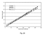
- This signal factor is an indication of a ratio between useful (working) signal and background signal. The higher is SF, the better the signal is. The results are presented in Table 1.
- the second factor given in Table 1, SF/SF water characterizes the ratio of the output signal for a particular testing liquid to the output signal for distilled water (reference liquid).
- Table 1 Summary of the assessment for the output signal Angle ⁇ Liquid SF[%] SF/SF water [%] 45° Distilled Water 125 100 Color Dye 78 62 DMSO 100 80 PBS 115 92 90° Distilled Water 313 100 Color Dye 99 31 DMSO 400 128 PBS 281 90 135° Distilled Water 137 100 Color Dye 110 80 DMSO 163 119 PBS 134 98 180° Distilled Water 15 100 Color Dye 24 154 DMSO 17 108 PBS 18 118
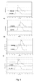
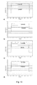
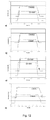
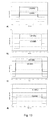
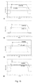
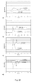
- Figs. 8 to 20 demonstrate how droplet dispensing can be readily registered by the device of the present invention.
- the method for actual measuring of droplet volume on the basis of these results.
- the shape of the droplet dispensed evolves as the droplet travels between the nozzle of the dispenser and the destination substrate.
- the optical fibers 13, 14, 15, 16 should be located at such a distance from the nozzle tip 1 that when droplet passes through the area sensed by the fibers, in its development it is either represented by the state A-A or by state B-B or it is located in any stage of development from the state A-A to the state B-B.
- the droplet In the state A-A the droplet can be represented essentially as a continuous cylindrical segment.
- the droplet In the state B-B the droplet can be represented by a train of sub-droplets of substantially similar size moving at substantially equal separation along the same path provided that separation between the individual droplets is smaller than size of the sensing area of the optical fibers.
- the state A-A or state B-B or any intermittent state reflecting the evolution between these two states as the quasi-cylindrical jet or quasi-cylindrical segment.
- the area the fibers can sense corresponds to their optical aperture.
- the droplet does not form an ideal cylindrical segment at any distance from the nozzle 1.
- the ideal cylinder shape will be always distorted due to the oscillations in the droplet and the effect of the forces of surface tension which lead to the deviation from the ideal cylinder shape.
- the droplet indeed forms at least a distorted cylindrical segment up to some distance away from the nozzle. This can be explained in terms of Fig. 2 .
- FIG. 2A represents a distorted cylinder and this can be associated with the stage A-A of its development.
- the droplet shown in Fig. 2B represents the state B-B according to the definition above.
- the droplet in Fig. 2B moved further away from the nozzle.
- the front of the droplet is represented by the state B-B and the end is by the state A-A.
- the term "quasi-cylindrical" used in this specification covers liquids dispensed from circular and non-circular nozzles.
- the nozzle may have an opening of square cross-section, rectangular cross-section, oval cross-section or indeed any other cross-section.
- a circular cross-section is the most practical one for use in many situations as capillaries of circular cross-section are readily available from numerous manufacturers of capillaries.
- the circular cross-section is easy to analyze due to its rotational symmetry. However, even if the jet is ejected from a non-circular nozzle, it will evolve to the circular cross-section due to action of surface tension as it travels away from the nozzle.
- Formula t breakup k( ⁇ R o 3 / ⁇ ) 1 ⁇ 2 described above suggests the time required for the droplet to evolve from the state A-A to the state B-B. Therefore, if the distance from the nozzle end 1 to the region sensed by the fibers 13, 14, 15, 16 is smaller than t Breakup *V J , where V J is the velocity of the droplet, then it arrives to the sensing area substantially in the state A-A. It is difficult to give analytical formula for the time that the droplet remains in the state B-B. This depends on its velocity and radius of the sub-droplets. However, it is easy to see experimentally if the droplet has evolved past the state B-B by the time it has arrived to the sensing area. This is explained in detail further on.
- the velocity V J depends on the type of the dispensing instrument used. For example, in the case of the dispensing instrument as described in the US patents No. 6,713,021 (Shvets ) and No. 6,669,909 (Shvets ), the velocity is determined by the inner diameter of the nozzle, its length, the pressure in the dispenser and the viscosity of the liquid dispensed. For a typical practical dispenser utilising the concept described in the US patents No. 6,713,021 (Shvets ) and No. 6,669,909 (Shvets ), the velocity is in the range of 0.1 to 20 m/sec.
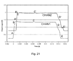
- the stage representing the passing of the ball-like forehead through the sensing area of the fibers 13, 14, 15, 16 is marked by letters B, B' in Figs. 21 and 22 .
- the jet is fully positioned in the sensing area of the fibers, i.e. spreads through the entire aperture of the fibers 13, 14, 15, 16, the signal is saturated.
- This stage is marked by letters C, C' in Figs. 21 and 22 .
- the valve or another mechanism controlling the dispensing is closed, the supply of liquid to the nozzle discontinues and the jet narrows down as shown in Fig. 1D . This results in a signal drop. By comparison to the signal rising slope, the rate of this signal drop is usually relatively slow.
- This stage is marked by letters D, D' in Figs. 21 and 22 .
- the jet breaks away from the nozzle. This is seen in the signal stage marked by letters E, E' in Figs. 21 and 22 .
- the process of separation of the jet from the nozzle often has somewhat random character and often minute droplets are formed at the location where the jet is separated from the nozzle 1.
- these tiny droplets may return back to the nozzle, i.e. they may travel in the direction opposite to the jet. In some cases they follow the main jet as separate droplets and in some cases they travel faster than the main jet and therefore, catch up with the jet tail.
- spurious signal, small signal peaks, etc as marked by letters E, E' in Figs. 21 and 22 .
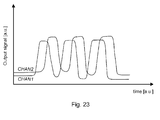
- This figure shows the segment of jet separated into three separate sub-droplets passing in front of the optical fiber.
- the sensing area of the fiber is reduced to capture just a single droplet at a time.
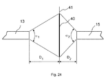
- the size of the sensing area of the fibers depends of the numerical aperture of the fibers and the separation between their ends. This is schematically shown in Fig. 24 .
- the size of the sensing area can be increased if the separation between the ends of the fibers is increased or if the fibers with greater numerical aperture are used. This will be clear to those skilled in fiber optics.
- the numerical aperture of the fibers 13 and 15 is indicated schematically by letters ⁇ 1 and ⁇ 2 .
- the size of the sensing area is indicated by the numeral 40.
- Line 41 indicates the trajectory of the passing jet.
- the separations from the ends of the fibers 13 and 15 to the line 41 are indicated by the letters D 1 and D 2 .
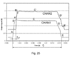
- the first embodiment of the method is based on measurement of the jet length I j . It is explained with reference to Fig. 25 .
- the jet in the typical volume range of interest to the field of the invention can be represented as a cylindrical segment.
- the diameter of the jet 2R 0 (twice the radius) is typically essentially equivalent to the inner diameter ( 2r ) (twice the radius) of the nozzle and it is uniform throughout the length of the jet segment.
- the cross-sectional area of the jet is ⁇ R 0 2 .
- t j is the time required for the jet segment to pass in front of the optical fiber, e.g. fiber 14 or fiber 13
- v j is the velocity of the jet.
- the velocity of the jet can be calculated from the time delay t f-f between the fronts A and A' and the separation I f-f between sensing areas of the optical fibers 13 and 14.
- the velocity of the jet forehead can fairly represent velocity of the entire jet.
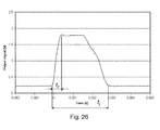
- the second embodiment of the method is explained with reference to Fig. 26 .
- the measurement is based on the signal from the output of a single phase sensitive detector 26.
- the signal from the second phase sensitive detector 25 is not required for this embodiment. Therefore this embodiment is based on just one set of fibers, e.g. 15 and 13 (or equally, fibers 14 and 16), one light source and one light detector.
- the jet length is determined as above using the value of the time t j .
- t r and t j are schematically indicated in Fig. 26 . Again we do not discuss the methods for the extraction of the values of t r and t j from the signal profile. The extraction could be achieved by means of analogue circuits, e.g. integrating and differentiating circuits or by means of conversion of the signal into digital form and then processing it. These will be well known to those skilled in the art.
- the droplet may split into a train of sub-droplets (quasi-cylindrical) and it can still produce a signal when passing in front of the optical fibers 13, 14, 15, 16 at the phase sensitive detectors 25, 26 as if it were a continuous jet segment. This is provided that a number of such sub-droplets appear in the sensing area of the fibers simultaneously. This observation forms one of the key aspects and unexpected findings of the present invention.
- Such a state of the droplet is called in the invention state B-B.
- the droplet passes the sensing area of the first set of fibers 16 and 14 as a continuous jet, i.e.
- the invention demonstrates that such a transition does not affect the signal too much although the accuracy of measurements is somewhat compromised. This is well illustrated by data presented in Figs. 8-22 .
- the signal from the Channel 2 (phase sensitive detector 26) generally mimics rather closely the signal from the Channel 1 (phase sensitive detector 25). However, the signal of the Channel 2 is noisier and for some dispensing volumes it may contain spurious peaks.
- the size of the sensing area of the fibers is some 2 mm in diameter. Generally for the droplets ejected from the nozzle of 150 micron internal diameter there are some 3-4 droplets appearing in the sensing area at any given moment during the dispensing. This is because the separation between the sub-droplets in this case is some only 0.6-0.8 mm.
- the third embodiment of the method is also based on the signal from the output of a single phase sensitive detector, e.g. detector 26.
- velocity of the jet is measured by means of the time delay t d between the start of the dispensing and the moment when the jet's forehead is detected by the detector 26.
- the length l j of the jet is defined from the value of time t j as in the second embodiment.
- the embodiment could be altered as follows as explained with reference to Fig. 27 .
- the signal from the phase-sensitive detector is measured for a given position of the nozzle. This is represented by the curve F in Fig. 25 .
- the nozzle is displaced essentially along the direction of the jet trajectory by a certain distance ⁇ D .
- the identical jet is then dispensed again and the signal is recorded for the second time. This is represented by the curve F'.
- the two curves are essentially identical curves and one of them being merely displaced along the x-axis of the graph in Fig. 27.
- Fig. 27 shows the case when the nozzle was displaced away from the fiber for the second dispensing indicated by the curve F'.
- the scaling factor Ks can be determined from the calibration of the device using a separate volume measurements device, e.g. micro balance.
- the invention does not need to be used with the nozzles of cylindrical shape. If the nozzle is not of cylindrical shape, then in the formulas for the droplet volume we need to substitute the cross-sectional area of the nozzle instead of the value ⁇ r 2 .
- the diameter of the jet in the state A-A is not necessarily equal to the inner diameter of the nozzle even though the two values are usually rather close.
- the diameter of the jet was calculated to be 0.180 mm whereas the internal diameter of the nozzle was 0.152 mm.
- Our experiments suggest that the diameter of the jet is in between the values of the inner and outer diameters of the nozzle. The greater is the jet velocity; the closer is the diameter of the jet to the inner diameter of the nozzle.
- the difference between the inner diameter and the jet diameter also depends on the surface tension ⁇ of the liquid dispensed. Therefore in general when using the embodiments 1, 2, 3 of the method for the droplet measurements described above, it is beneficial to evaluate the diameter of the jet on the basis of the direct volume calibration.
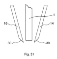
- Fig. 30 shows element of another possible embodiment of the device 9. It shows the positions of the optical fibers 13, 14, 15 and 16. All the other elements of the device are similar to the ones described with reference to Fig. 4 .
- the ends of the fibers 13, 14, 15, 16 are aligned substantially along the pathway of the jet.
- the figure 30 shows the embodiment then they are actually aligned parallel to the pathway of the jet.
- the fibers could also form angle with the pathway of the jet as shown in Fig. 31 .
- the ends of the fibers are cut in such a way that they form surface tilted with respect to its axis.
- the end of the fiber is treated so that it forms preferably reflective surface marked by numeral 30.
- Fig, 30 shows embodiment when the fibers 13 and 14 are positioned on one side of the nozzle 1 and the fibers 15, 16 are directly on the opposite side. This is done only for the simplicity of the figure.
- the all the fibers 13, 14, 15, 16 do not need to be positioned the same distance away from the nozzle. This is done merely for simplicity of the figures 30 and 31 .
- the light from the fiber 15 is coupled into the fiber 13 via the jet meaning that the amount of light coupled is altered when the jet is passing in the vicinity of the ends of the fibers.
- the fibers 16 and 14 the light from the fiber 16 is coupled into the fiber 14 via the jet.
- the presence of the reflective surfaces at the ends of the fibers 13, 14, 15, 16 increases the efficiency of the coupling.
- the operation of this embodiment is similar to the one described with reference to Fig. 3 .
- phase-sensitive detectors do not have to be used.
- the wavelength of light coupled into the fibers 15 and 16 could be different. This increases the complexity of the system but reduces the cross-talk between the pairs of fibers so that the signal coupled into the fiber 14 from the fiber 15 as well as the signal coupled into the fiber 13 from the fiber 15 is minimized.
- the filters need to be used. For example, if the light coupled into the fibers 15 and 16 is at the wavelengths ⁇ 1 and ⁇ 2 then band-pass filters could be installed at the output of the fibers 13 and 14 that transmit the light at the wavelengths ⁇ 1 and ⁇ 2 respectively. This ensures for example that the light from the fiber 15 is coupled into the fiber 13 but not into the fiber 14.
- embodiment of the device could be constructed in which detection of the droplet takes place simultaneously for several angles ⁇ . This increases complexity of the instrument but in some cases may lead to improved accuracy and robustness of the droplet measurements.
- embodiment could be constructed having two fibers 14' and 14" coupled to the fiber 16. The angle ⁇ between the fibers 16 and 14' could be 180° and the angle ⁇ between the fibers 16 and 14" could be 90°.
- other values of the angles could be chosen. In this case two sets of amplifiers and filters may need to be used. This could be marked with numerals 21', 21 ", 23', 23", 25', 25".
Applications Claiming Priority (1)
| Application Number | Priority Date | Filing Date | Title |
|---|---|---|---|
| IE20060943 | 2006-12-21 |
Publications (1)
| Publication Number | Publication Date |
|---|---|
| EP1946843A1 true EP1946843A1 (fr) | 2008-07-23 |
Family
ID=39145393
Family Applications (1)
| Application Number | Title | Priority Date | Filing Date |
|---|---|---|---|
| EP07123872A Withdrawn EP1946843A1 (fr) | 2006-12-21 | 2007-12-20 | Procédé et appareil de surveillance et de mesure de gouttelettes |
Country Status (2)
| Country | Link |
|---|---|
| US (1) | US8420014B2 (fr) |
| EP (1) | EP1946843A1 (fr) |
Cited By (6)
| Publication number | Priority date | Publication date | Assignee | Title |
|---|---|---|---|---|
| WO2017060335A1 (fr) * | 2015-10-09 | 2017-04-13 | Vermes Microdispensing GmbH | Système de guide optique pour la détection optique de gouttes |
| DE102016114607A1 (de) * | 2016-08-05 | 2018-02-08 | Infineon Technologies Ag | Flüssigkeitsabgabesystem, -Vorrichtung und -Verfahren |
| WO2018153997A1 (fr) | 2017-02-24 | 2018-08-30 | Vermes Microdispensing GmbH | Système de guidage pour des dispositifs de détection |
| CN109863407A (zh) * | 2016-10-28 | 2019-06-07 | 贝克顿·迪金森公司 | 正分配验证传感器 |
| US10753850B2 (en) | 2015-10-09 | 2020-08-25 | Vermes Microdispensing GmbH | Drop-detection device |
| US11298701B2 (en) | 2018-11-26 | 2022-04-12 | King Instrumentation Technologies | Microtiter plate mixing control system |
Families Citing this family (11)
| Publication number | Priority date | Publication date | Assignee | Title |
|---|---|---|---|---|
| EP2491405A1 (fr) * | 2009-10-19 | 2012-08-29 | Yeda Research and Development Co. Ltd. | Procédé et système d'analyse d'un liquide |
| EP2704220B1 (fr) * | 2011-04-26 | 2018-03-07 | Sanyu Rec Co., Ltd. | Procédé et appareil de fabrication de dispositif optique |
| KR101477376B1 (ko) * | 2013-03-14 | 2014-12-29 | 삼성전기주식회사 | 유체 토출 장치 |
| JP6639122B2 (ja) * | 2015-07-03 | 2020-02-05 | 東芝デベロップメントエンジニアリング株式会社 | 吐出量測定装置 |
| CA3012489C (fr) * | 2016-02-29 | 2023-01-31 | Ventana Medical Systems, Inc. | Systeme et procede de caracterisation de distribution |
| DE102017207524B4 (de) * | 2017-05-04 | 2020-07-02 | Festo Se & Co. Kg | Dosiervorrichtung und damit ausführbares Dosierverfahren |
| US11788947B2 (en) * | 2018-01-31 | 2023-10-17 | Integrated Dna Technologies, Inc. | System and method for controlling droplet dispensing |
| DE102018202521B4 (de) | 2018-02-20 | 2023-10-19 | Festo Se & Co. Kg | Dosiervorrichtung |
| CN115970784A (zh) * | 2018-07-20 | 2023-04-18 | 布赖顿技术有限责任公司 | 从液体微滴分配系统收集样本确定微滴质量的方法和装置 |
| WO2022169451A1 (fr) * | 2021-02-04 | 2022-08-11 | Hewlett-Packard Development Company, L.P. | Systèmes d'enregistrement de cartouche d'impression |
| CN113484010A (zh) * | 2021-08-10 | 2021-10-08 | 西安工程大学 | 一种辅助喷嘴有效射流体积实验测定方法 |
Citations (16)
| Publication number | Priority date | Publication date | Assignee | Title |
|---|---|---|---|---|
| US4328801A (en) * | 1980-10-30 | 1982-05-11 | Alvin J. Marx | Automated intravenous fluid regulating and administering apparatus |
| US4574850A (en) | 1985-01-17 | 1986-03-11 | E. I. Du Pont De Nemours And Company | Method of and apparatus for dispensing liquid |
| US4936828A (en) * | 1987-06-02 | 1990-06-26 | Kophu Chiang | Liquid drop image sensor |
| US5035150A (en) | 1986-08-14 | 1991-07-30 | Kontron Instruments Holdings, N.V. | Pipetting method |
| US5186057A (en) * | 1991-10-21 | 1993-02-16 | Everhart Howard R | Multi-beam liquid-drop size/rate detector apparatus |
| WO1993009407A1 (fr) * | 1991-10-30 | 1993-05-13 | Roelofs Octrooien En Investeringen B.V. | Procede de mesure du debit d'un liquide, et appareil pour sa mise en ×uvre |
| US5559339A (en) | 1994-10-31 | 1996-09-24 | Abbott Laboratories | Method and apparatus for verifying dispense of a fluid from a dispense nozzle |
| US5741554A (en) | 1996-07-26 | 1998-04-21 | Bio Dot, Inc. | Method of dispensing a liquid reagent |
| US5744099A (en) | 1995-09-15 | 1998-04-28 | Cytek Development Inc. | Apparatus for transfer of biological fluids |
| DE19911400A1 (de) * | 1998-03-13 | 1999-09-23 | Trigate Projects Proprietary L | Infusionszuführsystem |
| US6213354B1 (en) * | 1999-12-29 | 2001-04-10 | Elite Engineering Corporation | System and method for dispensing fluid droplets of known volume and generating very low fluid flow rates |
| EP1099484A1 (fr) | 1999-11-11 | 2001-05-16 | The Provost, Fellows And Scholars Of The College Of The Holy And Undivided Trinity Of Queen Elizabeth Near Dublin | Procédé et appareil de distribution de gouttes |
| US20010050294A1 (en) * | 2000-05-25 | 2001-12-13 | Plattner Edward Michael | Adhesive dispensing and vision system for an automatic assembly system |
| US6669909B2 (en) | 2001-03-26 | 2003-12-30 | Allegro Technologies Limited | Liquid droplet dispensing |
| US20050223814A1 (en) | 2004-02-27 | 2005-10-13 | Igor Shvets | Apparatus and method for droplet measurements |
| WO2006079926A1 (fr) * | 2005-01-31 | 2006-08-03 | Labcoat, Ltd | Procede et systeme de revetement de dispositif medical utilisant une verification optique du volume de gouttes |
Family Cites Families (1)
| Publication number | Priority date | Publication date | Assignee | Title |
|---|---|---|---|---|
| DE60031015T2 (de) * | 1999-02-16 | 2007-05-10 | Applera Corp., Foster City | Vorrichtung zur Handhabung von Kügelchen |
-
2007
- 2007-12-20 EP EP07123872A patent/EP1946843A1/fr not_active Withdrawn
- 2007-12-21 US US11/962,538 patent/US8420014B2/en active Active
Patent Citations (18)
| Publication number | Priority date | Publication date | Assignee | Title |
|---|---|---|---|---|
| US4328801A (en) * | 1980-10-30 | 1982-05-11 | Alvin J. Marx | Automated intravenous fluid regulating and administering apparatus |
| US4574850A (en) | 1985-01-17 | 1986-03-11 | E. I. Du Pont De Nemours And Company | Method of and apparatus for dispensing liquid |
| US5035150A (en) | 1986-08-14 | 1991-07-30 | Kontron Instruments Holdings, N.V. | Pipetting method |
| US4936828A (en) * | 1987-06-02 | 1990-06-26 | Kophu Chiang | Liquid drop image sensor |
| US5186057A (en) * | 1991-10-21 | 1993-02-16 | Everhart Howard R | Multi-beam liquid-drop size/rate detector apparatus |
| WO1993009407A1 (fr) * | 1991-10-30 | 1993-05-13 | Roelofs Octrooien En Investeringen B.V. | Procede de mesure du debit d'un liquide, et appareil pour sa mise en ×uvre |
| US5559339A (en) | 1994-10-31 | 1996-09-24 | Abbott Laboratories | Method and apparatus for verifying dispense of a fluid from a dispense nozzle |
| US5744099A (en) | 1995-09-15 | 1998-04-28 | Cytek Development Inc. | Apparatus for transfer of biological fluids |
| US5741554A (en) | 1996-07-26 | 1998-04-21 | Bio Dot, Inc. | Method of dispensing a liquid reagent |
| DE19911400A1 (de) * | 1998-03-13 | 1999-09-23 | Trigate Projects Proprietary L | Infusionszuführsystem |
| EP1099484A1 (fr) | 1999-11-11 | 2001-05-16 | The Provost, Fellows And Scholars Of The College Of The Holy And Undivided Trinity Of Queen Elizabeth Near Dublin | Procédé et appareil de distribution de gouttes |
| US6713021B1 (en) | 1999-11-11 | 2004-03-30 | The Provost, Fellows And Scholars Of The College Of The Holy And Undivided Trinity Of Queen Elizabeth Near Dublin | Dispensing method and assembly for liquid droplets |
| US20040101445A1 (en) * | 1999-11-11 | 2004-05-27 | Provost, Fellows & Scholars Of College Of Holy & Undivided Trinity Of Queen Elizabeth Near Dublin | Dispensing assembly for liquid droplets |
| US6213354B1 (en) * | 1999-12-29 | 2001-04-10 | Elite Engineering Corporation | System and method for dispensing fluid droplets of known volume and generating very low fluid flow rates |
| US20010050294A1 (en) * | 2000-05-25 | 2001-12-13 | Plattner Edward Michael | Adhesive dispensing and vision system for an automatic assembly system |
| US6669909B2 (en) | 2001-03-26 | 2003-12-30 | Allegro Technologies Limited | Liquid droplet dispensing |
| US20050223814A1 (en) | 2004-02-27 | 2005-10-13 | Igor Shvets | Apparatus and method for droplet measurements |
| WO2006079926A1 (fr) * | 2005-01-31 | 2006-08-03 | Labcoat, Ltd | Procede et systeme de revetement de dispositif medical utilisant une verification optique du volume de gouttes |
Non-Patent Citations (4)
| Title |
|---|
| D. ROSE: "Microdispensing Technologies in Drug Discovery", DRUG DISCOVERY TECHNOLOGY, vol. 4, no. 9, September 1999 (1999-09-01), pages 411 - 419 |
| I. V. SHVETS ET AL.: "Spot on Technology of low volume liquid handling", JOURNAL OF ASSOCIATION OF LABORATORY AUTOMATION, vol. 7, no. 6, December 2002 (2002-12-01), pages 127 - 131 |
| J. COMLEY: "Nanolitre Dispensing - on the Point of Delivery, Drug Discovery World", SUMMER, 2002, pages 33 - 44 |
| S.D. ROSE: "Applications of a Novel Microarraying System in Genomics Research and Drug Discovery", JOURNAL OF THE ASSOCIATION FOR LABORATORY AUTOMATION, vol. 3, no. 3, 1998, pages 53 - 56 |
Cited By (11)
| Publication number | Priority date | Publication date | Assignee | Title |
|---|---|---|---|---|
| WO2017060335A1 (fr) * | 2015-10-09 | 2017-04-13 | Vermes Microdispensing GmbH | Système de guide optique pour la détection optique de gouttes |
| CN108139323A (zh) * | 2015-10-09 | 2018-06-08 | 微密斯点胶技术有限公司 | 用于光学液滴探测的光导体单元 |
| US10753850B2 (en) | 2015-10-09 | 2020-08-25 | Vermes Microdispensing GmbH | Drop-detection device |
| US10809116B2 (en) | 2015-10-09 | 2020-10-20 | Vermes Microdispensing GmbH | Light-guiding element arrangement for optical drop detection |
| DE102016114607A1 (de) * | 2016-08-05 | 2018-02-08 | Infineon Technologies Ag | Flüssigkeitsabgabesystem, -Vorrichtung und -Verfahren |
| US10906057B2 (en) | 2016-08-05 | 2021-02-02 | Infineon Technologies Ag | Liquid-dispensing system, apparatus and method |
| CN109863407A (zh) * | 2016-10-28 | 2019-06-07 | 贝克顿·迪金森公司 | 正分配验证传感器 |
| CN109863407B (zh) * | 2016-10-28 | 2023-05-09 | 贝克顿·迪金森公司 | 正分配验证传感器 |
| WO2018153997A1 (fr) | 2017-02-24 | 2018-08-30 | Vermes Microdispensing GmbH | Système de guidage pour des dispositifs de détection |
| DE102017103876A1 (de) | 2017-02-24 | 2018-08-30 | Vermes Microdispensing GmbH | Führungssystem für Detektionsvorrichtungen |
| US11298701B2 (en) | 2018-11-26 | 2022-04-12 | King Instrumentation Technologies | Microtiter plate mixing control system |
Also Published As
| Publication number | Publication date |
|---|---|
| US20080184809A1 (en) | 2008-08-07 |
| US8420014B2 (en) | 2013-04-16 |
Similar Documents
| Publication | Publication Date | Title |
|---|---|---|
| US8420014B2 (en) | Apparatus and method for monitoring and measurement of droplets | |
| EP1739402B1 (fr) | Procedes de separation, d"identification et d'administration de specimen et dispositif correspondant, et procede de dispositif d"analyse | |
| EP1568415A2 (fr) | Méthode et dispositif pour mesurer les gouttelettes | |
| CN101379386B (zh) | 便携式样品分析仪系统 | |
| CN110770547B (zh) | 测量微小体积液体的方法及装置 | |
| US5452619A (en) | Method for pipetting a blood sample | |
| EP1334770B1 (fr) | Systeme de distribution precise de liquides | |
| US5488874A (en) | Liquid aspirating method | |
| CN101377520B (zh) | 自动分析装置 | |
| JP5336179B2 (ja) | 診断液体の診断試薬の分取 | |
| US10258981B2 (en) | Dispensed liquid measurement device | |
| JP2009522546A (ja) | 使い捨てのカードにおける白血球鑑別 | |
| EP0607442B1 (fr) | Procede de dilution de liquide hautement visqueux | |
| EP1963819A2 (fr) | Systeme d'analyseur portatif d'echantillons | |
| CN111699044B (zh) | 自动化体积测定装置 | |
| US20070109139A1 (en) | Electrical drop surveillance | |
| Bammesberger et al. | Quantitative characterization of non-contact microdispensing technologies for the sub-microliter range | |
| CN103154699A (zh) | 流变测量设备 | |
| Chai et al. | Practical considerations of liquid handling devices in drug discovery | |
| JP2008519280A (ja) | 音響吐出デバイスを用いた実験室デバイス、方法およびシステム | |
| CN110987916B (zh) | 一种微流控芯片及其检测方法 | |
| Knaide et al. | Rapid volume verification in high-density microtiter plates using dual-dye photometry | |
| Lutz et al. | Contact-free dispensing of living cells in nanoliter droplets | |
| US20080084559A1 (en) | Microvolume sampling device | |
| SU1763896A1 (ru) | Способ контрол качества изготовлени выдающей части мерного устройства |
Legal Events
| Date | Code | Title | Description |
|---|---|---|---|
| PUAI | Public reference made under article 153(3) epc to a published international application that has entered the european phase |
Free format text: ORIGINAL CODE: 0009012 |
|
| AK | Designated contracting states |
Kind code of ref document: A1 Designated state(s): AT BE BG CH CY CZ DE DK EE ES FI FR GB GR HU IE IS IT LI LT LU LV MC MT NL PL PT RO SE SI SK TR |
|
| AX | Request for extension of the european patent |
Extension state: AL BA HR MK RS |
|
| AKX | Designation fees paid | ||
| REG | Reference to a national code |
Ref country code: DE Ref legal event code: 8566 |
|
| STAA | Information on the status of an ep patent application or granted ep patent |
Free format text: STATUS: THE APPLICATION IS DEEMED TO BE WITHDRAWN |
|
| 18D | Application deemed to be withdrawn |
Effective date: 20090124 |