EP1943991A1 - Fiber stacking and fiber stacking drum for absorbent, manufacturing method for absorbent using the same, and absorptive article having absorbent manufactured by the method - Google Patents
Fiber stacking and fiber stacking drum for absorbent, manufacturing method for absorbent using the same, and absorptive article having absorbent manufactured by the method Download PDFInfo
- Publication number
- EP1943991A1 EP1943991A1 EP06810835A EP06810835A EP1943991A1 EP 1943991 A1 EP1943991 A1 EP 1943991A1 EP 06810835 A EP06810835 A EP 06810835A EP 06810835 A EP06810835 A EP 06810835A EP 1943991 A1 EP1943991 A1 EP 1943991A1
- Authority
- EP
- European Patent Office
- Prior art keywords
- absorbent body
- fiber accumulating
- drum
- fiber
- sucking
- Prior art date
- Legal status (The legal status is an assumption and is not a legal conclusion. Google has not performed a legal analysis and makes no representation as to the accuracy of the status listed.)
- Granted
Links
Images


Classifications
-
- A—HUMAN NECESSITIES
- A61—MEDICAL OR VETERINARY SCIENCE; HYGIENE
- A61F—FILTERS IMPLANTABLE INTO BLOOD VESSELS; PROSTHESES; DEVICES PROVIDING PATENCY TO, OR PREVENTING COLLAPSING OF, TUBULAR STRUCTURES OF THE BODY, e.g. STENTS; ORTHOPAEDIC, NURSING OR CONTRACEPTIVE DEVICES; FOMENTATION; TREATMENT OR PROTECTION OF EYES OR EARS; BANDAGES, DRESSINGS OR ABSORBENT PADS; FIRST-AID KITS
- A61F13/00—Bandages or dressings; Absorbent pads
- A61F13/15—Absorbent pads, e.g. sanitary towels, swabs or tampons for external or internal application to the body; Supporting or fastening means therefor; Tampon applicators
- A61F13/15577—Apparatus or processes for manufacturing
- A61F13/15617—Making absorbent pads from fibres or pulverulent material with or without treatment of the fibres
- A61F13/15658—Forming continuous, e.g. composite, fibrous webs, e.g. involving the application of pulverulent material on parts thereof
-
- A—HUMAN NECESSITIES
- A61—MEDICAL OR VETERINARY SCIENCE; HYGIENE
- A61F—FILTERS IMPLANTABLE INTO BLOOD VESSELS; PROSTHESES; DEVICES PROVIDING PATENCY TO, OR PREVENTING COLLAPSING OF, TUBULAR STRUCTURES OF THE BODY, e.g. STENTS; ORTHOPAEDIC, NURSING OR CONTRACEPTIVE DEVICES; FOMENTATION; TREATMENT OR PROTECTION OF EYES OR EARS; BANDAGES, DRESSINGS OR ABSORBENT PADS; FIRST-AID KITS
- A61F13/00—Bandages or dressings; Absorbent pads
- A61F13/15—Absorbent pads, e.g. sanitary towels, swabs or tampons for external or internal application to the body; Supporting or fastening means therefor; Tampon applicators
- A61F13/15577—Apparatus or processes for manufacturing
- A61F13/15617—Making absorbent pads from fibres or pulverulent material with or without treatment of the fibres
- A61F13/15626—Making fibrous pads without outer layers
-
- A—HUMAN NECESSITIES
- A61—MEDICAL OR VETERINARY SCIENCE; HYGIENE
- A61F—FILTERS IMPLANTABLE INTO BLOOD VESSELS; PROSTHESES; DEVICES PROVIDING PATENCY TO, OR PREVENTING COLLAPSING OF, TUBULAR STRUCTURES OF THE BODY, e.g. STENTS; ORTHOPAEDIC, NURSING OR CONTRACEPTIVE DEVICES; FOMENTATION; TREATMENT OR PROTECTION OF EYES OR EARS; BANDAGES, DRESSINGS OR ABSORBENT PADS; FIRST-AID KITS
- A61F13/00—Bandages or dressings; Absorbent pads
- A61F13/15—Absorbent pads, e.g. sanitary towels, swabs or tampons for external or internal application to the body; Supporting or fastening means therefor; Tampon applicators
- A61F13/53—Absorbent pads, e.g. sanitary towels, swabs or tampons for external or internal application to the body; Supporting or fastening means therefor; Tampon applicators characterised by the absorbing medium
- A61F13/531—Absorbent pads, e.g. sanitary towels, swabs or tampons for external or internal application to the body; Supporting or fastening means therefor; Tampon applicators characterised by the absorbing medium having a homogeneous composition through the thickness of the pad
Definitions
- An absorbent body K' fabricated in the fiber accumulating drum 210 is transferred onto the top surface of crepe paper 250 conveyed on a vacuum conveyer by suction with a sucking device 249 and directly sent to a downstream processing step while being conveyed on the conveyer.
- Patent Document 1 does not have a mechanism for flow-adjusting vacuum air by sucking means, and thus, vacuum air is left to be in an eddy flow. Because of this, it is configured so that the vacuum air is made to approach a rectified flow to suppress the deviation of the weight of the absorbent body by a method for decreasing step by step the diameter of a sucking pore of a mesh in a transverse direction.
- a sucking pore clogging of fluff pulp and high water absorptive polymer to its mesh is liable to occur, whereby the profile of the absorbent body becomes unstable.
- a first primary object of the present invention is to solve the above problem and thus is to provide a fiber accumulating apparatus for an absorbent body for stabilizing the profile of an absorbent body to thereby suppress the deviation of the absorbent body weight, a method for manufacturing an absorbent body using the apparatus, and an absorbent article having an absorbent body produced by the manufacturing method.
- the invention described in claim 3 is the fiber accumulating apparatus for an absorbent body described in claim 1 or 2, wherein the sucking pores of the perforated plate are formed in a cone shape toward the internal side from the external side.
- the pore size of the sucking pore on the external side is set to be 0.5 mm or less (excluding 0 mm) and the pore size on the internal side is smaller than the pore size on the external side.
- setting the opening ratio of a sucking pore on the external side to 30% or more and thus increasing the number of pores per area renders a polymer to be hardly clogged, thereby being capable of suppressing the generation of fiber accumulation failure.
- a convex member is detachably provided, the production is possible in such a manner that the convex member is disposed only during the production of an absorbent body having a concave portion or the like, so that the general purpose properties of the fiber accumulation apparatus can be ensured. Moreover, an appropriate alteration of the position of a convex member enables the position of a concave portion or the like in an absorbent body to be changed.
Abstract
Description
- The present invention relates to a fiber accumulating apparatus and a fiber accumulating drum, for an absorbent body used for a paper diaper, a sanitary napkin and the like, a method for manufacturing an absorbent body using the same, and an absorbent article having an absorbent body manufactured by the method.
- Absorbent bodies for absorbing urine, feces, menses or the like are used for absorbent articles such as paper diapers and sanitary napkins, and the absorbent body is formed by accumulation of fluff pulp and high water absorptive polymer.
- The absorbent body is manufactured, for example, by an absorbent body manufacturing apparatus illustrated in
FIG. 1 . The absorbent body manufacturing apparatus includes afluffer 51 for finely pulverizing a pulp material to be supplied, acasing 52 for surrounding thefluffer 51 and also conveying a pulverized fluff pulp using air, and afiber accumulating apparatus 53 disposed in an opening downstream of thecasing 52. - Among these, the
fiber accumulating apparatus 53, as shown inFIG. 2 , includes afiber accumulating drum 30 including amesh 32 having a large number of sucking pores formed in its outer peripheral surface and asucking chamber 31 disposed on internal side of thefiber accumulating drum 30. The inside of thesucking chamber 31 is maintained at a negative pressure by sucking means (not shown) to thereby accumulate the fluff pulp conveyed by air on themesh 32. Themesh 32 is attached to a reinforcingring 34 and an absorbent body raw material S made of fluff pulp and high water absorptive polymer is accumulated in a concave portion having, as side portions,pattern rings fiber accumulating drum 30 in a transverse direction and themesh 32 as a bottom portion. - In addition, the
casing 52 is provided with apolymer loading port 54 for feeding powdered particulates of the high absorptive polymer together with the fluff pulp. Below thefiber accumulating drum 30, as shown inFIG. 1 , provided is aconveyer 55 with a sucking device that transfers and conveys an absorbent body adsorbed on and held by thefiber accumulating drum 30. - Here,
Patent Document 1 describes a fiber accumulating drum that suppresses the deviation of the weight of an absorbent body by means of sucking means in association with vacuum air (see Patent Document 1). - Absorbent bodies for absorbing urine, feces, menses or the like are used for absorbent articles such as paper diapers, sanitary napkins and wipes. Such an absorbent body is produced by a
manufacturing apparatus 201 illustrated, for example, inFIG. 15 . The manufacturing apparatus for an absorbent body includes afluffer 204 for finely pulverizing apulp material 200 to be supplied, a fluffpulp feeding casing 208 for surrounding the fluffer, and afiber accumulating drum 210 disposed in an opening downstream of the fluffpulp feeding casing 208. The fluffpulp feeding casing 208 constitutes the exterior cladding of a chamber C for conveying on an air flow the pulverized fluff pulp to the outer peripheral surface of the downstream fiber accumulating drum. - The fluff
pulp feeding casing 208 includes apolymer loading port 206 for feeding an absorptive polymer other than the fluff pulp into the chamber. In addition, thefiber accumulating drum 210 has , at appropriate intervals in its outer peripheral surface, absorbent body-forming air-permeable concave portions . Entire surface of each concave portion is made of a fine mesh or is provided with many fine pores. Thefiber accumulating drum 210 is configured so as to accumulate the fluff pulp air-conveyed in the absorbent body-forming concave portion while the fluff pulp is mixed with the absorptive polymer by maintaining the inside of thefiber accumulating drum 210 at a negative pressure by means of sucking means (not shown). - An absorbent body K' fabricated in the
fiber accumulating drum 210 is transferred onto the top surface ofcrepe paper 250 conveyed on a vacuum conveyer by suction with a suckingdevice 249 and directly sent to a downstream processing step while being conveyed on the conveyer. - Here, for the purpose of improvement of absorption performance or anti-leak performance in an absorbent body for absorbing urine, feces, menses or the like, used for absorbent articles particularly such as paper diapers and sanitary napkins, when the absorbent body is used as a product, an absorbent body having a concave portion corresponding to a urination organ, a defecation organ or the like or a hole-made absorbent body having a hole portion corresponding to a defecation organ or the like may be frequently used.
- Such an absorbent body or the like having a concave portion has been conventionally manufactured as follows. For example, a an absorbent body-forming concave portion of a fiber accumulating drum is sealed partly using an adhesive sheet such that fluff pulp or the like is not accumulated only there; a cone-shaped concave portion or the like is formed in an accumulated absorbent body with a convex portion such as a substantially dome protruded to a drum outer peripheral surface side by partly press molding an absorbent body-forming concave portion of the fiber accumulating drum; or alternatively, a cone-shaped concave portion or the like is formed in an accumulated absorbent body with a convex portion protruded to a drum outer peripheral surface side by partly weld-bonding a substantially bowl-shaped member to an absorbent body-forming concave portion of the fiber accumulating drum (see Patent Document 2).
Patent Document 1: Japanese Patent Laid-Open No.2004-2227774
Patent Document 2: Japanese Patent Laid-Open No.2002-272782 - The invention described in
Patent Document 1 does not have a mechanism for flow-adjusting vacuum air by sucking means, and thus, vacuum air is left to be in an eddy flow. Because of this, it is configured so that the vacuum air is made to approach a rectified flow to suppress the deviation of the weight of the absorbent body by a method for decreasing step by step the diameter of a sucking pore of a mesh in a transverse direction. However, in such a sucking pore, clogging of fluff pulp and high water absorptive polymer to its mesh is liable to occur, whereby the profile of the absorbent body becomes unstable. - Now, for the stabilization of the profile of the absorbent body, the time needed for fiber accumulation needs to be elongated; therefore, there is a problem in that the speed in a production line is enforced to be low. In addition, the mesh clogged needs to be frequently water washed.
- Further, the mesh itself is distorted by the suction force of vacuum air, thereby also posing the problem of instabilizing the profile of the absorbent body.
- Hence, a first primary object of the present invention is to solve the above problem and thus is to provide a fiber accumulating apparatus for an absorbent body for stabilizing the profile of an absorbent body to thereby suppress the deviation of the absorbent body weight, a method for manufacturing an absorbent body using the apparatus, and an absorbent article having an absorbent body produced by the manufacturing method.
- In the invention described in
Patent Document 1, the mesh pore has been generally processed by cylindrical punching, so that a large amount of loss of a raw material is caused due to its passage to the inside of the fiber accumulating drum, and the mesh needs to be frequently water washed due to the clogging of high absorptive polymer. - On the other hand, since the opening ratio of the mesh is low of less than 30% and the number of pores per area is small, the vacuum air is liable to become an eddy flow, thereby creating the problem of being incapable of fine and uniform fiber accumulation.
- Now, a secondary main object of the present invention is to provide a fiber accumulating apparatus for an absorbent body that hardly generates pulp break or unevenness during fiber accumulation and is capable of stabilizing the profile of cellulose wadding to decrease the deviation of the weight, and a method for manufacturing an absorbent body using the apparatus, and an absorbent article produced by the apparatus.
- In the invention described in
Patent Document 2, in the method for partly sealing the absorbent body-forming concave portion of the fiber accumulating drum, the sealed portion does not have sufficient height . For this reason, the sealed portion is prone to be buried in the fluff pulp or the like accumulated therearound, a good sterically shaped concave portion can be hardly obtained, and also the quality of a product produced therefrom may deviate. In partly press molding the absorbent body-forming concave portion so as to form a convex portion, it is unavoidable to generate stretching or breakage of fine pores of a pressed portion by the pressing. For this reason, the loss of particulate collection of the fluff pulp or polymer is generated in some cases, and thereby the weight of the resulting absorbent body is deviated, which causes unstable product profile. Additionally, in weld-bonding the bowl-shaped convex member to a portion of the absorbent body-forming concave portion, an advanced welding technology is required and also a drum producing cost is increased. Moreover, in forming the convex portion in or to a portion of the absorbent body-forming concave portion by press-molding or weld-bonding, the fiber accumulating drum producing cost is increased and further such a fiber accumulating drum cannot have general purpose properties. For example, the position of a concave portion to be formed in an absorbent body cannot be altered or an absorbent body with no concave portion cannot be produced, with this fiber accumulating drum, resulting in disadvantage - Now, a third main object of the present invention is to provide a fiber accumulating drum that easily forms a predetermined shaped concave portion and is capable of readily altering the shape or position of a concave portion in an absorbent body and further of decreasing the deviation of product quality. In addition, another object is to provide a method for manufacturing an absorbent body having a good, predetermined shaped concave portion and an absorbent body obtained by the manufacturing method.
- The present invention for solving the above problems is in the following.
- The invention described in
claim 1 is a fiber accumulating apparatus comprising a fiber accumulating drum having a perforated body that accumulates an absorbent body raw material on its surface by suction from the internal side, wherein the perforated body has a large number of sucking pores formed therein, and includes a perforated plate making up the surface and a flow-adjuster that is disposed on the internal side of the perforated plate and flow-adjusts an air flow, and the perforated plate and flow-adjuster are integrally constructed. - The invention described in
claim 2 is the fiber accumulating apparatus for an absorbent body described inclaim 1, wherein the flow-adjuster is formed in a honeycomb structure. - A perforated body has a large number of sucking pores formed therein and includes a perforated plate making up the surface and a flow-adjuster that is disposed on the internal side of the perforated plate and flow-adjusts an air flow, and these perforated plate and the flow-adjuster are integrally constructed. With this configuration, the vacuum air within the fiber accumulating drum can be flow-adjusted, so that the deviation of the weight of an absorbent body is small to enable fine fiber accumulation, and thus the profile of the entire cellulose wadding can be stabilized. This makes it possible to increase the rotational speed of the fiber accumulating drum and consequently to improve the production efficiency.
- In addition, the construction of a flow-adjuster integrated with a perforated plate using a honeycomb structure can increase rigidity and hardly distorts the perforated plate, whereby the accumulation of the entire cellulose wadding can be made uniform.
- The invention described in claim 3 is the fiber accumulating apparatus for an absorbent body described in
claim - The formation of sucking pores of a perforated plate in a cone shape toward the internal side from the external side can prevent an absorbent body raw material to be sucked (fluff pulp and high water absorptive polymer) from passing into the inside to thereby reduce the loss of the raw material, without complete fitting of the absorbent body raw material in the sucking pores. On the other hand, when an absorbent body is transferred from a fiber accumulating drum to a transfer drum, conveyer means, or the like as a next step, the absorbent body is transferred from an external side having a large pore size. As a consequence, the pulp or polymer left within sucking pores is moved toward the external side having a large pore size by centrifugal force due to the rotation of the drum and then discharged to the outside of the pores. Then, frequent water washing of a perforated body can be eliminated.
- This can suppress clogging or the like of fluff pulp of powder particulates having different particle sizes and shapes and high water absorptive polymer. Accordingly, homogeneous vacuum force can be applied, pulp loss or unevenness during fiber accumulation hardly occurs, extremely fine fiber accumulation is made possible, the profile of cellulose wadding can be stabilized, and the deviation of the weight can be decreased.
- The invention described in
claim 4 is the fiber accumulating apparatus for an absorbent body described in any one ofclaims 1 to 3, wherein a convex member protruded in a direction away from the fiber accumulating drum is detachably provided in a portion of an absorbent body-forming concave portion in which the perforated plate is formed as a bottom portion. - Because a convex member is detachably provided, production is possible in such a manner that the convex member can be disposed only during the production of an absorbent body having a concave portion or the like, so that the general purpose properties of the fiber accumulation apparatus can be ensured. Moreover, an appropriate alteration of the position of a convex member enables the position of a concave portion or the like in an absorbent body to be changed.
- The invention described in claim 5 is a method for manufacturing an absorbent body, wherein the fiber accumulating apparatus for an absorbent body described in any one of
claims 1 to 4 is used. - The invention described in claim 6 is an absorbent article having an absorbent body produced by the manufacturing method described in claim 5.
- The invention described in claim 7 is a fiber accumulating apparatus for an absorbent body, comprising a fiber accumulating drum having a perforated body in which a large number of sucking pores are formed and an absorbent body raw material is accumulated on its surface by suction from the internal side, wherein the sucking pore of the perforated body is formed in a cone shape from the external side toward the internal side.
- The invention described in claim 8 is the fiber accumulating apparatus for an absorbent body described in claim 7, wherein the pore size of the sucking pore on the external side is 0.5 mm or less, and the pore size on the internal side is smaller than the pore size on the external side.
- The invention described in claim 9 is the fiber accumulating apparatus for an absorbent body described in claim 7 or 8, wherein the opening ratio of the sucking pore on the external side is 30% or more.
- The invention described in
claim 10 is the fiber accumulating apparatus for an absorbent body described in any one of claims 7 to 9, wherein the shape of the sucking pore is a conic, pyramidal or funnel shape. - The invention described in
claim 11 is the fiber accumulating apparatus for an absorbent body described in any one of claims 7 to 10, wherein the sucking pores are arranged alternately, in a lattice or in a grid. - The formation of the sucking pores of an absorbent body in a cone shape from the external side toward the internal side can prevent an absorbent body raw material to be sucked (fluff pulp and high water absorptive polymer) from passing into the inside to thereby reduce the loss of the raw material, without complete fitting of the absorbent body raw material in the sucking pores. On the other hand, when an absorbent body is transferred from a fiber accumulating drum to a transfer drum, conveyer means, or the like as a next step, the absorbent body is transferred from the external side having a large pore size. For this reason, the pulp or polymer left within the sucking pores is moved to the external side having a large pore side by centrifugal force due to the rotation of the drum and discharged to the outside of the pores. Then, frequent water washing of a perforated body can be eliminated.
- This can suppress clogging or the like of fluff pulp of powder particulates having different particle sizes and shapes and high water absorptive polymer. Therefore, homogeneous vacuum force can be applied, pulp loss or unevenness during fiber accumulation hardly occurs, extremely fine fiber accumulation is made possible, the profile of cellulose wadding can be stabilized, and the deviation of the weight can be decreased.
- Specifically, it is preferred that the pore size of the sucking pore on the external side is set to be 0.5 mm or less (excluding 0 mm) and the pore size on the internal side is smaller than the pore size on the external side. In addition, setting the opening ratio of a sucking pore on the external side to 30% or more and thus increasing the number of pores per area renders a polymer to be hardly clogged, thereby being capable of suppressing the generation of fiber accumulation failure.
- Moreover, it is more suitable that the shape of the sucking pore is made a conic, pyramidal or funnel shape, and the sucking pores are arranged alternately, in a lattice or in a grid.
- The invention described in
claim 12 is a method for manufacturing an absorbent body, wherein the method uses the fiber accumulating apparatus for an absorbent body described in any one of claims 7 to 11. - The invention described in
claim 13 is an absorbent article having an absorbent body produced by the manufacturing method described inclaim 12. - A fiber accumulating drum for accumulating a fluff pulp conveyed on an air flow onto the surface of a rotating drum by suction from an internal side to form an absorbent body, wherein a convex member protruded in the direction away from the drum is detachably provided in a portion of an absorbent body- forming air-permeable concave portion which is formed on the outer peripheral face of the drum and on which fluff pulp is substantially accumulated.
- Because a convex member is detachably provided, the production is possible in such a manner that the convex member is disposed only during the production of an absorbent body having a concave portion or the like, so that the general purpose properties of the fiber accumulation apparatus can be ensured. Moreover, an appropriate alteration of the position of a convex member enables the position of a concave portion or the like in an absorbent body to be changed.
- A fiber accumulating drum described in claim 14, wherein the top of the convex member is located on the position protruded in a direction away from the outer peripheral surface of the drum.
- Because the top of the convex member is located in a direction away from the outer peripheral surface of the drum, a fluff pulp is hardly accumulated on the convex member, whereby the concave portion of an absorbent body is more definitely formed.
- The fiber accumulating drum described in claim 14 or 15, wherein the convex member is air non-permeable.
- When the convex member is air non-permeable, a fluff pulp is hardly accumulated on the convex member, and the concave portion of an absorbent body is more definitely formed.
- A method for manufacturing an absorbent body, wherein the fiber accumulating drum described in any one of claims 14 to 16 is used.
- Simply, the position of a concave portion or the like in an absorbent body can be altered as appropriate.
- An absorbent body, which is produced by using the fiber accumulating drum described in any one of claims 14 to 16.
- An absorbent body can be obtained in which the shape of the concave portion or the like is good.
- According to the present invention that solves the first problem, advantages such that it is possible to stabilize the profile of an absorbent body to thereby suppress the deviation of the weight of an absorbent body are provided. In addition, according to the present invention that solves the second problem, advantages such that pulp loss or unevenness is hardly generated during fiber accumulation, and it is possible to stabilize the profile of cellulose wadding to thereby reduce the deviation of the weight. Moreover, according to the present invention that solves the third problem, a predetermined shaped concave portion is easily formed, and the shape or position of a concave portion in an absorbent body can be simply altered. Further, a fiber accumulating drum capable of decreasing the deviation of product quality is provided, and also provided are a method for manufacturing an absorbent body having a good, predetermined shaped concave portion and such an absorbent body.
- Embodiments of the present invention will be described hereinafter.
- A fiber accumulating apparatus according to the present invention includes, for example as shown in
FIG. 3 , afiber accumulating drum 1 having aperforated body 10 constituted by a mesh, punching metal or the like having a large number of sucking pores 10a, 10a, ... formed therein and a suckingchamber 2 disposed in the internal side of thefiber accumulating drum 1. The perforated body includes a perforated plate 10A forming an outer peripheral surface of thefiber accumulating drum 1. The inside of the suckingchamber 2 is maintained at a negative pressure by sucking means (not shown) to thereby accumulate an air-conveyed absorbent body raw material S including fluff pulp or high water absorptive polymer on the surface of theperforated body 10. - The
perforated body 10, as illustrated inFIG. 4 , is attached to pattern rings 11, 11 disposed in both ends of thefiber accumulating drum 1 in the transversedirection using bolts perforated body 10 as a bottom portion, the absorbent body raw material S including fluff pulp and high water absorptive polymer is accumulated. On the basis of the fiber accumulating apparatus of the above construction, the fluff pulp and high water absorptive polymer are supplied into the concave portion having the perforated plate 10A of being the surface of theperforated body 10 as a bottom portion, and accumulated and formed in a predetermined shape within the concave portion on account of a negative pressure within the sucking chamber. - In addition, below the fiber accumulating drum, as shown in
FIG. 1 described above, aconveyer 55 with a sucking device is disposed that transfers and conveys an absorbent body adsorbed on and held by the fiber accumulating drum. Because of this, an absorbent body accumulated by the suckingchamber 2 is rotated to a peripheral direction while being adsorbed on and held by the outer periphery of thefiber accumulating drum 1, transferred onto the conveyer by the sucking device when reaching theconveyer 55 with a sucking device, and directly conveyed. - A conventional
fiber accumulating apparatus 53 does not have a mechanism that flow-adjusts vacuum air by sucking means and its air flow is an eddy flow. "To flow-adjust" used herein is to vacuum within the space of acasing 52 partitioned from a fluffer 51 (row powder facility) to the fiber accumulating apparatus 53 (fiber accumulating facility), and refers to a state in which while a flow of air is generated within the space, the direction of the air flow is constant in any portions within the space and the flow speed and amount by vacuum suction is also constant. As the angle of the space within thecasing 52 approaches 180 degrees (horizontal), the flow becomes close to an adjusted flow. As for the distance of the space within thecasing 52, the longer the distance, the more close to an adjusted flow the flow tends to be, under constant vacuum force conditions. - In conventional facilities, due to clogging of pulp and polymer to a mesh and distortion of a mesh and special problems in facilities, the distance of the space within the
casing 52 cannot be kept long, and the angle is also designed and set closer to 90 degrees. Under these circumstances, the flow of air due to vacuum suction is liable to be disturbed and becomes an eddy flow. - In conventional facilities, operation is conducted in the vacuum pressure (static pressure) range of from 2400 to 5000 Pa, and under constant vacuum pressure conditions, for example, at 4000 Pa, the actual pressure is in the range of from 3600 to 4400 Pa due to an eddy flow and thus is unstable (about 10% or more of inaccuracy occurs).
- Now, in a perforated body of a
conventional mesh 32 illustrated inFIG. 2 or the like, a construction is adopted in which vacuum air is approached to an adjusted flow to thereby suppress the deviation of the weight of an absorbent body, by a method for decreasing step by step the diameter of the sucking pore of themesh 32 in the transverse direction. As such, the load applied to themesh 32 is large, and in such a sucking pore the clogging of fluff pulp and high water absorptive polymer to themesh 32 is liable to occur; as a result, the profile of an absorbent body becomes unstable. Further, for the stabilization of the profile of an absorbent body, the timed needed for fiber accumulation needs to be elongated, so that the speed in the production line of a thin-type absorbent body is forced to be slow, leading to worsening of production efficiency. In addition, a mesh clogged needs to be frequently water washed. Moreover, the mesh itself is distorted by the suction force of vacuum air, which poses a problem in that the profile of an absorbent body is unstable. - On the other hand, the
perforated body 10 according to the present invention, as illustrated inFIG. 3 , is constituted by a mesh or a punching metal having a large number of perforated pores 10a, 10a, ... formed therein. Also, theperforated body 10 includes the perforated plate 10A forming the surface and the flow-adjuster 10B constituted by a honeycomb structure disposed in the internal side (back side) of the perforated plate 10A, and the perforated plate 10A and the flow-adjuster 10B are configured so as to be integrated with each other. - The structure of the
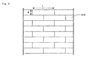
perforated body 10 in which the perforated plate 10A and the flow-adjuster 10B are integrated with each other can flow-adjust vacuum air within the fiber accumulating drum, and thus enables the absorbent body weight with a small deviation and fine fiber accumulation, whereby the profile of the entire cellulose wadding can be stabilized. This makes it possible to increase the rotational speed of a fiber accumulating drum and consequently possible to improve production efficiency. Provision of the flow-adjuster 10B leads to stabilization under constant vacuum pressure conditions, for example, at 4000 Pa, maximally in the range of from 3800 to 4200 Pa (can be suppressed to an inaccuracy of about 5% or less). In addition, because of the honeycomb structure of the flow-adjuster 10B, making this structure be integrated with the perforated plate 10A (e.g., by welding) increases rigidity, rarely distorts the perforated plate 10A and enables the accumulation of the entire cellulose wadding to be uniformed. - As a transverse cross sectional shape of the flow-adjuster 10B (layer structure), a form of the longitudinal stacking of bricks as shown in
FIG. 5 can be considered. In this case, the size of a measure of the flow-adjuster 10B illustrated inFIGS. 3 and5 may be 20 mm or less (excluding 0 mm) in the length (L) in the longitudinal direction, 20 mm or less (excluding 0 mm) in the width (W) and 20 mm or less (excluding 0 mm) in height (H) . The back side and external side of the flow-adjuster 10B in this case are indicated inFIG. 7 andFig. 8 , respectively. In addition, the perforated plate 10A on the external side is not illustrated. Another form may be a bellows shape as shown inFIG. 7 , or a lattice shape (not shown) . - Additionally, the shape of the sucking pore 10a, 10a, ..., of the perforated plate 10A, as sucking
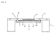
pores FIG. 9 , may be subjected to processing in which the pore size becomes small toward the inside of thefiber accumulating drum 1 and be formed in a cone shape from the external side toward the internal side. - Moreover, a
convex member 110X protruding in a direction away from the fiber accumulating drum as illustrated inFIG. 14 can be detachably provided in a portion of a concave portion (an absorbent body-forming concave portion) having the perforated plate 10A of being the surface of theperforated body 10 as a bottom portion to which a fluff pulp or a high water absorptive polymer is supplied. - A fiber accumulating apparatus according to the present invention includes a
fiber accumulating drum 1 having aperforated body 4 constituted by, for example as shown inFIG. 9 , a mesh, punching metal or the like having a large number of suckingpores fiber accumulating drum 1, and a suckingchamber 2 disposed in the internal side of thefiber accumulating drum 1. The inside of the suckingchamber 2 is maintained at a negative pressure by sucking means (not shown) to thereby accumulate an air-conveyed absorptive raw material S including a fluff pulp or a high water absorptive polymer on the surface of aperforated body 4. - The
perforated body 4, as illustrated inFIG. 10 , is attached to anauxiliary ring 13 throughbolts fiber accumulating drum 1 in the transverse direction, and a surface of theperforated body 4 as a bottom portion. On the basis of the fiber accumulating apparatus of the above construction, the fluff pulp and high water absorptive polymer are supplied to the inside of the concave portion having the surface of theperforated body 4 as a bottom portion and accumulated and formed in a predetermined shape within the concave portion on account of a negative pressure within the sucking chamber. - In addition, below the fiber accumulating drum, as shown in
FIG. 1 described above, aconveyer 55 with a sucking device is disposed that transfers and conveys an absorbent body adsorbed on and held by the fiber accumulating drum. Because of this, an absorbent body accumulated by the suckingchamber 2 is rotated to a peripheral direction while being adsorbed on and held by the outer periphery of thefiber accumulating drum 1, transferred onto the conveyer by the sucking device when reaching theconveyer 55 with a sucking device, and directly conveyed. - As illustrated in
FIG. 2 , theconventional mesh 32 has been generally processed by cylindrical punching, so that a large amount of loss of a raw material is caused due to its passage to the inside of the fiber accumulating drum, and the mesh needs to be frequently water washed due to clogging of high absorptive polymer. However, in the present invention, since themesh 4 has been generally processed by conic type etching an absorbent body raw material to be sucked can be prevented from passing into the inside to thereby reduce the loss of the raw material, without complete fitting of the absorbent body raw material in the sucking pores. On the other hand, when an absorbent body is transferred from thefiber accumulating drum 1 to theconveyer 55 with a sucking device as a next step, the absorbent body is transferred from the external side having a large pore size, so that the raw material is not clogged within the suckingpores perforated body 4 can be eliminated. - Specifically, a cone shape is suitably formed in such a manner that the pore size of the sucking
pore - On the other hand, the opening ratio of the perforated body such as the
conventional mesh 32 is low of less than 30%, and the number of pores per area is small, so that the vacuum air is liable to be an eddy flow and thus there is a problem in that fine, uniform fiber accumulation cannot be conducted. However, the opening ratio of the suckingpores - The above construction makes it possible to suppress clogging or the like of a fluff pulp or a high water absorptive polymer, of powder particles having different particle sizes and shapes. For this reason, uniform vacuum force can be applied, pulp break or unevenness during fiber accumulation is hardly generated, fine fiber accumulation is possible, the profile of the cellulose wadding can be stabilized, and the weight deviation can be reduced.
- The sucking pores 4A, 4A, ..., in the
perforated body 4 may be, as illustrated inFIG. 11 , arranged alternately or in a lattice as shown inFIG. 12 , or in a grid (not shown). In addition, although not shown, the pore shape may be replaced by a pyramidal or funnel shape, in place of a conic shape. -
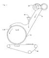
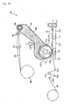
FIG. 13 is a schematic diagram of an apparatus for manufacturing an absorbent body including a fiber accumulating drum according to the present invention, andFIG. 14 is a plan view in the vicinity of its fiber accumulating drum. - An absorbent
body manufacturing apparatus 101 primarily includes a fluffer for finely crushing a pulp material (pulp raw fabric) 102 to be fed, a fluffpulp feeding casing 108 surrounding the fluffer, and afiber accumulating drum 110 placed in an opening downstream of the fluffpulp feeding casing 108. The fluffpulp feeding casing 108 constitutes the exterior cladding of a chamber C for conveying, on an air flow, the pulverized fluff pulp to the outer peripheral surface of the downstream fiber accumulating drum. In addition, the fluffpulp feeding casing 108 is provided with a functionalpowder feed opening 106 for feeding into the chamber a functional powder such as a polymer other than the fluff pulp, a deodorizing material, an antimicrobial material or an indicator. - The
fiber accumulating drum 110 has, at appropriate intervals in its outer peripheral surface, absorbent body-forming air-permeableconcave portions concave portion 110a is made a fine mesh or is provided with a large number of fine pores . Thefiber accumulating drum 110 is configured so as to accumulate the fluff pulp and the absorptive polymer in the absorbent body-formingconcave portions fiber accumulating drum 110 at a negative pressure by means of sucking means (not shown). - Here, in a fiber accumulating drum in the present invention, a
convex member 110X protruding in a direction away from the drum is detachably provided in portions of the absorbent body-formingconcave portions convex member 110X substantially has aconvex portion 110t for rendering an absorbent body to form a concave portion or a pore and an attachingportion 110h for detachably attachment to the outer peripheral surface of the drum. With theconvex member 110X attached, itsconvex portion 110t is protruded in a direction away from the drum in a portion of the absorbent body-formingconcave portion 110a, so that a concave portion or the like is formed in an absorbent body accumulated and formed in theconcave portion 110a for forming an absorbent body. A specific shape of theconvex portion 110t defines a shape of the concave portion or of the pore of an absorbent body. Hence, for example, if the shape of theconvex portion 110t is made to be substantially a dome shape, a cone-shaped concave portion or the like is formed in an absorbent body. On the other hand, when the top of theconcave portion 110t is a flat surface, an absorbent body having a concave portion with a bottom shape corresponding to the top face shape or having a pore with the corresponding shape is obtained. Although the specific position and the range of theconvex portion 110t, the total convex portion size and the convex portion height within the absorbent body-formingconcave portion 110a can be changed appropriately depending on a required absorbent body, for example, in the case of an absorbent body used for paper diaper applications, the position of the concave portion of the absorbent body is preferably disposed so as to be extendedly present toward the back side from the portion corresponding to a urination organ. For this reason, the convex portion is disposed so as to correspond to a position in which such a concave portion is formed, or to the like. In such applications, the area of the concave portion (flat view) is desirably made to be 1/6 or less of an absorption body area (flat view), so that the area covered with the convex member is made to be 1/6 or less of the area of the absorbent body-formingconcave portion 110a. Additionally, in such applications, the depth of the concave portion of an absorbent body is desirably 10 mm or less, and therefore the height of theconvex portion 110t of theconvex member 110X is made to be 10 mm or less. - The method for attaching the
convex member 110X to the absorbent body-forming concave portion (drum peripheral surface) 110a is not particularly limited. However, in the present embodiment, the attachingportion 110h formed with a plate spring having elasticity in the circumferential portion of theconvex member 110X is formed and also afitting groove 110m for fitting the portion in the drum outer peripheral surface is formed. It is configured that, with the attachingportion 110h bent, the brim of the attachingportion 110h is inserted into thefitting groove 110m of the drum outer peripheral surface and then the bending is stretched to thereby fit the convex member in a portion of the absorbent body- formingconcave portion - Here, in the present embodiment, with the
convex member 110X attached to the drum peripheral surface, the top of itsconvex portion 110t is located in a position protruded in a direction away from the drum outer peripheral surface. In other words, the height of theconvex portion 110t is set to be larger than the depth of the absorbent body-formingconcave portion 110a. This definitely prevents deposition of pulp and the like in the convex portion and forms a predetermined, good shaped concave portion or an absorbent body having a pore portion. - Furthermore, although a convex member can also be formed using a material having a fine air-permeable pore such as a mesh material or a punching metal, it is actually formed with a nonporous non-air-permeable material in the present embodiment. This ensures more definitely pulp or the like not to be accumulated in the convex member attaching portion, resulting in a good shaped concave portion or pore of an absorbent body as intended.
- Here, the above sucking means is configured so as to enable accumulation of the fluff pulp and polymer P on the absorbent body-forming
concave portion air supplying region 110B (symbol +) of supplying air to generate a positive pressure for the purpose of transferring the absorbent body S to aconveyer 115 with a sucking device as described below. It is configured so that thefluff pulp 107 and the polymer P accumulated on the absorbent body-formingconcave portion 110a of thefiber accumulating drum 110 are conveyed in a peripheral direction A (clockwise direction) while being adsorbed and held by suction and, when reaching theair supplying region 110B, transferred to the side of theconveyer 115 with the sucking device. - The
conveyer 115 with the sucking device receiving an absorbent body K from thefiber accumulating drum 110 is a conveyer that makes an air-permeable conveyer belt 118 hang over betweenrollers roller 119 in an appropriate place, with a structure in which the air-permeable conveyer belt 118 is put between thefiber accumulating drum 110 and a suckingdevice 120 placed in a downstream position thereof. To this theconveyer 115 with the sucking device, supplied iscrepe paper 121 to cover the undersurface side of the absorbent body K through guide rollers 122a to 122d and the absorbent body K is laminated on theabove crepe paper 121. - In this manner, the absorbent body K having a concave portion or a pore portion formed therein by means of a convex member is conveyed downstream together with the
crepe paper 121 and then passed through appropriate steps to be processed to an individual absorbent body unit. -
-
FIG. 1 is a schematic diagram of an apparatus for manufacturing an absorbent body. -
FIG. 2 is an enlarged sectional view of a fiber accumulating drum of a conventional example. -
FIG. 3 is a partial sectional view of a fiber accumulating drum according to the present invention for solving a first problem. -
FIG. 4 is a partial plan view of the fiber accumulating drum. -
FIG. 5 is a schematic diagram of a transverse cross section of a flow-adjuster. -
FIG. 6 is a schematic diagram of a transverse cross section of another flow-adjuster. -
FIG. 7 is a schematic diagram viewed from a back side of a transverse cross section of a flow-adjuster. -
FIG. 8 is a schematic diagram viewed from a front side of the transverse cross section of the flow-adjuster. -
FIG. 9 is a partial sectional view of a fiber accumulating drum according to the present invention for solving a second problem. -
FIG. 10 is a partial plan view of the fiber accumulating drum. -
FIG. 11 is a schematic diagram indicating an arrangement of sucking pores. -
FIG. 12 is a schematic diagram indicating another arrangement of sucking pores. -
FIG. 13 is a schematic diagram of an apparatus for manufacturing an absorbent body according to the present embodiment of solving a third problem. -
FIG. 14 is a plan view in the vicinity of the fiber accumulating drum. -
FIG. 15 is a schematic view of a conventional apparatus for manufacturing an absorbent body. -
- 1 fiber accumulating drum
- 2 sucking chamber
- 4 perforated body
- 4A sucking pore
- 10 perforated body
- 10A sucking plate
- 10B flow-adjuster
- 10a sucking pore
- 11 pattern ring
- 12 bolt
- S absorbent body raw material
- 101 absorbent body manufacturing apparatus
- 102 pulp material (pulp raw fabric)
- 103 pulp paper material
- 105 fluffer
- 106 functional powder feed opening
- 107 fluff pulp
- 108 fluff pulp feeding casing
- 110 fiber accumulating drum
- 110A suction region
- 110B air supplying region
- 110a absorbent body-forming concave portion
- 110X convex member
- 110t convex portion
- 110h attaching portion
- 110m convex member fitting groove
- 115 conveyer with sucking device
- 116, 117 roller
- 118 air-permeable conveyer belt
- 119 roller
- 120 sucking device
- 122a to 122d guide roller
- 121 crepe paper
Claims (18)
- A fiber accumulating apparatus comprising a fiber accumulating drum having a perforated body that accumulates an absorbent body raw material on its surface by suction from the internal side, wherein
the perforated body has a large number of sucking pores formed therein and comprises a perforated plate making up the surface and a flow-adjuster that is disposed on the internal side of the perforated plate and flow-adjusts an air flow, and the perforated plate and flow-adjuster are integrally constructed. - The fiber accumulating apparatus for an absorbent body according to claim 1, wherein the flow-adjuster is formed in a honeycomb structure.
- The fiber accumulating apparatus for an absorbent body according to claim 1 or 2, wherein the sucking pores of the perforated plate are formed in a cone shape toward the internal side from the external side.
- The fiber accumulating apparatus for an absorbent body according to any one of claims 1 to 3, wherein a convex member protruded in a direction away from the fiber accumulating drum is detachably provided in a portion of an absorbent body-forming concave portion in which the perforated plate is formed as a bottom portion.
- A method for manufacturing an absorbent body, wherein the fiber accumulating apparatus for an absorbent body of any one of claims 1 to 4 is used.
- An absorbent article having an absorbent body produced by the manufacturing method of claim 5.
- A fiber accumulating apparatus for an absorbent body, comprising:a fiber accumulating drum having a perforated body in which a large number of sucking pores are formed and an absorbent body raw material is accumulated on its surface by suction from the internal side, whereinthe sucking pore of the perforated body is formed in a cone shape from the external side toward the internal side.
- The fiber accumulating apparatus for an absorbent body according to claim 7, wherein the pore size of the sucking pore on the external side is 0.5 mm or less, and the pore size on the internal side is smaller than the pore size on the external side.
- The fiber accumulating apparatus for an absorbent body according to claim 7 or 8, wherein the opening ratio of the sucking pore on external side is 30% or more.
- The fiber accumulating apparatus for an absorbent body according to any one of claims 7 to 9, wherein the shape of the sucking pore is a conic, pyramidal or funnel shape.
- The fiber accumulating apparatus for an absorbent body according to any one of claims 7 to 10, wherein the sucking pores are arranged alternately, in a lattice or in a grid.
- A method for manufacturing an absorbent body, wherein the fiber accumulating apparatus for an absorbent body of any one of claims 7 to 11 is used.
- An absorbent article having an absorbent body produced by the manufacturing method of claim 12.
- A fiber accumulating drum for accumulating a fluff pulp conveyed on an air flow onto the surface of a rotating drum by suction from an internal side to form an absorbent body, wherein
a convex member protruded in a direction away from the drum is detachably provided in a portion of an absorbent body-forming air-permeable concave portion on which fluff pulp formed on the outer peripheral face of the drum is substantially accumulated. - The fiber accumulating drum according to claim 14, wherein the top of the convex member is located on the position protruded in a direction away from the outer peripheral surface of the drum.
- The fiber accumulating drum according to claim 14 or 15, wherein the convex member is non-air-permeable.
- A method for manufacturing an absorbent body, wherein the fiber accumulating drum of any one of claims 14 to 16 is used.
- An absorbent body that is produced by using the fiber accumulating drum of any one of claims 14 to 16.
Applications Claiming Priority (4)
| Application Number | Priority Date | Filing Date | Title |
|---|---|---|---|
| JP2005283490 | 2005-09-29 | ||
| JP2005283491 | 2005-09-29 | ||
| JP2005286564 | 2005-09-30 | ||
| PCT/JP2006/319429 WO2007037357A1 (en) | 2005-09-29 | 2006-09-29 | Fiber stacking and fiber stacking drum for absorbent, manufacturing method for absorbent using the same, and absorptive article having absorbent manufactured by the method |
Publications (3)
| Publication Number | Publication Date |
|---|---|
| EP1943991A1 true EP1943991A1 (en) | 2008-07-16 |
| EP1943991A4 EP1943991A4 (en) | 2012-04-11 |
| EP1943991B1 EP1943991B1 (en) | 2013-12-18 |
Family
ID=37899778
Family Applications (1)
| Application Number | Title | Priority Date | Filing Date |
|---|---|---|---|
| EP06810835.6A Active EP1943991B1 (en) | 2005-09-29 | 2006-09-29 | Fiber accumulating apparatus for absorbent body and method for manufacturing absorbent body |
Country Status (5)
| Country | Link |
|---|---|
| US (1) | US8020258B2 (en) |
| EP (1) | EP1943991B1 (en) |
| JP (3) | JP4499792B2 (en) |
| CN (1) | CN101277663B (en) |
| WO (1) | WO2007037357A1 (en) |
Cited By (4)
| Publication number | Priority date | Publication date | Assignee | Title |
|---|---|---|---|---|
| EP2612634A1 (en) * | 2010-08-31 | 2013-07-10 | Uni-Charm Corporation | Device for manufacturing absorber and method for manufacturing air permeable member |
| EP2859868A4 (en) * | 2012-06-11 | 2015-11-18 | Kao Corp | Fiber-stacking device |
| EP2581067B1 (en) | 2010-06-10 | 2017-04-26 | Kao Corporation | Process for production of absorber |
| EP3335682A4 (en) * | 2015-08-12 | 2019-04-03 | Sumitomo Seika Chemicals Co. Ltd. | Manufacturing method for absorbing body |
Families Citing this family (24)
| Publication number | Priority date | Publication date | Assignee | Title |
|---|---|---|---|---|
| DE4426753A1 (en) * | 1994-07-28 | 1996-02-01 | Bayer Ag | Means for controlling plant pests |
| WO2007037357A1 (en) * | 2005-09-29 | 2007-04-05 | Daio Paper Corporation | Fiber stacking and fiber stacking drum for absorbent, manufacturing method for absorbent using the same, and absorptive article having absorbent manufactured by the method |
| JP5210914B2 (en) * | 2009-02-05 | 2013-06-12 | ユニ・チャーム株式会社 | Absorber manufacturing apparatus and breathable member manufacturing method |
| TWI440043B (en) | 2009-09-08 | 2014-06-01 | Toshiba Kk | Semiconductor memory device |
| CN101797822A (en) * | 2010-03-29 | 2010-08-11 | 王韬 | Novel fiber reinforced cellular board and preparation method thereof |
| US8398915B2 (en) | 2010-08-12 | 2013-03-19 | Johnson & Johnson do Brasil Industria e Comercio Produtos Paral Saude Ltda. Rodovia | Method for making a fibrous article |
| US8480387B2 (en) | 2010-08-12 | 2013-07-09 | Johnson & Johnson Do Brasil Industria E Comercio Produtos Para Saude Ltda. | Apparatus for making a fibrous article having a three dimensional profile |
| US8388329B2 (en) | 2010-08-12 | 2013-03-05 | Johnson & Johnson Do Brasil Industria E Comercio Produtos Para Saude Ltda. Rodovia | Apparatus for making a fibrous article |
| US8394316B2 (en) | 2010-08-12 | 2013-03-12 | Johnson & Johnson Do Brasil Industria E Comercio Produtos Para Saude Ltda. Rodovia | Method for making a fibrous article |
| JP5765909B2 (en) * | 2010-09-30 | 2015-08-19 | ユニ・チャーム株式会社 | Rotating drum of fiber stacking equipment |
| US9464371B2 (en) | 2011-10-19 | 2016-10-11 | Kao Corporation | Fiber stacking device |
| JP5261557B2 (en) * | 2011-10-21 | 2013-08-14 | 花王株式会社 | Fiber stacking equipment |
| JP5836098B2 (en) * | 2011-12-08 | 2015-12-24 | 花王株式会社 | Absorber manufacturing equipment |
| CN105764459B (en) * | 2013-11-29 | 2019-11-19 | 花王株式会社 | The manufacturing device of absorber |
| JP6271313B2 (en) * | 2014-03-25 | 2018-01-31 | ユニ・チャーム株式会社 | Absorber manufacturing apparatus and manufacturing method |
| KR20170129868A (en) * | 2015-03-19 | 2017-11-27 | 쥐디엠 에스.피.에이. | A crusher for breaking up textile materials and a unit for forming an absorbent core in a machine for making absorbent sanitary articles |
| WO2016178144A1 (en) * | 2015-05-04 | 2016-11-10 | Gdm S.P.A. | Forming pocket and method for making a forming pocket |
| EP3097894B1 (en) * | 2015-05-28 | 2020-07-29 | The Procter and Gamble Company | Method of manufacturing unbonded, absorbent fibrous structures |
| KR102539701B1 (en) | 2015-08-12 | 2023-06-02 | 스미토모 세이카 가부시키가이샤 | Absorber manufacturing device |
| JP6333328B2 (en) * | 2016-09-12 | 2018-05-30 | 株式会社すぎはら | Dissimilar fiber supply device and dissimilar fiber supply method |
| EP3542766B1 (en) | 2016-12-27 | 2020-05-27 | Ontex BVBA | Absorbent core, articles comprising said core, and methods of making |
| CN108203880A (en) * | 2017-12-28 | 2018-06-26 | 耐途隆株式会社 | The functional materials adsorbent equipment of fiber |
| JP2023000517A (en) * | 2021-06-18 | 2023-01-04 | セイコーエプソン株式会社 | Web formation apparatus and molded body manufacturing apparatus |
| CN117137729A (en) * | 2023-10-18 | 2023-12-01 | 杭州川田卫生用品有限公司 | Processing device and processing method for convex cotton core of sanitary towel |
Citations (1)
| Publication number | Priority date | Publication date | Assignee | Title |
|---|---|---|---|---|
| GB1596718A (en) * | 1977-06-13 | 1981-08-26 | Johnson & Johnson | Non-woven fabric comprising buds and bundles connected by highly entangled fibous areas and methods of manufacturing the same |
Family Cites Families (24)
| Publication number | Priority date | Publication date | Assignee | Title |
|---|---|---|---|---|
| US3518726A (en) * | 1967-09-15 | 1970-07-07 | Kimberly Clark Co | Machine for making sanitary napkins |
| ZA75479B (en) | 1974-02-04 | 1976-08-25 | Colgate Palmolive Co | Disposable diaper with holes or wells |
| JPS53105573A (en) | 1977-02-25 | 1978-09-13 | Toa Nenryo Kogyo Kk | Production of laminate and device therefor |
| US4741941A (en) * | 1985-11-04 | 1988-05-03 | Kimberly-Clark Corporation | Nonwoven web with projections |
| US4761258A (en) * | 1985-12-10 | 1988-08-02 | Kimberly-Clark Corporation | Controlled formation of light and heavy fluff zones |
| US4666647A (en) * | 1985-12-10 | 1987-05-19 | Kimberly-Clark Corporation | Apparatus and process for forming a laid fibrous web |
| AU590032B2 (en) | 1985-12-10 | 1989-10-26 | Kimberly-Clark Worldwide, Inc. | Controlled formation of light and heavy fluff zones |
| US5004579A (en) * | 1989-05-26 | 1991-04-02 | Mcneil-Ppc-Inc. | Methods and apparatus for selective placement of fibrous material in formed fibrous articles |
| JP3153060B2 (en) * | 1993-11-29 | 2001-04-03 | 花王株式会社 | Fiber stacking method and fiber stacking device |
| JPH08229066A (en) | 1995-02-28 | 1996-09-10 | Mitsubishi Heavy Ind Ltd | Fiber stacking device |
| JP3248687B2 (en) | 1999-02-15 | 2002-01-21 | 花王株式会社 | Method and apparatus for manufacturing molded article |
| US6319455B1 (en) | 1999-08-13 | 2001-11-20 | First Quality Nonwovens, Inc. | Nonwoven fabric with high CD elongation and method of making same |
| US6630088B1 (en) * | 2000-10-23 | 2003-10-07 | Kimberly-Clark Worldwide, Inc. | Forming media with enhanced air flow properties |
| US6330735B1 (en) * | 2001-02-16 | 2001-12-18 | Kimberly-Clark Worldwide, Inc. | Apparatus and process for forming a laid fibrous web with enhanced basis weight capability |
| JP4104832B2 (en) | 2001-03-16 | 2008-06-18 | 大王製紙株式会社 | Absorber fiber stacking device |
| US20030021951A1 (en) * | 2001-07-20 | 2003-01-30 | The Procter & Gamble Company | High-elongation apertured nonwoven web and method for making |
| US6630096B2 (en) * | 2001-09-04 | 2003-10-07 | Kimberly-Clark Worldwide, Inc. | Multi-stage forming drum commutator |
| US6846448B2 (en) * | 2001-12-20 | 2005-01-25 | Kimberly-Clark Worldwide, Inc. | Method and apparatus for making on-line stabilized absorbent materials |
| US6989118B2 (en) * | 2002-01-15 | 2006-01-24 | Kimberly-Clark Worldwide, Inc. | Process for making a reinforced fibrous absorbent member |
| JP4070661B2 (en) | 2002-06-10 | 2008-04-02 | 花王株式会社 | Absorber manufacturing method |
| JP2004222774A (en) | 2003-01-20 | 2004-08-12 | Daio Paper Corp | Method of fiber-laminating absorber |
| JP4171335B2 (en) * | 2003-03-25 | 2008-10-22 | 株式会社リブドゥコーポレーション | Method and apparatus for manufacturing fiber laminate |
| JP4587909B2 (en) | 2005-08-24 | 2010-11-24 | 花王株式会社 | Rotating drum of fiber stacking equipment |
| WO2007037357A1 (en) * | 2005-09-29 | 2007-04-05 | Daio Paper Corporation | Fiber stacking and fiber stacking drum for absorbent, manufacturing method for absorbent using the same, and absorptive article having absorbent manufactured by the method |
-
2006
- 2006-09-29 WO PCT/JP2006/319429 patent/WO2007037357A1/en active Application Filing
- 2006-09-29 JP JP2007537693A patent/JP4499792B2/en not_active Expired - Fee Related
- 2006-09-29 EP EP06810835.6A patent/EP1943991B1/en active Active
- 2006-09-29 US US11/992,804 patent/US8020258B2/en not_active Expired - Fee Related
- 2006-09-29 CN CN2006800359893A patent/CN101277663B/en active Active
-
2009
- 2009-05-29 JP JP2009131143A patent/JP4451489B2/en active Active
- 2009-05-29 JP JP2009131144A patent/JP4451490B2/en active Active
Patent Citations (1)
| Publication number | Priority date | Publication date | Assignee | Title |
|---|---|---|---|---|
| GB1596718A (en) * | 1977-06-13 | 1981-08-26 | Johnson & Johnson | Non-woven fabric comprising buds and bundles connected by highly entangled fibous areas and methods of manufacturing the same |
Non-Patent Citations (1)
| Title |
|---|
| See also references of WO2007037357A1 * |
Cited By (7)
| Publication number | Priority date | Publication date | Assignee | Title |
|---|---|---|---|---|
| EP2581067B1 (en) | 2010-06-10 | 2017-04-26 | Kao Corporation | Process for production of absorber |
| EP2612634A1 (en) * | 2010-08-31 | 2013-07-10 | Uni-Charm Corporation | Device for manufacturing absorber and method for manufacturing air permeable member |
| EP2612634A4 (en) * | 2010-08-31 | 2014-07-23 | Uni Charm Corp | Device for manufacturing absorber and method for manufacturing air permeable member |
| US9486946B2 (en) | 2010-08-31 | 2016-11-08 | Uni-Charm Corporation | Apparatus for manufacturing absorbent body and method for manufacturing air-permeable member |
| EP2859868A4 (en) * | 2012-06-11 | 2015-11-18 | Kao Corp | Fiber-stacking device |
| EP3335682A4 (en) * | 2015-08-12 | 2019-04-03 | Sumitomo Seika Chemicals Co. Ltd. | Manufacturing method for absorbing body |
| US10945890B2 (en) | 2015-08-12 | 2021-03-16 | Sumitomo Seika Chemicals Co., Ltd. | Manufacturing method for absorbing body |
Also Published As
| Publication number | Publication date |
|---|---|
| EP1943991B1 (en) | 2013-12-18 |
| WO2007037357A1 (en) | 2007-04-05 |
| CN101277663B (en) | 2012-02-08 |
| EP1943991A4 (en) | 2012-04-11 |
| JP4451489B2 (en) | 2010-04-14 |
| US8020258B2 (en) | 2011-09-20 |
| JPWO2007037357A1 (en) | 2009-04-09 |
| JP2009240792A (en) | 2009-10-22 |
| US20090281511A1 (en) | 2009-11-12 |
| JP4451490B2 (en) | 2010-04-14 |
| CN101277663A (en) | 2008-10-01 |
| JP4499792B2 (en) | 2010-07-07 |
| JP2009183796A (en) | 2009-08-20 |
Similar Documents
| Publication | Publication Date | Title |
|---|---|---|
| US8020258B2 (en) | Fiber accumulating apparatus for absorbent body, fiber accumulating drum, and method for manufacturing absorbent body using the same, and absorbent article having absorbent body manufactured by the method | |
| CN102665626B (en) | Method and device for manufacturing absorption body | |
| TWI566760B (en) | Fiber stacking device | |
| JP4820333B2 (en) | Absorber manufacturing equipment | |
| US20130139960A1 (en) | Method for producing absorbent member | |
| CN103260565B (en) | Apparatus for producing absorbents | |
| JP5097423B2 (en) | Absorbent article and method for manufacturing absorbent article | |
| JP5953296B2 (en) | Absorber manufacturing equipment | |
| WO2015041077A1 (en) | Fibre-stacking device | |
| CN109640907A (en) | Method for manufacturing the device of absorber and for manufacturing absorber | |
| JP2002272782A (en) | Fiber accumulating device for absorbent article | |
| JP5197086B2 (en) | Absorber fiber stacking device and absorber | |
| JP4832908B2 (en) | Absorber fiber stacking apparatus, absorbent body manufacturing method using the same, and absorbent article having the absorbent body manufactured by the manufacturing method | |
| JPH11124761A (en) | Device for air laying fibrous material or particle material | |
| JP5457507B2 (en) | Fiber stacking equipment | |
| WO2018016490A1 (en) | Absorbent body manufacturing device and absorbent body manufacturing method | |
| CN104411277B (en) | Device for producing absorbent body | |
| TWI808099B (en) | Absorbent manufacturing method and absorbent manufacturing apparatus | |
| JP2013255554A (en) | Fiber-stacking device | |
| RU2407496C2 (en) | Device for accumulation of fibres for absorbent, fibre accumulation drum, and method of producing absorbent and its use, as well as absorbing article with said absorbent produced by said method | |
| JP2010509519A (en) | Equipment for manufacturing airlaid structures | |
| CN104470480B (en) | Absorber manufacture device | |
| WO2013058196A1 (en) | Fiber stacking device | |
| CN215131669U (en) | Absorber forming equipment of disposable sanitary product | |
| JP6513533B2 (en) | Stacking device |
Legal Events
| Date | Code | Title | Description |
|---|---|---|---|
| PUAI | Public reference made under article 153(3) epc to a published international application that has entered the european phase |
Free format text: ORIGINAL CODE: 0009012 |
|
| 17P | Request for examination filed |
Effective date: 20080429 |
|
| AK | Designated contracting states |
Kind code of ref document: A1 Designated state(s): AT BE BG CH CY CZ DE DK EE ES FI FR GB GR HU IE IS IT LI LT LU LV MC NL PL PT RO SE SI SK TR |
|
| A4 | Supplementary search report drawn up and despatched |
Effective date: 20120312 |
|
| RIC1 | Information provided on ipc code assigned before grant |
Ipc: A61F 13/531 20060101ALI20120306BHEP Ipc: A61F 13/49 20060101ALI20120306BHEP Ipc: A61F 13/472 20060101ALI20120306BHEP Ipc: A61F 13/15 20060101AFI20120306BHEP Ipc: D04H 1/70 20120101ALI20120306BHEP |
|
| DAX | Request for extension of the european patent (deleted) | ||
| 17Q | First examination report despatched |
Effective date: 20130131 |
|
| GRAP | Despatch of communication of intention to grant a patent |
Free format text: ORIGINAL CODE: EPIDOSNIGR1 |
|
| INTG | Intention to grant announced |
Effective date: 20130719 |
|
| INTG | Intention to grant announced |
Effective date: 20130724 |
|
| GRAS | Grant fee paid |
Free format text: ORIGINAL CODE: EPIDOSNIGR3 |
|
| GRAA | (expected) grant |
Free format text: ORIGINAL CODE: 0009210 |
|
| AK | Designated contracting states |
Kind code of ref document: B1 Designated state(s): AT BE BG CH CY CZ DE DK EE ES FI FR GB GR HU IE IS IT LI LT LU LV MC NL PL PT RO SE SI SK TR |
|
| REG | Reference to a national code |
Ref country code: GB Ref legal event code: FG4D |
|
| REG | Reference to a national code |
Ref country code: CH Ref legal event code: EP |
|
| REG | Reference to a national code |
Ref country code: AT Ref legal event code: REF Ref document number: 645231 Country of ref document: AT Kind code of ref document: T Effective date: 20140115 |
|
| REG | Reference to a national code |
Ref country code: IE Ref legal event code: FG4D |
|
| REG | Reference to a national code |
Ref country code: DE Ref legal event code: R096 Ref document number: 602006039709 Country of ref document: DE Effective date: 20140213 |
|
| REG | Reference to a national code |
Ref country code: NL Ref legal event code: VDEP Effective date: 20131218 |
|
| PG25 | Lapsed in a contracting state [announced via postgrant information from national office to epo] |
Ref country code: LT Free format text: LAPSE BECAUSE OF FAILURE TO SUBMIT A TRANSLATION OF THE DESCRIPTION OR TO PAY THE FEE WITHIN THE PRESCRIBED TIME-LIMIT Effective date: 20131218 Ref country code: SE Free format text: LAPSE BECAUSE OF FAILURE TO SUBMIT A TRANSLATION OF THE DESCRIPTION OR TO PAY THE FEE WITHIN THE PRESCRIBED TIME-LIMIT Effective date: 20131218 Ref country code: FI Free format text: LAPSE BECAUSE OF FAILURE TO SUBMIT A TRANSLATION OF THE DESCRIPTION OR TO PAY THE FEE WITHIN THE PRESCRIBED TIME-LIMIT Effective date: 20131218 |
|
| REG | Reference to a national code |
Ref country code: AT Ref legal event code: MK05 Ref document number: 645231 Country of ref document: AT Kind code of ref document: T Effective date: 20131218 |
|
| REG | Reference to a national code |
Ref country code: LT Ref legal event code: MG4D |
|
| PG25 | Lapsed in a contracting state [announced via postgrant information from national office to epo] |
Ref country code: LV Free format text: LAPSE BECAUSE OF FAILURE TO SUBMIT A TRANSLATION OF THE DESCRIPTION OR TO PAY THE FEE WITHIN THE PRESCRIBED TIME-LIMIT Effective date: 20131218 |
|
| PG25 | Lapsed in a contracting state [announced via postgrant information from national office to epo] |
Ref country code: IS Free format text: LAPSE BECAUSE OF FAILURE TO SUBMIT A TRANSLATION OF THE DESCRIPTION OR TO PAY THE FEE WITHIN THE PRESCRIBED TIME-LIMIT Effective date: 20140418 Ref country code: EE Free format text: LAPSE BECAUSE OF FAILURE TO SUBMIT A TRANSLATION OF THE DESCRIPTION OR TO PAY THE FEE WITHIN THE PRESCRIBED TIME-LIMIT Effective date: 20131218 Ref country code: BE Free format text: LAPSE BECAUSE OF FAILURE TO SUBMIT A TRANSLATION OF THE DESCRIPTION OR TO PAY THE FEE WITHIN THE PRESCRIBED TIME-LIMIT Effective date: 20131218 |
|
| PG25 | Lapsed in a contracting state [announced via postgrant information from national office to epo] |
Ref country code: CZ Free format text: LAPSE BECAUSE OF FAILURE TO SUBMIT A TRANSLATION OF THE DESCRIPTION OR TO PAY THE FEE WITHIN THE PRESCRIBED TIME-LIMIT Effective date: 20131218 Ref country code: PL Free format text: LAPSE BECAUSE OF FAILURE TO SUBMIT A TRANSLATION OF THE DESCRIPTION OR TO PAY THE FEE WITHIN THE PRESCRIBED TIME-LIMIT Effective date: 20131218 Ref country code: CY Free format text: LAPSE BECAUSE OF FAILURE TO SUBMIT A TRANSLATION OF THE DESCRIPTION OR TO PAY THE FEE WITHIN THE PRESCRIBED TIME-LIMIT Effective date: 20131218 Ref country code: PT Free format text: LAPSE BECAUSE OF FAILURE TO SUBMIT A TRANSLATION OF THE DESCRIPTION OR TO PAY THE FEE WITHIN THE PRESCRIBED TIME-LIMIT Effective date: 20140418 Ref country code: AT Free format text: LAPSE BECAUSE OF FAILURE TO SUBMIT A TRANSLATION OF THE DESCRIPTION OR TO PAY THE FEE WITHIN THE PRESCRIBED TIME-LIMIT Effective date: 20131218 Ref country code: ES Free format text: LAPSE BECAUSE OF FAILURE TO SUBMIT A TRANSLATION OF THE DESCRIPTION OR TO PAY THE FEE WITHIN THE PRESCRIBED TIME-LIMIT Effective date: 20131218 Ref country code: NL Free format text: LAPSE BECAUSE OF FAILURE TO SUBMIT A TRANSLATION OF THE DESCRIPTION OR TO PAY THE FEE WITHIN THE PRESCRIBED TIME-LIMIT Effective date: 20131218 Ref country code: RO Free format text: LAPSE BECAUSE OF FAILURE TO SUBMIT A TRANSLATION OF THE DESCRIPTION OR TO PAY THE FEE WITHIN THE PRESCRIBED TIME-LIMIT Effective date: 20131218 Ref country code: SK Free format text: LAPSE BECAUSE OF FAILURE TO SUBMIT A TRANSLATION OF THE DESCRIPTION OR TO PAY THE FEE WITHIN THE PRESCRIBED TIME-LIMIT Effective date: 20131218 |
|
| REG | Reference to a national code |
Ref country code: DE Ref legal event code: R026 Ref document number: 602006039709 Country of ref document: DE |
|
| PLBI | Opposition filed |
Free format text: ORIGINAL CODE: 0009260 |
|
| 26 | Opposition filed |
Opponent name: KIMBERLY-CLARK WORLDWIDE, INC. Effective date: 20140909 |
|
| PLAX | Notice of opposition and request to file observation + time limit sent |
Free format text: ORIGINAL CODE: EPIDOSNOBS2 |
|
| PG25 | Lapsed in a contracting state [announced via postgrant information from national office to epo] |
Ref country code: DK Free format text: LAPSE BECAUSE OF FAILURE TO SUBMIT A TRANSLATION OF THE DESCRIPTION OR TO PAY THE FEE WITHIN THE PRESCRIBED TIME-LIMIT Effective date: 20131218 |
|
| REG | Reference to a national code |
Ref country code: DE Ref legal event code: R026 Ref document number: 602006039709 Country of ref document: DE Effective date: 20140909 |
|
| PLBB | Reply of patent proprietor to notice(s) of opposition received |
Free format text: ORIGINAL CODE: EPIDOSNOBS3 |
|
| PG25 | Lapsed in a contracting state [announced via postgrant information from national office to epo] |
Ref country code: LU Free format text: LAPSE BECAUSE OF FAILURE TO SUBMIT A TRANSLATION OF THE DESCRIPTION OR TO PAY THE FEE WITHIN THE PRESCRIBED TIME-LIMIT Effective date: 20140929 Ref country code: MC Free format text: LAPSE BECAUSE OF FAILURE TO SUBMIT A TRANSLATION OF THE DESCRIPTION OR TO PAY THE FEE WITHIN THE PRESCRIBED TIME-LIMIT Effective date: 20131218 |
|
| REG | Reference to a national code |
Ref country code: CH Ref legal event code: PL |
|
| PG25 | Lapsed in a contracting state [announced via postgrant information from national office to epo] |
Ref country code: SI Free format text: LAPSE BECAUSE OF FAILURE TO SUBMIT A TRANSLATION OF THE DESCRIPTION OR TO PAY THE FEE WITHIN THE PRESCRIBED TIME-LIMIT Effective date: 20131218 |
|
| REG | Reference to a national code |
Ref country code: IE Ref legal event code: MM4A |
|
| PG25 | Lapsed in a contracting state [announced via postgrant information from national office to epo] |
Ref country code: CH Free format text: LAPSE BECAUSE OF NON-PAYMENT OF DUE FEES Effective date: 20140930 Ref country code: LI Free format text: LAPSE BECAUSE OF NON-PAYMENT OF DUE FEES Effective date: 20140930 |
|
| REG | Reference to a national code |
Ref country code: FR Ref legal event code: PLFP Year of fee payment: 10 |
|
| PG25 | Lapsed in a contracting state [announced via postgrant information from national office to epo] |
Ref country code: IE Free format text: LAPSE BECAUSE OF NON-PAYMENT OF DUE FEES Effective date: 20140929 |
|
| PLCK | Communication despatched that opposition was rejected |
Free format text: ORIGINAL CODE: EPIDOSNREJ1 |
|
| REG | Reference to a national code |
Ref country code: DE Ref legal event code: R100 Ref document number: 602006039709 Country of ref document: DE |
|
| PG25 | Lapsed in a contracting state [announced via postgrant information from national office to epo] |
Ref country code: BG Free format text: LAPSE BECAUSE OF FAILURE TO SUBMIT A TRANSLATION OF THE DESCRIPTION OR TO PAY THE FEE WITHIN THE PRESCRIBED TIME-LIMIT Effective date: 20131218 |
|
| PG25 | Lapsed in a contracting state [announced via postgrant information from national office to epo] |
Ref country code: IT Free format text: LAPSE BECAUSE OF FAILURE TO SUBMIT A TRANSLATION OF THE DESCRIPTION OR TO PAY THE FEE WITHIN THE PRESCRIBED TIME-LIMIT Effective date: 20131218 Ref country code: GR Free format text: LAPSE BECAUSE OF FAILURE TO SUBMIT A TRANSLATION OF THE DESCRIPTION OR TO PAY THE FEE WITHIN THE PRESCRIBED TIME-LIMIT Effective date: 20140319 |
|
| PG25 | Lapsed in a contracting state [announced via postgrant information from national office to epo] |
Ref country code: TR Free format text: LAPSE BECAUSE OF FAILURE TO SUBMIT A TRANSLATION OF THE DESCRIPTION OR TO PAY THE FEE WITHIN THE PRESCRIBED TIME-LIMIT Effective date: 20131218 Ref country code: HU Free format text: LAPSE BECAUSE OF FAILURE TO SUBMIT A TRANSLATION OF THE DESCRIPTION OR TO PAY THE FEE WITHIN THE PRESCRIBED TIME-LIMIT; INVALID AB INITIO Effective date: 20060929 |
|
| PLBN | Opposition rejected |
Free format text: ORIGINAL CODE: 0009273 |
|
| STAA | Information on the status of an ep patent application or granted ep patent |
Free format text: STATUS: OPPOSITION REJECTED |
|
| REG | Reference to a national code |
Ref country code: FR Ref legal event code: PLFP Year of fee payment: 11 |
|
| 27O | Opposition rejected |
Effective date: 20160502 |
|
| REG | Reference to a national code |
Ref country code: FR Ref legal event code: PLFP Year of fee payment: 12 |
|
| REG | Reference to a national code |
Ref country code: FR Ref legal event code: PLFP Year of fee payment: 13 |
|
| PGFP | Annual fee paid to national office [announced via postgrant information from national office to epo] |
Ref country code: GB Payment date: 20220811 Year of fee payment: 17 Ref country code: DE Payment date: 20220809 Year of fee payment: 17 |
|
| PGFP | Annual fee paid to national office [announced via postgrant information from national office to epo] |
Ref country code: FR Payment date: 20220808 Year of fee payment: 17 |