EP1943899B1 - Device for spraying rows of plants - Google Patents
Device for spraying rows of plants Download PDFInfo
- Publication number
- EP1943899B1 EP1943899B1 EP08000332A EP08000332A EP1943899B1 EP 1943899 B1 EP1943899 B1 EP 1943899B1 EP 08000332 A EP08000332 A EP 08000332A EP 08000332 A EP08000332 A EP 08000332A EP 1943899 B1 EP1943899 B1 EP 1943899B1
- Authority
- EP
- European Patent Office
- Prior art keywords
- air
- nozzles
- spray
- arrangement according
- frame
- Prior art date
- Legal status (The legal status is an assumption and is not a legal conclusion. Google has not performed a legal analysis and makes no representation as to the accuracy of the status listed.)
- Not-in-force
Links
Images


Classifications
-
- A—HUMAN NECESSITIES
- A01—AGRICULTURE; FORESTRY; ANIMAL HUSBANDRY; HUNTING; TRAPPING; FISHING
- A01M—CATCHING, TRAPPING OR SCARING OF ANIMALS; APPARATUS FOR THE DESTRUCTION OF NOXIOUS ANIMALS OR NOXIOUS PLANTS
- A01M7/00—Special adaptations or arrangements of liquid-spraying apparatus for purposes covered by this subclass
- A01M7/0003—Atomisers or mist blowers
- A01M7/0014—Field atomisers, e.g. orchard atomisers, self-propelled, drawn or tractor-mounted
Abstract
Description
Die Erfindung bezieht sich auf eine Vorrichtung zum Spritzen von Pflanzenzeilen, insbesondere Spalierkulturen, die entlang der jeweiligen Pflanzenzeile verfahrbar ist, mit einem Rahmen zur Halterung von mit einem Spritzmittel beaufschlagten Spritzmitteldüsen und mit mit mindestens einem Gebläse gekoppelten Luftdüsen, die den Spritzmitteldüsen derart zugeordnet sind, dass die aus den in zwei Reihen angeordneten Luftdüsen austretende Luft das aus den Spritzmitteldüsen austretende Spritzmittel in Richtung der Pflanzenzeile führt, wobei die aus den Luftdüsen der ersten Reihe austretende Luft das Spritzmittel beaufschlagt und die aus den Luftdüsen der zweiten Reihe austretende Luft einen Luftvorhang um das Luft-Spritzmittelgemisch bildet.The invention relates to a device for spraying plant rows, in particular trellis cultures, which can be moved along the respective plant row, with a frame for holding spray nozzles which are acted upon by a spray agent and with air nozzles coupled to at least one fan, which are assigned to the spray nozzle nozzles in such a way. in that the air emerging from the air nozzles arranged in two rows leads the spray medium emerging from the spray agent nozzles in the direction of the plant row, the air emerging from the air nozzles of the first row pressurizing the spray agent and the air emerging from the air nozzles of the second row enclosing an air curtain around the spray jet Air-spray mixture forms.
Eine derartige Vorrichtung ist aus der
Kultur- und Nutzpflanzen, wie Reben oder Obstbäume und dergleichen, werden häufig in langen und im Wesentlichen geradlinigen Reihen oder Zeilen angepflanzt, um eine maschinelle Bearbeitung, Düngung und/oder ein Ernten der Früchte der Pflanzen zu ermöglichen. Insbesondere im Weinbau werden an sich bekannte Überzeilengeräte eingesetzt, die im Wesentlichen einen portalartigen, nach unten offenen U-förmigen Rahmen umfassen, an dem verschiedene Einrichtungen zur Bearbeitung der Pflanzen angeordnet sind. Beispielsweise können Laubschneideeinrichtungen an dem Rahmen vorgesehen sein. Der Rahmen ist als so genanntes Anbaugerät an einem landwirtschaftlichen Nutzfahrzeug, wie einem Traktor, befestigt. Das Nutzfahrzeug fährt dann zwischen zwei benachbarten Zeilen, um beispielsweise Laub einer Reihe von Weinstöcken zu entfernen.Crops and crops, such as vines or fruit trees and the like, are often planted in long and substantially rectilinear rows or rows to allow for machining, fertilizing and / or harvesting the fruits of the plants. Especially in viticulture, known per se line devices are used, which essentially comprise a portal-like, downwardly open U-shaped frame on which various facilities for processing the plants are arranged. For example, foliage cutting devices may be provided on the frame. The frame is attached as a so-called attachment to an agricultural utility vehicle, such as a tractor. The commercial vehicle then travels between two adjacent ones Lines, for example, to remove leaves of a number of grapevines.
Weiterhin sind Spritzgeräte bekannt, mit denen Spritzmittel, wie Fungizide oder Herbizide, ausgebracht werden können, um die Reben eines Weinbergs unter anderem vor Schädlingen zu schützen. Dazu sind an einem Rahmen verteilt mehrere Spritzmitteldüsen angeordnet. Beim Entlangfahren an der Zeile wird das Spritzmittel aus einem Vorratstank auf dem Nutzfahrzeug mit einer Pumpe gefördert und durch die Spritzmitteldüsen ausgespritzt und dabei, gegebenenfalls unter Verwendung eines Gebläses, fein zerstäubt und verteilt.Furthermore sprayers are known with which sprays, such as fungicides or herbicides, can be applied to protect the vineyards of a vineyard, among other things, from pests. For this purpose, a plurality of spray nozzle nozzles are arranged distributed on a frame. When driving along the line, the spray is conveyed from a storage tank on the commercial vehicle with a pump and injected through the spray nozzles and thereby, optionally using a blower, finely atomized and distributed.
Ausgehend von diesem Stand der Technik ist der Fachmann vor die Aufgabe gestellt, eine Vorrichtung der eingangs genannten Art zu schaffen, bei der die Menge an benötigtem Spritzmittel reduziert ist.Based on this prior art, the skilled person has the task of creating a device of the type mentioned, in which the amount of spray required is reduced.
Erfindungsgemäß wird die Aufgabe dadurch gelöst, dass der Rahmen zum Bearbeiten der Pflanzenzeile U-förmig ausgebildet ist, wobei die vertikalen Abschnitte des Rahmens aus zwei beabstandet und parallel zueinander ausgerichteten sowie miteinander verbundenen Längsträgern gefertigt sind, von denen der, in Fahrtrichtung gesehen, vordere Längsträger die Spritzmitteldüsen sowie die Luftdüsen der ersten Reihe und der andere die Luftdüsen der zweiten Reihe trägt.According to the invention the object is achieved in that the frame is designed to edit the plant line U-shaped, wherein the vertical portions of the frame are made of two spaced and parallel aligned and interconnected longitudinal members, of which, seen in the direction of travel, front side members the spray nozzles and air nozzles of the first row and the other carries the air nozzles of the second row.
Eine derart ausgebildete Vorrichtung verfügt nicht nur über mehrere Spritzmitteldüsen zum Ausbringen eines in der Regel flüssigen Spritzmittels, sondern auch über zusätzliche Luftdüsen, die am Rahmen der Vorrichtung angeordnet sind. Die Lüftdüsen sind derart am Rahmen verteilt, dass die aus den Luftdüsen austretende Luft bzw. die Luftstrahlen quasi als Führung für das aus den Spritzmitteldüsen ausgetragene Spritzmittel dienen. Durch die zusätzlichen Luftstrahlen wird das Spritzmittel gezielt zu den zu behandelnden Pflanzen, insbesondere Weinreben, geleitet und insbesondere eine Laubwand der Pflanzenzeile durchbrochen, um das Spritzmittel gezielt in das Innere der Pflanzenzeile einzutragen. Dabei kann der Fachmann die Position, Anzahl und Ausrichtung der Spritz- und/oder Luftdüsen in Abhängigkeit von der Größe der zu behandelnden Pflanzen, der Fahrgeschwindigkeit der Vorrichtung bzw. des den Rahmen tragenden Nutzfahrzeuges sowie der Art des Spritzmittels wählen. Selbstverständlich kann die Vorrichtung für an sich beliebige Nutzpflanzen, wie Gemüse, Obst, Wein, Hopfen und dergleichen, eingesetzt werden.Such a device has not only several spray nozzles for discharging a generally liquid spray, but also on additional air nozzles, which are arranged on the frame of the device. The air vents are distributed on the frame so that the air emerging from the air nozzles or the air jets quasi as a guide for the discharged from the spray nozzles Serve spray. Due to the additional air jets, the spray is directed to the plants to be treated, especially vines, and in particular a foliage wall of the plant row broken to enter the spray targeted in the interior of the plant line. The person skilled in the art can choose the position, number and orientation of the spray and / or air nozzles depending on the size of the plants to be treated, the speed of travel of the device or of the commercial vehicle carrying the frame and the type of spray. Of course, the device for any crops, such as vegetables, fruits, wine, hops and the like, can be used.
Prinzipiell können die Luftdüsen und die Spritzmitteldüsen auch integriert ausgebildet sein, beispielsweise als kegeloder trichterartige Öffnung mit einem eingesetzten Spritzkegel, wodurch eine im Wesentlichen ringförmige Austrittsöffnung gebildet ist, durch die Luft und Spritzmittel gemeinsam ausströmen.In principle, the air nozzles and the spray nozzles can also be integrated, for example, as a cone or funnel-like opening with a spray cone inserted, whereby a substantially annular outlet opening is formed through the air and spray together flow out.
Mit den Luftdüsen wird eine Abdrift des ausgebrachten Spritzmittels erheblich verringert, was die benötigte Spritzmittelmenge pro Pflanze wesentlich reduziert und durch den Luftvorhang um die zu behandelnde Pflanzenzeile bzw. das verwirbelnde Luft-Spritzmittelgemisch nur wenig Spritzmittel in die Umgebung gelangt.With the air nozzles a drift of the applied spray is significantly reduced, which significantly reduces the amount of spray required per plant and passes through the air curtain around the plant line to be treated or the swirling air-spray mixture only little spray into the environment.
Durch die Ausgestaltung des Rahmens zum Bearbeiten der Pflanzenzeile werden die Pflanzen einer Zeile gleichzeitig von gegenüberliegenden Seiten besprüht, wodurch eine besonders gleichmäßige Behandlung aufgrund einer Verwirbelung in etwa in der Mitte der Zeile gewährleistet ist. Gleichzeitig wird durch die insbesondere oben und seitlich angeordneten Luftdüsen der zweiten Reihe, die selbstverständlich unabhängig von den Luftdüsen der ersten Reihe sowohl verstellbar als auch mit Luft, gegebenenfalls aus einem zweiten Gebläse, beaufschlagbar sind, eine allseitige Luftglocke um die Pflanzenzeile erzeugt.The design of the frame for processing the plant row, the plants of a row are sprayed simultaneously from opposite sides, whereby a particularly uniform treatment is ensured due to a turbulence approximately in the middle of the line. At the same time by the particular above and laterally arranged air nozzles of the second row, which of course independent from the air nozzles of the first row both adjustable and with air, optionally from a second blower, can be acted upon, produces an all-round air bell around the plant line.
Bevorzugt sind die Luftdüsen und/oder die Spritzmitteldüsen in einem seitlichen und/oder oberen Bereich des Rahmens angeordnet. Mit den seitlichen Luftdüsen wird zum einem eine Führung des von seitlichen Spritzdüsen ausgespritzten Spritzmittels und zum anderen eine seitliche Luft-Abschirmung des Luft-Spritzmittelgemisches erreicht. Besonders mit einer im oberen Bereich des U-förmigen Rahmens angeordneten Luftdüse kann ein abschirmender Luftstrom nach schräg unten erzeugt werden. Eine seitlich in einem unteren Bereich angeordnete Luftdüse zum Luftausstoß zur Führung des Spritzmittels wird vorzugsweise nach schräg oben ausgerichtet. Insgesamt werden die Luft- und Spritzdüsen, derart ausgerichtet, dass in etwa der Mitte der zu behandelnden Pflanzenzeile eine Verwirbelung des gegenläufig nach hinten ausgetragenen Spritzmittels zu dessen Verwirbelung erzielt und vorzugsweise mit Luft aus den Luftdüsen der zweiten Reihe einen Luftvorhang um die zu behandelnde Pflanze und den Spritznebel erzeugt wird, wodurch zum einen die insgesamt benötigte Spritzmittelmenge reduziert und die unmittelbare Umgebung vor einer Belastung durch das ausgetragene Spritzmittel geschützt ist.The air nozzles and / or the spray nozzle nozzles are preferably arranged in a lateral and / or upper region of the frame. With the side air nozzles for a leadership of sprayed from side spray nozzles spray and on the other hand, a lateral air-shielding of the air-spray mixture is achieved. Especially with a arranged in the upper region of the U-shaped frame air nozzle, a shielding air flow can be generated obliquely down. A laterally arranged in a lower region air nozzle for air ejection to guide the spray is preferably aligned obliquely above. Overall, the air and spray nozzles are aligned such that in about the middle of the plant row to be treated achieved a turbulence of the counter-discharged rear spray to the swirling and preferably with air from the air nozzles of the second row an air curtain around the plant to be treated and the spray mist is generated, whereby on the one hand reduces the total amount of spray agent required and the immediate environment is protected from exposure to the discharged spray.
Zur Anpassung der Vorrichtung an verschiedene zu bearbeitende Nutzpflanzen bzw. verschiedene Anbausituationen an unterschiedlichen Nutzfahrzeugen sind die Luftdüsen und/oder die Spritzmitteldüsen in ihrer jeweiligen Ausrichtung einstellbar. Dies kann entweder für jede Düse einzeln und manuell erfolgen oder es sind beispielsweise über eine Einstellvorrichtung alle Spritzmitteldüsen an einer Seite des Rahmens derart miteinander gekoppelt, dass sie miteinander verschwenkt werden. Dies kann auch ferngesteuert erfolgen. Somit kann ein Spritzmittel in Bewegungsrichtung der Vorrichtung nach vorne und/oder hinten sowie nach oben oder unten gerichtet ausgespritzt werden. Gleiches gilt für die aus den Luftdüsen austretende Luft bzw. Luftstrahlen.To adapt the device to different crops to be processed or different cultivation situations on different commercial vehicles, the air nozzles and / or the spray nozzles are adjustable in their respective orientation. This can be done either individually and manually for each nozzle or, for example, via an adjustment all spray nozzles on one side of the frame coupled together so that they are pivoted together. This can also be done remotely. Thus, a spray in the direction of movement of the device can be ejected directed forward and / or backward and up or down. The same applies to the air or air jets emerging from the air nozzles.
Zur weiteren Anpassung sind die Luftdüsen und/oder die Spritzmitteldüsen in ihrer Position relativ zum Rahmen veränderbar. Beispielsweise kann eine seitlich Spritzmitteldüse in ihrer Höhe zum Rahmen nach oben oder unten verschoben werden. Besonders bei dieser Ausgestaltung bietet es sich an, dass die Luftdüsen und die Spritzmitteldüsen jeweils über Schläuche mit einem zentralen Gebläse bzw. einem Spritzmitteltank in Verbindung stehen, um beliebige Positionen relativ zum Rahmen einnehmen zu können.For further adaptation, the air nozzles and / or the spray nozzle nozzles are variable in their position relative to the frame. For example, a side spray nozzle can be moved in height to the frame up or down. Especially in this embodiment, it makes sense that the air nozzles and the spray nozzles are in each case via hoses with a central blower or a spray agent tank in connection to take any position relative to the frame can.
Um beim gezielten Einbringen des Spritzmittels in die zu behandelnde Pflanze bzw. Pflanzenzeile einen Fahrtwind auszunutzen, sind vorzugsweise die Spritzmitteldüsen und die Luftdüsen der ersten Reihe, in Fahrtrichtung gesehen, vor den Luftdüsen der zweiten Reihe angeordnet.In order to take advantage of the airflow during the targeted introduction of the spray into the plant or plant row to be treated, the spray nozzle nozzles and the air nozzles of the first row, as seen in the direction of travel, are preferably arranged in front of the air nozzles of the second row.
In Ausgestaltung sind die Spritzmitteldüsen über Spritzmittelschläuche mit einer zentralen, an einem Spritzmitteltank angeschlossenen Pumpe und die Luftdüsen über Druckluftschläuche mit dem Gebläse verbunden.In an embodiment, the spray nozzles are connected via spray agent hoses with a central, connected to a spray tank pump and the air nozzles via compressed air hoses with the blower.
Zur vereinfachten Einstellung der Sprührichtung sind vorzugsweise die vertikalen Abschnitte des Rahmens verschwenkbar an einer die Pflanzenzeile übergreifenden Horizontalhalterung befestigt.For simplified adjustment of the spray direction are preferably the vertical sections of the frame are pivotally attached to a horizontal bracket over the plant line.
Zweckmäßigerweise sind die Fördermengen der durch die Luftdüsen geförderten Luft variabel einstellbar, um bei geringem Spritzmitteleinsatz auch nur eine leichte Unterstützung durch zusätzliche Luftstrahlen zu ermöglichen oder bei starkem Spritzmitteleinsatz die volle Kapazität auszuschöpfen oder eine anforderungsgerechte Luftglocke einzustellen. Dies kann beispielsweise durch variable Spaltöffnungen oder in sonstiger dem Fachmann bekannter Weise, auch z. B. durch die Anordnung mehrerer Gebläse, erfolgen.Conveniently, the flow rates of the air supplied by the air nozzles are variably adjustable to allow for low use of sprayer even only a slight support by additional air jets or full use of strong spray agent use the full capacity or adjust a requirement-appropriate air bell. This can be done for example by variable stomata or in any other known to the expert, including, for. B. by the arrangement of several fans.
Zur Anpassung an verschiedene Arten bzw. Größen von Nutzpflanzen ist der Rahmen in seiner Breite und/oder Höhe veränderbar. Dies kann beispielsweise bei Vierkant- oder Rundrohren, die den Rahmen bilden, durch das Ineinanderschieben bzw. Auseinanderziehen mehrerer Rohrsegmente erfolgen oder über sonstige teleskopierbare Einrichtungen. Die Anpassung der Dimensionierung des Rahmens kann entweder manuell erfolgen oder elektrisch, beispielsweise durch einen elektromotorischen Antrieb einer Teleskopiereinrichtung, und/oder hydraulisch. Teile des Rahmens können auch mit einer Spindel teleskopiert werden.To adapt to different species or sizes of crops, the frame in its width and / or height is variable. This can be done for example by square or round tubes that form the frame, by the telescoping or pulling apart several pipe segments or other telescoping devices. The adaptation of the dimensioning of the frame can either be done manually or electrically, for example by an electric motor drive a telescoping device, and / or hydraulically. Parts of the frame can also be telescoped with a spindle.
Vorzugsweise ist der Rahmen derart ausgelegt, dass er an einen Geräteträger eines landwirtschaftlichen Nutzfahrzeugs montiert werden kann. Gegebenenfalls kann das Gebläse der Vorrichtung auch über die Zapfwelle beispielsweise eines Traktors betrieben werden. Dabei kann die Vorrichtung bzw. der Rahmen an dem Nutzfahrzeug, in Fahrtrichtung gesehen, vorne oder hinten, jeweils links oder rechts am Nutzfahrzeug angeordnet werden, um eine Zeile von Nutzpflanzen zu bearbeiten. Selbstverständlich wird je nach Montageort die Ausrichtung und Positionierung der Spritzmitteldüsen sowie der Luftdüsen entsprechend eingestellt, um optimale Ergebnisse zu erzielen. Der Rahmen kann auch Bestandteil eines Laubschneiders sein, an dem die Spritzmittel- und Luftdüsen befestigt werden. Solche als Überzeilengeräte ausgebildeten Laubschneider werden im Weinbau häufig eingesetzt und sind daher bei vielen Winzern vorhanden. Sonach ist es möglich, in einem Arbeitsgang sowohl überschüssiges Laub abzuschneiden als auch ein notwendiges Spritzmittel auszubringen. Um die Montage zu vereinfachen, können die Spritzmittel- und Luftdüsen an einem Gestänge gehaltert sein, das an dem Rahmen des Laubschneiders zu befestigen ist.Preferably, the frame is designed such that it can be mounted on a device carrier of an agricultural utility vehicle. Optionally, the fan of the device can also be operated via the PTO, for example, a tractor. In this case, the device or the frame on the utility vehicle, seen in the direction of travel, front or rear, respectively left or right to be arranged on the commercial vehicle to edit a row of crops. Of course, depending on the installation site Adjustment and positioning of the spray nozzles and the air nozzles are adjusted accordingly for optimum results. The frame may also be part of a foliage cutter to which the spray and air nozzles are attached. Such trained as Überzeilengeräte foliage cutter are often used in viticulture and are therefore present in many winemakers. Sonach it is possible to cut off in one operation both excess leaves and deploy a necessary spray. To facilitate assembly, the spray and air nozzles may be supported on a linkage which is to be attached to the frame of the foliage cutter.
Nach einer Weiterbildung ist der Rahmen an einem auf einem Fahrgestell, insbesondere mit einem Antriebsmotor, angeordneten Halter befestigt. Das ein- oder mehrachsige Fahrgestell ist beispielsweise vor oder hinter einem Nutzfahrzeug anzuordnen und die Radachsen können starr oder pendelnd gelagert sein. Gegebenenfalls können auch mehrere Fahrgestelle aneinander gekuppelt werden.According to a development of the frame is attached to a on a chassis, in particular with a drive motor, arranged holder. The single or multi-axle chassis is to be arranged, for example, in front of or behind a commercial vehicle and the wheel axles can be mounted rigidly or oscillatingly. Optionally, several chassis can be coupled together.
Zur Erzielung einer relativ hohen Laufruhe ist bevorzugt mindestens eine Radachse des Fahrgestells in ihrer Breite einstellbar und/oder hydraulisch oder mechanisch angetrieben. Die Einstellung bzw. Verstellung der Radachse kann sowohl manuell als auch hydraulisch erfolgen. Beispielsweise kann eine relativ geringe Achsbreite im Weinberg oder auf der Straße und eine große Achsbreite auf einem Acker verwendet werden. Der Achsantrieb wirkt sich insbesondere in Steillagen vorteilhaft aus. Demnach ist das Fahrgestell bei einem standardisierten Aufbau vielseitig verwendbar.To achieve a relatively high degree of smoothness at least one wheel axle of the chassis is preferably adjustable in width and / or driven hydraulically or mechanically. The adjustment or adjustment of the wheel axle can be done both manually and hydraulically. For example, a relatively small axle width in the vineyard or on the road and a large axle width can be used in one field. The final drive has an advantageous effect especially in steep slopes. Accordingly, the chassis is versatile in a standardized structure.
In weiterer Ausgestaltung umfasst der Halter vertikale Stützen, an denen oberseitig zwei Kragarme befestigt sind, um zwei Rahmen zur gleichzeitigen Bearbeitung von zwei Zeilen zu haltern. Die Kragarme dienen zur Befestigung von landwirtschaftlichen Geräten, wie beispielsweise einem Rahmen der Vorrichtung. Zweckmäßigerweise sind die Kragarme in ihrer Ausladung einzeln oder gemeinsam arretierbar verstellbar. Um eine möglicht große Ausladung bei einer verhältnismäßig stabilen Lagerung zu erzielen, erstrecken sich vorzugsweise die Kragarme gegenläufig zu Führungsarmen, die in einer gemeinsamen horizontalen Ebene hintereinander in Führungsrohren verschiebbar gelagert sind. Selbstverständlich können zwischen den Führungsrohren und den Führungsarmen Lagerbauteile und/oder Verstell- bzw. Arretiereinrichtungen vorgesehen sein. Zweckmäßigerweise sind die gegenüberliegenden Kragarme rechtwinklig an jeweils einem Distanzarm befestigt, der rechtwinklig horizontal sowie stirnseitig von dem entsprechenden Führungsarm abgeht, wobei die Kragarme in einer gemeinsamen horizontalen Ebene verlaufen. Damit steht bei einer hintereinander liegenden Anordnung der Führungsarme eine Befestigungsebene der Kragarme zur Halterung unterschiedlicher Vorrichtungen zur Verfügung. Um eine sichere Befestigung von Anbauteilen zu ermöglichen, sind bevorzugt gegenüberliegende Kragarme in zwei parallel und beabstandet zueinander verlaufenden Ebenen übereinander angeordnet. Demnach stehen jeweils zwei übereinander angeordnete Kragarme pro Seite zur Verfügung.In a further embodiment, the holder comprises vertical supports, on which two cantilevers are fastened on top, to two frames for the simultaneous processing of two lines to hold. The cantilevers are used for attachment of agricultural equipment, such as a frame of the device. Conveniently, the cantilevers are adjustable in their projection individually or jointly lockable. In order to achieve a large projection possible with a relatively stable storage, preferably the cantilevers extend in opposite directions to guide arms, which are mounted in a common horizontal plane one behind the other in guide tubes slidably. Of course, bearing components and / or adjusting or locking devices can be provided between the guide tubes and the guide arms. Conveniently, the opposite cantilevers are attached at right angles to a respective spacer arm, the right angle horizontally and frontally from the corresponding guide arm, the cantilevers extending in a common horizontal plane. This is in a successive arrangement of the guide arms is a mounting plane of the cantilevers for holding different devices available. In order to enable a secure attachment of attachments, preferably opposite cantilevers are arranged one above the other in two parallel and spaced-apart planes. Accordingly, there are two superposed cantilever arms per side.
Vorzugsweise ist der Halter bzw. sind seine vertikalen Stützen gemeinsam oder separat in der Höhe verstellbar. Dies ist insbesondere bei der Bearbeitung von terassenförmig oder an Hängen angelegten Pflanzenzeilen von Vorteil.Preferably, the holder or its vertical supports are adjustable together or separately in height. This is particularly advantageous when working on terraced or plant lines planted on slopes.
Es versteht sich, dass die vorstehend genannten und nachstehend noch zu erläuternden Merkmale nicht nur in der jeweils angegebenen Kombination, sondern auch in anderen Kombinationen verwendbar sind. Der Rahmen der Erfindung ist nur durch die Ansprüche definiert.It goes without saying that the features mentioned above and those yet to be explained below can be used not only in the respectively specified combination but also in other combinations. The scope of the invention is defined only by the claims.
Die Erfindung wird im Folgenden anhand eines Ausführungsbeispieles mit Bezugnahme auf die Zeichnungen näher erläutert. Es zeigt:
- Fig.1
- eine Teil-Darstellung einer Seitenansicht einer erfindungsgemäßen Vorrichtung,
- Fig.2
- eine Vorderansicht der Vorrichtung nach
Fig. 1 , - Fig.3
- eine schematische Darstellung einer Verwendung der Vorrichtung nach
Fig. 1 , - Fig.4
- eine Darstellung eines Fahrgestells für die Vorrichtung nach
Fig. 1 , - Fig.5
- eine Seitenansicht des Fahrgestells nach
Fig. 4 und - Fig.6
- eine schematische Darstellung einer Draufsicht auf die vergrößerte Einzelheit VI nach
Fig. 5 .
- Fig.1
- a partial representation of a side view of a device according to the invention,
- Fig.2
- a front view of the device according to
Fig. 1 . - Figure 3
- a schematic representation of a use of the device according to
Fig. 1 . - Figure 4
- a representation of a chassis for the device according to
Fig. 1 . - Figure 5
- a side view of the chassis after
Fig. 4 and - Figure 6
- a schematic representation of a plan view of the enlarged detail VI after
Fig. 5 ,
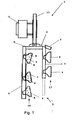
Die Vorrichtung 1 umfasst im Wesentlichen einen portalartigen, U-förmigen Rahmen 2, an dem ein Gebläse 3 zum Ansaugen und Fördern von Luft vorgesehen ist, das über nicht dargestellte Schläuche mit Luftdüsen 4 in Verbindung steht. Der Rahmen 2 ist an jedem seiner vertikalen Abschnitte 5 aus parallel zueinander ausgerichteten sowie miteinander verbundenen Längsträgern 6, 7 gefertigt, wobei der eine Längsträger 6 teleskopierbar ausgebildet ist und eine erste Reihe 16 Luftdüsen 4 sowie Spritzmitteldüsen 8 trägt und der andere Längsträger 7 mit einer zweiten Reihe 17 Luftdüsen bestückt ist. Hierbei sind die Spritzmitteldüsen 8 und die Luftdüsen 4 der ersten Reihe 16, in Fahrtrichtung der Vorrichtung gesehen, vor den Luftdüsen 4 der zweiten Reihe 16 angeordnet. Zur gezielten Einbringung eines Spritzmittelnebels in zu behandelnde Pflanzenzeile sowie zur Erzeugung einer den Spritzmittelnebel umgebenden und richtenden Luftglocke sind sowohl die Spritzmitteldüsen 8 als auch die Luftdüsen 4 der ersten Reihe 16 und der zweiten Reihe 17 derart verstellbar gelagert, dass zum einen Spritzmittel-18 und Luftstrahlen 19 ins Zentrum der Pflanzenzeile 20 gerichtet sind und weitere Luftstrahlen 21 die den Spritzmittelnebel abschirmende Luftglocke bilden. Die beiden Längsträger 6, 7 sind an ihren oberen Ende über ein Verbindungsprofil 9 miteinander gekoppelt, wobei das Verbindungsprofil 9 gelenkig mit einer teleskopierbaren Horizontalhalterung 10 in Verbindung steht, die in ihrer Mitte eine Luftdüse 4 trägt.The
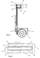
Der Rahmen 2 lässt sich an einem landwirtschaftlichen Nutzfahrzeug oder an einem an ein Nutzfahrzeug anzukuppelnden, Anhängevorrichtungen 25 aufweisenden Fahrgestell 11 angeordneten Halter 12 befestigen. Das Fahrgestell 11 weist eine in ihrer Breite einstellbare Radachse 13 auf, um eine relativ hohe Laufruhe zu erzielen. Im Weiteren umfasst der Halter 12 vertikale Stützen 14, die hydraulisch in ihrer Länge entweder gemeinsam oder einzeln verstellbar sind und an ihren oberen Enden in ihrer Ausladung verstellbare Kragarme 15 tragen. An dem Halter 12 lassen sich die Rahmen 2 von zwei Vorrichtungen 1 befestigen, um gleichzeitig zwei Zeilen von Pflanzen zu bearbeiten.The
Die Kragarme 15 sind endseitig an Distanzarmen 21 befestigt, die an in Führungsrohren 22 verschiebbar gelagerten Führungsarmen 23 festgelegt sind. Die Kragarme 15 verlaufen in einer zu den Führungsarmen 23 entgegengesetzten Richtung und bilden gemeinsam mit den Distanzarmen 21 im Wesentlichen eine C-Form. Pro Seite sind zwei übereinander angeordnete Kragarme 15 vorgesehen, die über Distanzrohre 24 miteinander verbunden sind. An den Führungsrohren 22 sind die vertikalen Stützen 14 des Halters 12 angeordnet.The
Prinzipiell ist es möglich, die Spritzmitteldüsen 8 und die Luftdüsen 4 als gemeinsames Bauteil auszuführen, beispielsweise als ein sich trichterförmig erweiterndes Auslassventil, in das wiederum ein Spritzkegel eingesetzt ist, so dass durch einen im Wesentlichen ringförmigen Spalt ein Luft/Spritzmittelgemisch austritt.In principle, it is possible to carry out the
Claims (20)
- Arrangement for spraying lines of plants (20), in particular trellis crops, which can be moved along the respective line of plants, having a frame (2) for holding spray nozzles (8) which are charged with a spray and having air nozzles (4) which are coupled to at least one blower (3) and which are assigned to the spray nozzles (8) such that the air that emerges from the air nozzles (4), which are arranged in two rows, guides the spray that emerges from the spray nozzles (8) in the direction of the line of plants, wherein the air that emerges from the air nozzles (4) of the first row (16) acts on the spray and the air that emerges from the air nozzles (4) of the second row (17) forms a curtain of air around the air-spray mixture, characterized in that the frame (2) is formed in a U-shaped manner in order to treat the lines of plants (20), with the vertical portions (5) of the frame (2) being produced from two longitudinal carriers (6, 7) which are oriented in a manner spaced apart from and parallel to one another and are connected together and of which the front longitudinal carrier (7), as seen in the direction of travel, carries the spray nozzles (8) and the air nozzles (4) of the first row (16) and the other carries the air nozzles (4) of the second row (17).
- Arrangement according to Claim 1, characterized in that the air nozzles (4) and/or the spray nozzles (8) are arranged in a lateral and/or upper region of the frame (2).
- Arrangement according to either of Claims 1 and 2, characterized in that the respective orientation of the air nozzles (4) and/or the spray nozzles (8) can be set.
- Arrangement according to one of Claims 1 to 3, characterized in that the position of the air nozzles (4) and/or the spray nozzles (8) in relation to the frame (2) can be changed.
- Arrangement according to one of Claims 1 to 4, characterized in that the spray nozzles (8) and the air nozzles (4) of the first row (16), as seen in the direction of travel, are arranged in front of the air nozzles (4) of the second row (17).
- Arrangement according to one of Claims 1 to 5, characterized in that the spray nozzles (8) are connected via a spray hose to a central pump which is connected to a spray tank, and the air nozzles (4) are connected to the blower (3) via compressed air hoses.
- Arrangement according to Claim 1, characterized in that the vertical portions (5) of the frame (2) are fastened in a pivotable manner to a horizontal holder (10) which reaches over the line of plants (20).
- Arrangement according to one of Claims 1 to 7, characterized in that the quantity of air conveyed can be changed.
- Arrangement according to Claim 1, characterized in that the width and/or height of the frame (2) can be changed.
- Arrangement according to one of Claims 1 to 9, characterized in that the frame (2) can be mounted on a tool carrier of an agricultural utility vehicle.
- Arrangement according to one of Claims 1 to 9, characterized in that the frame (2) is a constituent part of a foliage cutter.
- Arrangement according to one of Claims 1 to 9, characterized in that the frame (2) is fastened to a holder (12) that is arranged on an, in particular single-axle, chassis (11).
- Arrangement according to Claim 12, characterized in that the chassis (11) is intended to be arranged in front of or behind a utility vehicle.
- Arrangement according to Claim 12 or 13, characterized in that the width of at least one axle (13) of the chassis (11) can be set and/or said axle (13) can be hydraulically or mechanically driven.
- Arrangement according to Claim 12, characterized in that the holder (12) comprises vertical supports (14) on the top side of which there are fastened two cantilevers (15) in order to hold two frames (2) for the simultaneous treatment of two lines of plants (20).
- Arrangement according to Claim 15, characterized in that the extension of the cantilevers (15) can be individually or jointly adjusted in a lockable manner.
- Arrangement according to Claim 15 or 16, characterized in that the cantilevers (15) extend in the opposite direction to guide arms (23) which are mounted in a movable manner in a common horizontal plane one after another in guide tubes (22).
- Arrangement according to one of Claims 15 to 17, characterized in that the opposite cantilevers (15) are fastened at right angles on in each case one spacer arm (21) which protrudes horizontally at right angles and also from the end side of the corresponding guide arm (23), with the cantilevers (15) extending in a common horizontal plane.
- Arrangement according to one of Claims 15 to 18, characterized in that the opposite cantilevers (15) are arranged one above the other in two planes that extend in a manner parallel to and spaced apart from one another.
- Arrangement according to Claim 14, characterized in that the height of the holder (12) or its vertical supports (14) can be adjusted jointly or separately.
Applications Claiming Priority (1)
| Application Number | Priority Date | Filing Date | Title |
|---|---|---|---|
| DE102007002046A DE102007002046B4 (en) | 2007-01-13 | 2007-01-13 | Device for spraying plant lines |
Publications (2)
| Publication Number | Publication Date |
|---|---|
| EP1943899A1 EP1943899A1 (en) | 2008-07-16 |
| EP1943899B1 true EP1943899B1 (en) | 2011-11-09 |
Family
ID=39361771
Family Applications (1)
| Application Number | Title | Priority Date | Filing Date |
|---|---|---|---|
| EP08000332A Not-in-force EP1943899B1 (en) | 2007-01-13 | 2008-01-10 | Device for spraying rows of plants |
Country Status (3)
| Country | Link |
|---|---|
| EP (1) | EP1943899B1 (en) |
| AT (1) | ATE532408T1 (en) |
| DE (1) | DE102007002046B4 (en) |
Cited By (1)
| Publication number | Priority date | Publication date | Assignee | Title |
|---|---|---|---|---|
| EP4098118A1 (en) * | 2021-05-31 | 2022-12-07 | Yanmar Holdings Co., Ltd. | Spraying machine |
Families Citing this family (4)
| Publication number | Priority date | Publication date | Assignee | Title |
|---|---|---|---|---|
| DE102010012053B4 (en) | 2010-03-19 | 2014-04-30 | Aloys Müller | Device for spraying plants |
| WO2013090641A1 (en) * | 2011-12-13 | 2013-06-20 | Genz Corp. | Recapture sprayer |
| ITVR20120250A1 (en) * | 2012-12-21 | 2014-06-22 | Scolari Attrezzature Agricole Di Sc Olari Stefano | AGRICULTURAL ATOMIZER WITH CONTROLLED DISPERSION FOR PESTICIDE TREATMENTS |
| US11147258B2 (en) | 2018-02-12 | 2021-10-19 | Capstan Ag Systems, Inc. | Systems and methods for spraying an agricultural fluid on foliage |
Family Cites Families (8)
| Publication number | Priority date | Publication date | Assignee | Title |
|---|---|---|---|---|
| DE2926922C2 (en) * | 1979-06-30 | 1982-04-08 | Rainer von Dipl.-Ing. 1000 Berlin Oheimb | Sprayer for line-dependent application of pesticides |
| BR8205194A (en) * | 1982-09-02 | 1984-02-28 | Mogiana Insumos Ltda | IMPROVEMENT IN MOBILE SATURATION CAMERA FOR THE APPLICATION OF AGRICULTURAL DEFENSIVES |
| DE3803145A1 (en) * | 1988-02-03 | 1989-08-17 | Henry Ehrenberg | PLANT PROTECTION DISCHARGE DEVICE |
| DE3901463A1 (en) * | 1989-01-19 | 1990-07-26 | John & Co | Appliance for the spraying of planted rows of fruit |
| NZ249438A (en) * | 1992-03-05 | 1997-03-24 | Donald Charles Barlow | Spraying apparatus; frame supports a tank containing liquid to be sprayed, a tower assembly having a number of spray outlet nozzles therealong |
| US5269461A (en) * | 1992-03-13 | 1993-12-14 | Davis James F | Aerosol nozzle system |
| NL9201297A (en) * | 1992-07-20 | 1994-02-16 | Munckhof J M Maschf | Tunnel-shaped spraying vehicle. |
| FR2868341B1 (en) * | 2004-04-06 | 2008-01-04 | Exel Ind | SPRAYING METHOD, SPOUT FOR CARRYING OUT SAID METHOD, AND APPARATUS EQUIPPED WITH SUCH A SPOUT |
-
2007
- 2007-01-13 DE DE102007002046A patent/DE102007002046B4/en not_active Expired - Fee Related
-
2008
- 2008-01-10 AT AT08000332T patent/ATE532408T1/en active
- 2008-01-10 EP EP08000332A patent/EP1943899B1/en not_active Not-in-force
Cited By (1)
| Publication number | Priority date | Publication date | Assignee | Title |
|---|---|---|---|---|
| EP4098118A1 (en) * | 2021-05-31 | 2022-12-07 | Yanmar Holdings Co., Ltd. | Spraying machine |
Also Published As
| Publication number | Publication date |
|---|---|
| ATE532408T1 (en) | 2011-11-15 |
| EP1943899A1 (en) | 2008-07-16 |
| DE102007002046B4 (en) | 2012-03-08 |
| DE102007002046A1 (en) | 2008-07-17 |
Similar Documents
| Publication | Publication Date | Title |
|---|---|---|
| EP0327037B1 (en) | Plant protection sprayer | |
| EP1943899B1 (en) | Device for spraying rows of plants | |
| EP0574740A1 (en) | Apparatus for the spraying of treating liquid on rows of plants | |
| DE102010012053B4 (en) | Device for spraying plants | |
| DE3509040C2 (en) | ||
| EP0361070B1 (en) | Apparatus for spraying row crops | |
| EP3512334B1 (en) | Atomiser for fruit trees | |
| DE2549066A1 (en) | PROCESS AND DEVICE FOR LEAVING SHRUBS, IN PARTICULAR VINE STUDS | |
| DE19916654A1 (en) | Drying device for drying vehicles in vehicle washes | |
| DE202008012021U1 (en) | Syringe for row crops, especially grapevines | |
| DE4302198C2 (en) | Method and device for weed control in crops, especially maize | |
| DE102018218490A1 (en) | Agricultural spray nozzle unit | |
| DE10123469B4 (en) | Mobile tunnel spray for row crops, especially grapevines | |
| DE10227959B4 (en) | Tunnel spray for row crops, in particular grapevines | |
| EP3794942B1 (en) | Device for the application of plant protection products | |
| DE1750931A1 (en) | Device for spraying liquids, in particular liquids for agricultural purposes | |
| WO1993020688A1 (en) | Mobile sprayer | |
| DE856970C (en) | Machine for picking hop flowers and similar crops | |
| DE102020117738A1 (en) | Device for the application of pesticides | |
| EP4125331A1 (en) | Defoliating device | |
| EP4098120A1 (en) | Agricultural linkage and field sprayer | |
| DE3531422A1 (en) | Blower-type sprayer for discharging liquid plant-protection agents in tall-growing plantations | |
| DE1116467B (en) | Mobile device for spraying pesticides | |
| EP4147568A1 (en) | Device and method for supplying nutrients for plants and fungi | |
| EP0471963A2 (en) | Sprayer for spraying fluids |
Legal Events
| Date | Code | Title | Description |
|---|---|---|---|
| PUAI | Public reference made under article 153(3) epc to a published international application that has entered the european phase |
Free format text: ORIGINAL CODE: 0009012 |
|
| AK | Designated contracting states |
Kind code of ref document: A1 Designated state(s): AT BE BG CH CY CZ DE DK EE ES FI FR GB GR HR HU IE IS IT LI LT LU LV MC MT NL NO PL PT RO SE SI SK TR |
|
| AX | Request for extension of the european patent |
Extension state: AL BA MK RS |
|
| 17P | Request for examination filed |
Effective date: 20090116 |
|
| 17Q | First examination report despatched |
Effective date: 20090219 |
|
| AKX | Designation fees paid |
Designated state(s): AT BE BG CH CY CZ DE DK EE ES FI FR GB GR HR HU IE IS IT LI LT LU LV MC MT NL NO PL PT RO SE SI SK TR |
|
| R17P | Request for examination filed (corrected) |
Effective date: 20090115 |
|
| GRAP | Despatch of communication of intention to grant a patent |
Free format text: ORIGINAL CODE: EPIDOSNIGR1 |
|
| GRAS | Grant fee paid |
Free format text: ORIGINAL CODE: EPIDOSNIGR3 |
|
| GRAA | (expected) grant |
Free format text: ORIGINAL CODE: 0009210 |
|
| AK | Designated contracting states |
Kind code of ref document: B1 Designated state(s): AT BE BG CH CY CZ DE DK EE ES FI FR GB GR HR HU IE IS IT LI LT LU LV MC MT NL NO PL PT RO SE SI SK TR |
|
| REG | Reference to a national code |
Ref country code: GB Ref legal event code: FG4D Free format text: NOT ENGLISH |
|
| REG | Reference to a national code |
Ref country code: CH Ref legal event code: EP |
|
| REG | Reference to a national code |
Ref country code: IE Ref legal event code: FG4D Free format text: LANGUAGE OF EP DOCUMENT: GERMAN |
|
| REG | Reference to a national code |
Ref country code: DE Ref legal event code: R096 Ref document number: 502008005487 Country of ref document: DE Effective date: 20120119 |
|
| REG | Reference to a national code |
Ref country code: DE Ref legal event code: R082 Ref document number: 502008005487 Country of ref document: DE Representative=s name: MUELLER, JOCHEN, DIPL.-ING., DE Ref country code: DE Ref legal event code: R082 Ref document number: 502008005487 Country of ref document: DE Representative=s name: JOCHEN MUELLER, DE |
|
| REG | Reference to a national code |
Ref country code: NL Ref legal event code: VDEP Effective date: 20111109 |
|
| LTIE | Lt: invalidation of european patent or patent extension |
Effective date: 20111109 |
|
| PG25 | Lapsed in a contracting state [announced via postgrant information from national office to epo] |
Ref country code: IS Free format text: LAPSE BECAUSE OF FAILURE TO SUBMIT A TRANSLATION OF THE DESCRIPTION OR TO PAY THE FEE WITHIN THE PRESCRIBED TIME-LIMIT Effective date: 20120309 Ref country code: NO Free format text: LAPSE BECAUSE OF FAILURE TO SUBMIT A TRANSLATION OF THE DESCRIPTION OR TO PAY THE FEE WITHIN THE PRESCRIBED TIME-LIMIT Effective date: 20120209 Ref country code: LT Free format text: LAPSE BECAUSE OF FAILURE TO SUBMIT A TRANSLATION OF THE DESCRIPTION OR TO PAY THE FEE WITHIN THE PRESCRIBED TIME-LIMIT Effective date: 20111109 |
|
| PG25 | Lapsed in a contracting state [announced via postgrant information from national office to epo] |
Ref country code: PT Free format text: LAPSE BECAUSE OF FAILURE TO SUBMIT A TRANSLATION OF THE DESCRIPTION OR TO PAY THE FEE WITHIN THE PRESCRIBED TIME-LIMIT Effective date: 20120309 Ref country code: HR Free format text: LAPSE BECAUSE OF FAILURE TO SUBMIT A TRANSLATION OF THE DESCRIPTION OR TO PAY THE FEE WITHIN THE PRESCRIBED TIME-LIMIT Effective date: 20111109 Ref country code: PL Free format text: LAPSE BECAUSE OF FAILURE TO SUBMIT A TRANSLATION OF THE DESCRIPTION OR TO PAY THE FEE WITHIN THE PRESCRIBED TIME-LIMIT Effective date: 20111109 Ref country code: SI Free format text: LAPSE BECAUSE OF FAILURE TO SUBMIT A TRANSLATION OF THE DESCRIPTION OR TO PAY THE FEE WITHIN THE PRESCRIBED TIME-LIMIT Effective date: 20111109 Ref country code: GR Free format text: LAPSE BECAUSE OF FAILURE TO SUBMIT A TRANSLATION OF THE DESCRIPTION OR TO PAY THE FEE WITHIN THE PRESCRIBED TIME-LIMIT Effective date: 20120210 Ref country code: SE Free format text: LAPSE BECAUSE OF FAILURE TO SUBMIT A TRANSLATION OF THE DESCRIPTION OR TO PAY THE FEE WITHIN THE PRESCRIBED TIME-LIMIT Effective date: 20111109 Ref country code: NL Free format text: LAPSE BECAUSE OF FAILURE TO SUBMIT A TRANSLATION OF THE DESCRIPTION OR TO PAY THE FEE WITHIN THE PRESCRIBED TIME-LIMIT Effective date: 20111109 Ref country code: LV Free format text: LAPSE BECAUSE OF FAILURE TO SUBMIT A TRANSLATION OF THE DESCRIPTION OR TO PAY THE FEE WITHIN THE PRESCRIBED TIME-LIMIT Effective date: 20111109 |
|
| REG | Reference to a national code |
Ref country code: IE Ref legal event code: FD4D |
|
| PG25 | Lapsed in a contracting state [announced via postgrant information from national office to epo] |
Ref country code: CY Free format text: LAPSE BECAUSE OF FAILURE TO SUBMIT A TRANSLATION OF THE DESCRIPTION OR TO PAY THE FEE WITHIN THE PRESCRIBED TIME-LIMIT Effective date: 20111109 |
|
| BERE | Be: lapsed |
Owner name: MULLER, ALOYS Effective date: 20120131 |
|
| PG25 | Lapsed in a contracting state [announced via postgrant information from national office to epo] |
Ref country code: BG Free format text: LAPSE BECAUSE OF FAILURE TO SUBMIT A TRANSLATION OF THE DESCRIPTION OR TO PAY THE FEE WITHIN THE PRESCRIBED TIME-LIMIT Effective date: 20120209 Ref country code: CZ Free format text: LAPSE BECAUSE OF FAILURE TO SUBMIT A TRANSLATION OF THE DESCRIPTION OR TO PAY THE FEE WITHIN THE PRESCRIBED TIME-LIMIT Effective date: 20111109 Ref country code: IE Free format text: LAPSE BECAUSE OF FAILURE TO SUBMIT A TRANSLATION OF THE DESCRIPTION OR TO PAY THE FEE WITHIN THE PRESCRIBED TIME-LIMIT Effective date: 20111109 Ref country code: EE Free format text: LAPSE BECAUSE OF FAILURE TO SUBMIT A TRANSLATION OF THE DESCRIPTION OR TO PAY THE FEE WITHIN THE PRESCRIBED TIME-LIMIT Effective date: 20111109 Ref country code: SK Free format text: LAPSE BECAUSE OF FAILURE TO SUBMIT A TRANSLATION OF THE DESCRIPTION OR TO PAY THE FEE WITHIN THE PRESCRIBED TIME-LIMIT Effective date: 20111109 Ref country code: DK Free format text: LAPSE BECAUSE OF FAILURE TO SUBMIT A TRANSLATION OF THE DESCRIPTION OR TO PAY THE FEE WITHIN THE PRESCRIBED TIME-LIMIT Effective date: 20111109 |
|
| PG25 | Lapsed in a contracting state [announced via postgrant information from national office to epo] |
Ref country code: IT Free format text: LAPSE BECAUSE OF FAILURE TO SUBMIT A TRANSLATION OF THE DESCRIPTION OR TO PAY THE FEE WITHIN THE PRESCRIBED TIME-LIMIT Effective date: 20111109 Ref country code: MC Free format text: LAPSE BECAUSE OF NON-PAYMENT OF DUE FEES Effective date: 20120131 Ref country code: RO Free format text: LAPSE BECAUSE OF FAILURE TO SUBMIT A TRANSLATION OF THE DESCRIPTION OR TO PAY THE FEE WITHIN THE PRESCRIBED TIME-LIMIT Effective date: 20111109 |
|
| REG | Reference to a national code |
Ref country code: CH Ref legal event code: PL |
|
| PLBE | No opposition filed within time limit |
Free format text: ORIGINAL CODE: 0009261 |
|
| STAA | Information on the status of an ep patent application or granted ep patent |
Free format text: STATUS: NO OPPOSITION FILED WITHIN TIME LIMIT |
|
| 26N | No opposition filed |
Effective date: 20120810 |
|
| GBPC | Gb: european patent ceased through non-payment of renewal fee |
Effective date: 20120209 |
|
| PG25 | Lapsed in a contracting state [announced via postgrant information from national office to epo] |
Ref country code: CH Free format text: LAPSE BECAUSE OF NON-PAYMENT OF DUE FEES Effective date: 20120131 Ref country code: LI Free format text: LAPSE BECAUSE OF NON-PAYMENT OF DUE FEES Effective date: 20120131 |
|
| REG | Reference to a national code |
Ref country code: DE Ref legal event code: R097 Ref document number: 502008005487 Country of ref document: DE Effective date: 20120810 |
|
| PG25 | Lapsed in a contracting state [announced via postgrant information from national office to epo] |
Ref country code: BE Free format text: LAPSE BECAUSE OF NON-PAYMENT OF DUE FEES Effective date: 20120131 |
|
| PG25 | Lapsed in a contracting state [announced via postgrant information from national office to epo] |
Ref country code: GB Free format text: LAPSE BECAUSE OF NON-PAYMENT OF DUE FEES Effective date: 20120209 |
|
| PG25 | Lapsed in a contracting state [announced via postgrant information from national office to epo] |
Ref country code: ES Free format text: LAPSE BECAUSE OF FAILURE TO SUBMIT A TRANSLATION OF THE DESCRIPTION OR TO PAY THE FEE WITHIN THE PRESCRIBED TIME-LIMIT Effective date: 20120220 |
|
| PG25 | Lapsed in a contracting state [announced via postgrant information from national office to epo] |
Ref country code: FI Free format text: LAPSE BECAUSE OF FAILURE TO SUBMIT A TRANSLATION OF THE DESCRIPTION OR TO PAY THE FEE WITHIN THE PRESCRIBED TIME-LIMIT Effective date: 20111109 |
|
| PG25 | Lapsed in a contracting state [announced via postgrant information from national office to epo] |
Ref country code: MT Free format text: LAPSE BECAUSE OF FAILURE TO SUBMIT A TRANSLATION OF THE DESCRIPTION OR TO PAY THE FEE WITHIN THE PRESCRIBED TIME-LIMIT Effective date: 20111109 |
|
| PG25 | Lapsed in a contracting state [announced via postgrant information from national office to epo] |
Ref country code: TR Free format text: LAPSE BECAUSE OF FAILURE TO SUBMIT A TRANSLATION OF THE DESCRIPTION OR TO PAY THE FEE WITHIN THE PRESCRIBED TIME-LIMIT Effective date: 20111109 |
|
| PG25 | Lapsed in a contracting state [announced via postgrant information from national office to epo] |
Ref country code: LU Free format text: LAPSE BECAUSE OF NON-PAYMENT OF DUE FEES Effective date: 20120110 |
|
| PG25 | Lapsed in a contracting state [announced via postgrant information from national office to epo] |
Ref country code: HU Free format text: LAPSE BECAUSE OF FAILURE TO SUBMIT A TRANSLATION OF THE DESCRIPTION OR TO PAY THE FEE WITHIN THE PRESCRIBED TIME-LIMIT Effective date: 20080110 |
|
| REG | Reference to a national code |
Ref country code: FR Ref legal event code: PLFP Year of fee payment: 9 |
|
| REG | Reference to a national code |
Ref country code: FR Ref legal event code: PLFP Year of fee payment: 10 |
|
| REG | Reference to a national code |
Ref country code: FR Ref legal event code: PLFP Year of fee payment: 11 |
|
| PGFP | Annual fee paid to national office [announced via postgrant information from national office to epo] |
Ref country code: DE Payment date: 20200220 Year of fee payment: 13 Ref country code: AT Payment date: 20200130 Year of fee payment: 13 |
|
| PGFP | Annual fee paid to national office [announced via postgrant information from national office to epo] |
Ref country code: FR Payment date: 20200130 Year of fee payment: 13 |
|
| REG | Reference to a national code |
Ref country code: DE Ref legal event code: R119 Ref document number: 502008005487 Country of ref document: DE |
|
| REG | Reference to a national code |
Ref country code: AT Ref legal event code: MM01 Ref document number: 532408 Country of ref document: AT Kind code of ref document: T Effective date: 20210110 |
|
| PG25 | Lapsed in a contracting state [announced via postgrant information from national office to epo] |
Ref country code: AT Free format text: LAPSE BECAUSE OF NON-PAYMENT OF DUE FEES Effective date: 20210110 Ref country code: FR Free format text: LAPSE BECAUSE OF NON-PAYMENT OF DUE FEES Effective date: 20210131 |
|
| PG25 | Lapsed in a contracting state [announced via postgrant information from national office to epo] |
Ref country code: DE Free format text: LAPSE BECAUSE OF NON-PAYMENT OF DUE FEES Effective date: 20210803 |