EP1943889B1 - Sub-cooling unit for cooling system and method - Google Patents
Sub-cooling unit for cooling system and method Download PDFInfo
- Publication number
- EP1943889B1 EP1943889B1 EP06825180.0A EP06825180A EP1943889B1 EP 1943889 B1 EP1943889 B1 EP 1943889B1 EP 06825180 A EP06825180 A EP 06825180A EP 1943889 B1 EP1943889 B1 EP 1943889B1
- Authority
- EP
- European Patent Office
- Prior art keywords
- coolant
- cooling
- sub
- line
- unit
- Prior art date
- Legal status (The legal status is an assumption and is not a legal conclusion. Google has not performed a legal analysis and makes no representation as to the accuracy of the status listed.)
- Active
Links
- 238000001816 cooling Methods 0.000 title claims description 122
- 238000000034 method Methods 0.000 title claims description 11
- 239000002826 coolant Substances 0.000 claims description 152
- 239000007788 liquid Substances 0.000 claims description 42
- 238000004891 communication Methods 0.000 claims description 25
- 239000012530 fluid Substances 0.000 claims description 21
- 238000005086 pumping Methods 0.000 claims description 4
- XLYOFNOQVPJJNP-UHFFFAOYSA-N water Substances O XLYOFNOQVPJJNP-UHFFFAOYSA-N 0.000 description 6
- 238000005516 engineering process Methods 0.000 description 4
- 230000007613 environmental effect Effects 0.000 description 4
- 230000006855 networking Effects 0.000 description 3
- 238000004378 air conditioning Methods 0.000 description 2
- 238000010438 heat treatment Methods 0.000 description 2
- 230000006872 improvement Effects 0.000 description 2
- 238000012986 modification Methods 0.000 description 2
- 230000004048 modification Effects 0.000 description 2
- 238000012545 processing Methods 0.000 description 2
- 230000002411 adverse Effects 0.000 description 1
- 230000004075 alteration Effects 0.000 description 1
- 238000013459 approach Methods 0.000 description 1
- 230000006835 compression Effects 0.000 description 1
- 238000007906 compression Methods 0.000 description 1
- 230000001143 conditioned effect Effects 0.000 description 1
- 238000010276 construction Methods 0.000 description 1
- 230000001419 dependent effect Effects 0.000 description 1
- 238000013461 design Methods 0.000 description 1
- 238000010586 diagram Methods 0.000 description 1
- 230000000694 effects Effects 0.000 description 1
- 230000003116 impacting effect Effects 0.000 description 1
- 239000007791 liquid phase Substances 0.000 description 1
- 239000012071 phase Substances 0.000 description 1
- 238000011084 recovery Methods 0.000 description 1
- 238000012552 review Methods 0.000 description 1
- 230000009295 sperm incapacitation Effects 0.000 description 1
Images
Classifications
-
- F—MECHANICAL ENGINEERING; LIGHTING; HEATING; WEAPONS; BLASTING
- F25—REFRIGERATION OR COOLING; COMBINED HEATING AND REFRIGERATION SYSTEMS; HEAT PUMP SYSTEMS; MANUFACTURE OR STORAGE OF ICE; LIQUEFACTION SOLIDIFICATION OF GASES
- F25B—REFRIGERATION MACHINES, PLANTS OR SYSTEMS; COMBINED HEATING AND REFRIGERATION SYSTEMS; HEAT PUMP SYSTEMS
- F25B41/00—Fluid-circulation arrangements
-
- H—ELECTRICITY
- H05—ELECTRIC TECHNIQUES NOT OTHERWISE PROVIDED FOR
- H05K—PRINTED CIRCUITS; CASINGS OR CONSTRUCTIONAL DETAILS OF ELECTRIC APPARATUS; MANUFACTURE OF ASSEMBLAGES OF ELECTRICAL COMPONENTS
- H05K7/00—Constructional details common to different types of electric apparatus
- H05K7/20—Modifications to facilitate cooling, ventilating, or heating
- H05K7/20218—Modifications to facilitate cooling, ventilating, or heating using a liquid coolant without phase change in electronic enclosures
-
- F—MECHANICAL ENGINEERING; LIGHTING; HEATING; WEAPONS; BLASTING
- F25—REFRIGERATION OR COOLING; COMBINED HEATING AND REFRIGERATION SYSTEMS; HEAT PUMP SYSTEMS; MANUFACTURE OR STORAGE OF ICE; LIQUEFACTION SOLIDIFICATION OF GASES
- F25B—REFRIGERATION MACHINES, PLANTS OR SYSTEMS; COMBINED HEATING AND REFRIGERATION SYSTEMS; HEAT PUMP SYSTEMS
- F25B2400/00—General features or devices for refrigeration machines, plants or systems, combined heating and refrigeration systems or heat-pump systems, i.e. not limited to a particular subgroup of F25B
- F25B2400/13—Economisers
Definitions
- the present invention relates to cooling systems, and more particularly to cooling systems used with racks and enclosures used for data processing, networking and telecommunications equipment.
- Equipment racks are used to contain and to arrange communications and information technology equipment, such as servers, CPUs, data processing equipment, networking equipment, telecommunications equipment and storage devices, in relatively small wiring closets as well as equipment rooms and large data centers.
- An equipment rack can be an open configuration or can be housed within a rack enclosure, although the enclosure may be included when referring to a rack.
- a standard rack typically includes front-mounting rails to which multiple units of equipment, such as servers and CPUs, are mounted and stacked vertically, for example, within the rack.
- a standard rack at any given time can be sparsely or densely populated with a variety of different components (e.g., server blades) as well as with components from different manufacturers.
- rack-mounted communication and information technology equipment consumes electrical power and generates heat, which can have an adverse effect on the performance, reliability and useful life of the equipment components.
- rack-mounted equipment housed within an enclosure is particularly vulnerable to heat build-up and hot spots produced within the confines of the enclosure during operation.
- the amount of heat generated by a rack of equipment is dependent on the amount of electrical power drawn by equipment in the rack during operation.
- rack-mounted equipment is cooled by drawing air along a front side or air inlet side of a rack, drawing air through its components, and subsequently exhausting air from a rear or vent side of the rack.
- Airflow requirements to provide sufficient air for cooling can vary considerably as a result of different numbers and types of rackmounted components and different configurations of racks and enclosures.
- Equipment rooms and data centers are typically equipped with an air conditioning or cooling system that supplies and circulates cool air to racks.
- One such cooling system employs a raised floor to facilitate air conditioning and circulation systems.
- Such systems typically use open floor tiles and floor grills or vents to deliver cool air from an air passageway disposed below the raised floor of an equipment room. Open floor tiles and floor grills or vents are typically located in front of equipment racks, and along aisles between rows of racks arranged side-by-side.
- this system includes one or more main condensing modules, a coolant distribution section, a heat exchanger module section, and a backup coolant section.
- the coolant distribution section includes a bulk storage tank, an evacuation/recovery pump, a manifold and hoses.
- the condensing module(s) sends cool liquid to the heat exchanger module section by means of the distribution section, where the liquid is evaporated, into gas by hot air from the IT equipment, and the vapor coolant is returned to the main condensing module(s).
- a primary cooling portion cools the heated vapor coolant back into a liquid for supply to the heat exchanger module section by the distribution section.
- a secondary condensing module can cool and condense the heated vapor coolant if power has not failed to the system. If power has failed to the system, the backup coolant section, which may include several ice storage tanks, can continue to cool, without using high power consumption vapor compression systems, the heated coolant from the heat exchange module section for the duration of battery life or depletion of ice storage of the system.
- a cooling system comprising a condensing unit adapted to cool coolant from a substantially vaporized state to a substantially liquid state.
- the system further includes a main pump, in fluid communication with the condensing unit, adapted to pump coolant.
- the present invention is characterised by a sub-cooling unit as defined by the characterizing portion of claim 1.
- the sub-cooling unit further comprises a sub- cooling pump, in fluid communication with the sub-cooling heat exchanger and the condensing unit, adapted to pump the diverted coolant back to the condensing unit.
- a sub- cooling pump in fluid communication with the sub-cooling heat exchanger and the condensing unit, adapted to pump the diverted coolant back to the condensing unit.
- the sub-cooling heat exchanger may comprise a co-axial condensing unit in fluid communication with the condensing unit and the sub-cooling unit.
- the system may further include a controller to control the operation of the cooling system, wherein the controller controls the portion of coolant diverted from the condensing unit to the main pump.
- the portion of coolant diverted to the sub-cooling unit is less than 5% of the liquid coolant flowing from the condensing unit to the main pump.
- the portion of coolant diverted to the sub-cooling unit is approximately 2% of the liquid coolant flowing from the condensing unit to the main pump.
- a further aspect of the invention is directed to a method of cooling coolant according to the features of claim 9.
- the method may further comprise pumping the portion of coolant back to the line.
- the portion of coolant diverted to the sub-cooling unit is less than 5% of the coolant flowing through the line.
- the portion of coolant diverted to the sub-cooling unit is approximately 2% of the coolant flowing through the line.
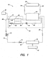
- FIG. 1 there is generally indicated at 10 a system for cooling a space containing, for example, electronic equipment, including closets, equipment rooms and data centers. Such spaces are adapted to house enclosures or racks designed to house networking, telecommunication and other electronic equipment.
- the cooling system 10 may be employed in the type of cooling system disclosed in U.S. Patent Application No. 10/993,329 , entitled IT EQUIPMENT COOLING, filed on November 19, 2004.
- the cooling system 10 of embodiments of the present invention is designed to improve the efficiency and reliability of the entire cooling system by diverting a portion of coolant from a condensing unit to a pump to further sub-cool the coolant being delivered to the pump.
- a medium or coolant such as but not limited to R134A and R410A coolants, is provided within a closed system comprising a main pump 12, which is designed to pump liquid coolant.
- the liquid coolant is disposed within the closed system under increased pressure provided by the main pump 12.
- the main pump 12 may embody two centrifugal pumps placed in series, which are capable of increasing the overall pressure of the coolant between 0.138-0.172 MPa (20-25 psi), for example.
- the pumps may be of the type sold by Tark Incorporated of Dayton, Ohio, under model no. WRD40.5A-23.
- a single pump capable of achieving an overall pressure increase of 0.138-0.172 MPa (20-25 psi) may be provided and still fall within the scope of the present invention.
- the main pump 12 delivers the liquid coolant under increased pressure to an expansion valve 14, which is in fluid communication with the main pump via line 16.
- the expansion valve 14 conditions the coolant so that the coolant experiences a slight pressure and temperature drop after flowing through the expansion valve.
- the expansion valve 14 may be of the type sold by the Sporlan Division of Parker-Hannifm Corporation of Washington, Missouri, under model no. OJE-9-C-5/8"-5/8" ODF-5'.
- the coolant in a form of low pressure liquid/vapor mix (80% liquid and 20% vapor), flows through at least one evaporator unit 18 in fluid communication with the expansion valve 14 via line 20.
- the evaporator unit 18 may take the form of a tubular coil having fins that are adapted to absorb heat from a space, such as hot air taken from the aforementioned closet, equipment room or data center.
- a space such as hot air taken from the aforementioned closet, equipment room or data center.
- Such an evaporator unit 18 may be a micro-channel evaporator having two rows, 25.4 mm micro-channel coil assembly that is manufactured by and commercially available from Heatcraft of Grenada, Mississippi.
- the evaporator unit may be adapted to absorb heat from another medium, such as heated coolant delivered to the evaporator unit, in which the heated medium contains heat taken from the space requiring cooling.
- a heat load 22 from the space requiring cooling is applied to the evaporator unit 18.
- the heat from the heat load 22 which may be in the form of warm air directed by fans from equipment enclosures at the evaporator unit 18, vaporizes the slightly reduced-pressure coolant traveling through the evaporator unit.
- the temperature of the vapor coolant flowing within the evaporator unit 18 is greater than the temperature of the low pressure liquid/vapor mix entering the inlet of the evaporator unit via line 20.
- the resultant pressure of the vapor coolant exiting the evaporator unit 18 is substantially equal to the pressure of the low pressure liquid/vapor mix.
- the vapor coolant which is in super heated condition, flows under relatively low pressure to a condensing unit 24, such as a condensing unit manufactured by WTT America, Inc. of Bohemia, New York under model no. WTT W9-130.
- the condensing unit 24 is in fluid communication with the evaporator unit 18 and the main pump 12 via lines 26, 28, respectively.
- the condensing unit 24 is designed to cool the super heated vapor coolant entering the condensing unit and return the cooled coolant in a liquid state to the main pump 12 via line 28.
- a requirement of the cooling system 10 is that coolant entering the main pump be in a liquid state.
- coolant requiring cooling within the condensing unit 24 may be subjected to a heat exchanger 30 in the form of a chilling unit, which is adapted to provide chilled water (e.g., approximately 7.2°C (45°F) water) in direct fluid communication with the condensing unit via lines 32, 34.
- chilled water e.g., approximately 7.2°C (45°F) water
- the arrangement is such that chilled water entering the condensing unit 24 via line 34 cools the vaporized coolant to a liquid state.
- Warmer water e.g., approximately 11.1°C (52°F) water
- Liquid coolant is then directed from the condensing unit 24 to the main pump 12, where the cycle of pumping, expanding, heating and cooling the coolant begins again.
- a controller 36 such as the controller disclosed in the above-referenced Patent Application No. 10/993,329 , is configured to control the operation of the cooling system 10 illustrated in FIG. 1 .
- the main pump inlet conditions at line 28 are critical in two-phase pumped coolant systems because liquid pumps, such as main pump 12, require 100% liquid. To run efficiently, and to prevent failure of the main pump 12, sub-cooled liquid coolant is desirable. Specifically, as the condensing unit 24 cools vapor coolant via the heat exchanger 30, and "acceptable" liquid coolant (coolant that is sufficiently cooled to liquid phase) is directed to the main pump 12, the acceptable coolant may not be sufficiently cooled for the main pump to operate properly.
- the cooling system 10 with a sub-cooling unit, generally indicated at 40, of an embodiment of the present invention.
- the sub-cooling unit 40 is disposed generally between the condensing unit 24 and the main pump 12 so that it is in fluid communication with these components of the cooling system 10 in the manner described below.
- coolant cooled by the condensing unit 24 is directed to the main pump 12 via line 28.
- a small portion of the coolant is diverted by line 42 to the sub-cooling unit 40 for further cooling.
- the mass of coolant diverted to line 42 is less than 5% of the total mass of coolant delivered to the main pump 12 from the condensing unit 24.
- the mass of coolant diverted to line 42 from the main pump 12 is approximately 2% of the total mass of coolant delivered.
- the controller 36 which is in electrical communication with a valve at 44, may be configured to determine the amount of coolant diverted based on the environmental conditions of the coolant at the main pump 12 and within the sub-cooling unit 40.
- the remaining coolant i.e., the non-diverted coolant, continues to flow to the main pump 12 via line 28.
- the coolant delivered to the main pump 12 is cooled to a sufficiently cool temperature (depending on the type of coolant employed and the environmental conditions impacting the cooling system 10) to ensure the coolant is in a liquid state.
- the coolant flows from the condensing unit 24 through a heat exchanger 46 disposed between the condensing unit 24 and the main pump 12.
- the heat exchanger 46 comprises a co-axial condensing unit having concentric tubes. The arrangement is such that coolant exiting the condensing unit 24 via line 28 flows within an inner tube (not shown) of the co-axial condensing unit 46 and coolant diverted to line 42 flows within an outer tube (not shown) of the co-axial condensing unit that houses the inner tube therein.
- Co-axial condensing units are well known in the art, and may be of the type offered by Packless Industries of Waco, Texas under model no. AES003522. As discussed in greater detail below, it is within this co-axial condensing unit 46 that the coolant flowing from the condensing unit 24 to the main pump 12 by line 28 is cooled by the coolant diverted to the sub-cooling unit 40.
- the sub-cooling unit 40 includes a sub-cooling expansion valve 48 connected to line 42 to reduce the pressure and the temperature of the coolant diverted to the sub-cooling unit.
- the sub-cooling expansion valve 48 may be replaced by a capillary tube or restrictive orifice.
- the sub-cooling expansion valve may be of the type sold by the Sporlan Division of Parker-Hannifin Corporation of Washington, Missouri, under the SJ series of expansion valves.
- the heat exchanger 46 i.e., the co-axial condensing unit
- a sub-cooling pump 54 is in fluid communication with the sub-cooling heat exchanger 46 and the condensing unit 24 via lines 56, 58, respectively, to pump the diverted coolant back to the condensing unit.
- "acceptable" liquid coolant is directed from the condensing unit 24 to the main pump 12 via line 28.
- the valve 44 under manipulation of the controller 36, diverts a small portion of the mass of coolant to the components of the sub-cooling unit 40.
- the valve 44 may be configured to direct a select amount of coolant to the sub-cooling unit by the controller. For example, 2% of the total mass of coolant traveling to the main pump by line 28 may be diverted to the sub-cooling unit 40.
- the diverted coolant is expanded by the sub- cooling expansion valve 48, which significantly reduces the pressure and the temperature of the coolant.
- the sub-cooling heat exchanger 46 is designed to remove heat from the coolant in line 28 directed to the main pump 12 with the diverted sub-cooled coolant thereby ensuring that the coolant being directed to the main pump is in a liquid state.
- the vaporized coolant is pressurized by the liquid/vapor sub-cooling pump 54, which is in fluid communication with the sub-cooling heat exchanger and the condensing unit 24 via lines 56, 58, respectively.
- the pressure of the vaporized coolant is low, thereby requiring the provision of sub-cooling pump 54 to pressurize the coolant to a pressure sufficient for reintroduction into the line 26 carrying coolant from the evaporator(s) unit 18.
- the liquid/vapor coolant is provided under pressure within line 58 and travels to line 26 where it is introduced back into the vaporized coolant traveling from the evaporator unit(s) 18.
- the liquid/vapor pump 54 is a linear piston pump manufactured by Pumpworks Inc. of Minneapolis, Minnesota.
- the pressure of liquid/vapor coolant within line 58 is substantially similar to the pressure of vapor coolant in line 26, and once introduced back into line 26, the coolant travels to the condensing unit 24.
- the sub-cooling unit 40 of the present invention may be employed in any one of the condensing units shown and described in the cooling system disclosed in U.S. Patent Application No. 10/993,329 , entitled IT EQUIPMENT COOLING.
- the sub-cooling unit 40 is particularly effective in ensuring that coolant delivered to a pump is in a liquid state.
- the sub-cooling unit 40 relies on coolant within the closed system to sub- cool the coolant that is delivered to a main pump.
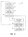
- a method of sub-cooling coolant within a cooling system is generally indicated at 70.
- coolant is pumped to an expansion device, such as expansion valve 14, by a pump, such as main pump 12.
- the expansion device expands the coolant so that the coolant is conditioned to receive a heat load.
- the heat load is applied to the coolant, the heat load being applied from a space requiring cooling, such as a space accommodating electronic equipment.
- the heat load applied to the coolant is typically sufficient to vaporize the coolant.
- the coolant is condensed to a liquid state and directed back to the pump, where the cycle begins again.
- a portion of coolant is diverted to a sub-cooling unit, such as sub-cooling unit 40, which is designed to sub-cool coolant flowing to the pump.
- the method of the present invention may divert a select amount of coolant, e.g., 2% of the coolant flowing to the main pump based on environmental conditions of the coolant exiting the condensing unit.
- the portion of diverted coolant enters a heat exchanger (e.g., heat exchanger 46) to absorb heat from the coolant traveling to the pump. The heat absorbed by the heat exchanger results in the further cooling of the coolant flowing to the pump.
- the diverted portion of coolant is pumped back to the condensing unit at 84, which cools the liquid/vapor coolant.
- sub-cooling unit 40 of embodiments of the present invention may be used cooling systems other than the cooling system 10 illustrated in Figure 1 .
- the sub-cooling unit 40 may be employed in any system, whether a cooling or heating system, having a pump designed to pump liquid coolant. The provision of the sub-cooling unit 40 enables such systems to operate efficiently and more reliably.
Landscapes
- Engineering & Computer Science (AREA)
- Physics & Mathematics (AREA)
- Thermal Sciences (AREA)
- Microelectronics & Electronic Packaging (AREA)
- Mechanical Engineering (AREA)
- General Engineering & Computer Science (AREA)
- Cooling Or The Like Of Electrical Apparatus (AREA)
Applications Claiming Priority (2)
| Application Number | Priority Date | Filing Date | Title |
|---|---|---|---|
| US11/243,628 US7406839B2 (en) | 2005-10-05 | 2005-10-05 | Sub-cooling unit for cooling system and method |
| PCT/US2006/037772 WO2007044235A2 (en) | 2005-10-05 | 2006-09-26 | Sub-cooling unit for cooling system and method |
Publications (2)
| Publication Number | Publication Date |
|---|---|
| EP1943889A2 EP1943889A2 (en) | 2008-07-16 |
| EP1943889B1 true EP1943889B1 (en) | 2014-04-23 |
Family
ID=37862762
Family Applications (1)
| Application Number | Title | Priority Date | Filing Date |
|---|---|---|---|
| EP06825180.0A Active EP1943889B1 (en) | 2005-10-05 | 2006-09-26 | Sub-cooling unit for cooling system and method |
Country Status (10)
| Country | Link |
|---|---|
| US (3) | US7406839B2 (enExample) |
| EP (1) | EP1943889B1 (enExample) |
| JP (1) | JP4902656B2 (enExample) |
| KR (1) | KR101391344B1 (enExample) |
| CN (2) | CN101288354B (enExample) |
| AU (1) | AU2006302679B2 (enExample) |
| CA (1) | CA2624308C (enExample) |
| DK (1) | DK1943889T3 (enExample) |
| ES (1) | ES2477869T3 (enExample) |
| WO (1) | WO2007044235A2 (enExample) |
Families Citing this family (51)
| Publication number | Priority date | Publication date | Assignee | Title |
|---|---|---|---|---|
| JP2008511894A (ja) * | 2004-09-02 | 2008-04-17 | ロジコン デザイン オートメーション エルティーディ. | 電子回路の構造レベル記述を設計する方法及びシステム |
| KR100733295B1 (ko) * | 2004-12-28 | 2007-06-28 | 엘지전자 주식회사 | 냉난방 동시형 멀티 에어컨의 과냉 장치 |
| US7406839B2 (en) | 2005-10-05 | 2008-08-05 | American Power Conversion Corporation | Sub-cooling unit for cooling system and method |
| US7365973B2 (en) * | 2006-01-19 | 2008-04-29 | American Power Conversion Corporation | Cooling system and method |
| US8672732B2 (en) * | 2006-01-19 | 2014-03-18 | Schneider Electric It Corporation | Cooling system and method |
| US20070163748A1 (en) * | 2006-01-19 | 2007-07-19 | American Power Conversion Corporation | Cooling system and method |
| US7681410B1 (en) * | 2006-02-14 | 2010-03-23 | American Power Conversion Corporation | Ice thermal storage |
| US8322155B2 (en) | 2006-08-15 | 2012-12-04 | American Power Conversion Corporation | Method and apparatus for cooling |
| US8327656B2 (en) | 2006-08-15 | 2012-12-11 | American Power Conversion Corporation | Method and apparatus for cooling |
| US20080041077A1 (en) * | 2006-08-15 | 2008-02-21 | American Power Conversion Corporation | Method and apparatus for cooling |
| US9568206B2 (en) | 2006-08-15 | 2017-02-14 | Schneider Electric It Corporation | Method and apparatus for cooling |
| US7861543B2 (en) * | 2006-11-03 | 2011-01-04 | American Power Conversion Corporation | Water carryover avoidance method |
| US20080105753A1 (en) * | 2006-11-03 | 2008-05-08 | American Power Conversion Corporation | Modulating electrical reheat with contactors |
| US20080105412A1 (en) * | 2006-11-03 | 2008-05-08 | American Power Conversion Corporation | Continuous cooling capacity regulation using supplemental heating |
| US20080104985A1 (en) * | 2006-11-03 | 2008-05-08 | American Power Conversion Corporation | Constant temperature CRAC control algorithm |
| US7681404B2 (en) * | 2006-12-18 | 2010-03-23 | American Power Conversion Corporation | Modular ice storage for uninterruptible chilled water |
| US8425287B2 (en) | 2007-01-23 | 2013-04-23 | Schneider Electric It Corporation | In-row air containment and cooling system and method |
| EP2147585B1 (en) | 2007-05-15 | 2016-11-02 | Schneider Electric IT Corporation | Method and system for managing facility power and cooling |
| US20090019875A1 (en) * | 2007-07-19 | 2009-01-22 | American Power Conversion Corporation | A/v cooling system and method |
| US7864530B1 (en) | 2007-09-28 | 2011-01-04 | Exaflop Llc | Changing data center cooling modes |
| US8701746B2 (en) | 2008-03-13 | 2014-04-22 | Schneider Electric It Corporation | Optically detected liquid depth information in a climate control unit |
| GB2464121B (en) * | 2008-10-03 | 2010-10-13 | Energyexcel Llp | Method and Apparatus for Integrating Absorption Cooling into a Refrigeration System |
| US8146374B1 (en) * | 2009-02-13 | 2012-04-03 | Source IT Energy, LLC | System and method for efficient utilization of energy generated by a utility plant |
| US8219362B2 (en) | 2009-05-08 | 2012-07-10 | American Power Conversion Corporation | System and method for arranging equipment in a data center |
| WO2010137120A1 (ja) * | 2009-05-26 | 2010-12-02 | 三菱電機株式会社 | ヒートポンプ式給湯装置 |
| US8973380B2 (en) * | 2009-05-28 | 2015-03-10 | Schneider Electric It Corporation | Systems and methods for detecting refrigerant leaks in cooling systems |
| EP2532215B1 (en) * | 2010-02-02 | 2021-05-05 | Google LLC | Blended water-based data center cooling |
| AU2011270812C1 (en) * | 2010-06-23 | 2017-05-11 | Inertech Ip Llc | Space-saving high-density modular data center and an energy-efficient cooling system |
| US8402816B2 (en) | 2010-12-30 | 2013-03-26 | Schneider Electric It Corporation | Systems and methods for detecting leaks |
| US8688413B2 (en) | 2010-12-30 | 2014-04-01 | Christopher M. Healey | System and method for sequential placement of cooling resources within data center layouts |
| US9845981B2 (en) | 2011-04-19 | 2017-12-19 | Liebert Corporation | Load estimator for control of vapor compression cooling system with pumped refrigerant economization |
| US9038404B2 (en) | 2011-04-19 | 2015-05-26 | Liebert Corporation | High efficiency cooling system |
| US8881541B2 (en) | 2011-04-19 | 2014-11-11 | Liebert Corporation | Cooling system with tandem compressors and electronic expansion valve control |
| JP5806581B2 (ja) | 2011-10-18 | 2015-11-10 | 株式会社日立製作所 | 冷却システム及び冷却方法 |
| AU2011383606A1 (en) | 2011-12-22 | 2014-07-17 | Schneider Electric It Corporation | System and method for prediction of temperature values in an electronics system |
| EP2795489A4 (en) | 2011-12-22 | 2016-06-01 | Schneider Electric It Corp | ANALYSIS OF THE IMPACT OF TRANSITION EVENTS ON THE TEMPERATURE IN A DATA CENTER |
| US20130239603A1 (en) * | 2012-03-15 | 2013-09-19 | Luther D. Albertson | Heat pump with independent subcooler circuit |
| WO2014011706A1 (en) | 2012-07-09 | 2014-01-16 | Inertech Ip Llc | Transformerless multi-level medium-voltage uninterruptible power supply (ups) systems and methods |
| WO2014059054A1 (en) | 2012-10-09 | 2014-04-17 | Inertech Ip Llc | Cooling systems and methods incorporating a plural in-series pumped liquid refrigerant trim evaporator cycle |
| US9774190B2 (en) | 2013-09-09 | 2017-09-26 | Inertech Ip Llc | Multi-level medium voltage data center static synchronous compensator (DCSTATCOM) for active and reactive power control of data centers connected with grid energy storage and smart green distributed energy sources |
| US10254021B2 (en) | 2013-10-21 | 2019-04-09 | Inertech Ip Llc | Cooling systems and methods using two cooling circuits |
| US11306959B2 (en) | 2013-11-06 | 2022-04-19 | Inertech Ip Llc | Cooling systems and methods using two circuits with water flow in series and counter flow arrangement |
| AU2015317282A1 (en) | 2014-09-19 | 2017-03-16 | Axiom Thermal Inc. | Systems and methods implementing robust air conditioning systems configured to utilize thermal energy storage to maintain a low temperature for a target space |
| WO2016057854A1 (en) | 2014-10-08 | 2016-04-14 | Inertech Ip Llc | Systems and methods for cooling electrical equipment |
| WO2016065087A1 (en) | 2014-10-21 | 2016-04-28 | Inertech Ip Llc | Systems and methods for controlling multi-level diode-clamped inverters using space vector pulse width modulation (svpwm) |
| US10193380B2 (en) | 2015-01-13 | 2019-01-29 | Inertech Ip Llc | Power sources and systems utilizing a common ultra-capacitor and battery hybrid energy storage system for both uninterruptible power supply and generator start-up functions |
| US10931190B2 (en) | 2015-10-22 | 2021-02-23 | Inertech Ip Llc | Systems and methods for mitigating harmonics in electrical systems by using active and passive filtering techniques |
| WO2018089130A1 (en) | 2016-11-11 | 2018-05-17 | Stulz Air Technology Systems, Inc. | Dual mass cooling precision system |
| US11202392B2 (en) | 2019-10-16 | 2021-12-14 | International Business Machines Corporation | Multi-coolant heat exchanger for an electronics rack |
| US11937405B2 (en) * | 2021-04-30 | 2024-03-19 | Quanta Computer Inc. | Systems and methods for cooling a fluid circuit for cooling a rack of servers |
| US20210320048A1 (en) * | 2021-06-24 | 2021-10-14 | Intel Corporation | Cold plate with integrated vapor chamber |
Family Cites Families (98)
| Publication number | Priority date | Publication date | Assignee | Title |
|---|---|---|---|---|
| US3559728A (en) | 1968-11-29 | 1971-02-02 | Kooltronic Fan Co | Electronic equipment rack temperature control |
| US3681936A (en) * | 1970-10-26 | 1972-08-08 | Oklahoma Mfg Co | Heat exchanger |
| US4127008A (en) | 1976-11-01 | 1978-11-28 | Lewis Tyree Jr | Method and apparatus for cooling material using liquid CO2 |
| US4197716A (en) | 1977-09-14 | 1980-04-15 | Halstead Industries, Inc. | Refrigeration system with auxiliary heat exchanger for supplying heat during defrost cycle and for subcooling the refrigerant during a refrigeration cycle |
| US4285205A (en) | 1979-12-20 | 1981-08-25 | Martin Leonard I | Refrigerant sub-cooling |
| US4275570A (en) * | 1980-06-16 | 1981-06-30 | Vilter Manufacturing Corporation | Oil cooling means for refrigeration screw compressor |
| JPS57179544A (en) * | 1981-04-24 | 1982-11-05 | Nippon Denso Co | Refrigerating cycle |
| US4419865A (en) * | 1981-12-31 | 1983-12-13 | Vilter Manufacturing Company | Oil cooling apparatus for refrigeration screw compressor |
| US4590538A (en) | 1982-11-18 | 1986-05-20 | Cray Research, Inc. | Immersion cooled high density electronic assembly |
| US4515746A (en) | 1983-09-06 | 1985-05-07 | General Electric Company | Microcomposite of metal carbide and ceramic particles |
| US4599873A (en) * | 1984-01-31 | 1986-07-15 | Hyde Robert E | Apparatus for maximizing refrigeration capacity |
| KR900001842B1 (ko) | 1984-11-15 | 1990-03-24 | 후지쓰 가부시끼가이샤 | 전자장비용 랙의 냉각구조 |
| US4696168A (en) * | 1986-10-01 | 1987-09-29 | Roger Rasbach | Refrigerant subcooler for air conditioning systems |
| JPH0770853B2 (ja) | 1987-01-21 | 1995-07-31 | 株式会社日立製作所 | 電子装置の冷却装置 |
| GB8724263D0 (en) | 1987-10-15 | 1987-11-18 | Bicc Plc | Electronic enclosure cooling system |
| CA1334016C (en) * | 1987-10-26 | 1995-01-17 | Brian Hartley Keane | Low pressure distillation apparatus |
| US5173819A (en) | 1988-10-05 | 1992-12-22 | Hitachi, Ltd. | Disk apparatus having an improved cooling structure |
| FR2646579A1 (fr) | 1989-03-20 | 1990-11-02 | Guillemot Gerard | Equipement chauffant electriquement a haute temperature par zones regulees pour la mise en oeuvre de produits en materiaux composites |
| US5057968A (en) | 1989-10-16 | 1991-10-15 | Lockheed Corporation | Cooling system for electronic modules |
| US5088292A (en) * | 1990-07-10 | 1992-02-18 | Sundstrand Corporation | Bearing pump control for lubricating hydrodynamic compressor bearings |
| US5150580A (en) * | 1991-03-08 | 1992-09-29 | Hyde Robert E | Liquid pressure amplification with superheat suppression |
| US5095712A (en) * | 1991-05-03 | 1992-03-17 | Carrier Corporation | Economizer control with variable capacity |
| US5174123A (en) * | 1991-08-23 | 1992-12-29 | Thermo King Corporation | Methods and apparatus for operating a refrigeration system |
| US5177666A (en) | 1991-10-24 | 1993-01-05 | Bland Timothy J | Cooling rack for electronic devices |
| US5383339A (en) * | 1992-12-10 | 1995-01-24 | Baltimore Aircoil Company, Inc. | Supplemental cooling system for coupling to refrigerant-cooled apparatus |
| US5649428A (en) | 1993-01-08 | 1997-07-22 | Engelhard/Icc | Hybrid air-conditioning system with improved recovery evaporator and subcool condenser coils |
| JPH06241584A (ja) * | 1993-02-19 | 1994-08-30 | Mitsubishi Electric Corp | 冷凍サイクル |
| US5972196A (en) | 1995-06-07 | 1999-10-26 | Lynntech, Inc. | Electrochemical production of ozone and hydrogen peroxide |
| US5749237A (en) * | 1993-09-28 | 1998-05-12 | Jdm, Ltd. | Refrigerant system flash gas suppressor with variable speed drive |
| US5582020A (en) * | 1994-11-23 | 1996-12-10 | Mainstream Engineering Corporation | Chemical/mechanical system and method using two-phase/two-component compression heat pump |
| JP2694515B2 (ja) * | 1995-03-01 | 1997-12-24 | エス・ティエス株式会社 | 冷却装置 |
| US5657641A (en) | 1995-09-13 | 1997-08-19 | Kooltronic, Inc. | Panel mounted cooling system |
| US5694780A (en) * | 1995-12-01 | 1997-12-09 | Alsenz; Richard H. | Condensed liquid pump for compressor body cooling |
| US6032472A (en) * | 1995-12-06 | 2000-03-07 | Carrier Corporation | Motor cooling in a refrigeration system |
| US6111036A (en) * | 1996-10-17 | 2000-08-29 | Eastman Chemical Company | Method for improving cooling of fluid bed polymer reactor |
| US5967283A (en) | 1996-12-04 | 1999-10-19 | Kemper; Yves J. | Clutch spring assembly |
| US6213194B1 (en) | 1997-07-16 | 2001-04-10 | International Business Machines Corporation | Hybrid cooling system for electronics module |
| US6047556A (en) * | 1997-12-08 | 2000-04-11 | Carrier Corporation | Pulsed flow for capacity control |
| JPH11254957A (ja) * | 1998-03-16 | 1999-09-21 | Nippon Climate Systems Corp | 車両用ヒートポンプ式空調装置 |
| US6170270B1 (en) * | 1999-01-29 | 2001-01-09 | Delaware Capital Formation, Inc. | Refrigeration system using liquid-to-liquid heat transfer for warm liquid defrost |
| CN2371768Y (zh) * | 1999-04-06 | 2000-03-29 | 陈俊良 | 辅助散热循环系统 |
| US6237353B1 (en) * | 1999-07-29 | 2001-05-29 | Carrier Corporation | System for removing parasitic losses in a refrigeration unit |
| GB2354062A (en) | 1999-09-13 | 2001-03-14 | British Broadcasting Corp | Cooling system for use in cooling electronic equipment |
| WO2001062060A1 (en) | 2000-02-18 | 2001-08-23 | Rtkl Associates Inc. | Computer rack heat extraction device |
| EP1266548B2 (en) | 2000-03-21 | 2015-07-29 | Liebert Corporation | Method and apparatus for cooling electronic enclosures |
| JP2001260640A (ja) * | 2000-03-21 | 2001-09-26 | Calsonic Kansei Corp | 車両用暖房装置 |
| US6374631B1 (en) * | 2000-03-27 | 2002-04-23 | Carrier Corporation | Economizer circuit enhancement |
| JP2002156161A (ja) * | 2000-11-16 | 2002-05-31 | Mitsubishi Heavy Ind Ltd | 空気調和装置 |
| US6459579B1 (en) | 2001-01-03 | 2002-10-01 | Juniper Networks, Inc. | Apparatus and method for directing airflow in three dimensions to cool system components |
| US6967283B2 (en) | 2001-03-20 | 2005-11-22 | American Power Conversion Corporation | Adjustable scalable rack power system and method |
| US6848989B2 (en) | 2001-05-30 | 2005-02-01 | Kongo Kabushiki Kaisha | Environmental improvement device for a storage body |
| US6718781B2 (en) * | 2001-07-11 | 2004-04-13 | Thermo King Corporation | Refrigeration unit apparatus and method |
| US20030042004A1 (en) | 2001-08-29 | 2003-03-06 | Shlomo Novotny | Interchangeable cartridges for cooling electronic components |
| JP4442068B2 (ja) * | 2001-09-12 | 2010-03-31 | 三菱電機株式会社 | 冷凍空調装置 |
| US6474087B1 (en) * | 2001-10-03 | 2002-11-05 | Carrier Corporation | Method and apparatus for the control of economizer circuit flow for optimum performance |
| DE10302356A1 (de) * | 2002-01-30 | 2003-07-31 | Denso Corp | Kältekreislauf mit Ejektorpumpe |
| GB0207382D0 (en) | 2002-03-28 | 2002-05-08 | Holland Heating Uk Ltd | Computer cabinet |
| US6625019B1 (en) | 2002-04-01 | 2003-09-23 | White Rock Networks | Systems and methods for a rack-mounted communications switch component |
| US6668565B1 (en) | 2002-04-12 | 2003-12-30 | American Power Conversion | Rack-mounted equipment cooling |
| US6695577B1 (en) | 2002-08-13 | 2004-02-24 | American Power Conversion | Fan grill |
| US6662576B1 (en) * | 2002-09-23 | 2003-12-16 | Vai Holdings Llc | Refrigeration system with de-superheating bypass |
| US6871509B2 (en) * | 2002-10-02 | 2005-03-29 | Carrier Corporation | Enhanced cooling system |
| US7752858B2 (en) | 2002-11-25 | 2010-07-13 | American Power Conversion Corporation | Exhaust air removal system |
| US7500911B2 (en) | 2002-11-25 | 2009-03-10 | American Power Conversion Corporation | Exhaust air removal system |
| US6775137B2 (en) | 2002-11-25 | 2004-08-10 | International Business Machines Corporation | Method and apparatus for combined air and liquid cooling of stacked electronics components |
| US20040112978A1 (en) | 2002-12-19 | 2004-06-17 | Reichel Charles A. | Apparatus for high-throughput non-contact liquid transfer and uses thereof |
| US6745590B1 (en) | 2003-01-13 | 2004-06-08 | American Power Conversion | Condensate removal system |
| US6859366B2 (en) | 2003-03-19 | 2005-02-22 | American Power Conversion | Data center cooling system |
| US7046514B2 (en) | 2003-03-19 | 2006-05-16 | American Power Conversion Corporation | Data center cooling |
| WO2004090679A2 (en) | 2003-04-14 | 2004-10-21 | Netbotz, Inc. | Environmental monitoring device |
| US7033267B2 (en) | 2003-05-13 | 2006-04-25 | American Power Conversion Corporation | Rack enclosure |
| US7112131B2 (en) | 2003-05-13 | 2006-09-26 | American Power Conversion Corporation | Rack enclosure |
| US7508672B2 (en) | 2003-09-10 | 2009-03-24 | Qnx Cooling Systems Inc. | Cooling system |
| US7162878B2 (en) * | 2003-10-15 | 2007-01-16 | Ice Energy, Llc | Refrigeration apparatus |
| US7017357B2 (en) * | 2003-11-18 | 2006-03-28 | Carrier Corporation | Emergency power generation system |
| US7106590B2 (en) | 2003-12-03 | 2006-09-12 | International Business Machines Corporation | Cooling system and method employing multiple dedicated coolant conditioning units for cooling multiple electronics subsystems |
| US7278273B1 (en) | 2003-12-30 | 2007-10-09 | Google Inc. | Modular data center |
| US6955058B2 (en) * | 2004-01-30 | 2005-10-18 | Carrier Corporation | Refrigerant cycle with tandem economized and conventional compressors |
| US20050237716A1 (en) | 2004-04-21 | 2005-10-27 | International Business Machines Corporation | Air flow system and method for facilitating cooling of stacked electronics components |
| US7233492B2 (en) | 2004-04-22 | 2007-06-19 | Hewlett-Packard Development Company, L.P. | Cooling systems and methods for same |
| US6973797B2 (en) * | 2004-05-10 | 2005-12-13 | York International Corporation | Capacity control for economizer refrigeration systems |
| US8341965B2 (en) | 2004-06-24 | 2013-01-01 | Raytheon Company | Method and system for cooling |
| US20060082263A1 (en) | 2004-10-15 | 2006-04-20 | American Power Conversion Corporation | Mobile data center |
| US7228707B2 (en) * | 2004-10-28 | 2007-06-12 | Carrier Corporation | Hybrid tandem compressor system with multiple evaporators and economizer circuit |
| US7293666B2 (en) | 2004-11-17 | 2007-11-13 | American Power Conversion Corporation | Equipment enclosure kit and assembly method |
| US7165412B1 (en) | 2004-11-19 | 2007-01-23 | American Power Conversion Corporation | IT equipment cooling |
| US7184269B2 (en) | 2004-12-09 | 2007-02-27 | International Business Machines Company | Cooling apparatus and method for an electronics module employing an integrated heat exchange assembly |
| US7259963B2 (en) | 2004-12-29 | 2007-08-21 | American Power Conversion Corp. | Rack height cooling |
| US7603874B2 (en) | 2005-01-24 | 2009-10-20 | American Power Conversion Corporation | Split power input to chiller |
| US7385810B2 (en) | 2005-04-18 | 2008-06-10 | International Business Machines Corporation | Apparatus and method for facilitating cooling of an electronics rack employing a heat exchange assembly mounted to an outlet door cover of the electronics rack |
| US7885795B2 (en) | 2005-05-02 | 2011-02-08 | American Power Conversion Corporation | Methods and systems for managing facility power and cooling |
| US7881910B2 (en) | 2005-05-02 | 2011-02-01 | American Power Conversion Corporation | Methods and systems for managing facility power and cooling |
| US7596476B2 (en) | 2005-05-02 | 2009-09-29 | American Power Conversion Corporation | Methods and systems for managing facility power and cooling |
| US7841199B2 (en) | 2005-05-17 | 2010-11-30 | American Power Conversion Corporation | Cold aisle isolation |
| US7406839B2 (en) | 2005-10-05 | 2008-08-05 | American Power Conversion Corporation | Sub-cooling unit for cooling system and method |
| US20070163748A1 (en) | 2006-01-19 | 2007-07-19 | American Power Conversion Corporation | Cooling system and method |
| US8672732B2 (en) | 2006-01-19 | 2014-03-18 | Schneider Electric It Corporation | Cooling system and method |
| US7365973B2 (en) | 2006-01-19 | 2008-04-29 | American Power Conversion Corporation | Cooling system and method |
-
2005
- 2005-10-05 US US11/243,628 patent/US7406839B2/en active Active
-
2006
- 2006-09-26 CN CN2006800365292A patent/CN101288354B/zh active Active
- 2006-09-26 CN CN201210310350.9A patent/CN103002711B/zh active Active
- 2006-09-26 CA CA2624308A patent/CA2624308C/en not_active Expired - Fee Related
- 2006-09-26 AU AU2006302679A patent/AU2006302679B2/en not_active Ceased
- 2006-09-26 WO PCT/US2006/037772 patent/WO2007044235A2/en not_active Ceased
- 2006-09-26 DK DK06825180.0T patent/DK1943889T3/da active
- 2006-09-26 KR KR1020087010635A patent/KR101391344B1/ko active Active
- 2006-09-26 JP JP2008534566A patent/JP4902656B2/ja not_active Expired - Fee Related
- 2006-09-26 EP EP06825180.0A patent/EP1943889B1/en active Active
- 2006-09-26 ES ES06825180.0T patent/ES2477869T3/es active Active
-
2008
- 2008-07-29 US US12/181,714 patent/US7775055B2/en active Active
-
2010
- 2010-08-16 US US12/857,213 patent/US8347641B2/en active Active
Also Published As
| Publication number | Publication date |
|---|---|
| US20110023508A1 (en) | 2011-02-03 |
| CN101288354A (zh) | 2008-10-15 |
| AU2006302679B2 (en) | 2010-04-22 |
| WO2007044235A3 (en) | 2007-09-13 |
| ES2477869T3 (es) | 2014-07-18 |
| CN103002711A (zh) | 2013-03-27 |
| KR20080082607A (ko) | 2008-09-11 |
| JP4902656B2 (ja) | 2012-03-21 |
| CN103002711B (zh) | 2015-07-22 |
| US7406839B2 (en) | 2008-08-05 |
| EP1943889A2 (en) | 2008-07-16 |
| AU2006302679A1 (en) | 2007-04-19 |
| US7775055B2 (en) | 2010-08-17 |
| CN101288354B (zh) | 2012-10-10 |
| CA2624308C (en) | 2015-04-14 |
| JP2009512190A (ja) | 2009-03-19 |
| DK1943889T3 (da) | 2014-06-30 |
| US8347641B2 (en) | 2013-01-08 |
| US20070074537A1 (en) | 2007-04-05 |
| CA2624308A1 (en) | 2007-04-19 |
| US20090007591A1 (en) | 2009-01-08 |
| WO2007044235A2 (en) | 2007-04-19 |
| KR101391344B1 (ko) | 2014-05-26 |
Similar Documents
| Publication | Publication Date | Title |
|---|---|---|
| EP1943889B1 (en) | Sub-cooling unit for cooling system and method | |
| JP2009512190A5 (enExample) | ||
| US8441789B2 (en) | Data center module | |
| US20070209782A1 (en) | System and method for cooling a server-based data center with sub-ambient cooling | |
| US9772126B2 (en) | Cooling system for high density heat load | |
| USRE45111E1 (en) | IT equipment cooling | |
| US9854714B2 (en) | Method of absorbing sensible and latent heat with series-connected heat sinks | |
| EP1380799A2 (en) | Method and apparatus for cooling with coolant at a subambient pressure | |
| US20120048514A1 (en) | Cooling systems and methods | |
| US10893633B2 (en) | Method of cooling an electronics cabinet | |
| US9448001B2 (en) | Indirect cooling unit | |
| WO2016069271A1 (en) | Method of absorbing heat with series-connected heat sink modules | |
| CN103135666A (zh) | 集装箱式数据中心装置 | |
| EP2780648B1 (en) | Hybrid refrigerant circulating cooling system | |
| CN223193327U (zh) | 制冷系统 | |
| CN110375451A (zh) | 用于高密度热负载的改进的冷却系统 | |
| MX2008014702A (es) | Manejo de temperatura para componentes electronicos. |
Legal Events
| Date | Code | Title | Description |
|---|---|---|---|
| PUAI | Public reference made under article 153(3) epc to a published international application that has entered the european phase |
Free format text: ORIGINAL CODE: 0009012 |
|
| 17P | Request for examination filed |
Effective date: 20080325 |
|
| AK | Designated contracting states |
Kind code of ref document: A2 Designated state(s): AT BE BG CH CY CZ DE DK EE ES FI FR GB GR HU IE IS IT LI LT LU LV MC NL PL PT RO SE SI SK TR |
|
| RIN1 | Information on inventor provided before grant (corrected) |
Inventor name: BEAN, JOHN, H. Inventor name: LOMAS, JONATHAN, M. |
|
| 17Q | First examination report despatched |
Effective date: 20100211 |
|
| DAX | Request for extension of the european patent (deleted) | ||
| GRAP | Despatch of communication of intention to grant a patent |
Free format text: ORIGINAL CODE: EPIDOSNIGR1 |
|
| INTG | Intention to grant announced |
Effective date: 20131111 |
|
| RIN1 | Information on inventor provided before grant (corrected) |
Inventor name: BEAN, JOHN, H. Inventor name: LOMAS, JONATHAN, M. |
|
| GRAS | Grant fee paid |
Free format text: ORIGINAL CODE: EPIDOSNIGR3 |
|
| GRAA | (expected) grant |
Free format text: ORIGINAL CODE: 0009210 |
|
| AK | Designated contracting states |
Kind code of ref document: B1 Designated state(s): AT BE BG CH CY CZ DE DK EE ES FI FR GB GR HU IE IS IT LI LT LU LV MC NL PL PT RO SE SI SK TR |
|
| RAP1 | Party data changed (applicant data changed or rights of an application transferred) |
Owner name: SCHNEIDER ELECTRIC IT CORPORATION |
|
| REG | Reference to a national code |
Ref country code: GB Ref legal event code: FG4D |
|
| REG | Reference to a national code |
Ref country code: CH Ref legal event code: EP |
|
| REG | Reference to a national code |
Ref country code: AT Ref legal event code: REF Ref document number: 664472 Country of ref document: AT Kind code of ref document: T Effective date: 20140515 |
|
| REG | Reference to a national code |
Ref country code: IE Ref legal event code: FG4D |
|
| REG | Reference to a national code |
Ref country code: DE Ref legal event code: R096 Ref document number: 602006041244 Country of ref document: DE Effective date: 20140605 |
|
| REG | Reference to a national code |
Ref country code: DK Ref legal event code: T3 Effective date: 20140623 |
|
| REG | Reference to a national code |
Ref country code: ES Ref legal event code: FG2A Ref document number: 2477869 Country of ref document: ES Kind code of ref document: T3 Effective date: 20140718 |
|
| REG | Reference to a national code |
Ref country code: NL Ref legal event code: VDEP Effective date: 20140423 |
|
| REG | Reference to a national code |
Ref country code: LT Ref legal event code: MG4D |
|
| PG25 | Lapsed in a contracting state [announced via postgrant information from national office to epo] |
Ref country code: NL Free format text: LAPSE BECAUSE OF FAILURE TO SUBMIT A TRANSLATION OF THE DESCRIPTION OR TO PAY THE FEE WITHIN THE PRESCRIBED TIME-LIMIT Effective date: 20140423 Ref country code: CY Free format text: LAPSE BECAUSE OF FAILURE TO SUBMIT A TRANSLATION OF THE DESCRIPTION OR TO PAY THE FEE WITHIN THE PRESCRIBED TIME-LIMIT Effective date: 20140423 Ref country code: GR Free format text: LAPSE BECAUSE OF FAILURE TO SUBMIT A TRANSLATION OF THE DESCRIPTION OR TO PAY THE FEE WITHIN THE PRESCRIBED TIME-LIMIT Effective date: 20140724 Ref country code: IS Free format text: LAPSE BECAUSE OF FAILURE TO SUBMIT A TRANSLATION OF THE DESCRIPTION OR TO PAY THE FEE WITHIN THE PRESCRIBED TIME-LIMIT Effective date: 20140823 Ref country code: FI Free format text: LAPSE BECAUSE OF FAILURE TO SUBMIT A TRANSLATION OF THE DESCRIPTION OR TO PAY THE FEE WITHIN THE PRESCRIBED TIME-LIMIT Effective date: 20140423 Ref country code: BG Free format text: LAPSE BECAUSE OF FAILURE TO SUBMIT A TRANSLATION OF THE DESCRIPTION OR TO PAY THE FEE WITHIN THE PRESCRIBED TIME-LIMIT Effective date: 20140723 Ref country code: LT Free format text: LAPSE BECAUSE OF FAILURE TO SUBMIT A TRANSLATION OF THE DESCRIPTION OR TO PAY THE FEE WITHIN THE PRESCRIBED TIME-LIMIT Effective date: 20140423 |
|
| PG25 | Lapsed in a contracting state [announced via postgrant information from national office to epo] |
Ref country code: SE Free format text: LAPSE BECAUSE OF FAILURE TO SUBMIT A TRANSLATION OF THE DESCRIPTION OR TO PAY THE FEE WITHIN THE PRESCRIBED TIME-LIMIT Effective date: 20140423 Ref country code: PL Free format text: LAPSE BECAUSE OF FAILURE TO SUBMIT A TRANSLATION OF THE DESCRIPTION OR TO PAY THE FEE WITHIN THE PRESCRIBED TIME-LIMIT Effective date: 20140423 Ref country code: LV Free format text: LAPSE BECAUSE OF FAILURE TO SUBMIT A TRANSLATION OF THE DESCRIPTION OR TO PAY THE FEE WITHIN THE PRESCRIBED TIME-LIMIT Effective date: 20140423 |
|
| PG25 | Lapsed in a contracting state [announced via postgrant information from national office to epo] |
Ref country code: PT Free format text: LAPSE BECAUSE OF FAILURE TO SUBMIT A TRANSLATION OF THE DESCRIPTION OR TO PAY THE FEE WITHIN THE PRESCRIBED TIME-LIMIT Effective date: 20140825 |
|
| REG | Reference to a national code |
Ref country code: DE Ref legal event code: R097 Ref document number: 602006041244 Country of ref document: DE |
|
| PG25 | Lapsed in a contracting state [announced via postgrant information from national office to epo] |
Ref country code: CZ Free format text: LAPSE BECAUSE OF FAILURE TO SUBMIT A TRANSLATION OF THE DESCRIPTION OR TO PAY THE FEE WITHIN THE PRESCRIBED TIME-LIMIT Effective date: 20140423 Ref country code: RO Free format text: LAPSE BECAUSE OF FAILURE TO SUBMIT A TRANSLATION OF THE DESCRIPTION OR TO PAY THE FEE WITHIN THE PRESCRIBED TIME-LIMIT Effective date: 20140423 Ref country code: EE Free format text: LAPSE BECAUSE OF FAILURE TO SUBMIT A TRANSLATION OF THE DESCRIPTION OR TO PAY THE FEE WITHIN THE PRESCRIBED TIME-LIMIT Effective date: 20140423 Ref country code: SK Free format text: LAPSE BECAUSE OF FAILURE TO SUBMIT A TRANSLATION OF THE DESCRIPTION OR TO PAY THE FEE WITHIN THE PRESCRIBED TIME-LIMIT Effective date: 20140423 Ref country code: BE Free format text: LAPSE BECAUSE OF FAILURE TO SUBMIT A TRANSLATION OF THE DESCRIPTION OR TO PAY THE FEE WITHIN THE PRESCRIBED TIME-LIMIT Effective date: 20140423 |
|
| PLBE | No opposition filed within time limit |
Free format text: ORIGINAL CODE: 0009261 |
|
| STAA | Information on the status of an ep patent application or granted ep patent |
Free format text: STATUS: NO OPPOSITION FILED WITHIN TIME LIMIT |
|
| 26N | No opposition filed |
Effective date: 20150126 |
|
| PG25 | Lapsed in a contracting state [announced via postgrant information from national office to epo] |
Ref country code: LU Free format text: LAPSE BECAUSE OF FAILURE TO SUBMIT A TRANSLATION OF THE DESCRIPTION OR TO PAY THE FEE WITHIN THE PRESCRIBED TIME-LIMIT Effective date: 20140926 Ref country code: MC Free format text: LAPSE BECAUSE OF FAILURE TO SUBMIT A TRANSLATION OF THE DESCRIPTION OR TO PAY THE FEE WITHIN THE PRESCRIBED TIME-LIMIT Effective date: 20140423 |
|
| REG | Reference to a national code |
Ref country code: CH Ref legal event code: PL |
|
| REG | Reference to a national code |
Ref country code: DE Ref legal event code: R097 Ref document number: 602006041244 Country of ref document: DE Effective date: 20150126 |
|
| REG | Reference to a national code |
Ref country code: IE Ref legal event code: MM4A |
|
| PG25 | Lapsed in a contracting state [announced via postgrant information from national office to epo] |
Ref country code: LI Free format text: LAPSE BECAUSE OF NON-PAYMENT OF DUE FEES Effective date: 20140930 Ref country code: SI Free format text: LAPSE BECAUSE OF FAILURE TO SUBMIT A TRANSLATION OF THE DESCRIPTION OR TO PAY THE FEE WITHIN THE PRESCRIBED TIME-LIMIT Effective date: 20140423 Ref country code: CH Free format text: LAPSE BECAUSE OF NON-PAYMENT OF DUE FEES Effective date: 20140930 |
|
| PG25 | Lapsed in a contracting state [announced via postgrant information from national office to epo] |
Ref country code: IE Free format text: LAPSE BECAUSE OF NON-PAYMENT OF DUE FEES Effective date: 20140926 |
|
| PG25 | Lapsed in a contracting state [announced via postgrant information from national office to epo] |
Ref country code: HU Free format text: LAPSE BECAUSE OF FAILURE TO SUBMIT A TRANSLATION OF THE DESCRIPTION OR TO PAY THE FEE WITHIN THE PRESCRIBED TIME-LIMIT; INVALID AB INITIO Effective date: 20060926 Ref country code: TR Free format text: LAPSE BECAUSE OF FAILURE TO SUBMIT A TRANSLATION OF THE DESCRIPTION OR TO PAY THE FEE WITHIN THE PRESCRIBED TIME-LIMIT Effective date: 20140423 |
|
| REG | Reference to a national code |
Ref country code: FR Ref legal event code: PLFP Year of fee payment: 11 |
|
| PGFP | Annual fee paid to national office [announced via postgrant information from national office to epo] |
Ref country code: ES Payment date: 20160926 Year of fee payment: 11 |
|
| REG | Reference to a national code |
Ref country code: FR Ref legal event code: PLFP Year of fee payment: 12 |
|
| REG | Reference to a national code |
Ref country code: DE Ref legal event code: R082 Ref document number: 602006041244 Country of ref document: DE Representative=s name: MURGITROYD & COMPANY, DE |
|
| PGFP | Annual fee paid to national office [announced via postgrant information from national office to epo] |
Ref country code: AT Payment date: 20170901 Year of fee payment: 12 |
|
| REG | Reference to a national code |
Ref country code: FR Ref legal event code: PLFP Year of fee payment: 13 |
|
| REG | Reference to a national code |
Ref country code: ES Ref legal event code: FD2A Effective date: 20181017 |
|
| PG25 | Lapsed in a contracting state [announced via postgrant information from national office to epo] |
Ref country code: ES Free format text: LAPSE BECAUSE OF NON-PAYMENT OF DUE FEES Effective date: 20170927 |
|
| REG | Reference to a national code |
Ref country code: AT Ref legal event code: MM01 Ref document number: 664472 Country of ref document: AT Kind code of ref document: T Effective date: 20180926 |
|
| PG25 | Lapsed in a contracting state [announced via postgrant information from national office to epo] |
Ref country code: AT Free format text: LAPSE BECAUSE OF NON-PAYMENT OF DUE FEES Effective date: 20180926 |
|
| PGFP | Annual fee paid to national office [announced via postgrant information from national office to epo] |
Ref country code: DE Payment date: 20240926 Year of fee payment: 19 |
|
| PGFP | Annual fee paid to national office [announced via postgrant information from national office to epo] |
Ref country code: DK Payment date: 20240925 Year of fee payment: 19 |
|
| PGFP | Annual fee paid to national office [announced via postgrant information from national office to epo] |
Ref country code: GB Payment date: 20240924 Year of fee payment: 19 |
|
| PGFP | Annual fee paid to national office [announced via postgrant information from national office to epo] |
Ref country code: FR Payment date: 20240925 Year of fee payment: 19 |
|
| PGFP | Annual fee paid to national office [announced via postgrant information from national office to epo] |
Ref country code: IT Payment date: 20240924 Year of fee payment: 19 |