EP1942314A1 - Navigation system - Google Patents
Navigation system Download PDFInfo
- Publication number
- EP1942314A1 EP1942314A1 EP06811915A EP06811915A EP1942314A1 EP 1942314 A1 EP1942314 A1 EP 1942314A1 EP 06811915 A EP06811915 A EP 06811915A EP 06811915 A EP06811915 A EP 06811915A EP 1942314 A1 EP1942314 A1 EP 1942314A1
- Authority
- EP
- European Patent Office
- Prior art keywords
- guide
- distance
- intersection
- route
- navigation system
- Prior art date
- Legal status (The legal status is an assumption and is not a legal conclusion. Google has not performed a legal analysis and makes no representation as to the accuracy of the status listed.)
- Granted
Links
- 238000010586 diagram Methods 0.000 description 18
- 238000012545 processing Methods 0.000 description 18
- 238000013459 approach Methods 0.000 description 8
- 239000003086 colorant Substances 0.000 description 8
- 230000000694 effects Effects 0.000 description 8
- 238000001514 detection method Methods 0.000 description 7
- 238000003384 imaging method Methods 0.000 description 6
- 238000000034 method Methods 0.000 description 6
- 238000007796 conventional method Methods 0.000 description 3
- 230000001413 cellular effect Effects 0.000 description 2
- YREOLPGEVLLKMB-UHFFFAOYSA-N 3-methylpyridin-1-ium-2-amine bromide hydrate Chemical compound O.[Br-].Cc1ccc[nH+]c1N YREOLPGEVLLKMB-UHFFFAOYSA-N 0.000 description 1
- 238000005452 bending Methods 0.000 description 1
- 238000004891 communication Methods 0.000 description 1
- 238000003708 edge detection Methods 0.000 description 1
- 238000012986 modification Methods 0.000 description 1
- 230000004048 modification Effects 0.000 description 1
- 230000009466 transformation Effects 0.000 description 1
Images


Classifications
-
- G—PHYSICS
- G08—SIGNALLING
- G08G—TRAFFIC CONTROL SYSTEMS
- G08G1/00—Traffic control systems for road vehicles
- G08G1/09—Arrangements for giving variable traffic instructions
- G08G1/0962—Arrangements for giving variable traffic instructions having an indicator mounted inside the vehicle, e.g. giving voice messages
- G08G1/0968—Systems involving transmission of navigation instructions to the vehicle
- G08G1/0969—Systems involving transmission of navigation instructions to the vehicle having a display in the form of a map
-
- G—PHYSICS
- G01—MEASURING; TESTING
- G01C—MEASURING DISTANCES, LEVELS OR BEARINGS; SURVEYING; NAVIGATION; GYROSCOPIC INSTRUMENTS; PHOTOGRAMMETRY OR VIDEOGRAMMETRY
- G01C21/00—Navigation; Navigational instruments not provided for in groups G01C1/00 - G01C19/00
- G01C21/26—Navigation; Navigational instruments not provided for in groups G01C1/00 - G01C19/00 specially adapted for navigation in a road network
- G01C21/34—Route searching; Route guidance
- G01C21/36—Input/output arrangements for on-board computers
- G01C21/3626—Details of the output of route guidance instructions
- G01C21/3632—Guidance using simplified or iconic instructions, e.g. using arrows
-
- G—PHYSICS
- G01—MEASURING; TESTING
- G01C—MEASURING DISTANCES, LEVELS OR BEARINGS; SURVEYING; NAVIGATION; GYROSCOPIC INSTRUMENTS; PHOTOGRAMMETRY OR VIDEOGRAMMETRY
- G01C21/00—Navigation; Navigational instruments not provided for in groups G01C1/00 - G01C19/00
- G01C21/26—Navigation; Navigational instruments not provided for in groups G01C1/00 - G01C19/00 specially adapted for navigation in a road network
- G01C21/34—Route searching; Route guidance
- G01C21/36—Input/output arrangements for on-board computers
- G01C21/3626—Details of the output of route guidance instructions
- G01C21/3635—Guidance using 3D or perspective road maps
Definitions
- the present invention relates to a navigation system, and more specifically relates to a navigation system generating a display which enables an intuitive and instant recognition of a distance to a guide point.
- a navigation system which displays a map of an area surrounding a vehicle position, calculates a route from the vehicle position to a destination, and performs a route guide in accordance with the calculated route.
- a guide route is displayed on a map image so as to be distinguishable from other roads (by changing a color thereof, or by making a line of the route thick, for example).
- a guide map of the intersection is displayed on the map image (for example, as an enlarged map of the intersection). Accordingly, a driver can understand a road to be traveled or a direction to proceed at the intersection.
- Patent document 1 Japanese Laid-Open Patent Publication No. 6-147909
- the color of the arrow is changed (for example, when the vehicle reaches a location 300m before the intersection, the color of the arrow is changed to red, when the vehicle reaches a location 200m before the intersection, the color of the arrow is changed to yellow, and when the vehicle reaches a location 100m before the intersection, the color of the arrow is changed to blue). Accordingly, only a distance between the two points, i.e., the vehicle position and the guide target intersection, is shown, and the driver cannot obtain information on a distance between the guide target intersection and a halfway point between the vehicle position and the guide target intersection.
- the driver cannot obtain a measure indicative of a distance between the location and a location proximity to the intersection (for example, a location 100m before the intersection), and thus a problem is posed in that it is difficult to understand the distance to the intersection and also difficult to intuitively grasp when to prepare for making a turn.
- the guide is performed by using a display which is close to an actual scene viewed by the driver, for example, by placing an arrow on a route in a photographed image, it tends to be difficult to understand the distance from a display in which the arrow is wholly drawn in a single color as disclosed in the conventional technique, and be also difficult to specify the intersection at which a turn is to be made.
- the driver can only confirm a distance between the two points, i.e., the vehicle position and the guide target intersection, at a moment when the driver views a screen. Therefore, the driver cannot grasp positional information on a location 100m before the intersection when the driver travels at a location further before the location (e.g., a location 300m before the intersection) . The driver can finally grasp the positional information on the location 100m before the intersection when the vehicle actually reaches the position. Accordingly, in order to confirm a distance to the guide target intersection, the driver needs to check constantly a change in the color of the arrow, and consequently, the driver needs to focus on the screen or view the screen frequently.
- an object of the present invention is to provide a navigation system generating a display which enables an intuitive and instant recognition of a distance to a guide point.
- a navigation system displays an object on a route between a vehicle position and a guide point, and comprises an object display control section for calculating a distance from an arbitrary position on the route to the guide point, the route being between the vehicle position and the guide point, and for setting a mode for displaying the object in accordance with the calculated distance.
- the guide point is a target point to be guided by the navigation system, and is typified by a guide target intersection (an intersection at which the a vehicle making a turn to the right or the left), a destination, and a stopover.
- the arbitrary position on the route includes the guide point and the vehicle position.
- the object display control section sets a display color of the object in accordance with the distance from the arbitraryposition on the route to the guide point. Accordingly, information on a distance between a halfway point to the guide point and the guide point is also displayed. Therefore, the driver can obtain a measure to grasp a sense of distance, and becomes able to grasp the distance to the guide point intuitively and instantly. Consequently, the driver no more needs to focus on a screen constantly, and thus is able to drive safely. Further, since the display color of the object is changed in accordance with the distance from the arbitrary point on the route to the guide point, the driver can grasp the distance to the guide point intuitively even though the driver does not clearly understand the relation between the display color and the distance.
- the object display control section sets the display color of the object so as to be changed in a gradual manner in accordance with the distance from the arbitrary position on the route to the guide point. Accordingly, the display color is changed continuously in accordance with the distance to the guide point, and at a location closer to the intersection, the display color becomes closer to a color assigned to the guide point. Therefore, the distance to the guide point can be grasped more intuitively.
- the whole of an arrow is displayed in a single display color in the vicinity of the intersection (100m or less before the intersection, in this case).
- the display color is set so as to be changed in a gradual manner, whereby the display color of the arrow at an arbitrary position can be changed in accordance with the distance from the arbitrary position on the route to the guide point, and thus the driver can constantly grasp the distance to the guide point.
- the object display control section may set a pattern on the object in accordance with the distance from the arbitrary position on the route to the guide point.
- the pattern on the object is set such that a density of the pattern becomes higher at a portion of the object closer to the guide point. Accordingly, an effect can be obtained in which the density of the pattern on the object becomes higher in the vicinity of the vehicle position as the vehicle gradually comes closer to the guide point. Accordingly, the driver can grasp the distance to the guide point intuitively.
- the object display control section may set a shape of the object in accordance with the distance from the arbitrary position on the route to the guide point.
- the object display control section displays a plurality of the objects, and displays such that the closer to the guide point an object, among the objects, is located, the smaller a size of the object becomes. Accordingly, an effect can be obtained in which the size of the object in the vicinity of the vehicle position becomes gradually smaller as the vehicle comes closer to the guide point, and the driver can grasp the distance to the guide point intuitively.
- the object display control section mayoverlay the object on the photographed image. Accordingly, it is possible to grasp the distance to the guide point intuitively on the photographed image on which an actual scene ahead of the vehicle is reflected as it is, and also possible to easily grasp the distance to the guide point on the actual scene lying ahead of the windshield.
- the object overlaid on the photographed image is processed through transparency processing so as to be seen transparently. Accordingly, it is possible to avoid a situation in which the scene ahead of the vehicle (such as vehicles traveling ahead) is covered and cannot be seen.
- FIG. 1 is a configuration diagram showing a general configuration of the navigation system according to the present invention.
- the navigation system is composed of a position determining section 1, a photographed image obtaining section 2, a map DB3, an input section 4, a display section 5 and a control section 6.
- the position determining section 1 is a position determining sensor for obtaining information on a vehicle position, and is typified by a GPS (Global Positioning System) and a gyroscope fixed to a vehicle.
- the photographed image obtaining section 2 is a camera for picking up an image forward of the vehicle.
- the image to be picked up may be either of a still image or a moving image.
- the map DB3 is means for storing map information necessary for route guiding and searching, and is, for example, realized by an HDD and a DVD.
- the input section 4 is means for inputting, to the navigation system, information relating to a destination, and is composed of a remote control, a touch panel, a microphone for inputting sounds, and the like.
- the display section 5 displays a map image and a photographed image, and is typified by a LCD display, for example.
- the control section 6 is, for example, a CPU, and is composed of a route searching section 7, a guide mode switching section 8 and an object display control section 9.
- the route searching section 7 searches a route to the destination.
- the guide mode switching section 8 calculates a distance to a guide target intersection which the vehicle is to pass through subsequently.
- a distance to the guide target intersection is greater than a predetermined distance (a mode switching distance)
- a map image is displayed (a map display mode)
- the photographed image is displayed (a photographed image display mode).
- the object display control section 9 overlays a guide object on a position of a road in the photographed image so as to indicate a guide route. Accordingly, when the driver approaches the guide target intersection, the driver can recognize an intersection to be turned at while viewing the photographed image which reflects an actual scene ahead as it is. Further, the object display control section 9 calculates a distance from an arbitrary position on the route between the vehicle position and the guide target intersection to the guide target intersection, and sets the display color of the guide object in accordance with the calculated distance. An operation of the object display control section 9 will be described later in detail.
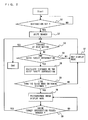
- FIG. 2 is a flowchart showing the operation of the navigation system according to the present invention.
- the route searching section 7 searches the route to the destination in accordance with vehicle position information obtained by the position determining section 1 (S2).
- the guide mode switching section 8 searches whether or not a guide target intersection exists on the route between the vehicle position and the destination (S4).
- the guide mode switching section 8 determines whether the distance between the vehicle position and the guide target intersection is greater or lower than a guide mode switching distance (for example, a distance of 300m to the guide target intersection) (S6).
- a guide mode switching distance for example, a distance of 300m to the guide target intersection
- NO in S6 a guide is performed in the map display mode
- YES in S6 a guide is switched to the photographed image display mode in which the photographed image obtained by the photographed image obtaining section 2 is displayed, and the guide object is overlaid on the photographed image (S8).
- a guide method in the photographed image display mode will be described later in detail.
- the guide mode switching section 8 determines that the vehicle has passed through the guide target intersection (YES in S9), and the guide mode switching section 8 again determines in which mode the guide is to be performed (S4 to S6).
- the guide mode is switched to the map display mode.
- the photographed image display mode is continuously applied. The route guide is performed until the vehicle arrives at the destination (YES in S3).
- the object display control section 9 calculates a camera view space in a three-dimensional map space (S11).
- the three-dimensional map is a map showing positional information based on a latitude, a longitude and an altitude.
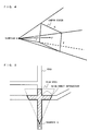
- the camera view space is calculated based on a method shown in FIG. 4 , for example.
- the view space is set at a position which is at an appropriate distance from the viewpoint E.
- a camera view space in a two-dimensional map space may be calculated by using the two-dimensional map which is obtained by eliminating height information from the three-dimensional map.
- the parameters for determining the imaging direction and the imaging range are not limited to those above mentioned. As long as the imaging direction and the imaging range can be determined, other parameters such as a view angle may be used for determination.
- the object display control section 9 then performs, in the three-dimensional map space, road detection processing for detecting a road existing in the camera view space and a location thereof (S12).
- road detection processing overlapping between the camera view space and a road area is calculated in the three-dimensional map space.
- FIG. 5 shows roads detected through the road detection processing.
- FIG. 5 is a diagram of the three-dimensional map space and the camera view space as viewed from an upper side thereof. As shown in FIG. 5 , the roads in the view space (a portion with slash lines) are detected through the road detection processing.
- the object display control section 9 locates the guide object at a location on a road, which corresponds to the guide route searched by the route searching section 7, among roads detected through the road detection processing (S13).
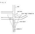
- FIG. 6 shows a location of the guide object.
- a shape of the guide object is not limited to an arrow figure as shown in FIG. 6 .
- a broken line figure which is obtained by removing a triangle from a front end of the arrow figure may be applicable.
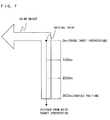
- the object display control section 9 assigns, to respective points on the guide object, respective distances to the guide target intersection (distance setting processing S14) .
- the guide target intersection is set as an original point, and the distances from the respective positions to the guide target intersection are calculated along the route.
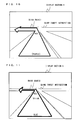
- FIG. 7 shows the guide object at a position 300m before the intersection, and distances to the guide target intersection, which range from 0 to 300m, are assigned to respective points in between the vehicle position and the guide target intersection.
- the position (original point) of the guide target intersection is not limited to a location indicated in FIG. 7 , but may be any location, for example, at a central part of a bending position of the arrow figure.
- the distances to the guide target intersection may be assigned to the positions on the guide object on a minimum necessary basis so as to determine the display mode of the guide object.
- the object display control section 9 then arranges a color of the guide object in accordance with the distance to the guide target intersection (color arrangement processing S15).
- color arrangement processing as shown in FIG. 8 , for example, a red color is arranged with respect to a position corresponding to the guide target intersection (the distance to the intersection: 0m), a blue color is arranged with respect to a position corresponding to the vehicle position (the distance to the intersection: 300m), and with respect to a section therebetween, a color is changed in a gradual manner in accordance with the distance to the guide target intersection. Accordingly, the color is gradually changed from blue to red, in a range between the vehicle position and the guide target intersection. As shown in FIG.
- a purple color is arranged, which is a halftone between red and blue.
- the red color may be arranged in the same manner as the original point. Alternatively, the color may be changed and displayed depending on whether the turn is made to the right or left.
- the object display control section 9 performs projection transformation (projection processing, S16) of the guide object by using the camera screen shown in FIG.4 as a projection plane.
- the display section 5 overlays the guide object having undergone the projection processing on the photographed image obtained by the photographed image obtaining section 2, and then displays a resultant thereof on the display screen (S17).
- the projection plane, onto which the guide object is projected in the projection processing, corresponds to the camera screen of the photographed image obtaining section 2, and thus the guide object is overlaid on the road (corresponding to the guide route) shown in the photographed image.
- a position of the guide object to be overlaid may be corrected by detecting a location of the road shot by the camera using a known image recognition technique such as white line detection and road edge detection.
- the photographed image mode is continuously applied until a photographed image display mode end condition (in which there is no guide target intersection on the route between the vehicle position and the destination, or in which the distance between the vehicle position and the guide target intersection is greater than the guide mode switching distance) is satisfied (YES in S18).
- FIG. 9 is an exemplary display screen displayed on the display section 5 at a location 300m before the intersection.
- the guide object shown in FIG. 9 is obtained by projecting the guide object shown in FIG. 8 onto the photographed image.
- the guide object is drawn in red at a portion thereof in the vicinity of the guide target intersection, and drawn in blue at a portion thereof in the vicinity of the vehicle position.
- the color to draw the guide object varies from blue to red in a gradual manner such that a color close to red is arranged to a portion closer to the guide target intersection.
- FIG. 10 a display screen showing a situation in which the vehicle further travels about 150m from a state shown in FIG. 9 , and reaches a location 150m before the intersection.
- the color of the guide object is determined based on the distance to the intersection. Therefore, as shown in FIG. 10 , at the portion in the vicinity of the guide target intersection, the guide object is drawn in red, in the same manner as in FIG. 9 , whereas at the portion in the vicinity of the vehicle position, the guide object is drawn in purple which indicates that the location is 150m before the intersection.
- the section between the vehicle position and the guide target intersection is drawn with a color varying from purple to red in a gradual manner such that a portion close to the guide target intersection is drawn in a color close to red. That is, at the location 150m before the intersection, only a range B of the guide object shown in FIG. 8 is drawn.
- the display color of the guide object is set in accordance with the distance between the arbitrary position on the route and the guide target intersection, whereby information indicative of a relative distance between a halfway point to the guide target intersection and the guide target intersection is also displayed. Accordingly, the driver is able to obtain a measure to grasp a sense of distance, and is also able to grasp intuitively and instantly the distance to the guide target intersection. Particularly, this effect becomes significant since, in the case were the display color of the guide object is set to vary in the gradual manner, as shown in the-above described example, the display color varies continuously in accordance with the distance to the guide target intersection, and consequently the display color becomes closer to the color assigned to a portion of the guide target intersection, the portion being in the vicinity of the guide target intersection.
- the guide object is overlaid on the position on the road (corresponding to the guide route) in the photographed image, whereby it is possible to intuitively grasp the distance to the guide target intersection on the photographed image on which the actual scene ahead of the vehicle is reflected as it is. Accordingly, it is possible to easily grasp the distance to the guide target intersection in the actual scene lying ahead of the windshield.
- an image is displayed by the display section 5 such that the vehicle travels on the guide object drawn on the road.
- the display changes as if the vehicle travels on the guide object.
- the color of the guide object in the vicinity of the vehicle becomes closer to red, and further approaches the portion drawn in red gradually. According to the display as above described, it is possible to intuitively grasp the distance to the intersection, and also possible to instantly grasp the distance to the guide target intersection regardless of where the vehicle travels.
- the guide object overlaid on the photographed image is processed through transparency processing so as to see the background through the guide object. Accordingly, it is possible to avoid a situation in which a scene ahead (e.g., vehicles traveling ahead) of the vehicle is covered by the guide object and cannot be seen.
- a scene ahead e.g., vehicles traveling ahead
- the red color (representing the guide target intersection) and the blue color (representing the vehicle position) are used as the reference colors, and to the section therebetween, colors between red and blue are assigned.
- the colors used as the reference are not limited to two.
- three colors, i.e., red, yellow, and blue are used as the reference colors, and the color of the portion of the guide object in the vicinity of the vehicle position may be changed from blue to yellow and then to red in a gradual manner as the vehicle approaches the intersection.
- the color set in the color arrangement processing may not necessarily be displayed in a gradual manner. For example, as shown in FIG. 12 , a distance interval between the guide target intersection and a position 100m before the intersection may be displayed in red, a distance interval ranging 100 to 200 m before the intersection may be displayed in yellow, and a distance interval ranging 200 to 300m before the intersection may be displayed in blue.
- FIG. 13 shows a display screen in the case where the density of the color is changed. As shown in FIG. 13 , an effect can be obtained in which an area of a deeper color approaches gradually, as the vehicle approaches the intersection.
- FIG. 14 shows a display screen in the case where the pattern of the guide object is changed in accordance with the distance to the guide target intersection.
- spacing of a pattern drawn on the guide object (horizontal lines) is set to become narrower, whereby an effect can be obtained, in which the density of the pattern on the object in the vicinity of the vehicle position becomes higher gradually as the vehicle approaches the guide target intersection. Accordingly, the driver can intuitively recognize the distance to the guide target intersection.
- a shape of the guide object may be changed. As shown in FIG. 15 , under the condition where a guide display is configured with a plurality of the guide objects, when the guide objects are arranged such that the object closer to the intersection is of a smaller size, the driver can intuitively recognize the distance to the intersection in the same manner as the case shown in FIG. 14 .
- any form may be applicable as long as the pattern and the shape of the guide object changes in accordance with the distance to the intersection.
- the case where any one of the display color, the pattern and the shape of the guide object is changed independently, as above described, may be replaced with a case where the display is performed by using any combination of these.
- a guide point is described as the guide target intersection.
- a stopover may be used as the guide point.
- the guide is switched to the photographed image display mode, and the color, the shape and the pattern of the guide object is changed in accordance with the distance to the destination, whereby the distance to the destination is displayed in a manner intuitively and easily recognizable by the driver.
- the photographed image displayed in the photographed image display mode is obtained from a camera which picks up an image ahead of the vehicle, but may be replaced with a video picture of the intersection which is stored in a HDD or obtained through communication.
- a case has been described where the guide object is overlaid on the photographed image display screen and the guide is performed.
- the present invention may be applied to a case where the guide object is overlaid on the guide route in the map display screen, and a color, a shape, a pattern of the guide object may be changed in accordance with the distance to the guide point.
- the driver can obtain the measure to grasp the sense of distance, the driver can intuitively and instantly grasp the distance to the guide point.
- the present invention is applied to a guide using a driver viewpoint map display in which a realistic scene, which is similar to a scene actually viewed by the driver, is reproduced. Further, the photographed image and the map image are displayed in a dual-screen display mode, and the present invention may be applied to each of the images.
- the camera is fixed to the vehicle, but, without limiting to this, may be fixed to a mobile unit such as a cellular phone.
- the navigation system according to the present invention exerts an effect of generating a display which enables an intuitive and instant grasp of the distance to the guide point, and is useful as a car navigation system installed in a vehicle, a navigation system for a mobile unit such as a cellular phone, and the like.
Abstract
Description
- The present invention relates to a navigation system, and more specifically relates to a navigation system generating a display which enables an intuitive and instant recognition of a distance to a guide point.
- In recent years, a navigation system has become widely available which displays a map of an area surrounding a vehicle position, calculates a route from the vehicle position to a destination, and performs a route guide in accordance with the calculated route. In the navigation system, a guide route is displayed on a map image so as to be distinguishable from other roads (by changing a color thereof, or by making a line of the route thick, for example). Alternatively, when the vehicle reaches a location at a predetermined distance from an approaching intersection on the guide route, a guide map of the intersection is displayed on the map image (for example, as an enlarged map of the intersection). Accordingly, a driver can understand a road to be traveled or a direction to proceed at the intersection.
- However, during driving, it is difficult for the driver to understand interrelation between the vehicle position displayed on the map and an actual vehicle position, and thus there have been posed a problem in that the driver makes a turn before the guide target intersection and a problem in that the driver passes through the intersection. Therefore, in order to show the driver a distance to the guide target intersection, a technique has been disclosed in which, in accordance with a distance between the vehicle position and the guide target intersection, a color of an arrow, which shows a direction to proceed at the intersection, is changed (Patent document 1).
Patent document 1: Japanese Laid-Open Patent Publication No.6-147909 - However, according to the conventional technique disclosed in above-described
Patent document 1, in accordance with the distance between the vehicle position and the guide target intersection, the color of the arrow is changed (for example, when the vehicle reaches alocation 300m before the intersection, the color of the arrow is changed to red, when the vehicle reaches alocation 200m before the intersection, the color of the arrow is changed to yellow, and when the vehicle reaches alocation 100m before the intersection, the color of the arrow is changed to blue). Accordingly, only a distance between the two points, i.e., the vehicle position and the guide target intersection, is shown, and the driver cannot obtain information on a distance between the guide target intersection and a halfway point between the vehicle position and the guide target intersection. Therefore, during driving at a location relatively far from the intersection (for example, at alocation 300m before the intersection), the driver cannot obtain a measure indicative of a distance between the location and a location proximity to the intersection (for example, alocation 100m before the intersection), and thus a problem is posed in that it is difficult to understand the distance to the intersection and also difficult to intuitively grasp when to prepare for making a turn. - Particularly in the case where the guide is performed by using a display which is close to an actual scene viewed by the driver, for example, by placing an arrow on a route in a photographed image, it tends to be difficult to understand the distance from a display in which the arrow is wholly drawn in a single color as disclosed in the conventional technique, and be also difficult to specify the intersection at which a turn is to be made.
- Further, in the conventional technique, the driver can only confirm a distance between the two points, i.e., the vehicle position and the guide target intersection, at a moment when the driver views a screen. Therefore, the driver cannot grasp positional information on a
location 100m before the intersection when the driver travels at a location further before the location (e.g., alocation 300m before the intersection) . The driver can finally grasp the positional information on thelocation 100m before the intersection when the vehicle actually reaches the position. Accordingly, in order to confirm a distance to the guide target intersection, the driver needs to check constantly a change in the color of the arrow, and consequently, the driver needs to focus on the screen or view the screen frequently. - Therefore, an object of the present invention is to provide a navigation system generating a display which enables an intuitive and instant recognition of a distance to a guide point.
- To achieve the above-described object, the present invention has the following aspects. A navigation system according to the present invention displays an object on a route between a vehicle position and a guide point, and comprises an object display control section for calculating a distance from an arbitrary position on the route to the guide point, the route being between the vehicle position and the guide point, and for setting a mode for displaying the object in accordance with the calculated distance. The guide point is a target point to be guided by the navigation system, and is typified by a guide target intersection (an intersection at which the a vehicle making a turn to the right or the left), a destination, and a stopover. The arbitrary position on the route includes the guide point and the vehicle position.
- As an example, the object display control section sets a display color of the object in accordance with the distance from the arbitraryposition on the route to the guide point. Accordingly, information on a distance between a halfway point to the guide point and the guide point is also displayed. Therefore, the driver can obtain a measure to grasp a sense of distance, and becomes able to grasp the distance to the guide point intuitively and instantly. Consequently, the driver no more needs to focus on a screen constantly, and thus is able to drive safely. Further, since the display color of the object is changed in accordance with the distance from the arbitrary point on the route to the guide point, the driver can grasp the distance to the guide point intuitively even though the driver does not clearly understand the relation between the display color and the distance.
- Preferably, the object display control section sets the display color of the object so as to be changed in a gradual manner in accordance with the distance from the arbitrary position on the route to the guide point. Accordingly, the display color is changed continuously in accordance with the distance to the guide point, and at a location closer to the intersection, the display color becomes closer to a color assigned to the guide point. Therefore, the distance to the guide point can be grasped more intuitively.
- Further, in the case where the display color is changed at predetermined distance interval in accordance with the distance to the guide point (for example, displayed in red at a distance interval between the guide target intersection to a
location 100m before the intersection, and displayed in blue at a distance interval ranging from 100m to 200m before the intersection), the whole of an arrow is displayed in a single display color in the vicinity of the intersection (100m or less before the intersection, in this case). However, the display color is set so as to be changed in a gradual manner, whereby the display color of the arrow at an arbitrary position can be changed in accordance with the distance from the arbitrary position on the route to the guide point, and thus the driver can constantly grasp the distance to the guide point. - The object display control section may set a pattern on the object in accordance with the distance from the arbitrary position on the route to the guide point. Preferably, the pattern on the object is set such that a density of the pattern becomes higher at a portion of the object closer to the guide point. Accordingly, an effect can be obtained in which the density of the pattern on the object becomes higher in the vicinity of the vehicle position as the vehicle gradually comes closer to the guide point. Accordingly, the driver can grasp the distance to the guide point intuitively.
- The object display control section may set a shape of the object in accordance with the distance from the arbitrary position on the route to the guide point. Preferably, the object display control section displays a plurality of the objects, and displays such that the closer to the guide point an object, among the objects, is located, the smaller a size of the object becomes. Accordingly, an effect can be obtained in which the size of the object in the vicinity of the vehicle position becomes gradually smaller as the vehicle comes closer to the guide point, and the driver can grasp the distance to the guide point intuitively.
- The object display control sectionmayoverlay the object on the photographed image. Accordingly, it is possible to grasp the distance to the guide point intuitively on the photographed image on which an actual scene ahead of the vehicle is reflected as it is, and also possible to easily grasp the distance to the guide point on the actual scene lying ahead of the windshield. Preferably, the object overlaid on the photographed image is processed through transparency processing so as to be seen transparently. Accordingly, it is possible to avoid a situation in which the scene ahead of the vehicle (such as vehicles traveling ahead) is covered and cannot be seen.
- In the navigation system according to the present invention, as is clear from the above-described solution to solve the problems, it is possible to generate a display which enables an intuitive and instant grasp of a distance to a guide point. Accordingly, the driver does not need to constantly focus on a screen, and is able to drive safely.
-
- [
FIG. 1] FIG. 1 is a diagram showing a configuration of a navigation system according to the present invention. - [
FIG. 2] FIG. 2 is a flowchart showing an operation of the navigation system according to the present invention. - [
FIG. 3] FIG. 3 shows a flowchart showing an operation of a photographed image display mode. - [
FIG. 4] FIG. 4 is a diagram showing a setting method of a camera view space in a three-dimensional map space. - [
FIG. 5] FIG. 5 is a diagram showing portions of roads detected through road detection processing. - [
FIG. 6] FIG. 6 is a diagram showing a location of a guide object in a three-dimensional map space. - [
FIG. 7] FIG. 7 is a diagram showing a distance setting method in distance setting processing. - [
FIG. 8] FIG. 8 is a diagram showing the guide object in the three-dimensional space in the case where a display color thereof is changed in a gradual manner in accordance with a distance to the guide target intersection (in the case where reference colors are two of red and blue). - [
FIG. 9] FIG. 9 is a diagram showing the guide object displayed on thedisplay section 5 in the case where the display color thereof is changed in the gradual manner in accordance with the distance (300m before the intersection) to the guide target intersection. - [
FIG. 10] FIG. 10 is a diagram showing the guide object displayed on thedisplay section 5 in the case where the display color thereof is changed in the gradual manner in accordance with the distance (150m before the intersection) to the guide target intersection. - [
FIG. 11] FIG. 11 is a diagram showing the guide object displayed on thedisplay section 5 in the case where the display color thereof is changed in the gradual manner in accordance with the distance to the guide target intersection (in the case where reference colors are three of red, yellow and blue). - [
FIG. 12] FIG. 12 is a diagram showing the guide object displayed on thedisplay section 5 in the case where the display color thereof is changed at a predetermined distance interval in accordance with the distance to the guide target intersection. - [
FIG. 13] FIG. 13 is a diagram showing the guide object in the case where a density of the display color is changed in accordance with the distance to the guide target intersection. - [
FIG. 14] FIG. 14 is a diagram showing the guide object displayed on thedisplay section 5 in the case where a pattern on the guide object is changed in accordance with the distance to the guide target intersection. - [
FIG. 15] FIG. 15 is a diagram showing the guide object displayed on thedisplay section 5 in the case where a shape of the guide object is changed in accordance with the distance to the guide target intersection. -
- 1
- position determining section
- 2
- photographed image obtaining section
- 3
- map DB
- 4
- input section
- 5
- display section
- 6
- control section
- 7
- route searching section
- 8
- guide mode switching section
- 9
- object display control section
- Hereinafter, a navigation system according to the present invention will be described with reference to diagrams. In each of the diagrams, component parts which are not related to the present invention are omitted.
FIG. 1 is a configuration diagram showing a general configuration of the navigation system according to the present invention. The navigation system is composed of aposition determining section 1, a photographedimage obtaining section 2, a map DB3, aninput section 4, adisplay section 5 and acontrol section 6. - The
position determining section 1 is a position determining sensor for obtaining information on a vehicle position, and is typified by a GPS (Global Positioning System) and a gyroscope fixed to a vehicle. The photographedimage obtaining section 2 is a camera for picking up an image forward of the vehicle. The image to be picked up may be either of a still image or a moving image.
The map DB3 is means for storing map information necessary for route guiding and searching, and is, for example, realized by an HDD and a DVD. - The
input section 4 is means for inputting, to the navigation system, information relating to a destination, and is composed of a remote control, a touch panel, a microphone for inputting sounds, and the like. Thedisplay section 5 displays a map image and a photographed image, and is typified by a LCD display, for example. - The
control section 6 is, for example, a CPU, and is composed of aroute searching section 7, a guidemode switching section 8 and an objectdisplay control section 9. With reference to the information relating to the destination inputted by theinput section 4, the vehicle position information obtained by theposition determining section 1, and the map DB3, theroute searching section 7 searches a route to the destination. With reference to the vehicle position information obtained by theposition determining section 1 and a guide route searched by theroute searching section 7, the guidemode switching section 8 calculates a distance to a guide target intersection which the vehicle is to pass through subsequently. When a distance to the guide target intersection is greater than a predetermined distance (a mode switching distance), a map image is displayed (a map display mode), whereas when the distance to the guide target intersection is equal to or less than the predetermined distance, the photographed image is displayed (a photographed image display mode). - In the photographed image display mode, the object
display control section 9 overlays a guide object on a position of a road in the photographed image so as to indicate a guide route. Accordingly, when the driver approaches the guide target intersection, the driver can recognize an intersection to be turned at while viewing the photographed image which reflects an actual scene ahead as it is. Further, the objectdisplay control section 9 calculates a distance from an arbitrary position on the route between the vehicle position and the guide target intersection to the guide target intersection, and sets the display color of the guide object in accordance with the calculated distance. An operation of the objectdisplay control section 9 will be described later in detail. - Next, an operation of the navigation system according to the present invention will be described with reference to the diagrams.
FIG. 2 is a flowchart showing the operation of the navigation system according to the present invention. When the destination is set to the navigation system (YES in S1) by using theinput section 4, theroute searching section 7 searches the route to the destination in accordance with vehicle position information obtained by the position determining section 1 (S2). When it is confirmed that the vehicle is yet to arrive at the destination (NO in S3), the guidemode switching section 8 searches whether or not a guide target intersection exists on the route between the vehicle position and the destination (S4). When the guide target intersection does not exist on the route between the vehicle position and the destination (NO in S4), a guide is performed in the map display mode in which the guide object is overlaid on the guide route in the map (S7). On the other hand, when the guide target intersection exists on the route between the vehicle position and the destination (YES in S4), a distance between the vehicle position and the guide target intersection which the vehicle is subsequently passes through is calculated (S5). Thereafter, the distance between the vehicle position and the guide target intersection is calculated on a regular basis. - Next, the guide
mode switching section 8 determines whether the distance between the vehicle position and the guide target intersection is greater or lower than a guide mode switching distance (for example, a distance of 300m to the guide target intersection) (S6). When the distance to the guide target intersection is greater than the guide mode switching distance (NO in S6), a guide is performed in the map display mode (S7). On the other hand, when the distance to the guide target intersection is equal to or lower than the guide mode switching distance (YES in S6), a guide is switched to the photographed image display mode in which the photographed image obtained by the photographedimage obtaining section 2 is displayed, and the guide object is overlaid on the photographed image (S8). A guide method in the photographed image display mode will be described later in detail. When the guidemode switching section 8 determines that the vehicle has passed through the guide target intersection (YES in S9), and the guidemode switching section 8 again determines in which mode the guide is to be performed (S4 to S6). When a guide target intersection does not exist on the route from the vehicle position to the destination, or when the distance between the vehicle position and the guide target intersection is greater than the guide mode switching distance, the guide mode is switched to the map display mode. On the other hand, when the distance between the vehicle position and the guide target intersection is equal to or lower than the guide mode switching distance, the photographed image display mode is continuously applied. The route guide is performed until the vehicle arrives at the destination (YES in S3). - Next, an operation in the photographed image display mode will be described with reference to a flowchart shown in
FIG. 3 . Based on a three-dimensional map stored in the map DB3, and parameters to determine an imaging direction and an imaging range of the photographedimage obtaining section 2, the parameters including a camera position, a camera angle (a horizontal angle and an elevation angle), a focal length and an image size, the objectdisplay control section 9 calculates a camera view space in a three-dimensional map space (S11). The three-dimensional map is a map showing positional information based on a latitude, a longitude and an altitude. The camera view space is calculated based on a method shown inFIG. 4 , for example. In the three-dimensional map space, a point (point F), which is positioned away from a camera position (viewpoint) E by a focal length f in a camera angle direction, is calculated, and a plain surface (a camera screen) having an x width and a y height, which corresponds to an image size, is placed at the point so as to be perpendicular to avector from the viewpoint E to the point F. A three-dimensional space, which is created with half-lines connecting between the viewpoint E and points at four corners of the camera screen, is then calculated. Although the three-dimensional space logically extents to infinity, the view space is set at a position which is at an appropriate distance from the viewpoint E. Instead of the three-dimensional map, a camera view space in a two-dimensional map space may be calculated by using the two-dimensional map which is obtained by eliminating height information from the three-dimensional map. Further, the parameters for determining the imaging direction and the imaging range are not limited to those above mentioned. As long as the imaging direction and the imaging range can be determined, other parameters such as a view angle may be used for determination. - The object
display control section 9 then performs, in the three-dimensional map space, road detection processing for detecting a road existing in the camera view space and a location thereof (S12). In the road detection processing, overlapping between the camera view space and a road area is calculated in the three-dimensional map space.FIG. 5 shows roads detected through the road detection processing.FIG. 5 is a diagram of the three-dimensional map space and the camera view space as viewed from an upper side thereof. As shown inFIG. 5 , the roads in the view space (a portion with slash lines) are detected through the road detection processing. - In the three-dimensional map space, the object
display control section 9 then locates the guide object at a location on a road, which corresponds to the guide route searched by theroute searching section 7, among roads detected through the road detection processing (S13).FIG. 6 shows a location of the guide object. A shape of the guide object is not limited to an arrow figure as shown inFIG. 6 . For example, a broken line figure which is obtained by removing a triangle from a front end of the arrow figure may be applicable. - The object
display control section 9 assigns, to respective points on the guide object, respective distances to the guide target intersection (distance setting processing S14) . Specifically, as shown inFIG. 7 , the guide target intersection is set as an original point, and the distances from the respective positions to the guide target intersection are calculated along the route.FIG. 7 shows the guide object at aposition 300m before the intersection, and distances to the guide target intersection, which range from 0 to 300m, are assigned to respective points in between the vehicle position and the guide target intersection. The position (original point) of the guide target intersection is not limited to a location indicated inFIG. 7 , but may be any location, for example, at a central part of a bending position of the arrow figure. Further, the distances to the guide target intersection may be assigned to the positions on the guide object on a minimum necessary basis so as to determine the display mode of the guide object. - Based on a result of the distance setting processing, the object
display control section 9 then arranges a color of the guide object in accordance with the distance to the guide target intersection (color arrangement processing S15). In the color arrangement processing, as shown inFIG. 8 , for example, a red color is arranged with respect to a position corresponding to the guide target intersection (the distance to the intersection: 0m), a blue color is arranged with respect to a position corresponding to the vehicle position (the distance to the intersection: 300m), and with respect to a section therebetween, a color is changed in a gradual manner in accordance with the distance to the guide target intersection. Accordingly, the color is gradually changed from blue to red, in a range between the vehicle position and the guide target intersection. As shown inFIG. 8 , for example, at an intermediate position between the vehicle position and the guide target intersection (a 150m point to the intersection), a purple color is arranged, which is a halftone between red and blue. With respect to a color of a portion of the guide object, the portion corresponding to a road taken after a turn at the guide target intersection (a portion indicated by range A inFIG. 8 ), the red color may be arranged in the same manner as the original point. Alternatively, the color may be changed and displayed depending on whether the turn is made to the right or left. - The object
display control section 9 performs projection transformation (projection processing, S16) of the guide object by using the camera screen shown inFIG.4 as a projection plane. Thedisplay section 5 overlays the guide object having undergone the projection processing on the photographed image obtained by the photographedimage obtaining section 2, and then displays a resultant thereof on the display screen (S17). The projection plane, onto which the guide object is projected in the projection processing, corresponds to the camera screen of the photographedimage obtaining section 2, and thus the guide object is overlaid on the road (corresponding to the guide route) shown in the photographed image. When the guide object is overlaid on the photographed image, a position of the guide object to be overlaid may be corrected by detecting a location of the road shot by the camera using a known image recognition technique such as white line detection and road edge detection. The photographed image mode is continuously applied until a photographed image display mode end condition (in which there is no guide target intersection on the route between the vehicle position and the destination, or in which the distance between the vehicle position and the guide target intersection is greater than the guide mode switching distance) is satisfied (YES in S18). -
FIG. 9 is an exemplary display screen displayed on thedisplay section 5 at alocation 300m before the intersection. The guide object shown inFIG. 9 is obtained by projecting the guide object shown inFIG. 8 onto the photographed image. As shown inFIG. 9 , the guide object is drawn in red at a portion thereof in the vicinity of the guide target intersection, and drawn in blue at a portion thereof in the vicinity of the vehicle position. As to a section between the vehicle position and the guide target intersection, the color to draw the guide object varies from blue to red in a gradual manner such that a color close to red is arranged to a portion closer to the guide target intersection. -
FIG. 10 a display screen showing a situation in which the vehicle further travels about 150m from a state shown inFIG. 9 , and reaches a location 150m before the intersection. The color of the guide object is determined based on the distance to the intersection. Therefore, as shown inFIG. 10 , at the portion in the vicinity of the guide target intersection, the guide object is drawn in red, in the same manner as inFIG. 9 , whereas at the portion in the vicinity of the vehicle position, the guide object is drawn in purple which indicates that the location is 150m before the intersection. The section between the vehicle position and the guide target intersection is drawn with a color varying from purple to red in a gradual manner such that a portion close to the guide target intersection is drawn in a color close to red. That is, at the location 150m before the intersection, only a range B of the guide object shown inFIG. 8 is drawn. - As above described, the display color of the guide object is set in accordance with the distance between the arbitrary position on the route and the guide target intersection, whereby information indicative of a relative distance between a halfway point to the guide target intersection and the guide target intersection is also displayed. Accordingly, the driver is able to obtain a measure to grasp a sense of distance, and is also able to grasp intuitively and instantly the distance to the guide target intersection. Particularly, this effect becomes significant since, in the case were the display color of the guide object is set to vary in the gradual manner, as shown in the-above described example, the display color varies continuously in accordance with the distance to the guide target intersection, and consequently the display color becomes closer to the color assigned to a portion of the guide target intersection, the portion being in the vicinity of the guide target intersection.
- Further, the guide object is overlaid on the position on the road (corresponding to the guide route) in the photographed image, whereby it is possible to intuitively grasp the distance to the guide target intersection on the photographed image on which the actual scene ahead of the vehicle is reflected as it is. Accordingly, it is possible to easily grasp the distance to the guide target intersection in the actual scene lying ahead of the windshield. In this case, an image is displayed by the
display section 5 such that the vehicle travels on the guide object drawn on the road. In the case of the above-described example, at thelocation 300m before the intersection, a portion of the guide object drawn in blue lies ahead of the vehicle, and a portion drawn in red is viewed far ahead. As the vehicle approaches the guide target intersection, the display changes as if the vehicle travels on the guide object. In the case of the above-described example, as the vehicle approaches the guide target intersection, the color of the guide object in the vicinity of the vehicle becomes closer to red, and further approaches the portion drawn in red gradually. According to the display as above described, it is possible to intuitively grasp the distance to the intersection, and also possible to instantly grasp the distance to the guide target intersection regardless of where the vehicle travels. - Preferably, the guide object overlaid on the photographed image is processed through transparency processing so as to see the background through the guide object. Accordingly, it is possible to avoid a situation in which a scene ahead (e.g., vehicles traveling ahead) of the vehicle is covered by the guide object and cannot be seen.
- In the case of the above-described example, in the color arrangement processing, only two colors, i.e., the red color (representing the guide target intersection) and the blue color (representing the vehicle position) are used as the reference colors, and to the section therebetween, colors between red and blue are assigned. However, the colors used as the reference are not limited to two. For example, as shown in
FIG. 11 , three colors, i.e., red, yellow, and blue are used as the reference colors, and the color of the portion of the guide object in the vicinity of the vehicle position may be changed from blue to yellow and then to red in a gradual manner as the vehicle approaches the intersection. - The color set in the color arrangement processing may not necessarily be displayed in a gradual manner. For example, as shown in
FIG. 12 , a distance interval between the guide target intersection and aposition 100m before the intersection may be displayed in red, a distance interval ranging 100 to 200 m before the intersection may be displayed in yellow, and a distance interval ranging 200 to 300m before the intersection may be displayed in blue. - In addition to the case where a color phase is changed as above described, parameters of the color such as lightness, saturation, a density and a contrast may be changed.
FIG. 13 shows a display screen in the case where the density of the color is changed. As shown inFIG. 13 , an effect can be obtained in which an area of a deeper color approaches gradually, as the vehicle approaches the intersection. - In addition to the color, a pattern of the guide object may be changed.
FIG. 14 shows a display screen in the case where the pattern of the guide object is changed in accordance with the distance to the guide target intersection. As shown inFIG. 14 , at a portion closer to the intersection, spacing of a pattern drawn on the guide object (horizontal lines) is set to become narrower, whereby an effect can be obtained, in which the density of the pattern on the object in the vicinity of the vehicle position becomes higher gradually as the vehicle approaches the guide target intersection. Accordingly, the driver can intuitively recognize the distance to the guide target intersection. - Further, a shape of the guide object may be changed. As shown in
FIG. 15 , under the condition where a guide display is configured with a plurality of the guide objects, when the guide objects are arranged such that the object closer to the intersection is of a smaller size, the driver can intuitively recognize the distance to the intersection in the same manner as the case shown inFIG. 14 . Without limiting to the above-described examples, any form may be applicable as long as the pattern and the shape of the guide object changes in accordance with the distance to the intersection. The case where any one of the display color, the pattern and the shape of the guide object is changed independently, as above described, may be replaced with a case where the display is performed by using any combination of these. - In the above-described example, a guide point is described as the guide target intersection. However, without limiting to this, the destination, a stopover may be used as the guide point. In this case, when the vehicle reaches a
location 300m before the destination, for example, in the same manner as the above-described case where the guide target intersection is used, the guide is switched to the photographed image display mode, and the color, the shape and the pattern of the guide object is changed in accordance with the distance to the destination, whereby the distance to the destination is displayed in a manner intuitively and easily recognizable by the driver. - The photographed image displayed in the photographed image display mode is obtained from a camera which picks up an image ahead of the vehicle, but may be replaced with a video picture of the intersection which is stored in a HDD or obtained through communication. In the above-described example, a case has been described where the guide object is overlaid on the photographed image display screen and the guide is performed. However, the present invention may be applied to a case where the guide object is overlaid on the guide route in the map display screen, and a color, a shape, a pattern of the guide object may be changed in accordance with the distance to the guide point. In this case, the driver can obtain the measure to grasp the sense of distance, the driver can intuitively and instantly grasp the distance to the guide point. This effect become significant particularly in the case where the present invention is applied to a guide using a driver viewpoint map display in which a realistic scene, which is similar to a scene actually viewed by the driver, is reproduced. Further, the photographed image and the map image are displayed in a dual-screen display mode, and the present invention may be applied to each of the images. In the above-described example, the camera is fixed to the vehicle, but, without limiting to this, may be fixed to a mobile unit such as a cellular phone.
- While the invention has been described in detail, the foregoing description is in all aspects illustrative and not restrictive. It is understood that numerous other modifications and variations can be devised without departing from the scope of the invention.
- The navigation system according to the present invention exerts an effect of generating a display which enables an intuitive and instant grasp of the distance to the guide point, and is useful as a car navigation system installed in a vehicle, a navigation system for a mobile unit such as a cellular phone, and the like.
Claims (9)
- A navigation system for displaying an object on a route between a vehicle position and a guide point, comprising
an object display control section for setting a mode for displaying the object at an arbitrary position on the route in accordance with a distance from the arbitrary point to the guide point. - The navigation system according to claim 1, wherein the object display control section sets a display color of the object in accordance with the distance from the arbitrary position on the route to the guide point.
- The navigation system according to claim 2, wherein the object display control section sets the display color of the object so as to be changed in a gradual manner in accordance with the distance from the arbitrary position on the route to the guide point.
- The navigation system according to claim 1, wherein the object display control section sets a pattern on the object in accordance with the distance from the arbitrary position on the route to the guide point.
- The navigation system according to claim 4, wherein the object display control section sets the pattern on the object such that a density of the pattern becomes higher at a portion of the object closer to the guide point.
- The navigation system according to claim 1, wherein the object display control section sets a shape of the object in accordance with the distance from the arbitrary position on the route to the guide point.
- The navigation system according to claim 6, wherein
the object display control section displays a plurality of the objects, and
displays such that the closer to the guide point an object, among the objects, is located, the smaller a size of the object becomes. - The navigation system according to claims 1 to 7, wherein the object display control section overlays the object on the photographed image.
- The navigation system according to claim 8, wherein the object display control section displays the object semi-transparently.
Applications Claiming Priority (2)
| Application Number | Priority Date | Filing Date | Title |
|---|---|---|---|
| JP2005310771A JP2007121001A (en) | 2005-10-26 | 2005-10-26 | Navigation device |
| PCT/JP2006/320669 WO2007049483A1 (en) | 2005-10-26 | 2006-10-17 | Navigation system |
Publications (3)
| Publication Number | Publication Date |
|---|---|
| EP1942314A1 true EP1942314A1 (en) | 2008-07-09 |
| EP1942314A4 EP1942314A4 (en) | 2010-08-25 |
| EP1942314B1 EP1942314B1 (en) | 2013-03-13 |
Family
ID=37967596
Family Applications (1)
| Application Number | Title | Priority Date | Filing Date |
|---|---|---|---|
| EP06811915A Active EP1942314B1 (en) | 2005-10-26 | 2006-10-17 | Navigation system |
Country Status (5)
| Country | Link |
|---|---|
| US (1) | US8036823B2 (en) |
| EP (1) | EP1942314B1 (en) |
| JP (1) | JP2007121001A (en) |
| CN (1) | CN101297177B (en) |
| WO (1) | WO2007049483A1 (en) |
Cited By (6)
| Publication number | Priority date | Publication date | Assignee | Title |
|---|---|---|---|---|
| WO2009149959A1 (en) * | 2008-06-13 | 2009-12-17 | Audi Ag | Method for combined output of an image and driving information and corresponding motor vehicle |
| WO2012066131A1 (en) * | 2010-11-19 | 2012-05-24 | Bayerische Motoren Werke Aktiengesellschaft | Method for outputting navigation instructions |
| DE102012215038A1 (en) | 2012-08-23 | 2014-05-28 | Bayerische Motoren Werke Aktiengesellschaft | Device for providing navigation information for driver of vehicle, displays numerical instructions of distance of determined display location to driving maneuver to driver of vehicle such that instructions are provided in certain location |
| DE102012216144A1 (en) * | 2012-09-12 | 2014-05-28 | Bayerische Motoren Werke Aktiengesellschaft | Contact analog display, in particular of a lane change |
| WO2015177271A3 (en) * | 2014-05-22 | 2016-01-07 | Bayerische Motoren Werke Aktiengesellschaft | Displaying maneuvering instructions along a route |
| WO2019189619A1 (en) * | 2018-03-29 | 2019-10-03 | Ricoh Company, Ltd. | Image control apparatus, display apparatus, movable body, and image control method |
Families Citing this family (49)
| Publication number | Priority date | Publication date | Assignee | Title |
|---|---|---|---|---|
| DE102006010478A1 (en) * | 2006-03-07 | 2007-09-13 | Robert Bosch Gmbh | Method and arrangement for displaying navigation instructions |
| JP4992634B2 (en) * | 2007-09-24 | 2012-08-08 | 株式会社デンソー | Road display device and program for road display device |
| JP5071033B2 (en) * | 2007-10-18 | 2012-11-14 | 日産自動車株式会社 | Route guidance device and route guidance method |
| JP4983552B2 (en) * | 2007-11-05 | 2012-07-25 | 日産自動車株式会社 | On-vehicle navigation device and route guidance method |
| US20100245561A1 (en) * | 2007-12-28 | 2010-09-30 | Yoshihisa Yamaguchi | Navigation device |
| CN101910792A (en) * | 2007-12-28 | 2010-12-08 | 三菱电机株式会社 | Navigation system |
| CN101910794B (en) * | 2008-01-31 | 2013-03-06 | 三菱电机株式会社 | Navigation device |
| JP4852062B2 (en) * | 2008-03-28 | 2012-01-11 | 株式会社東芝 | Monocular image display device and monocular image display method |
| JP5104589B2 (en) * | 2008-06-25 | 2012-12-19 | 株式会社Jvcケンウッド | GUIDANCE DISPLAY DEVICE, GUIDANCE DISPLAY METHOD, AND PROGRAM |
| JP5272843B2 (en) * | 2009-03-25 | 2013-08-28 | 株式会社Jvcケンウッド | Information display method, information display system, and portable terminal |
| JP5275963B2 (en) * | 2009-12-08 | 2013-08-28 | 株式会社東芝 | Display device, display method, and moving body |
| JP2011214936A (en) * | 2010-03-31 | 2011-10-27 | Denso Corp | Road information display device |
| WO2011148611A1 (en) | 2010-05-24 | 2011-12-01 | 三菱電機株式会社 | Navigation system |
| TWI465688B (en) * | 2010-06-07 | 2014-12-21 | Fih Hong Kong Ltd | Vehicle navigation device and method |
| US8730319B2 (en) * | 2010-07-09 | 2014-05-20 | Kabushiki Kaisha Toshiba | Display device, image data generating device, image data generating program, and display method |
| WO2012026406A1 (en) * | 2010-08-27 | 2012-03-01 | 京セラ株式会社 | Handheld electronic device and method for using handheld electronic device |
| CN102564437A (en) * | 2010-12-30 | 2012-07-11 | 上海博泰悦臻电子设备制造有限公司 | Complex intersection display method and complex intersection display system |
| US20120176525A1 (en) * | 2011-01-12 | 2012-07-12 | Qualcomm Incorporated | Non-map-based mobile interface |
| DE102011006347B4 (en) * | 2011-03-29 | 2023-02-09 | Bayerische Motoren Werke Aktiengesellschaft | Process for outputting graphical driving instructions |
| CN102788582A (en) * | 2011-05-19 | 2012-11-21 | 昆达电脑科技(昆山)有限公司 | Vehicle navigation method and vehicle navigation system |
| US9228835B2 (en) * | 2011-09-26 | 2016-01-05 | Ja Vad Gnss, Inc. | Visual stakeout |
| US8781170B2 (en) * | 2011-12-06 | 2014-07-15 | GM Global Technology Operations LLC | Vehicle ghosting on full windshield display |
| KR20130063605A (en) | 2011-12-07 | 2013-06-17 | 현대자동차주식회사 | A road guidance display method and system using geo-tagging picture |
| JP2013124957A (en) * | 2011-12-15 | 2013-06-24 | Car Mate Mfg Co Ltd | Navigation system using portable information terminal |
| JP5935636B2 (en) * | 2012-09-28 | 2016-06-15 | アイシン・エィ・ダブリュ株式会社 | Intersection guidance system, method and program |
| USD750663S1 (en) | 2013-03-12 | 2016-03-01 | Google Inc. | Display screen or a portion thereof with graphical user interface |
| US8676431B1 (en) | 2013-03-12 | 2014-03-18 | Google Inc. | User interface for displaying object-based indications in an autonomous driving system |
| USD754190S1 (en) * | 2013-03-13 | 2016-04-19 | Google Inc. | Display screen or portion thereof with graphical user interface |
| USD754189S1 (en) * | 2013-03-13 | 2016-04-19 | Google Inc. | Display screen or portion thereof with graphical user interface |
| CN104515529A (en) * | 2013-09-27 | 2015-04-15 | 高德软件有限公司 | Real-scenery navigation method and navigation equipment |
| JP6661883B2 (en) * | 2015-02-09 | 2020-03-11 | 株式会社デンソー | Vehicle display control device and vehicle display control method |
| JP6613616B2 (en) * | 2015-05-19 | 2019-12-04 | 日本精機株式会社 | Vehicle display device |
| CN105043407A (en) * | 2015-06-30 | 2015-11-11 | 长安马自达汽车有限公司 | Active driving display screen navigation guidance information updating optimizing method |
| JP6536853B2 (en) | 2015-07-27 | 2019-07-03 | 日産自動車株式会社 | Lane display device and lane display method |
| JP6623887B2 (en) * | 2016-03-29 | 2019-12-25 | アイシン・エィ・ダブリュ株式会社 | Route display system and route display program |
| JP6834685B2 (en) * | 2017-03-29 | 2021-02-24 | アイシン精機株式会社 | Vehicle guidance devices, methods and programs |
| CN108303972B (en) | 2017-10-31 | 2020-01-17 | 腾讯科技(深圳)有限公司 | Interaction method and device of mobile robot |
| JP6820561B2 (en) * | 2017-12-28 | 2021-01-27 | パナソニックIpマネジメント株式会社 | Image processing device, display device, navigation system, image processing method and program |
| DE102018203462A1 (en) * | 2018-03-07 | 2019-09-12 | Volkswagen Aktiengesellschaft | Method for calculating a display of additional information for a display on a display unit, device for carrying out the method and motor vehicle and computer program |
| JP7383888B2 (en) * | 2018-03-29 | 2023-11-21 | 株式会社リコー | Image control device, display device, moving object, image control method, and program |
| US11461976B2 (en) * | 2018-10-17 | 2022-10-04 | Mapbox, Inc. | Visualization transitions for augmented reality |
| CN109708653A (en) * | 2018-11-21 | 2019-05-03 | 斑马网络技术有限公司 | Crossing display methods, device, vehicle, storage medium and electronic equipment |
| CN110779541B (en) * | 2019-04-10 | 2021-11-23 | 北京嘀嘀无限科技发展有限公司 | Display method and system of steering arrow |
| WO2021039198A1 (en) * | 2019-08-23 | 2021-03-04 | 株式会社デンソー | Display control device and display control program |
| US11493357B2 (en) | 2019-09-02 | 2022-11-08 | Aisin Corporation | Superimposed image display device, superimposed image drawing method, and computer program |
| DE102020200047A1 (en) * | 2020-01-06 | 2021-07-08 | Volkswagen Aktiengesellschaft | Method and device for displaying virtual navigation elements |
| US20230063237A1 (en) * | 2020-02-19 | 2023-03-02 | Sony Group Corporation | Information processing apparatus, information processing method, and program |
| DE102020211298A1 (en) | 2020-09-09 | 2022-03-10 | Volkswagen Aktiengesellschaft | Method for representing a virtual element |
| JP2022086420A (en) * | 2020-11-30 | 2022-06-09 | 本田技研工業株式会社 | Display method, and system |
Citations (6)
| Publication number | Priority date | Publication date | Assignee | Title |
|---|---|---|---|---|
| WO1992000568A1 (en) * | 1990-06-25 | 1992-01-09 | Motorola, Inc. | Land vehicle navigation apparatus |
| DE4412859C1 (en) * | 1994-04-14 | 1994-11-10 | Vdo Schindling | Destination-guidance display |
| US6266613B1 (en) * | 1995-10-04 | 2001-07-24 | Aisin Aw Co., Ltd. | Navigation apparatus for a vehicle |
| DE10039687A1 (en) * | 2000-08-14 | 2002-02-28 | Volkswagen Ag | Vehicle-mounted navigation system displays fixed length base arrow along with variable length arrow whose length reduces as the vehicle approaches desired direction |
| EP1445583A1 (en) * | 2003-02-10 | 2004-08-11 | Lg Electronics Inc. | Navigation system with progression indication |
| US20050273252A1 (en) * | 2004-05-21 | 2005-12-08 | Axel Nix | Turn-by-turn navigation system with enhanced turn icon |
Family Cites Families (17)
| Publication number | Priority date | Publication date | Assignee | Title |
|---|---|---|---|---|
| DE4327780C2 (en) * | 1992-08-19 | 1998-12-17 | Aisin Aw Co | Vehicle navigation system and vehicle navigation method |
| JPH06147909A (en) | 1992-11-04 | 1994-05-27 | Honda Motor Co Ltd | Vehicle running guide device |
| JPH08190696A (en) * | 1994-11-07 | 1996-07-23 | Nippondenso Co Ltd | Route guide data display device |
| JP3307192B2 (en) * | 1995-10-04 | 2002-07-24 | アイシン・エィ・ダブリュ株式会社 | Vehicle navigation device |
| JP3408035B2 (en) * | 1995-11-17 | 2003-05-19 | 松下電器産業株式会社 | Road traffic information display method and road traffic information display device |
| JPH09243389A (en) * | 1996-03-08 | 1997-09-19 | Alpine Electron Inc | On-vehicle navigation system |
| JP2001074487A (en) * | 1999-07-02 | 2001-03-23 | Equos Research Co Ltd | Navigation device and route guiding method |
| JP2001074486A (en) | 1999-07-02 | 2001-03-23 | Equos Research Co Ltd | Navigation system |
| JP4250819B2 (en) | 1999-07-02 | 2009-04-08 | 株式会社エクォス・リサーチ | Navigation device |
| JP2003333586A (en) * | 2002-05-17 | 2003-11-21 | Pioneer Electronic Corp | Imaging apparatus, and control method for imaging apparatus |
| AU2003234907A1 (en) * | 2003-05-07 | 2004-11-26 | Seijiro Tomita | Method and apparatus for displaying image in car navigation system |
| JP4138574B2 (en) * | 2003-05-21 | 2008-08-27 | 株式会社日立製作所 | Car navigation system |
| JP2004363680A (en) * | 2003-06-02 | 2004-12-24 | Pioneer Electronic Corp | Display device and method |
| JP2005214857A (en) * | 2004-01-30 | 2005-08-11 | Sony Corp | Navigation system, and guide image preparation method |
| JP4423114B2 (en) * | 2004-06-02 | 2010-03-03 | アルパイン株式会社 | Navigation device and its intersection guidance method |
| JP4722433B2 (en) * | 2004-08-25 | 2011-07-13 | アルパイン株式会社 | Car navigation system |
| JP4562471B2 (en) * | 2004-09-14 | 2010-10-13 | アルパイン株式会社 | Navigation device and traveling direction guide method |
-
2005
- 2005-10-26 JP JP2005310771A patent/JP2007121001A/en active Pending
-
2006
- 2006-10-17 CN CN2006800399621A patent/CN101297177B/en active Active
- 2006-10-17 US US12/090,521 patent/US8036823B2/en active Active
- 2006-10-17 WO PCT/JP2006/320669 patent/WO2007049483A1/en active Application Filing
- 2006-10-17 EP EP06811915A patent/EP1942314B1/en active Active
Patent Citations (6)
| Publication number | Priority date | Publication date | Assignee | Title |
|---|---|---|---|---|
| WO1992000568A1 (en) * | 1990-06-25 | 1992-01-09 | Motorola, Inc. | Land vehicle navigation apparatus |
| DE4412859C1 (en) * | 1994-04-14 | 1994-11-10 | Vdo Schindling | Destination-guidance display |
| US6266613B1 (en) * | 1995-10-04 | 2001-07-24 | Aisin Aw Co., Ltd. | Navigation apparatus for a vehicle |
| DE10039687A1 (en) * | 2000-08-14 | 2002-02-28 | Volkswagen Ag | Vehicle-mounted navigation system displays fixed length base arrow along with variable length arrow whose length reduces as the vehicle approaches desired direction |
| EP1445583A1 (en) * | 2003-02-10 | 2004-08-11 | Lg Electronics Inc. | Navigation system with progression indication |
| US20050273252A1 (en) * | 2004-05-21 | 2005-12-08 | Axel Nix | Turn-by-turn navigation system with enhanced turn icon |
Non-Patent Citations (1)
| Title |
|---|
| See also references of WO2007049483A1 * |
Cited By (9)
| Publication number | Priority date | Publication date | Assignee | Title |
|---|---|---|---|---|
| WO2009149959A1 (en) * | 2008-06-13 | 2009-12-17 | Audi Ag | Method for combined output of an image and driving information and corresponding motor vehicle |
| WO2012066131A1 (en) * | 2010-11-19 | 2012-05-24 | Bayerische Motoren Werke Aktiengesellschaft | Method for outputting navigation instructions |
| US8831883B2 (en) | 2010-11-19 | 2014-09-09 | Bayerische Motoren Werke Aktiengesellschaft | Method for outputting navigation instructions |
| DE102012215038A1 (en) | 2012-08-23 | 2014-05-28 | Bayerische Motoren Werke Aktiengesellschaft | Device for providing navigation information for driver of vehicle, displays numerical instructions of distance of determined display location to driving maneuver to driver of vehicle such that instructions are provided in certain location |
| DE102012216144A1 (en) * | 2012-09-12 | 2014-05-28 | Bayerische Motoren Werke Aktiengesellschaft | Contact analog display, in particular of a lane change |
| US9733100B2 (en) | 2012-09-12 | 2017-08-15 | Bayerische Motoren Werke Aktiengesellschaft | Contact-analogue display, in particular of a lane change |
| WO2015177271A3 (en) * | 2014-05-22 | 2016-01-07 | Bayerische Motoren Werke Aktiengesellschaft | Displaying maneuvering instructions along a route |
| US11698266B2 (en) | 2014-05-22 | 2023-07-11 | Bayerische Motoren Werke Aktiengesellschaft | Displaying maneuvering instructions along a route |
| WO2019189619A1 (en) * | 2018-03-29 | 2019-10-03 | Ricoh Company, Ltd. | Image control apparatus, display apparatus, movable body, and image control method |
Also Published As
| Publication number | Publication date |
|---|---|
| EP1942314B1 (en) | 2013-03-13 |
| EP1942314A4 (en) | 2010-08-25 |
| CN101297177B (en) | 2011-06-08 |
| WO2007049483A1 (en) | 2007-05-03 |
| CN101297177A (en) | 2008-10-29 |
| US20100153000A1 (en) | 2010-06-17 |
| JP2007121001A (en) | 2007-05-17 |
| US8036823B2 (en) | 2011-10-11 |
Similar Documents
| Publication | Publication Date | Title |
|---|---|---|
| EP1942314B1 (en) | Navigation system | |
| JP4560090B2 (en) | Navigation device and navigation method | |
| JP4895313B2 (en) | Navigation apparatus and method | |
| JP5798392B2 (en) | Parking assistance device | |
| US9269007B2 (en) | In-vehicle display apparatus and program product | |
| JP5681569B2 (en) | Information processing system, server device, and in-vehicle device | |
| US20090262145A1 (en) | Information display device | |
| JP2009020089A (en) | System, method, and program for navigation | |
| JP5218607B2 (en) | Navigation device | |
| KR20180044993A (en) | Vehicle display device | |
| KR20180053396A (en) | Vehicle display device | |
| JP2008128827A (en) | Navigation device, navigation method, and program thereof | |
| US20230135641A1 (en) | Superimposed image display device | |
| EP2088571A2 (en) | Driving support device, driving support method and program | |
| JP2008145364A (en) | Route guiding device | |
| JP2016074410A (en) | Head-up display device and head-up display display method | |
| JP2005038225A (en) | Lane follow-up device | |
| WO2016056199A1 (en) | Head-up display device, and display method for head-up display | |
| JP2023012793A (en) | Superimposed image display device | |
| JP6065766B2 (en) | Information providing apparatus and information providing method | |
| JP2008002965A (en) | Navigation device and method therefor | |
| JP5071033B2 (en) | Route guidance device and route guidance method | |
| JP2019064422A (en) | Head-up display device | |
| JP7302389B2 (en) | Superimposed image display device and computer program | |
| JP2005104401A (en) | Parking support device and method |
Legal Events
| Date | Code | Title | Description |
|---|---|---|---|
| PUAI | Public reference made under article 153(3) epc to a published international application that has entered the european phase |
Free format text: ORIGINAL CODE: 0009012 |
|
| 17P | Request for examination filed |
Effective date: 20080411 |
|
| AK | Designated contracting states |
Kind code of ref document: A1 Designated state(s): DE FR GB |
|
| DAX | Request for extension of the european patent (deleted) | ||
| RAP1 | Party data changed (applicant data changed or rights of an application transferred) |
Owner name: PANASONIC CORPORATION |
|
| RBV | Designated contracting states (corrected) |
Designated state(s): DE FR GB |
|
| A4 | Supplementary search report drawn up and despatched |
Effective date: 20100723 |
|
| 17Q | First examination report despatched |
Effective date: 20110622 |
|
| GRAP | Despatch of communication of intention to grant a patent |
Free format text: ORIGINAL CODE: EPIDOSNIGR1 |
|
| RIC1 | Information provided on ipc code assigned before grant |
Ipc: G01C 21/36 20060101ALI20121211BHEP Ipc: G08G 1/0969 20060101ALI20121211BHEP Ipc: G09B 29/10 20060101ALI20121211BHEP Ipc: G01C 21/00 20060101AFI20121211BHEP |
|
| GRAS | Grant fee paid |
Free format text: ORIGINAL CODE: EPIDOSNIGR3 |
|
| GRAA | (expected) grant |
Free format text: ORIGINAL CODE: 0009210 |
|
| AK | Designated contracting states |
Kind code of ref document: B1 Designated state(s): DE FR GB |
|
| REG | Reference to a national code |
Ref country code: GB Ref legal event code: FG4D |
|
| REG | Reference to a national code |
Ref country code: DE Ref legal event code: R096 Ref document number: 602006035096 Country of ref document: DE Effective date: 20130508 |
|
| PLBE | No opposition filed within time limit |
Free format text: ORIGINAL CODE: 0009261 |
|
| STAA | Information on the status of an ep patent application or granted ep patent |
Free format text: STATUS: NO OPPOSITION FILED WITHIN TIME LIMIT |
|
| 26N | No opposition filed |
Effective date: 20131216 |
|
| REG | Reference to a national code |
Ref country code: DE Ref legal event code: R097 Ref document number: 602006035096 Country of ref document: DE Effective date: 20131216 |
|
| REG | Reference to a national code |
Ref country code: FR Ref legal event code: PLFP Year of fee payment: 10 |
|
| REG | Reference to a national code |
Ref country code: FR Ref legal event code: PLFP Year of fee payment: 11 |
|
| REG | Reference to a national code |
Ref country code: FR Ref legal event code: PLFP Year of fee payment: 12 |
|
| REG | Reference to a national code |
Ref country code: FR Ref legal event code: PLFP Year of fee payment: 13 |
|
| REG | Reference to a national code |
Ref country code: DE Ref legal event code: R084 Ref document number: 602006035096 Country of ref document: DE |
|
| PGFP | Annual fee paid to national office [announced via postgrant information from national office to epo] |
Ref country code: GB Payment date: 20231020 Year of fee payment: 18 |
|
| PGFP | Annual fee paid to national office [announced via postgrant information from national office to epo] |
Ref country code: FR Payment date: 20231023 Year of fee payment: 18 Ref country code: DE Payment date: 20231020 Year of fee payment: 18 |
|
| REG | Reference to a national code |
Ref country code: DE Ref legal event code: R081 Ref document number: 602006035096 Country of ref document: DE Owner name: PANASONIC AUTOMOTIVE SYSTEMS CO., LTD., YOKOHA, JP Free format text: FORMER OWNER: PANASONIC CORPORATION, KADOMA-SHI, OSAKA, JP |