JP7302389B2 - Superimposed image display device and computer program - Google Patents
Superimposed image display device and computer program Download PDFInfo
- Publication number
- JP7302389B2 JP7302389B2 JP2019159729A JP2019159729A JP7302389B2 JP 7302389 B2 JP7302389 B2 JP 7302389B2 JP 2019159729 A JP2019159729 A JP 2019159729A JP 2019159729 A JP2019159729 A JP 2019159729A JP 7302389 B2 JP7302389 B2 JP 7302389B2
- Authority
- JP
- Japan
- Prior art keywords
- vehicle
- guidance
- character string
- guide
- guide object
- Prior art date
- Legal status (The legal status is an assumption and is not a legal conclusion. Google has not performed a legal analysis and makes no representation as to the accuracy of the status listed.)
- Active
Links
Images


Description
本発明は、車両の走行支援を行う重畳画像表示装置及びコンピュータプログラムに関する。 The present invention relates to a superimposed image display device and a computer program for assisting driving of a vehicle.
従来より、車両の乗員に対して経路案内や障害物の警告等の車両の走行支援を行う為の各種情報を提供する情報提供手段として、様々な手段が用いられている。例えば、車両に設置された液晶ディスプレイによる表示や、スピーカから出力する音声等である。そして、近年、このような情報提供手段の一つとして、乗員の周辺環境(風景、実景)に重畳する画像を表示することによって、情報の提供を行う装置がある。例えば、ヘッドアップディスプレイ、ウインドウシールドディスプレイの他、液晶ディスプレイに表示した車両周辺の撮像画像に重畳して画像を表示する方法等が該当する。 2. Description of the Related Art Conventionally, various means have been used as information providing means for providing various types of information for assisting vehicle travel, such as route guidance and warnings of obstacles, to occupants of the vehicle. For example, it is the display by the liquid crystal display installed in the vehicle, the sound output from the speaker, or the like. In recent years, as one of such information providing means, there is a device that provides information by displaying an image superimposed on the surrounding environment (landscape, real scene) of the passenger. For example, a head-up display, a window shield display, or a method of displaying an image superimposed on a picked-up image of the surroundings of the vehicle displayed on a liquid crystal display.
ここで、重畳する画像の表示を行いた情報の提供を行う場合に、提供する情報の内容によっては画像を傾斜した状態で重畳表示する場合がある。例えば特開2011-149835号公報には、車両の右左折方向を示す矢印の画像を風景に重畳して表示することが開示されているが、特に案内する右左折方向が車両の進行方向に対して垂直に交差する方向ではなく傾斜(斜め右、或いは斜め左)している場合において、矢印の画像についても傾斜して表示することが開示されている。 Here, when information is provided by displaying an image to be superimposed, the image may be superimposed and displayed in an inclined state depending on the content of the information to be provided. For example, Japanese Patent Application Laid-Open No. 2011-149835 discloses that an image of an arrow indicating the right or left turn direction of a vehicle is superimposed on the landscape and displayed. It is disclosed that the image of the arrow is also displayed in an inclined manner when the arrow image is inclined (diagonally right or diagonally left) instead of intersecting perpendicularly with the arrow.
ここで、上記周辺環境に重畳する画像を表示することによって車両の乗員に案内を行う場合の1つの態様として、特に重畳する画像として文字列を表示することも考えられる。しかしながら、文字列については上記特許文献1に記載の技術のように、傾斜して表示することとすると、文字が変形したり文字幅が狭くなることによって、文字列の内容が認識し難くなる問題があった。 Here, displaying a character string as an image to be superimposed is also conceivable as one aspect of providing guidance to the occupants of the vehicle by displaying an image superimposed on the surrounding environment. However, if the character string is displayed at an angle as in the technique described in Patent Document 1, the characters will be deformed or the character width will become narrower, making it difficult to recognize the contents of the character string. was there.
本発明は前記従来における問題点を解消するためになされたものであり、車両周辺の風景に重畳して文字列を傾斜して表示する場合であっても、文字列の視認性を低下させることなく、文字列の内容を明確に乗員に認識させることを可能にした重畳画像表示装置及びコンピュータプログラムを提供することを目的とする。 SUMMARY OF THE INVENTION The present invention has been made in order to solve the above-mentioned conventional problems. It is an object of the present invention to provide a superimposed image display device and a computer program that enable an occupant to clearly recognize the contents of a character string.
前記目的を達成するため本発明に係る重畳画像表示装置は、車両に搭載され、前記車両の乗員へ情報を案内する案内オブジェクトを、前記車両周辺の風景に重畳して視認させる重畳画像表示装置であって、所定方向に沿って配列された文字列を含む前記案内オブジェクトを表示するオブジェクト表示手段を有し、前記オブジェクト表示手段は、前記所定方向と現在の車両の進行方向に対して垂直に交差する交差方向との差異が大きくなる程、前記文字列の幅を拡張して表示する。
尚、「風景」とは、実際に車両から視認される風景(実景)に加えて、風景を撮像した画像、風景を再現した画像等も含む。
In order to achieve the object, the superimposed image display device according to the present invention is a superimposed image display device that is mounted on a vehicle and allows a guide object that guides information to the occupants of the vehicle to be superimposed on the scenery around the vehicle and visually recognized. and object display means for displaying the guide object including a character string arranged along a predetermined direction, the object display means perpendicularly intersecting the predetermined direction and the current traveling direction of the vehicle. As the difference from the intersecting direction increases, the width of the character string is expanded and displayed.
Note that the “landscape” includes not only a landscape (actual landscape) that is actually visually recognized from a vehicle, but also an image of the landscape, an image of the landscape, and the like.
また、本発明に係るコンピュータプログラムは、車両の走行支援を行うプログラムである。具体的には、車両に搭載され、前記車両の乗員へ情報を案内する案内オブジェクトを、前記車両周辺の風景に重畳して視認させる重畳画像表示装置を、所定方向に沿って配列された文字列を含む前記案内オブジェクトを表示するオブジェクト表示手段として機能させる為のコンピュータプログラムである。また、前記オブジェクト表示手段は、前記所定方向と現在の車両の進行方向に対して垂直に交差する交差方向との差異が大きくなる程、前記文字列の幅を拡張して表示する。 Further, a computer program according to the present invention is a program for assisting driving of a vehicle. Specifically, a superimposed image display device, which is mounted on a vehicle and displays a guide object that guides information to the vehicle occupants, superimposed on the scenery around the vehicle, is arranged in a predetermined direction. is a computer program for functioning as object display means for displaying the guide object. Further, the object display means expands the width of the character string and displays it as the difference between the predetermined direction and the crossing direction perpendicular to the current traveling direction of the vehicle increases.
前記構成を有する本発明に係る重畳画像表示装置及びコンピュータプログラムによれば、車両周辺の風景に重畳して文字列を傾斜して表示する場合であっても、文字列の幅を拡張することによって、文字列の視認性が低下することを防止できる。その結果、文字列の内容を明確に乗員に認識させることが可能となる。 According to the superimposed image display device and the computer program according to the present invention having the above-described configuration, even when a character string is obliquely displayed while being superimposed on the scenery around the vehicle, the width of the character string is expanded. , it is possible to prevent the visibility of the character string from deteriorating. As a result, it is possible to make the passenger clearly recognize the content of the character string.
以下、本発明に係る重畳画像表示装置をナビゲーション装置に具体化した第1実施形態及び第2実施形態について図面を参照しつつ詳細に説明する。 DETAILED DESCRIPTION OF THE INVENTION A first embodiment and a second embodiment in which a superimposed image display device according to the present invention is embodied in a navigation device will be described in detail below with reference to the drawings.
[第1実施形態]
先ず、第1実施形態に係るナビゲーション装置1の概略構成について図1を用いて説明する。図1は第1実施形態に係るナビゲーション装置1を示したブロック図である。
[First embodiment]
First, a schematic configuration of a navigation device 1 according to the first embodiment will be described with reference to FIG. FIG. 1 is a block diagram showing a navigation device 1 according to the first embodiment.
図1に示すように第1実施形態に係るナビゲーション装置1は、ナビゲーション装置1が搭載された車両の現在位置を検出する現在位置検出部11と、各種のデータが記録されたデータ記録部12と、入力された情報に基づいて、各種の演算処理を行うナビゲーションECU13と、ユーザからの操作を受け付ける操作部14と、ユーザに対して進行方向前方を撮像した実景画像を表示する液晶ディスプレイ15と、経路案内に関する音声ガイダンスを出力するスピーカ16と、記憶媒体であるDVDを読み取るDVDドライブ17と、プローブセンタやVICS(登録商標:Vehicle Information and Communication System)センタ等の情報センタとの間で通信を行う通信モジュール18と、を有する。また、ナビゲーション装置1はCAN等の車載ネットワークを介して、ナビゲーション装置1の搭載された車両に対して設置されたフロントカメラ19や各種センサが接続されている。
As shown in FIG. 1, the navigation device 1 according to the first embodiment includes a current
以下に、ナビゲーション装置1が有する各構成要素について順に説明する。
現在位置検出部11は、GPS21、車速センサ22、ステアリングセンサ23、ジャイロセンサ24等からなり、現在の車両の位置、方位、車両の走行速度、現在時刻等を検出することが可能となっている。ここで、特に車速センサ22は、車両の移動距離や車速を検出する為のセンサであり、車両の駆動輪の回転に応じてパルスを発生させ、パルス信号をナビゲーションECU13に出力する。そして、ナビゲーションECU13は発生するパルスを計数することにより駆動輪の回転速度や移動距離を算出する。尚、上記4種類のセンサをナビゲーション装置1が全て備える必要はなく、これらの内の1又は複数種類のセンサのみをナビゲーション装置1が備える構成としても良い。
Each component of the navigation device 1 will be described in order below.
The current
また、データ記録部12は、外部記憶装置及び記録媒体としてのハードディスク(図示せず)と、ハードディスクに記録された地図情報DB31や所定のプログラム等を読み出すとともにハードディスクに所定のデータを書き込む為のドライバである記録ヘッド(図示せず)とを備えている。尚、データ記録部12をハードディスクの代わりにフラッシュメモリやメモリーカードやCDやDVD等の光ディスクにより構成しても良い。また、地図情報DB31は外部のサーバに格納させ、ナビゲーション装置1が通信により取得する構成としても良い。
The
ここで、地図情報DB31は、例えば、道路(リンク)に関するリンクデータ32、ノード点に関するノードデータ33、分岐点に関する分岐点データ34、施設等の地点に関する地点データ、地図を表示するための地図表示データ、経路を探索するための探索データ、地点を検索するための検索データ等が記憶された記憶手段である。
Here, the
また、リンクデータ32としては、道路を構成する各リンクに関してリンクの属する道路の幅員、勾(こう)配、カント、バンク、路面の状態、道路の車線数、車線数の減少する箇所、幅員の狭くなる箇所、踏切り等を表すデータが、コーナに関して、曲率半径、交差点、T字路、コーナの入口及び出口等を表すデータが、道路属性に関して、降坂路、登坂路等を表すデータが、道路種別に関して、高速道路と一般道(国道、県道、細街路等)を表すデータがそれぞれ記録される。
The
また、ノードデータ33としては、実際の道路の分岐点(交差点、T字路等も含む)や各道路に曲率半径等に応じて所定の距離毎に設定されたノード点の座標(位置)、ノードが交差点に対応するノードであるか等を表すノード属性、ノードに接続するリンクのリンク番号のリストである接続リンク番号リスト、ノードにリンクを介して隣接するノードのノード番号のリストである隣接ノード番号リスト、各ノード点の高さ(高度)等に関するデータ等が記録される。
The
また、分岐点データ34としては、分岐点の交差点名称、分岐点を形成するノードを特定する該当ノード情報、分岐点に接続されるリンクを特定する接続リンク情報、分岐点に接続されるリンクに対応する方面名称、分岐点の形状を特定する情報等が記憶される。また、分岐点での右左折案内を行う場合に目印となり得る構造物についても記憶される。
The
一方、ナビゲーションECU(エレクトロニック・コントロール・ユニット)13は、ナビゲーション装置1の全体の制御を行う電子制御ユニットであり、演算装置及び制御装置としてのCPU41、並びにCPU41が各種の演算処理を行うにあたってワーキングメモリとして使用されるとともに、経路が探索されたときの経路データ等が記憶されるRAM42、制御用のプログラムのほか、後述の走行支援処理プログラム(図2)等が記録されたROM43、ROM43から読み出したプログラムを記憶するフラッシュメモリ44等の内部記憶装置を備えている。尚、ナビゲーションECU13は、処理アルゴリズムとしての各種手段を有する。例えば、オブジェクト表示手段は、所定方向に沿って配列された文字列を含む案内オブジェクトを表示する。
On the other hand, a navigation ECU (electronic control unit) 13 is an electronic control unit that controls the entire navigation device 1, and includes a
操作部14は、走行開始地点としての出発地及び走行終了地点としての目的地を入力する際等に操作され、各種のキー、ボタン等の複数の操作スイッチ(図示せず)を有する。そして、ナビゲーションECU13は、各スイッチの押下等により出力されるスイッチ信号に基づき、対応する各種の動作を実行すべく制御を行う。尚、操作部14は液晶ディスプレイ15の前面に設けたタッチパネルを有する構成としても良い。また、マイクと音声認識装置を有する構成としても良い。
The
また、液晶ディスプレイ15には、道路を含む地図画像、交通情報、操作案内、操作メニュー、キーの案内、出発地から目的地までの案内経路、案内経路に沿った案内情報、ニュース、天気予報、時刻、メール、テレビ番組等が表示される。また、特に第1実施形態では、通常の走行時において液晶ディスプレイ15にはフロントカメラ19で撮像した撮像画像、即ち現時点の車両周辺(特に車両前方)の風景(実景画像)を表示し、更に必要に応じて風景に対して案内オブジェクトを重畳させて表示する。
The
ここで、風景に重畳して表示される案内オブジェクトとしては、車両に関する情報や乗員の運転の支援の為に用いられる各種情報がある。例えば乗員に対して警告対象となる対象物(他車両、歩行者、案内標識)に対する警告、ナビゲーション装置1で設定された案内経路や案内経路に基づく案内情報(右左折方向を示す矢印、案内分岐点の目印を示すアイコン、案内分岐点までの距離等)、路面に表示する警告(追突注意、制限速度等)、車両が走行する車線の区画線、現在車速、シフト位置、エネルギ残量、広告画像、施設情報、案内標識、地図画像、交通情報、ニュース、天気予報、時刻、接続されたスマートフォンの画面等がある。尚、以下に説明する第1実施形態では案内オブジェクトは、車両の進行方向前方にある案内分岐点における案内を行う為の案内情報とし、より具体的には案内経路に沿った案内分岐点の退出方向を示す矢印等とする。 Here, the guide object superimposed on the scenery and displayed includes information about the vehicle and various kinds of information used for assisting the driver in driving. For example, warnings to objects (other vehicles, pedestrians, guide signs) to be warned to passengers, guidance routes set in the navigation device 1, and guidance information based on the guidance routes (arrows indicating right and left turn directions, guidance branching directions, etc.) icon indicating a point mark, distance to a guidance junction, etc.), warnings displayed on the road surface (caution for rear-end collision, speed limit, etc.), lane markings in which the vehicle is traveling, current vehicle speed, shift position, remaining energy level, advertisement Images, facility information, guide signs, map images, traffic information, news, weather forecasts, times, screens of connected smartphones, etc. In the first embodiment described below, the guidance object is guidance information for providing guidance at a guidance junction located in front of the vehicle in the direction of travel. Use an arrow or the like to indicate the direction.
また、スピーカ16は、ナビゲーションECU13からの指示に基づいて案内経路に沿った走行を案内する音声ガイダンスや、交通情報の案内を出力する。
In addition, the
また、DVDドライブ17は、DVDやCD等の記録媒体に記録されたデータを読み取り可能なドライブである。そして、読み取ったデータに基づいて音楽や映像の再生、地図情報DB31の更新等が行われる。尚、DVDドライブ17に替えてメモリーカードを読み書きする為のカードスロットを設けても良い。
Also, the
また、通信モジュール18は、交通情報センタ、例えば、VICSセンタやプローブセンタ等から送信された渋滞情報、規制情報、交通事故情報等の各情報から成る交通情報を受信する為の通信装置であり、例えば携帯電話機やDCMが該当する。
In addition, the
また、フロントカメラ19は、例えばCCD等の固体撮像素子を用いたカメラを有する撮像装置であり、光軸方向を車両の進行方向前方に向けて設置される。そして、フロントカメラ19により撮像された撮像画像は、前述したように車両周辺(特に車両前方)の風景(実景画像)として液晶ディスプレイ15に対して表示される。
The
続いて、前記構成を有するナビゲーション装置1においてナビゲーションECU13が実行する走行支援処理プログラムについて図2に基づき説明する。図2は第1実施形態に係る走行支援処理プログラムのフローチャートである。ここで、走行支援処理プログラムは車両のACC電源(accessory power supply)がONされた後に実行され、液晶ディスプレイ15に表示された車両周辺の風景に重畳した案内オブジェクトを視認させることによって、車両の走行支援を行うプログラムである。尚、以下の図2、図4及び図9にフローチャートで示されるプログラムは、ナビゲーション装置1が備えているRAM42やROM43に記憶されており、CPU41により実行される。
Next, a driving support processing program executed by the
以下の説明では案内オブジェクトを用いた車両の走行支援として、ナビゲーション装置1で設定された案内経路に沿った車両の走行案内を行う例について説明する。また、表示対象となる案内オブジェクトは、車両の進行方向前方にある案内分岐点における案内を行う為の案内情報とし、特に案内分岐点の退出方向と交差点名称を示す矢印及び案内分岐点の目印を示すアイコンを案内オブジェクトとして表示する場合の処理を例に挙げて説明する。但し、ナビゲーション装置1では案内オブジェクトを用いて上記走行支援以外の案内や情報提供を行うことも可能である。また、表示対象となる案内オブジェクトは、上記矢印やアイコン以外の情報とすることも可能である。例えば、案内オブジェクトとして乗員に対して警告対象となる対象物(他車両、歩行者、案内標識)に対する警告、路面に表示する警告(追突注意、制限速度等)、車両が走行する車線の区画線、現在車速、シフト位置、エネルギ残量、広告画像、施設情報、案内標識、地図画像、交通情報、ニュース、天気予報、時刻、接続されたスマートフォンの画面等を表示することも可能である。 In the following description, an example of performing vehicle travel guidance along a guidance route set by the navigation device 1 as vehicle travel assistance using a guide object will be described. The guidance objects to be displayed are guidance information for providing guidance at guidance junctions in the forward direction of the vehicle.In particular, an arrow indicating the exit direction of the guidance junction and the name of the intersection, and a guide junction marker. A description will be given by taking as an example the processing in the case of displaying the icon shown as a guide object. However, the navigation device 1 can also provide guidance and information other than the above-described driving assistance using the guidance object. Also, the guide object to be displayed can be information other than the arrows and icons. For example, as a guide object, there are warnings for objects to be warned to passengers (other vehicles, pedestrians, guide signs), warnings displayed on the road surface (caution for rear-end collisions, speed limits, etc.), and lane division lines in which the vehicle is traveling. , current vehicle speed, shift position, remaining energy, advertisement image, facility information, guide signs, map image, traffic information, news, weather forecast, time, screen of connected smartphone, etc. can also be displayed.
先ず、走行支援処理プログラムでは、ステップ(以下、Sと略記する)1においてCPU41は、車両の現在位置を現在位置検出部11の検出結果や地図情報に基づいて特定する。尚、車両の現在位置を特定する際には、車両の現在位置を地図情報にマッチングさせるマップマッチング処理についても行う。その後、ナビゲーション装置1で設定されている案内経路を読み出し、特定された車両の現在位置から案内経路に沿った次の案内分岐点までの距離を算出する。尚、案内分岐点とは、ナビゲーション装置1に設定されている案内経路に従ってナビゲーション装置1が走行の案内を行う際に、右左折指示等の案内を行う対象となる分岐点(交差点)である。
First, in the driving support processing program, in step (hereinafter abbreviated as S) 1, the
次に、S2においてCPU41は、前記S1で算出された次の案内分岐点までの距離が、所定の案内開始距離以下か否かを判定する。尚、案内開始距離は車両が走行する道路の道路種別によって決定され、例えば高速道路は1km、一般道は高速道路よりも短い300mとする。
Next, in S2, the
そして、前記S1で算出された次の案内分岐点までの距離が案内開始距離以下であると判定された場合(S2:YES)には、S3へと移行する。それに対して、前記S1で算出された次の案内分岐点までの距離が案内開始距離以下でないと判定された場合(S2:NO)には、S1へと戻る。 Then, when it is determined that the distance to the next guidance branch point calculated in S1 is equal to or less than the guidance start distance (S2: YES), the process proceeds to S3. On the other hand, if it is determined that the distance to the next guidance branch point calculated in S1 is not equal to or less than the guidance start distance (S2: NO), the process returns to S1.
S3においてCPU41は、案内オブジェクトによって案内対象とする地点、即ち案内オブジェクトを重畳(配置)させるべき地点(以下、案内点という)の座標を取得する。尚、第1実施形態では案内オブジェクトを用いて案内分岐点の右左折案内を行うので、案内点としては案内分岐点が該当し、従って案内点の座標は案内分岐点の座標Xに相当する。また、特に目印を用いた案内分岐点の右左折案内を行う場合には、目印に対しても案内オブジェクトを重畳させるので案内分岐点周辺にある目印(施設、構造物など)についても案内点に該当し、案内点の座標には案内分岐点周辺にある目印の座標Yについても含む。尚、案内分岐点の座標Xや案内分岐点周辺にある目印の座標Yはナビゲーション装置1が有する地図情報から特定することとするが、フロントカメラ19で撮像した画像に対して画像認識処理を行うことにより特定しても良い。
In S3, the
次に、S4においてCPU41は、後述の案内オブジェクト表示位置決定処理(図4)を行う。案内オブジェクト表示位置決定処理は、車両の現在位置や前記S3で取得された案内点の座標に基づいて、液晶ディスプレイ15に対して表示する案内オブジェクトの形状及び案内オブジェクトを表示する位置(範囲)を具体的に決定する処理である。尚、前記S4で決定される案内オブジェクトの形状及び案内オブジェクトを表示する位置は、例えば風景内の案内点に案内オブジェクトを重畳して乗員に視認させる為の条件となる。但し、後述のように車両の現在位置や案内オブジェクトの種類によっては風景内の案内点以外に案内オブジェクトを重畳して視認させる場合もある。
Next, in S4, the
続いて、S5においてCPU41は、液晶ディスプレイ15に対して制御信号を送信し、液晶ディスプレイ15に対して前記S4で決定された形状の案内オブジェクトの画像を、前記S4で決定された位置(範囲)に対して表示する。尚、液晶ディスプレイ15には予めフロントカメラ19で撮像した撮像画像、即ち現時点の車両周辺(特に車両前方)の風景(実景画像)が表示されている。その結果、車両の乗員に風景に重畳された案内オブジェクトを視認させることが可能となる。
Subsequently, in S5, the
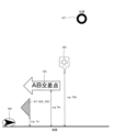
図3は前記S5において液晶ディスプレイ15に表示される走行案内画面51の一例を示した図である。図3に示すように液晶ディスプレイ15には、フロントカメラ19により撮像された現時点の車両前方の風景52が表示される。そして、車両前方の風景52に重畳して案内オブジェクトの画像53~55が表示される。
FIG. 3 is a diagram showing an example of the
ここで、第1実施形態では案内に用いられる案内オブジェクトとして複数種類の案内オブジェクトが存在し、案内の内容や現在の状況に応じて選択された一又は複数種類の案内オブジェクトが表示される。また、複数種類の案内オブジェクトが同時に表示対象となる場合がある。例えば図3に示す例では、案内分岐点の退出方向を示す3つの矢印からなる第1の案内オブジェクトの画像53と、案内分岐点の退出方向及び交差点名称を示す矢印からなる第2の案内オブジェクトの画像54と、案内分岐点の目印を示すアイコンからなる第3の案内オブジェクトの画像55とが同時に表示される。尚、各案内オブジェクトの画像53~55については、表示を開始するタイミングや表示を終了するタイミングについてはそれぞれ異なるタイミングとしても良い。また、案内オブジェクトの画像53~55は、風景52内にある案内点(即ち案内分岐点や案内分岐点の目印となる施設)に重畳して表示される。更に、特に第1の案内オブジェクトの画像53については仮想的に設定された光源によって下方の路面に生じる影の画像56についても表示される。
Here, in the first embodiment, there are a plurality of types of guidance objects as guidance objects used for guidance, and one or a plurality of types of guidance objects selected according to the content of guidance and the current situation are displayed. In addition, there are cases where multiple types of guide objects are to be displayed at the same time. For example, in the example shown in FIG. 3, a first
また、第1の案内オブジェクトの影の画像56については、影を重畳する対象となるエリアの明るさに応じた色相又は明度で表示するのが望ましい。具体的には、先ずフロントカメラ19で撮像した画像に対して画像処理を行ったり、照度センサを用いることによって影を重畳する対象となるエリアの明るさを取得する。そして、例えば晴天時の昼間のように影を重畳する対象となるエリアが明るい状況にある場合には、影をより周囲とはっきり識別できる色相と明度で表示する。一方で、曇りや夜間などの影を重畳する対象となるエリアが暗い状況にある場合には、影を周囲と識別可能な程度の色相と明度で表示する。また、夜間などの影が生じ得ない状況では影を表示しないようにしても良い。尚、案内オブジェクトの影の詳細については後述する。
Moreover, it is desirable to display the
従って、走行案内画面51を車両の乗員が視認した場合に、右左折対象となる案内分岐点の位置や、案内交差点における退出方向を正確に把握できる。特に第1の案内オブジェクトの矢印については影の画像56についても表示することによって、第1案内オブジェクトまでの距離、即ち案内分岐点までの距離が把握しやすくなる。
Therefore, when the vehicle occupant visually recognizes the
また、案内オブジェクトとしては上述した車両の案内分岐点の退出方向や交差点名称を示す矢印、案内分岐点の目印のアイコン以外に、案内交差点までの距離を示す画像についても風景に重畳して表示するようにしても良い。案内交差点までの距離を示す画像を重畳する位置は、例えば車両の前方直近とし、車両から案内分岐点までの距離が所定距離区間内(例えば300mから150m)にある間において表示する。 In addition to the above-mentioned arrow indicating the exit direction of the guidance branch point and the name of the intersection, and the icon indicating the guide branch point, an image indicating the distance to the guidance intersection is superimposed on the scenery and displayed as the guidance object. You can do it. The position where the image indicating the distance to the guidance intersection is superimposed is, for example, immediately in front of the vehicle, and is displayed while the distance from the vehicle to the guidance junction is within a predetermined distance section (eg, 300m to 150m).
その後、S6においてCPU41は、前記S1と同様に車両の現在位置から案内経路に沿った次の案内分岐点までの距離を算出し、算出された次の案内分岐点までの距離が、所定の案内終了距離以下か否かを判定する。尚、案内終了距離は車両が走行する道路の道路種別によって決定され、例えば高速道路は30m、一般道は高速道路よりも短い10mとする。
Thereafter, in S6, the
そして、次の案内分岐点までの距離が案内終了距離以下であると判定された場合(S6:YES)には、S7へと移行する。それに対して、次の案内分岐点までの距離が案内終了距離以下でないと判定された場合(S6:NO)にはS4へと戻り、案内オブジェクトの表示を継続して行う。 Then, when it is determined that the distance to the next guidance branch point is equal to or less than the guidance end distance (S6: YES), the process proceeds to S7. On the other hand, if it is determined that the distance to the next guidance branch point is not equal to or less than the guidance end distance (S6: NO), the process returns to S4 to continue displaying the guidance object.
続いて、S7においてCPU41は、液晶ディスプレイ15に対して制御信号を送信し、液晶ディスプレイ15に対して表示されている案内オブジェクトの画像(影の画像も含む)の透過率を案内分岐点までの距離に応じで段階的に上昇させる。具体的には、車両が案内分岐点に到達するタイミングで透過率が100%となるように透過率を上昇させる。尚、案内オブジェクトの画像の背後に隠れている風景についても車両の乗員が把握できるように、案内オブジェクトの画像は表示開始時点において透過率が0%ではなく例えば20%に設定されている。従って、案内オブジェクトの画像は、車両から案内分岐点までの距離が案内終了距離以下となるまでは透過率が20%で表示され、その後は案内分岐点に近づくにつれて20%→30%→40%→・・・と段階的に透過率が上昇し、最終的に車両が案内分岐点に到達するタイミングで透過率が100%となる。
Subsequently, in S7, the
その後、S8においてCPU41は、車両が案内分岐点を通過したか否かを判定する。例えば現在位置検出部11で検出された車両の現在位置と地図情報に基づいて判定される。
After that, in S8, the
そして、車両が案内分岐点を通過したと判定された場合(S8:YES)には、液晶ディスプレイ15に対して制御信号を送信し、液晶ディスプレイ15に表示されていた案内オブジェクトを非表示とする(S9)。尚、フロントカメラ19で撮像した撮像画像、即ち現時点の車両周辺(特に車両前方)の風景(実景画像)については継続して表示される。但し、風景の画像についても非表示とし、液晶ディスプレイ15の表示画面を地図画像の表示などに切り替えても良い。
When it is determined that the vehicle has passed through the guidance junction (S8: YES), a control signal is transmitted to the
一方、車両が案内分岐点を通過していないと判定された場合(S8:NO)にはS4へと戻り、案内オブジェクトの表示を継続して行う。 On the other hand, if it is determined that the vehicle has not passed through the guidance junction (S8: NO), the process returns to S4 to continue displaying the guidance object.
次に、前記S4において実行される案内オブジェクト表示位置決定処理のサブ処理について図4に基づき説明する。図4は案内オブジェクト表示位置決定処理のサブ処理プログラムのフローチャートである。 Next, sub-processing of the guidance object display position determination processing executed in S4 will be described with reference to FIG. FIG. 4 is a flow chart of a sub-processing program of guidance object display position determination processing.
先ず、S11においてCPU41は、表示対象とする案内オブジェクトの種類を決定する。ここで、第1実施形態では案内に用いられる案内オブジェクトとして複数種類の案内オブジェクトが存在し、案内の内容や現在の状況に応じて選択された一又は複数種類の案内オブジェクトが表示される。以下の説明では下記の(1)~(3)の3種類の案内オブジェクトから表示対象とする案内オブジェクトを決定する例について説明する。但し、下記の(1)~(3)以外の案内オブジェクト(例えば案内分岐点までの距離)を表示対象に含めることも可能である。
(1)『第1の案内オブジェクト』・・・案内分岐点の退出方向を示す3つの矢印
(2)『第2の案内オブジェクト』・・・案内分岐点の退出方向及び交差点名称を示す矢印
(3)『第3の案内オブジェクト』・・・案内分岐点の目印を示すアイコン
First, in S11, the
(1) "First guide object" --- Three arrows indicating the exit direction of the guidance junction (2) "Second guide object" ---- Arrows indicating the exit direction of the guidance junction and the name of the intersection ( 3) "Third guide object" --- An icon that indicates a guide branch point
そして、前記S11でCPU41は、車両の現在位置から案内分岐点までの距離と、案内分岐点に案内の目印となる施設や構造物が存在するか否かに基づいて、表示対象とする案内オブジェクトを決定する。尚、案内分岐点に案内の目印となる施設や構造物が存在するか否かを特定する情報は、地図情報の分岐点データ34に含まれている。以下に車両が一般道を走行する場合における決定方法の一例について図5を用いて説明する。
(A)案内分岐点の手前側150m以内に他の分岐点が無い場合
案内分岐点までの距離が300m以下であって且つ150m以下にない場合には、『第2の案内オブジェクト』のみを表示対象とする。
案内分岐点までの距離が150m以下である場合には、『第1の案内オブジェクト』と『第2の案内オブジェクト』を表示対象とする。更に、案内分岐点において案内の目印となる施設や構造物が存在する場合には『第3の案内オブジェクト』についても表示対象とする。
(B)案内分岐点の手前側150m以内に他の分岐点がある場合
案内分岐点までの距離が300m以下であって且つ他の分岐点に到達する前には、『第2の案内オブジェクト』のみを表示対象とする。
他の分岐点に到達した後は、『第1の案内オブジェクト』と『第2の案内オブジェクト』を表示対象とする。更に、案内分岐点において案内の目印となる施設や構造物が存在する場合には『第3の案内オブジェクト』についても表示対象とする。
In S11, the
(A) When there is no other branch point within 150m on the near side of the guidance junction If the distance to the guidance junction is 300m or less and not 150m or less, only the "second guidance object" is displayed. set to target.
If the distance to the guidance junction is 150 m or less, the "first guidance object" and the "second guidance object" are to be displayed. Furthermore, if there is a facility or structure that serves as a guidance landmark at a guidance junction, the "third guidance object" is also displayed.
(B) When there is another branch point within 150 m on the near side of the guidance branch point to be displayed.
After reaching another branch point, the 'first guide object' and the 'second guide object' are to be displayed. Furthermore, if there is a facility or structure that serves as a guidance landmark at a guidance junction, the "third guidance object" is also displayed.
次に、S12においてCPU41は、前記S11で表示対象に決定された各案内オブジェクトを対象として、“案内オブジェクトを風景に対して重畳する位置”を設定する。例えば『第1の案内オブジェクト』及び『第2の案内オブジェクト』については、“案内オブジェクトを風景に対して重畳する位置”を、案内点である案内分岐点(その周辺も含む)に対して案内オブジェクトの少なくとも一部が重畳して視認される位置とする。但し、『第1の案内オブジェクト』については、車両から案内分岐点まで距離が離れた状態では、乗員に車両との相対位置が固定された位置に設定しても良い。具体的には車両の現在位置に対して所定距離前方(例えば10m前方)の位置を案内オブジェクトの重畳位置としても良い。
一方、『第3の案内オブジェクト』については、“案内オブジェクトを風景に対して重畳する位置”を、案内点である案内分岐点の周辺にある目印(その周辺も含む)に対して案内オブジェクトの少なくとも一部が重畳して視認される位置とする。
Next, in S12, the
On the other hand, for the "third guidance object", the "position where the guidance object is superimposed on the scenery" is set to the landmark (including the surrounding area) around the guidance junction, which is the guidance point. The position is such that at least a portion thereof overlaps and is visually recognized.
続いて、S13においてCPU41は、車両の現在位置周辺(特に車両進行方向の前方)に対応した3次元空間を生成する。尚、3次元空間には、道路以外に、建築物、道路標識などについてもモデリングしても良いし、道路のみをモデリングしても良い。或いは道路についてもモデリングしない地面のみがある単なる空白の3次元空間としても良い。また、3次元空間は予め3次元地図情報として地図情報DB31に格納しておき、前記S13では地図情報DB31から該当する自車位置周辺の3次元地図情報を読み出しても良い。また、フロントカメラ19で撮像した画像に基づいて3次元空間を生成しても良い。例えばフロントカメラ19で撮像した撮像画像に対して点群マッチングを行うことによって、道路や道路周辺にある構造物を検出し、3次元空間を生成することが可能である。
Subsequently, in S13, the
また、前記S13でCPU41は、現在位置検出部11で検出されたパラメータに基づいて、生成された3次元空間における自車両の現在位置及び方位についても特定する。特に、車両に設置されたフロントカメラ19の位置を自車両の現在位置とし、フロントカメラ19の光軸方向を自車両の方位とする。尚、フロントカメラ19の位置は車両の乗員の位置、フロントカメラ19の光軸方向は車両の乗員の視線方向にも相当する。
In S13, the
次に、S14においてCPU41は、後述の案内オブジェクト生成処理(図9)を行う。案内オブジェクト生成処理は、前記S11で決定された液晶ディスプレイ15に表示対象となる種類の案内オブジェクトを生成する処理である。また、案内オブジェクトは2次元ポリゴンとし、基本的に厚みは存在しないこととする。但し、厚みを持たせた3次元ポリゴンとしても良い。例えば、『第1の案内オブジェクト』は車両の進行方向前方にある案内分岐点の退出方向を示す矢印とし、特に図6に示すように2等辺三角形状を有する3つの矢印61~63を生成する。また、『第2の案内オブジェクト』は車両の進行方向前方にある案内分岐点の退出方向及び交差点名称を示す矢印とし、特に図6に示すように内部に交差点名称の描画された一の矢印64を生成する。また、『第3の案内オブジェクト』は車両の進行方向前方にある案内分岐点の目印を示すアイコンとし、特に図6に示すように内部に目印のジャンルを示すマークが表示された一の目印アイコン65を生成する。
Next, in S14, the
続いて、S15においてCPU41は、前記S14で生成された案内オブジェクトを、前記S13で生成された3次元空間に対して配置する。尚、3次元空間に対して案内オブジェクトを配置する位置は、前記S12において設定された“風景に対して案内オブジェクトを重畳する位置”に基づいて決定される。
Subsequently, at S15, the
以下に、前記S11において液晶ディスプレイ15に表示対象となる種類の案内オブジェクトとして『第1の案内オブジェクト』と『第2の案内オブジェクト』と『第3の案内オブジェクト』の3種類の案内オブジェクトが設定されている場合を例に挙げて前記S15の処理について説明する。ここで、図6は一例として一般道の案内分岐点60を斜め左方向に退出する案内経路が設定されている場合における各案内オブジェクトの配置例を示した図である。
先ず『第1の案内オブジェクト』については、図6に示すように車両66の進行方向に沿って等間隔に3つの矢印61~63が配列される。特に、3つの矢印61~63像の内、最も進行方向側にある矢印63の左側端部(右方向の矢印である場合には右側端部)が案内分岐点の座標Xと一致(水平方向に関して一致)する位置とする。尚、案内分岐点の座標Xはナビゲーション装置1が有する地図情報から特定することとするが、フロントカメラ19で撮像した画像に対して画像認識処理を行うことにより特定しても良い。その場合には、分岐点の退出方向の道路との接続点を案内分岐点の座標Xとする。また、3つの矢印61~63の配置間隔は適宜変更可能であるが例えば5m間隔とする。また、3つの矢印61~63は進行方向に対して平行に配列されるのではなく、案内分岐点に近い位置にある矢印程、退出方向側に位置するように配列される。但し、進行方向に対して平行に配列しても良い。一方、垂直方向については図7に示すように矢印61~63の下端が路面から所定距離(例えば1m)離れた位置に配置する。
一方『第2の案内オブジェクト』については図6に示すように車両66の案内分岐点60の退出方向に沿って一の矢印64が配置される。従って、図6に示すように案内分岐点60の退出方向が案内分岐点60への進入方向に対して垂直方向でない場合には、矢印64は車両66の進行方向に対して正面を向かずに傾斜して配置されることとなる。また、矢印64の内部には案内分岐点60の交差点名称に対応する文字列が描画されているので、交差点名称の文字列についても退出方向に沿って配列されることとなる。また、矢印64の先端部が案内分岐点の座標Xと一致(水平方向に関して一致)する位置に配置される。また、矢印64の長さは後述のように矢印の内部に描画される交差点名称の長さや退出方向の角度を考慮して決定される。一方、垂直方向については図7に示すように矢印64の下端が路面から所定距離(例えば5m)離れた位置に配置する。
また『第3の案内オブジェクト』については図6に示すように案内分岐点60の案内の目印となる施設や構造物の上方に目印アイコン65が配置される。即ち、『第3の案内オブジェクト』については『第1の案内オブジェクト』や『第2の案内オブジェクト』と異なり、路面上方ではなく施設や構造物の上方に配置される。特に、目印アイコン65の中心が案内分岐点に対応付けられた目印の座標Yと一致(水平方向に関して一致)する位置に配置される。尚、目印の座標Yはナビゲーション装置1が有する地図情報から特定することとするが、フロントカメラ19で撮像した画像に対して画像認識処理を行うことにより特定しても良い。一方、垂直方向については図7に示すように目印アイコン65の下端が地面から所定距離(例えば10m)離れた位置に配置する。
Three types of guide objects, ie, "first guide object", "second guide object", and "third guide object", are set as the types of guide objects to be displayed on the
First, as for the "first guide object", three
On the other hand, as for the "second guidance object", one
As for the "third guidance object", as shown in FIG. 6, a
続いて、S16においてCPU41は、太陽を模した仮想の光源67を前記S13で生成された3次元空間に対して配置する。尚、3次元空間に対して光源67を配置する位置は、図7に示すように各案内オブジェクトの鉛直方向上方に対応する位置よりも車両66の現在位置に対して遠方側に配置する。但し、後述のように影を表示する対象となるのは最も地面に近い位置に配置された案内オブジェクトのみであるので、少なくとも影を表示する対象となる案内オブジェクトの鉛直方向上方に対応する位置よりも車両66の現在位置に対して遠方側に配置すればよい。尚、光源の垂直方向の位置については地面から十分に高い距離(例えば1km)或いは無限遠方(無限遠光源)に設定する。
Subsequently, in S16, the
次に、S17においてCPU41は、先ず案内オブジェクトが配置された3次元空間を、前記S13で特定された車両の位置(視点に相当する)から車両の進行方向に視認した画像(以下、視認画像という)を取得する。例えば、図8は図6に示す態様で車両並びに各案内オブジェクトが配置された場合に取得される視認画像69を示した図である。特に車両の位置はフロントカメラ19の位置とするので、取得された視認画像69は3次元空間に配置された各案内オブジェクトをフロントカメラ19の視点から車両の進行方向に視認した際に視認できる像となるが、車両の乗員の視界にも相当する。また、光源67によって生じた案内オブジェクトの影についても含まれる。尚、光源67については視認画像69から除かれる。
Next, in S17, the
その後、CPU41は、視認画像69に含まれる各案内オブジェクトの形状及び案内オブジェクトの位置を、液晶ディスプレイ15により表示対象とする案内オブジェクトの形状及び案内オブジェクトの位置として記憶する。ここで、前記S17で記憶される案内オブジェクトの形状は、3次元空間に配置された案内オブジェクトを車両(より正確にはフロントカメラ19)の視点から視認した際に視認できる案内オブジェクトの形状である。また、前記S17で記憶される案内オブジェクトの位置は、3次元空間に配置された案内オブジェクトを車両(より正確にはフロントカメラ19)の視点から視認した際に視認できる案内オブジェクトの位置である。
Thereafter, the
続いて、S18においてCPU41は、前記S11で表示対象に決定された各案内オブジェクトが複数種類あるか否かを判定する。
Subsequently, in S18, the
そして、前記S11で表示対象に決定された各案内オブジェクトが複数種類あると判定された場合(S18:YES)には、S20へと移行する。それに対して、前記S11で表示対象に決定された各案内オブジェクトが一種類のみと判定された場合(S18:NO)には、S19へと移行する。 Then, when it is determined that there are a plurality of types of guide objects determined to be displayed in S11 (S18: YES), the process proceeds to S20. On the other hand, if it is determined in S11 that there is only one type of each guide object to be displayed (S18: NO), the process proceeds to S19.
S19においてCPU41は、前記S16で3次元空間に配置された仮想の光源67の位置と、同じく3次元空間に配置された案内オブジェクトの位置及び形状に基づいて、光源67によって生じた案内オブジェクトの影の形状と位置を記憶する。影が形成されるのは基本的に路面上となるが、路面上に構造物がある場合にはそれらの構造物上に影が形成される場合もある。尚、前述したように光源67は、案内オブジェクトの鉛直方向上方に対応する位置よりも車両の現在位置に対して遠方側に配置する。従って、影の位置は案内オブジェクトの鉛直下方よりも僅かに車両側の位置に形成されることとなる。また、前記S19で影を記憶する対象となる案内オブジェクトは基本的に路面上方に位置する案内オブジェクトに限られる。即ち、第1実施形態では『第1の案内オブジェクト』と『第2の案内オブジェクト』のいずれかが表示対象となる場合に限られる。その後、S21へと移行する。
In S19, the
一方、S20においてCPU41は、前記S11で表示対象に決定された複数種類の案内オブジェクトについて、前記S15で3次元空間上に配置された位置を比較し、最も地面に近い位置に配置された種類の案内オブジェクトを特定する。例えば、『第1の案内オブジェクト』と『第2の案内オブジェクト』と『第3の案内オブジェクト』とが表示対象に設定されている場合には、最も地面に近い位置に配置された種類の案内オブジェクトは『第1の案内オブジェクト』となる。そして前記S16で3次元空間に配置された仮想の光源67の位置と、同じく3次元空間に配置された案内オブジェクトの位置及び形状に基づいて、光源67によって生じた各案内オブジェクトの影の内、最も地面に近い位置に配置された案内オブジェクトの影の形状と位置を記憶する。
On the other hand, in S20, the
例えば図8に示す視認画像69では、第1の案内オブジェクトである矢印61~63に対応する影71~73と、第2の案内オブジェクトである矢印64に対応する影74と、第3の案内オブジェクトである目印アイコン65に対応する影75とが生じている。従って、前記S20では第1の案内オブジェクトである矢印61~63に対応する影71~73の形状と位置を記憶することとなる。また、前記S20で影を記憶する対象となる案内オブジェクトは基本的に路面上方に位置する案内オブジェクトに限られる。即ち、第1実施形態では『第1の案内オブジェクト』と『第2の案内オブジェクト』のいずれかに対応する影に限られる。その後、S21へと移行する。
For example, in a
その後、S21においてCPU41は、前記S17で記憶された案内オブジェクトの形状及び案内オブジェクトの位置に基づいて、液晶ディスプレイ15において案内オブジェクトを表示する範囲を決定する。尚、案内オブジェクトの表示範囲は、前記S17で記憶される形状を有する案内オブジェクトが、3次元空間において配置された案内オブジェクトと同位置に表示される範囲となる。また、CPU41は前記S19又はS20で記憶された案内オブジェクトの影の形状及び位置に基づいて、液晶ディスプレイ15において案内オブジェクトの影を表する範囲についても同様に決定する。その後、S5へと移行し、前述したように液晶ディスプレイ15に対して制御信号を送信し、液晶ディスプレイ15に対して前記S18で記憶された形状の案内オブジェクト及び影の画像を、前記S21で決定された表示範囲に表示する。
After that, in S21, the
その結果、車両の走行に伴って液晶ディスプレイ15に表示される走行案内画面51は図3のような画面となる。特に最も地面に近い位置にある第1の案内オブジェクトの影を示す画像56が表示されることによって、第1案内オブジェクトまでの距離、即ち案内分岐点までの距離が把握しやすくなる。一方で、第1の案内オブジェクトよりも上方にある第2の案内オブジェクトや第3の案内オブジェクトの影は表示されないので、上方に位置する案内オブジェクトの影が下方に位置する案内オブジェクト上に表示されて、下方の案内オブジェクトが視認し難くなる事象を防止できる。更に、表示される影の数を抑えることによって視認性の低下も防止できる。
As a result, the
次に、前記S14において実行される案内オブジェクト生成処理のサブ処理について図9に基づき説明する。図9は案内オブジェクト生成処理のサブ処理プログラムのフローチャートである。 Next, sub-processing of the guidance object generation processing executed in S14 will be described with reference to FIG. FIG. 9 is a flow chart of a sub-processing program of guidance object generation processing.
先ず、S31においてCPU41は、前記S11で表示対象に決定された案内オブジェクトに『第1の案内オブジェクト』を含むか否かを判定する。尚、『第1の案内オブジェクト』は、前述したように案内分岐点の退出方向を示す案内オブジェクトであって、具体的には3つの矢印61~63を有する。
First, in S31, the
そして、前記S11で表示対象に決定された案内オブジェクトに『第1の案内オブジェクト』を含むと判定された場合(S31:YES)には、S32へと移行する。それに対して、前記S11で表示対象に決定された案内オブジェクトに『第1の案内オブジェクト』を含まないと判定された場合(S31:NO)には、S33へと移行する。 Then, when it is determined that the "first guide object" is included in the guide objects determined to be displayed in S11 (S31: YES), the process proceeds to S32. On the other hand, if it is determined that the guide objects determined to be displayed in S11 do not include the "first guide object" (S31: NO), the process proceeds to S33.
S32においてCPU41は、液晶ディスプレイ15に表示する対象となる『第1の案内オブジェクト』を生成する。第1実施形態では、『第1の案内オブジェクト』は車両の進行方向前方にある案内分岐点の退出方向を示す矢印であり、特に図6~図8に示すように2等辺三角形状を有する3つの矢印61~63を生成する。尚、案内経路が進行方向前方にある案内交差点で右折する経路である場合には右方向を示す矢印となる。案内経路が進行方向前方にある案内交差点で左折する経路である場合には左方向を示す矢印となる。また、案内オブジェクトは2次元ポリゴンとし、基本的に厚みは存在しないこととする。但し、厚みを持たせた3次元ポリゴンとしても良い。また、前記S33で生成される『第1の案内オブジェクト』の形状は適宜変更可能であり、案内分岐点における退出方向を示すことができる形状であれば矢印以外の形状であっても良い。また、3つの矢印である必要もなく、1のみの矢印であっても良い。
At S<b>32 , the
続いて、S33においてCPU41は、前記S11で表示対象に決定された案内オブジェクトに『第2の案内オブジェクト』を含むか否かを判定する。尚、『第2の案内オブジェクト』は、前述したように案内分岐点の退出方向と交差点名称を示す案内オブジェクトであって、具体的には内部に文字列の記載された一の矢印64を有する。
Subsequently, at S33, the
そして、前記S11で表示対象に決定された案内オブジェクトに『第2の案内オブジェクト』を含むと判定された場合(S33:YES)には、S34へと移行する。それに対して、前記S11で表示対象に決定された案内オブジェクトに『第2の案内オブジェクト』を含まないと判定された場合(S33:NO)には、S38へと移行する。 If it is determined that the guide objects determined to be displayed in S11 include the "second guide object" (S33: YES), the process proceeds to S34. On the other hand, if it is determined that the guide objects determined to be displayed in S11 do not include the "second guide object" (S33: NO), the process proceeds to S38.
S34においてCPU41は、案内対象となる案内分岐点の退出方向について算出する。具体的には、図10に示すように現在の車両の進行方向(案内分岐点への進入方向にも相当)に対する退出方向の角度θを算出する。
In S34, the
次に、S35においてCPU41は、案内オブジェクトに表示対象となる文字列(即ち案内分岐点の交差点名称)の文字数に基づいて、案内オブジェクトのベースとなる矢印の画像80を生成する。ここで、図11に示すように矢印の画像80は先端側に位置する鋭角三角形状をなす第1のパーツ81と、後端側に位置する直方体形状をなす第2のパーツ82との組み合わせからなる。また、基本的に第1のパーツ81の長さは固定であるが、第2のパーツ82の長さは案内オブジェクトに表示対象となる文字列の文字数、即ち案内分岐点の交差点名称の文字数に基づいて算出される。具体的には、第2のパーツ82の長さDは、以下の式(1)により算出する。
D=交差点名称の文字数×C+α・・・・(1)
(Cは案内オブジェクトの内部に表示される文字の標準の文字幅、αは固定の余白量)
Next, in S35, the
D = number of characters in intersection name x C + α (1)
(C is the standard character width of the characters displayed inside the guide object, α is the fixed margin amount)
続いて、S36においてCPU41は、前記S34で算出した退出方向の角度θに基づいて前記S35で生成した矢印の画像を補正する。具体的には、第2のパーツ82の長さDについて、案内分岐点における退出方向と現在の車両の進行方向に対して垂直に交差する交差方向との差異が大きくなる程、拡張するように補正する。具体的には以下の(1)~(3)により補正を行う。
(1)前記S34で算出した退出方向の角度θが90°(僅かに異なる場合も含む)の場合、即ち案内分岐点における退出方向と現在の車両の進行方向とが垂直の場合には、第2のパーツ82の長さDについて変更しない。即ち前記S35で生成した矢印の画像を維持する。
(2)前記S34で算出した退出方向の角度θが0°≦θ<90°の場合、即ち案内分岐点における退出方向が斜め前方である場合には、第2のパーツ82の長さDについて、θが0°に近づくほど第2のパーツ82の長さDを長くして矢印の画像を補正する。例えば補正前の第2のパーツ82の長さDをD1、補正後の第2のパーツ82の長さDをD2とすると、以下の式(2)によりD2が算出される。
D2=D1/sinθ・・・・(2)
但し、D2には上限を設定し、例えばD1の2倍とする。
(3)前記S34で算出した退出方向の角度θが90°<θ≦180°の場合、即ち案内分岐点における退出方向が斜め後方(手前方向)である場合には、第2のパーツ82の長さDについて、θが180°に近づくほど第2のパーツ82の長さDを長くして矢印の画像を補正する。例えば補正前の第2のパーツ82の長さDをD1、補正後の第2のパーツ82の長さDをD2とすると、同じく上記の式(2)によりD2が算出される。
但し、D2には上限を設定し、例えばD1の2倍とする。
Subsequently, at S36, the
(1) When the exit direction angle θ calculated in S34 is 90° (including cases where it is slightly different), that is, when the exit direction at the guidance branch point is perpendicular to the current traveling direction of the vehicle, The length D of the
(2) When the exit direction angle θ calculated in S34 is 0°≦θ<90°, that is, when the exit direction at the guidance junction is obliquely forward, the length D of the
D2=D1/sin θ (2)
However, an upper limit is set for D2, for example, twice D1.
(3) When the exit direction angle θ calculated in S34 is 90°<θ≦180°, that is, when the exit direction at the guidance junction is obliquely rearward (forward), the
However, an upper limit is set for D2, for example, twice D1.
その後、S37においてCPU41は、前記S36で補正した後の矢印の画像80の内部に対して、表示対象となる文字列、即ち案内分岐点の交差点名称を描画する。また、交差点名称を描画する際には、矢印の画像80の文字表示領域の長さに対応した文字幅で描画する。ここで、図11に示すように矢印の画像80の文字表示領域は、左折矢印のように先端側に文字列の先頭が位置する場合には、第1のパーツ81と第2のパーツ82の接続点を起点とした第2のパーツ82の内部領域となる。一方、右折矢印のように矢印の後端側に文字列の先頭が位置する場合には、矢印の後端を起点とした第2のパーツ82の内部領域となる。また、文字表示領域の長さは前記S36で拡張した後の第2のパーツ82の長さDから固定の余白量αを減じた長さである。従って、図12に示すように例えば前記S36において第2のパーツ82の長さDを1.5倍に拡張した場合には、描画される文字列の文字幅も1.5倍になる。尚、前記S36において第2のパーツ82の長さDの拡張の上限は2倍としているので、文字幅の拡張についても2倍が上限となる。
After that, in S37, the
その後、S38においてCPU41は、前記S37で文字列の描画された矢印の画像80を板ポリゴンに張り付けることによって、矢印ポリゴンを生成する。生成された矢印のポリゴンが『第2の案内オブジェクト』となる。尚、案内オブジェクトは2次元ポリゴンとし、基本的に厚みは存在しないこととする。但し、厚みを持たせた3次元ポリゴンとしても良い。
After that, at S38, the
次に、S39においてCPU41は、前記S11で表示対象に決定された案内オブジェクトに『第3の案内オブジェクト』を含むか否かを判定する。尚、『第3の案内オブジェクト』は、前述したように案内分岐点の目印を示すアイコンであって、具体的には内部に目印のジャンルを示すマークが表示された一の目印アイコン65を有する。
Next, in S39, the
そして、前記S11で表示対象に決定された案内オブジェクトに『第3の案内オブジェクト』を含むと判定された場合(S39:YES)には、S40へと移行する。それに対して、前記S11で表示対象に決定された案内オブジェクトに『第3の案内オブジェクト』を含まないと判定された場合(S39:NO)には、案内オブジェクト生成処理を終了してS15へと移行する。 Then, when it is determined that the guide objects determined to be displayed in S11 include the "third guide object" (S39: YES), the process proceeds to S40. On the other hand, if it is determined that the guide objects determined to be displayed in S11 do not include the "third guide object" (S39: NO), the guide object generation process ends and the process proceeds to S15. Transition.
S40においてCPU41は、液晶ディスプレイ15に表示する対象となる『第3の案内オブジェクト』を生成する。第1実施形態では、『第3の案内オブジェクト』は車両の進行方向前方にある案内分岐点の目印を示すアイコンであり、特に図6~図8に示すように内部に目印のジャンルを示すマークが表示された一の目印アイコン65を生成する。また、案内オブジェクトは2次元ポリゴンとし、基本的に厚みは存在しないこととする。但し、厚みを持たせた3次元ポリゴンとしても良い。また、前記S40で生成される『第3の案内オブジェクト』の形状は適宜変更可能であり、案内分岐点における目印を示すことができる形状であればアイコン以外の形状であっても良い。
At S<b>40 , the
その後、S15へと移行し、上述した案内オブジェクト生成処理によって生成した案内オブジェクトを3次元空間内に配置する。そして、同じく3次元空間に配置された車両の現在位置である視点から視認できる案内オブジェクトの形状や位置を特定し(S17)、特定された位置や形状に基づいて案内オブジェクトの画像を表示する(S5)。ここで、『第2の案内オブジェクト』である矢印は、前述したように案内分岐点の退出方向に沿って配置されるので、案内分岐点の退出方向と現在の車両の進行方向に対して垂直に交差する交差方向との差異が大きくなる程、図12に示すように第2の案内オブジェクトの矢印の画像54は正面の向きから傾斜して表示されることとなる。そして、傾斜角度が大きくなる程、矢印内に表示される交差点名称の文字の形状が変更して文字幅も狭くなり、認識できなくなる問題がある。第1実施形態では、上述したように案内分岐点の退出方向と現在の車両の進行方向に対して垂直に交差する交差方向との差異が大きくなる程、矢印の内部に表示される文字列の文字幅を拡張する。その結果、第2の案内オブジェクトの矢印の画像54が正面の向きから傾斜したとしても、文字幅を拡張しない場合と比較して文字列の視認性が低下することを防止できる。
After that, the process proceeds to S15, and the guide object generated by the guide object generation process described above is arranged in the three-dimensional space. Then, the shape and position of the guide object visible from the viewpoint, which is the current position of the vehicle also placed in the three-dimensional space, are specified (S17), and the image of the guide object is displayed based on the specified position and shape ( S5). Here, since the arrow, which is the "second guidance object", is arranged along the exit direction of the guidance junction as described above, it is perpendicular to the exit direction of the guidance junction and the current traveling direction of the vehicle. As shown in FIG. 12, the
以上詳細に説明した通り、第1実施形態に係るナビゲーション装置1及びナビゲーション装置1で実行されるコンピュータプログラムによれば、車両の進行方向前方に案内対象となる案内対象地点がある場合に、案内対象地点に対する案内を行う為の案内オブジェクトを表示する(S5)一方で、特に所定方向に沿って配列された文字列を含む案内オブジェクトを表示する場合には、所定方向と現在の車両の進行方向に対して垂直に交差する交差方向との差異が大きくなる程、文字列の幅を拡張して表示する(S36、S37)ので、車両周辺の風景に重畳して文字列を傾斜して表示する場合であっても、文字列の幅を拡張することによって、文字列の視認性が低下することを防止できる。その結果、文字列の内容を明確に乗員に認識させることが可能となる。 As described in detail above, according to the navigation device 1 according to the first embodiment and the computer program executed by the navigation device 1, when there is a guidance target point to be guided in front of the vehicle in the direction of travel, While displaying a guide object for providing guidance to a point (S5), especially when displaying a guide object including a character string arranged along a predetermined direction, it is possible to display the guide object in the predetermined direction and the current traveling direction of the vehicle. As the difference from the crossing direction perpendicular to the character string increases, the width of the character string is expanded and displayed (S36, S37). However, by extending the width of the character string, it is possible to prevent the visibility of the character string from deteriorating. As a result, it is possible to make the passenger clearly recognize the content of the character string.
[第2実施形態]
次に、第2実施形態に係る重畳画像表示装置について図13及び図14に基づいて説明する。尚、以下の説明において上記図1乃至図12の第1実施形態に係る重畳画像表示装置の構成と同一符号は、前記第1実施形態に係る重畳画像表示装置等の構成と同一あるいは相当部分を示すものである。
[Second embodiment]
Next, a superimposed image display device according to the second embodiment will be described with reference to FIGS. 13 and 14. FIG. In the following description, the same reference numerals as in the configuration of the superimposed image display device according to the first embodiment shown in FIGS. is shown.
この第2実施形態に係る重畳画像表示装置の概略構成は、第1実施形態に係る重畳画像表示装置とほぼ同じ構成である。また、各種制御処理も第1実施形態に係る重畳画像表示装置とほぼ同じ制御処理である。
ただし、第1実施形態に係る重畳画像表示装置が、ナビゲーション装置1の液晶ディスプレイ15に対してフロントカメラ19で撮像した撮像画像を表示し、更に液晶ディスプレイ15に対して案内オブジェクトを表示することによって、車両周辺の風景に案内オブジェクトを重畳させて表示するのに対して、第2実施形態に係る重畳画像表示装置は車両周辺の風景に重畳する画像を表示する手段としてヘッドアップディスプレイシステムを用いる点で異なる。
The schematic configuration of the superimposed image display device according to the second embodiment is substantially the same as that of the superimposed image display device according to the first embodiment. Also, various control processes are substantially the same as those of the superimposed image display apparatus according to the first embodiment.
However, the superimposed image display device according to the first embodiment displays the captured image captured by the
以下に第2実施形態に係る重畳画像表示装置の概略構成について図13を用いて説明する。図13は第2実施形態に係る重畳画像表示装置101の概略構成図である。
図13に示すように重畳画像表示装置101は、車両102に搭載されたナビゲーション装置103と、同じく車両102に搭載されるとともにナビゲーション装置103と接続されたフロントディスプレイ104とを基本的に有する。尚、フロントディスプレイ104は車両102のフロントガラス105とともにヘッドアップディスプレイとして機能し、車両102の乗員106に対して様々な情報の提供を行う情報提供手段となる。
A schematic configuration of the superimposed image display device according to the second embodiment will be described below with reference to FIG. 13 . FIG. 13 is a schematic configuration diagram of a superimposed
As shown in FIG. 13 , the superimposed
ここで、フロントディスプレイ104は、車両102のダッシュボード107内部に設置され、前面に設けられた画像表示面に対して画像を表示する機能を有する液晶ディスプレイである。バックライトとしては例えばCCFL(冷陰極管)や白色LEDが用いられる。尚、フロントディスプレイ104としては、液晶ディスプレイ以外に、有機ELディスプレイや液晶プロジェクタとスクリーンの組み合わせを用いても良い。
Here, the
そして、フロントディスプレイ104は車両102のフロントガラス105とともにヘッドアップディスプレイとして機能し、フロントディスプレイ104から出力される画像を、運転席の前方のフロントガラス105に反射させて車両102の乗員106に視認させるように構成されている。尚、フロントディスプレイ104には、必要に応じて案内オブジェクトを表示する。尚、以下に説明する第2実施形態では案内オブジェクトは、第1実施形態と同様に車両の進行方向前方にある案内分岐点における案内を行う為の案内情報とし、より具体的には案内分岐点の退出方向を示す矢印等とする。
The
また、フロントガラス105を反射して乗員106がフロントディスプレイ104に表示された映像を視認した場合に、乗員106にはフロントガラス105の位置ではなく、フロントガラス105の先の遠方の位置にフロントディスプレイ104に表示された映像が虚像110として視認されるように構成される。また、虚像110は車両前方の周辺環境(風景、実景)に重畳して表示されることとなり、例えば車両前方に位置する任意の対象物(路面、建築物、警告対象となる物等)に重畳させて表示させることも可能である。
In addition, when the
ここで、虚像110を生成する位置、より具体的には乗員106から虚像110までの距離(以下、結像距離という)Lについては、フロントディスプレイ104の位置によって決定される。例えば、フロントディスプレイ104において映像の表示された位置からフロントガラス105までの光路に沿った距離(光路長)によって結像距離Lが決定される。例えば結像距離Lが1.5mとなるように光路長が設定されている。
Here, the position where the
また、車両のフロントバンパの上方やルームミラーの裏側等にはフロントカメラ111が設置される。フロントカメラ111は、例えばCCD等の固体撮像素子を用いたカメラを有する撮像装置であり、光軸方向を車両の進行方向前方に向けて設置される。そして、フロントカメラ111により撮像された撮像画像に対して画像処理が行われることによって、フロントガラス越しに乗員106に視認される前方環境(即ち虚像110が重畳される環境)の状況等が検出される。尚、フロントカメラ111の代わりにミリ波レーダ等のセンサを用いても良い。
A
また、車両のインストルメントパネルの上面には車内カメラ112が設置される。車内カメラ112は、例えばCCD等の固体撮像素子を用いたカメラを有する撮像装置であり、光軸方向を運転席に向けて設置される。車内において一般的に乗員の顔が位置すると予想される範囲を検出範囲(車内カメラ112の撮像範囲)として設定し、運転席に座った乗員106の顔を撮像する。そして、車内カメラ112により撮像された撮像画像に対して画像処理が行われることによって、乗員106の目の位置(視線開始点)や視線方向を検出する。
In addition, an in-
そして、第2実施形態に係る重畳画像表示装置は、前述した走行支援処理プログラム(図2)のS5において、図14に示すようにフロントディスプレイ104に対して案内オブジェクトの画像120、121、122を表示する。その結果、図14に示すようにフロントディスプレイ104に表示された案内オブジェクトの画像120、121、122を車両の乗員が視認することによって、フロントガラス105越しの風景に重畳して案内オブジェクトの画像120の虚像123が視認される。同じくフロントガラス105越しの風景に重畳して案内オブジェクトの画像121の虚像124が視認される。また、フロントガラス105越しの風景に重畳して案内オブジェクトの画像122の虚像125が視認される。
Then, the superimposed image display device according to the second embodiment displays guide
更に、図14に示すようにフロントディスプレイ104に対して案内オブジェクトの影の画像126についても表示する。その結果、図14に示すようにフロントディスプレイ104に表示された案内オブジェクトの影の画像126を車両の乗員が視認することによって、フロントガラス105越しの風景に重畳して案内オブジェクトの影の画像126の虚像127が視認される。尚、影の画像126は黒色であると虚像が視認できないので、灰色にするのが望ましい。
Furthermore, as shown in FIG. 14, a
それによって、第1実施形態に係る重畳画像表示装置と同様に、右左折対象となる案内分岐点の位置や、案分岐点における退出方向を正確に把握できる。尚、第2実施形態に係る重畳画像表示装置では、前記S4の案内オブジェクト表示位置決定処理において、フロントディスプレイ104に対して表示する案内オブジェクトの形状及び案内オブジェクトを表示する位置(範囲)を決定する。同じく、フロントディスプレイ104に対して表示する案内オブジェクトの影の形状及び位置(範囲)についても決定する。また、前記S13で3次元空間に特定する自車両の現在位置及び方位は、車両の乗員の位置及び車内カメラ112を用いて検出した乗員の視線方向とするのが望ましい。
As a result, as in the superimposed image display device according to the first embodiment, it is possible to accurately ascertain the position of the guidance junction at which the vehicle is to turn left or right and the direction of exit at the guidance junction. In the superimposed image display apparatus according to the second embodiment, the shape of the guide object to be displayed on the
尚、本発明は上記実施形態に限定されるものではなく、本発明の要旨を逸脱しない範囲内で種々の改良、変形が可能であることは勿論である。
例えば車両周辺の風景に重畳する画像を表示する手段として、第1実施形態では実景画像の表示された液晶ディスプレイ15を用い、第2実施形態ではヘッドアップディスプレイシステムを用いているが、フロントガラスに対して画像を表示するウインドウシールドディスプレイ(WSD)を用いても良い。WSDでは、フロントガラスをスクリーンとしてプロジェクタから映像を表示しても良いし、フロントガラスを透過液晶ディスプレイとしても良い。WSDによってフロントガラスに対して表示された画像は、車両周辺の風景に重畳する画像となる。
It should be noted that the present invention is not limited to the above-described embodiments, and of course various improvements and modifications are possible without departing from the gist of the present invention.
For example, as means for displaying an image superimposed on the scenery around the vehicle, the first embodiment uses the
また、第1及び第2実施形態では、案内オブジェクトはナビゲーション装置で設定された案内経路に沿った車両の進行方向を示す矢印の画像としているが、他の画像としても良い。例えば、車両の乗員への警告対象となる対象物(例えば他車両、歩行者、案内標識)に対する警告画像、車両が走行する車線の区画線の画像などでも良い。 Further, in the first and second embodiments, the guide object is an image of an arrow indicating the traveling direction of the vehicle along the guide route set by the navigation device, but other images may be used. For example, it may be a warning image for an object (for example, another vehicle, a pedestrian, a guide sign) to warn the occupant of the vehicle, or an image of the lane line on which the vehicle is traveling.
また、第1及び第2実施形態では、案内オブジェクトを用いて案内分岐点の案内を行っているが、案内オブジェクトにより案内対象とする地点は案内分岐点に限られることなく、例えば車線減少地点や合流区間等の車両の乗員に注意を促す他の地点としても良い。また、案内対象地点の種類によって表示する案内オブジェクトの内容を変更するのが望ましい。 In addition, in the first and second embodiments, the guidance object is used to guide the guidance branch point, but the point to be guided by the guidance object is not limited to the guidance branch point. It is also possible to use other points such as merging sections to call the attention of vehicle occupants. Also, it is desirable to change the content of the guidance object to be displayed according to the type of guidance target point.
また、第1及び第2実施形態では、光源によって案内オブジェクトに生じる影として、案内オブジェクトによって他(例えば地面等)に生じる影を表示しているが、案内オブジェクト自身に生じる影(即ち陰影)を表示しても良い。 In addition, in the first and second embodiments, shadows caused by the guide object on other objects (such as the ground) are displayed as shadows caused by the light source on the guide object. may be displayed.
また、第1及び第2実施形態では、第2の案内オブジェクトである矢印の内部に、文字列として案内分岐点の交差点名称を表示しているが、他の文字列を表示しても良い。例えば、退出方向に対応する方面名称や退出方向にある道路の道路名称を表示しても良い。 In addition, in the first and second embodiments, the intersection name of the guidance junction is displayed as a character string inside the arrow, which is the second guidance object, but other character strings may be displayed. For example, the area name corresponding to the exit direction or the road name of the road in the exit direction may be displayed.
また、第1及び第2実施形態では、案内オブジェクトに含まれる文字列は、案内分岐点の退出方向に沿って配列された文字列としているが、文字列の配列方向は必ずしも案内分岐点の退出方向である必要はない。例えば、案内分岐点の進入方向であっても良い。また、案内オブジェクトを用いてカーブの走行案内を行う場合には、文字列をカーブの接線方向に配列しても良い。 In the first and second embodiments, the character strings included in the guidance object are arranged along the exit direction of the guidance junction. It doesn't have to be direction. For example, it may be the approach direction of a guidance junction. In addition, when the guidance object is used to provide curve travel guidance, the character strings may be arranged in the tangential direction of the curve.
また、第1及び第2実施形態では、案内オブジェクトを用いた走行支援は、高速道路の走行時と一般道の走行時の両方で行っているが、高速道路の走行時のみ或いは一般道の走行時のみで行うようにしても良い。 In addition, in the first and second embodiments, the driving support using the guide object is performed both when driving on the expressway and when driving on the general road. It is also possible to do it only at times.
また、第1実施形態では、ナビゲーション装置1の液晶ディスプレイ15に対してフロントカメラ19で撮像した実景画像や案内オブジェクトを表示しているが、実景画像や案内オブジェクトを表示するディスプレイとしては車両内に配置されたディスプレイであれば、液晶ディスプレイ15以外のディスプレイであっても良い。
Further, in the first embodiment, the actual scene image captured by the
また、第2実施形態では、フロントディスプレイ104によって車両102のフロントガラス105の前方に虚像を生成する構成としているが、フロントガラス105以外のウィンドウの前方に虚像を生成する構成としても良い。また、フロントディスプレイ104により映像を反射させる対象はフロントガラス105自身ではなくフロントガラス105の周辺に設置されたバイザー(コンバイナー)であっても良い。
In the second embodiment, the
また、第1及び第2実施形態では、走行支援処理プログラム(図2)の処理をナビゲーション装置1のナビゲーションECU13が実行する構成としているが、実行主体は適宜変更することが可能である。例えば、液晶ディスプレイ15の制御部、車両制御ECU、その他の車載器が実行する構成としても良い。
Further, in the first and second embodiments, the
また、本発明に係る重畳画像表示装置を具体化した実施例について上記に説明したが、重畳画像表示装置は以下の構成を有することも可能であり、その場合には以下の効果を奏する。 Moreover, although the embodiments embodying the superimposed image display device according to the present invention have been described above, the superimposed image display device can also have the following configuration, and in that case, the following effects can be obtained.
例えば、第1の構成は以下のとおりである。
車両に搭載され、前記車両の乗員へ情報を案内する案内オブジェクト(61~65)を、前記車両周辺の風景に重畳して視認させる重畳画像表示装置(1)であって、所定方向に沿って配列された文字列を含む前記案内オブジェクトを表示するオブジェクト表示手段(41)を有し、前記オブジェクト表示手段は、前記所定方向と現在の車両の進行方向に対して垂直に交差する交差方向との差異が大きくなる程、前記文字列の幅を拡張して表示する。
上記構成を有する重畳画像表示装置によれば、車両周辺の風景に重畳して文字列を傾斜して表示する場合であっても、文字列の幅を拡張することによって、文字列の視認性が低下することを防止できる。その結果、文字列の内容を明確に乗員に認識させることが可能となる。
For example, the first configuration is as follows.
A superimposed image display device (1) which is mounted on a vehicle and which superimposes guide objects (61 to 65) for guiding information to the occupants of the vehicle on the scenery around the vehicle for visual recognition, the superimposed image display device (1) comprising: An object display means (41) for displaying the guide object including the arranged character string, wherein the object display means displays the direction perpendicular to the current traveling direction of the vehicle and the predetermined direction. As the difference increases, the width of the character string is expanded and displayed.
According to the superimposed image display device having the above configuration, even when the character string is displayed obliquely while being superimposed on the scenery around the vehicle, the visibility of the character string is improved by expanding the width of the character string. can be prevented from declining. As a result, it is possible to make the passenger clearly recognize the content of the character string.
また、第2の構成は以下のとおりである。
前記所定方向は、車両に対して案内する今後の車両の進行方向である。
上記構成を有する重畳画像表示装置によれば、特に車両が分岐点やカーブで旋回する場合に旋回中或いは旋回後の方向に沿って文字列を傾斜して表示する場合であっても、文字列の幅を拡張することによって、文字列の視認性が低下することを防止できる。その結果、文字列の内容を明確に乗員に認識させることが可能となる。
A second configuration is as follows.
The predetermined direction is the future traveling direction of the vehicle to be guided.
According to the superimposed image display device having the above-described configuration, even when the character string is tilted along the direction during or after turning when the vehicle turns at a branch point or a curve, the character string By expanding the width of the character string, it is possible to prevent the visibility of the character string from deteriorating. As a result, it is possible to make the passenger clearly recognize the content of the character string.
また、第3の構成は以下のとおりである。
前記所定方向は、車両の進行方向前方にある案内分岐点における車両の退出方向である。
上記構成を有する重畳画像表示装置によれば、特に車両の分岐点の退出方向に沿って文字列を傾斜して表示する場合であっても、文字列の幅を拡張することによって、文字列の視認性が低下することを防止できる。その結果、文字列の内容を明確に乗員に認識させることが可能となり、案内分岐点の特定や退出方向の特定を正確に行わせることが可能となる。
A third configuration is as follows.
The predetermined direction is the exit direction of the vehicle at a guidance branch point ahead of the vehicle in the direction of travel.
According to the superimposed image display device having the above configuration, even when the character string is displayed at an angle along the exit direction of the branch point of the vehicle, the width of the character string is expanded to display the character string. It is possible to prevent deterioration of visibility. As a result, it is possible for the passenger to clearly recognize the content of the character string, and to accurately specify the guidance branch point and the exit direction.
また、第4の構成は以下のとおりである。
前記文字列は、前記案内分岐点の交差点名称又は前記退出方向にある道路の道路名称である。
上記構成を有する重畳画像表示装置によれば、特に車両の分岐点の退出方向に沿って交差点名称や道路名称を傾斜して表示する場合であっても、文字列の幅を拡張することによって、交差点名称や道路名称の視認性が低下することを防止できる。その結果、交差点名称や道路名称を明確に乗員に認識させることが可能となり、案内分岐点の特定や退出方向の特定を正確に行わせることが可能となる。
A fourth configuration is as follows.
The character string is the intersection name of the guidance branch point or the road name of the road in the exit direction.
According to the superimposed image display device having the above configuration, even when the names of intersections and roads are displayed at an angle along the exit direction of the branch point of the vehicle, by expanding the width of the character string, It is possible to prevent the visibility of intersection names and road names from deteriorating. As a result, it becomes possible for the occupants to clearly recognize the name of the intersection and the name of the road, and to accurately specify the guidance junction and the exit direction.
また、第5の構成は以下のとおりである。
前記オブジェクト表示手段は、前記所定方向と現在の車両の進行方向に対して垂直に交差する交差方向との差異が大きくなる程、所定幅までを上限として前記文字列の幅を拡張して表示する。
上記構成を有する重畳画像表示装置によれば、文字幅を拡張し過ぎることによって、逆に文字列の視認性が低下することを防止できる。また、文字列の表示領域が広くなり過ぎて、文字列以外の部分についての視認性が低下することを防止できる。
Also, the fifth configuration is as follows.
The object display means expands and displays the width of the character string up to a predetermined width as the difference between the predetermined direction and the cross direction perpendicular to the current traveling direction of the vehicle increases. .
According to the superimposed image display device having the above configuration, it is possible to prevent deterioration in the visibility of the character string due to excessive expansion of the character width. In addition, it is possible to prevent the display area of the character string from becoming too large and the visibility of the portion other than the character string from deteriorating.
また、第6の構成は以下のとおりである。
前記案内オブジェクト(61~65)は、前記所定方向を指し示す矢印(80)の内部に文字列が配置され、前記オブジェクト表示手段は、前記所定方向と現在の車両の進行方向に対して垂直に交差する交差方向との差異が大きくなる程、前記文字列の幅とともに前記矢印において前記文字列を表示する文字列表示領域を拡張して表示する。
上記構成を有する重畳画像表示装置によれば、車両周辺の風景に重畳して方向を示す矢印の内部に文字列を表示する場合であって且つ矢印を傾斜して表示する場合であっても、文字列の幅を拡張することによって、文字列の視認性が低下することを防止できる。その結果、文字列の内容を明確に乗員に認識させることが可能となる。
Also, the sixth configuration is as follows.
The guide objects (61 to 65) have a character string arranged inside an arrow (80) pointing to the predetermined direction, and the object display means perpendicularly intersects the predetermined direction and the current traveling direction of the vehicle. As the difference from the intersecting direction increases, the width of the character string and the character string display area for displaying the character string in the arrow are expanded and displayed.
According to the superimposed image display device having the above configuration, even when the character string is displayed inside the arrow indicating the direction superimposed on the scenery around the vehicle and the arrow is displayed at an angle, By extending the width of the character string, it is possible to prevent the visibility of the character string from deteriorating. As a result, it is possible to make the passenger clearly recognize the content of the character string.
また、第7の構成は以下のとおりである。
前記案内オブジェクトとなる矢印(80)は、先端側に位置する鋭角三角形状をなす第1のパーツ(81)と、後端側に位置する直方体形状をなす第2のパーツ(82)との組み合わせからなり、前記文字列表示領域は、矢印の先端側に文字列の先頭が位置する場合には、前記第1のパーツと前記第2のパーツの接続点を起点とした領域である。
上記構成を有する重畳画像表示装置によれば、車両周辺の風景に重畳して方向を示す矢印の内部に文字列を表示する場合であって且つ矢印を傾斜して表示する場合であっても、文字列の幅を拡張することによって、文字列の視認性が低下することを防止できる。その結果、文字列の内容を明確に乗員に認識させることが可能となる。また、文字列の幅を拡張する際にも矢印の形状を大きく変えることが無いので、矢印の指し示す方向について乗員に明確に認識させることが可能となる。
Moreover, the seventh configuration is as follows.
The arrow (80), which is the guide object, is a combination of a first part (81) having an acute triangular shape located at the tip side and a second part (82) having a rectangular parallelepiped shape located at the rear end side. When the head of the character string is located on the tip side of the arrow, the character string display area is an area starting from the connection point between the first part and the second part.
According to the superimposed image display device having the above configuration, even when the character string is displayed inside the arrow indicating the direction superimposed on the scenery around the vehicle and the arrow is displayed at an angle, By extending the width of the character string, it is possible to prevent the visibility of the character string from deteriorating. As a result, it is possible to make the passenger clearly recognize the content of the character string. Moreover, since the shape of the arrow does not change greatly even when the width of the character string is expanded, it is possible for the passenger to clearly recognize the direction indicated by the arrow.
また、第8の構成は以下のとおりである。
前記案内オブジェクトとなる矢印(80)は、先端側に位置する鋭角三角形状をなす第1のパーツ(81)と、後端側に位置する直方体形状をなす第2のパーツ(82)との組み合わせからなり、前記文字列表示領域は、矢印の後端側に文字列の先頭が位置する場合には、矢印の後端を起点とした領域である。
上記構成を有する重畳画像表示装置によれば、車両周辺の風景に重畳して方向を示す矢印の内部に文字列を表示する場合であって且つ矢印を傾斜して表示する場合であっても、文字列の幅を拡張することによって、文字列の視認性が低下することを防止できる。その結果、文字列の内容を明確に乗員に認識させることが可能となる。また、文字列の幅を拡張する際にも矢印の形状を大きく変えることが無いので、矢印の指し示す方向について乗員に明確に認識させることが可能となる。
Also, the eighth configuration is as follows.
The arrow (80), which is the guide object, is a combination of a first part (81) having an acute triangular shape located at the tip side and a second part (82) having a rectangular parallelepiped shape located at the rear end side. When the head of the character string is positioned on the rear end side of the arrow, the character string display area is an area whose starting point is the rear end of the arrow.
According to the superimposed image display device having the above configuration, even when the character string is displayed inside the arrow indicating the direction superimposed on the scenery around the vehicle and the arrow is displayed at an angle, By extending the width of the character string, it is possible to prevent the visibility of the character string from deteriorating. As a result, it is possible to make the passenger clearly recognize the content of the character string. Moreover, since the shape of the arrow does not change greatly even when the width of the character string is expanded, it is possible for the passenger to clearly recognize the direction indicated by the arrow.
1 ナビゲーション装置
15 液晶ディスプレイ
19 フロントカメラ
41 CPU
42 RAM
43 ROM
51 走行案内画面
52 風景
53~55 案内オブジェクトの画像
56 影の画像
60 案内分岐点
61~64 矢印(案内オブジェクトの一例)
65 目印アイコン(案内オブジェクトの一例)
66 車両
67 光源
80 矢印画像
81 第1のパーツ
82 第2のパーツ
1
42 RAMs
43 ROMs
51
65 Landmark icon (an example of a guidance object)
66
Claims (9)
所定方向に沿って配列された文字列を含む前記案内オブジェクトを表示するオブジェクト表示手段を有し、
前記オブジェクト表示手段は、前記所定方向と現在の車両の進行方向に対して垂直に交差する交差方向との差異が大きくなる程、前記文字列の幅を拡張して表示する重畳画像表示装置。 A superimposed image display device that is mounted on a vehicle and that superimposes a guide object that guides information to an occupant of the vehicle on the scenery around the vehicle for visual recognition,
object display means for displaying the guide object including a character string arranged along a predetermined direction;
The object display means expands the width of the character string and displays it as the difference between the predetermined direction and the crossing direction perpendicular to the current traveling direction of the vehicle increases.
前記オブジェクト表示手段は、前記所定方向と現在の車両の進行方向に対して垂直に交差する交差方向との差異が大きくなる程、前記文字列の幅とともに前記矢印において前記文字列を表示する文字列表示領域を拡張して表示する請求項1乃至請求項5のいずれかに記載の重畳画像表示装置。 The guide object has a character string arranged inside the arrow pointing in the predetermined direction,
The object display means displays the character string with the width of the character string and the arrow as the difference between the predetermined direction and the crossing direction perpendicular to the current traveling direction of the vehicle increases. 6. The superimposed image display device according to any one of claims 1 to 5, wherein the display area is expanded for display.
前記文字列表示領域は、矢印の先端側に文字列の先頭が位置する場合には、前記第1のパーツと前記第2のパーツの接続点を起点とした領域である請求項6に記載の重畳画像表示装置。 The arrow serving as the guide object is composed of a combination of a first part having an acute triangular shape located on the tip side and a second part having a rectangular parallelepiped shape located on the rear end side,
7. The character string display area according to claim 6, wherein the character string display area is an area starting from a connection point between the first part and the second part when the head of the character string is located on the tip side of the arrow. A superimposed image display device.
前記文字列表示領域は、矢印の後端側に文字列の先頭が位置する場合には、矢印の後端を起点とした領域である請求項6に記載の重畳画像表示装置。 The arrow serving as the guide object is composed of a combination of a first part having an acute triangular shape located on the tip side and a second part having a rectangular parallelepiped shape located on the rear end side,
7. The superimposed image display device according to claim 6, wherein the character string display area is an area starting from the rear end of the arrow when the head of the character string is positioned on the rear end side of the arrow.
所定方向に沿って配列された文字列を含む前記案内オブジェクトを表示するオブジェクト表示手段として機能させる為のコンピュータプログラムであって、
前記オブジェクト表示手段は、前記所定方向と現在の車両の進行方向に対して垂直に交差する交差方向との差異が大きくなる程、前記文字列の幅を拡張して表示するコンピュータプログラム。 A superimposed image display device that is mounted on a vehicle and that superimposes a guide object that guides information to the occupants of the vehicle on the scenery around the vehicle for visual recognition,
A computer program for functioning as object display means for displaying the guide object including a character string arranged along a predetermined direction,
The object display means expands the width of the character string and displays it as the difference between the predetermined direction and a crossing direction perpendicular to the current traveling direction of the vehicle increases.
Priority Applications (1)
| Application Number | Priority Date | Filing Date | Title |
|---|---|---|---|
| JP2019159729A JP7302389B2 (en) | 2019-09-02 | 2019-09-02 | Superimposed image display device and computer program |
Applications Claiming Priority (1)
| Application Number | Priority Date | Filing Date | Title |
|---|---|---|---|
| JP2019159729A JP7302389B2 (en) | 2019-09-02 | 2019-09-02 | Superimposed image display device and computer program |
Publications (2)
| Publication Number | Publication Date |
|---|---|
| JP2021038979A JP2021038979A (en) | 2021-03-11 |
| JP7302389B2 true JP7302389B2 (en) | 2023-07-04 |
Family
ID=74849114
Family Applications (1)
| Application Number | Title | Priority Date | Filing Date |
|---|---|---|---|
| JP2019159729A Active JP7302389B2 (en) | 2019-09-02 | 2019-09-02 | Superimposed image display device and computer program |
Country Status (1)
| Country | Link |
|---|---|
| JP (1) | JP7302389B2 (en) |
Citations (6)
| Publication number | Priority date | Publication date | Assignee | Title |
|---|---|---|---|---|
| JP2009020089A (en) | 2007-06-12 | 2009-01-29 | Panasonic Corp | System, method, and program for navigation |
| JP2011149835A (en) | 2010-01-22 | 2011-08-04 | Clarion Co Ltd | Car navigation device |
| JP2012073397A (en) | 2010-09-28 | 2012-04-12 | Geo Technical Laboratory Co Ltd | Three-dimentional map display system |
| JP2012103258A (en) | 2011-11-30 | 2012-05-31 | Pioneer Electronic Corp | Information display device and information acquisition device |
| WO2015128985A1 (en) | 2014-02-27 | 2015-09-03 | パイオニア株式会社 | Display device, control method, program, and storage medium |
| JP2015179345A (en) | 2014-03-19 | 2015-10-08 | 株式会社ジオ技術研究所 | Three-dimensional map display system |
-
2019
- 2019-09-02 JP JP2019159729A patent/JP7302389B2/en active Active
Patent Citations (6)
| Publication number | Priority date | Publication date | Assignee | Title |
|---|---|---|---|---|
| JP2009020089A (en) | 2007-06-12 | 2009-01-29 | Panasonic Corp | System, method, and program for navigation |
| JP2011149835A (en) | 2010-01-22 | 2011-08-04 | Clarion Co Ltd | Car navigation device |
| JP2012073397A (en) | 2010-09-28 | 2012-04-12 | Geo Technical Laboratory Co Ltd | Three-dimentional map display system |
| JP2012103258A (en) | 2011-11-30 | 2012-05-31 | Pioneer Electronic Corp | Information display device and information acquisition device |
| WO2015128985A1 (en) | 2014-02-27 | 2015-09-03 | パイオニア株式会社 | Display device, control method, program, and storage medium |
| JP2015179345A (en) | 2014-03-19 | 2015-10-08 | 株式会社ジオ技術研究所 | Three-dimensional map display system |
Also Published As
| Publication number | Publication date |
|---|---|
| JP2021038979A (en) | 2021-03-11 |
Similar Documents
| Publication | Publication Date | Title |
|---|---|---|
| JP6700623B2 (en) | Driving support device and computer program | |
| US11535155B2 (en) | Superimposed-image display device and computer program | |
| US11511627B2 (en) | Display device and computer program | |
| JP7052786B2 (en) | Display control device and display control program | |
| US11493357B2 (en) | Superimposed image display device, superimposed image drawing method, and computer program | |
| US11525694B2 (en) | Superimposed-image display device and computer program | |
| JP2007257286A (en) | Display system for vehicle | |
| US20230135641A1 (en) | Superimposed image display device | |
| US11828613B2 (en) | Superimposed-image display device | |
| JP2018173399A (en) | Display device and computer program | |
| JP7302389B2 (en) | Superimposed image display device and computer program | |
| JP7400356B2 (en) | Superimposed image display device and computer program | |
| JP6939147B2 (en) | Driving information guidance device and computer program | |
| JP2023044949A (en) | Superposed image display device | |
| JP2023064957A (en) | Superimposed image display device | |
| JP2023038558A (en) | Superimposed image display device | |
| JP2021038978A (en) | Superimposed image display device and computer program | |
| JP2023008462A (en) | Superimposed image display device | |
| JP2021081232A (en) | Superimposed image display device and computer program | |
| JP2023131981A (en) | Superimposed image display device | |
| JP2022077198A (en) | Superimposed image display device | |
| JP2024018205A (en) | Superimposed image display device | |
| JP2023097939A (en) | Superimposed image display device | |
| JP2022110828A (en) | Superimposed image display device | |
| JP2024033759A (en) | Superimposed image display device |
Legal Events
| Date | Code | Title | Description |
|---|---|---|---|
| A711 | Notification of change in applicant |
Free format text: JAPANESE INTERMEDIATE CODE: A712 Effective date: 20210423 |
|
| A621 | Written request for application examination |
Free format text: JAPANESE INTERMEDIATE CODE: A621 Effective date: 20220719 |
|
| A977 | Report on retrieval |
Free format text: JAPANESE INTERMEDIATE CODE: A971007 Effective date: 20230427 |
|
| TRDD | Decision of grant or rejection written | ||
| A01 | Written decision to grant a patent or to grant a registration (utility model) |
Free format text: JAPANESE INTERMEDIATE CODE: A01 Effective date: 20230523 |
|
| A61 | First payment of annual fees (during grant procedure) |
Free format text: JAPANESE INTERMEDIATE CODE: A61 Effective date: 20230605 |
|
| R150 | Certificate of patent or registration of utility model |
Ref document number: 7302389 Country of ref document: JP Free format text: JAPANESE INTERMEDIATE CODE: R150 |