EP1942251B1 - Aube refroidie ayant un flux réduit dans les fentes de bord de fuite et procédé de moulage associé - Google Patents
Aube refroidie ayant un flux réduit dans les fentes de bord de fuite et procédé de moulage associé Download PDFInfo
- Publication number
- EP1942251B1 EP1942251B1 EP07123432A EP07123432A EP1942251B1 EP 1942251 B1 EP1942251 B1 EP 1942251B1 EP 07123432 A EP07123432 A EP 07123432A EP 07123432 A EP07123432 A EP 07123432A EP 1942251 B1 EP1942251 B1 EP 1942251B1
- Authority
- EP
- European Patent Office
- Prior art keywords
- component
- trailing edge
- cooling
- web portion
- dimension
- Prior art date
- Legal status (The legal status is an assumption and is not a legal conclusion. Google has not performed a legal analysis and makes no representation as to the accuracy of the status listed.)
- Expired - Fee Related
Links
Images


Classifications
-
- F—MECHANICAL ENGINEERING; LIGHTING; HEATING; WEAPONS; BLASTING
- F01—MACHINES OR ENGINES IN GENERAL; ENGINE PLANTS IN GENERAL; STEAM ENGINES
- F01D—NON-POSITIVE DISPLACEMENT MACHINES OR ENGINES, e.g. STEAM TURBINES
- F01D5/00—Blades; Blade-carrying members; Heating, heat-insulating, cooling or antivibration means on the blades or the members
- F01D5/12—Blades
- F01D5/14—Form or construction
- F01D5/18—Hollow blades, i.e. blades with cooling or heating channels or cavities; Heating, heat-insulating or cooling means on blades
- F01D5/187—Convection cooling
-
- B—PERFORMING OPERATIONS; TRANSPORTING
- B22—CASTING; POWDER METALLURGY
- B22C—FOUNDRY MOULDING
- B22C9/00—Moulds or cores; Moulding processes
- B22C9/10—Cores; Manufacture or installation of cores
-
- F—MECHANICAL ENGINEERING; LIGHTING; HEATING; WEAPONS; BLASTING
- F01—MACHINES OR ENGINES IN GENERAL; ENGINE PLANTS IN GENERAL; STEAM ENGINES
- F01D—NON-POSITIVE DISPLACEMENT MACHINES OR ENGINES, e.g. STEAM TURBINES
- F01D5/00—Blades; Blade-carrying members; Heating, heat-insulating, cooling or antivibration means on the blades or the members
- F01D5/02—Blade-carrying members, e.g. rotors
- F01D5/08—Heating, heat-insulating or cooling means
- F01D5/081—Cooling fluid being directed on the side of the rotor disc or at the roots of the blades
-
- F—MECHANICAL ENGINEERING; LIGHTING; HEATING; WEAPONS; BLASTING
- F05—INDEXING SCHEMES RELATING TO ENGINES OR PUMPS IN VARIOUS SUBCLASSES OF CLASSES F01-F04
- F05D—INDEXING SCHEME FOR ASPECTS RELATING TO NON-POSITIVE-DISPLACEMENT MACHINES OR ENGINES, GAS-TURBINES OR JET-PROPULSION PLANTS
- F05D2230/00—Manufacture
- F05D2230/20—Manufacture essentially without removing material
- F05D2230/21—Manufacture essentially without removing material by casting
-
- F—MECHANICAL ENGINEERING; LIGHTING; HEATING; WEAPONS; BLASTING
- F05—INDEXING SCHEMES RELATING TO ENGINES OR PUMPS IN VARIOUS SUBCLASSES OF CLASSES F01-F04
- F05D—INDEXING SCHEME FOR ASPECTS RELATING TO NON-POSITIVE-DISPLACEMENT MACHINES OR ENGINES, GAS-TURBINES OR JET-PROPULSION PLANTS
- F05D2240/00—Components
- F05D2240/10—Stators
- F05D2240/12—Fluid guiding means, e.g. vanes
- F05D2240/122—Fluid guiding means, e.g. vanes related to the trailing edge of a stator vane
-
- F—MECHANICAL ENGINEERING; LIGHTING; HEATING; WEAPONS; BLASTING
- F05—INDEXING SCHEMES RELATING TO ENGINES OR PUMPS IN VARIOUS SUBCLASSES OF CLASSES F01-F04
- F05D—INDEXING SCHEME FOR ASPECTS RELATING TO NON-POSITIVE-DISPLACEMENT MACHINES OR ENGINES, GAS-TURBINES OR JET-PROPULSION PLANTS
- F05D2240/00—Components
- F05D2240/20—Rotors
- F05D2240/30—Characteristics of rotor blades, i.e. of any element transforming dynamic fluid energy to or from rotational energy and being attached to a rotor
- F05D2240/304—Characteristics of rotor blades, i.e. of any element transforming dynamic fluid energy to or from rotational energy and being attached to a rotor related to the trailing edge of a rotor blade
-
- F—MECHANICAL ENGINEERING; LIGHTING; HEATING; WEAPONS; BLASTING
- F05—INDEXING SCHEMES RELATING TO ENGINES OR PUMPS IN VARIOUS SUBCLASSES OF CLASSES F01-F04
- F05D—INDEXING SCHEME FOR ASPECTS RELATING TO NON-POSITIVE-DISPLACEMENT MACHINES OR ENGINES, GAS-TURBINES OR JET-PROPULSION PLANTS
- F05D2260/00—Function
- F05D2260/20—Heat transfer, e.g. cooling
- F05D2260/202—Heat transfer, e.g. cooling by film cooling
-
- F—MECHANICAL ENGINEERING; LIGHTING; HEATING; WEAPONS; BLASTING
- F05—INDEXING SCHEMES RELATING TO ENGINES OR PUMPS IN VARIOUS SUBCLASSES OF CLASSES F01-F04
- F05D—INDEXING SCHEME FOR ASPECTS RELATING TO NON-POSITIVE-DISPLACEMENT MACHINES OR ENGINES, GAS-TURBINES OR JET-PROPULSION PLANTS
- F05D2260/00—Function
- F05D2260/20—Heat transfer, e.g. cooling
- F05D2260/221—Improvement of heat transfer
- F05D2260/2212—Improvement of heat transfer by creating turbulence
-
- F—MECHANICAL ENGINEERING; LIGHTING; HEATING; WEAPONS; BLASTING
- F05—INDEXING SCHEMES RELATING TO ENGINES OR PUMPS IN VARIOUS SUBCLASSES OF CLASSES F01-F04
- F05D—INDEXING SCHEME FOR ASPECTS RELATING TO NON-POSITIVE-DISPLACEMENT MACHINES OR ENGINES, GAS-TURBINES OR JET-PROPULSION PLANTS
- F05D2260/00—Function
- F05D2260/20—Heat transfer, e.g. cooling
- F05D2260/221—Improvement of heat transfer
- F05D2260/2214—Improvement of heat transfer by increasing the heat transfer surface
- F05D2260/22141—Improvement of heat transfer by increasing the heat transfer surface using fins or ribs
-
- Y—GENERAL TAGGING OF NEW TECHNOLOGICAL DEVELOPMENTS; GENERAL TAGGING OF CROSS-SECTIONAL TECHNOLOGIES SPANNING OVER SEVERAL SECTIONS OF THE IPC; TECHNICAL SUBJECTS COVERED BY FORMER USPC CROSS-REFERENCE ART COLLECTIONS [XRACs] AND DIGESTS
- Y02—TECHNOLOGIES OR APPLICATIONS FOR MITIGATION OR ADAPTATION AGAINST CLIMATE CHANGE
- Y02T—CLIMATE CHANGE MITIGATION TECHNOLOGIES RELATED TO TRANSPORTATION
- Y02T50/00—Aeronautics or air transport
- Y02T50/60—Efficient propulsion technologies, e.g. for aircraft
-
- Y—GENERAL TAGGING OF NEW TECHNOLOGICAL DEVELOPMENTS; GENERAL TAGGING OF CROSS-SECTIONAL TECHNOLOGIES SPANNING OVER SEVERAL SECTIONS OF THE IPC; TECHNICAL SUBJECTS COVERED BY FORMER USPC CROSS-REFERENCE ART COLLECTIONS [XRACs] AND DIGESTS
- Y10—TECHNICAL SUBJECTS COVERED BY FORMER USPC
- Y10T—TECHNICAL SUBJECTS COVERED BY FORMER US CLASSIFICATION
- Y10T29/00—Metal working
- Y10T29/49—Method of mechanical manufacture
- Y10T29/49316—Impeller making
- Y10T29/49336—Blade making
- Y10T29/49339—Hollow blade
- Y10T29/49341—Hollow blade with cooling passage
- Y10T29/49343—Passage contains tubular insert
Definitions
- the present invention relates generally to gas turbine engine components, and more particularly to internally cooled airfoils used in gas turbine engine components.
- the gas turbine engine operates by utilizing a compressor portion to compress atmospheric air to 10-25 times atmospheric pressure and adiabatically heating the air to between about 800° - 1250° F (427° C - 677° C) in the process.
- This heated and compressed air is directed into a combustor, where it is mixed with fuel.
- the fuel is ignited, and the combustion process heats the gases to very high temperatures, in excess of 3000° F (1650° C).
- These hot gases pass through the turbine, where airfoils fixed to rotating turbine disks extract energy to drive the fan and compressor of the engine and the exhaust system, where the gases provide sufficient thrust to propel the aircraft.
- combustion temperatures have been raised. Of course, as the combustion temperature is raised, steps must be taken to prevent thermal degradation of the materials forming the flow path for these hot gases of combustion.
- Aircraft gas turbine engines have a so-called High Pressure Turbine (HPT) to drive the compressor.
- HPT High Pressure Turbine
- the HPT is located aft of the combustor in the engine layout and experiences the highest temperature and pressure levels (nominally, - 3000° F (1850° C) and 300 psia (2 MPa), respectively) developed in the engine.
- the HPT also operates at very high rotational speeds (10,000 RPM for large high-bypass turbofans, 50,000 for small helicopter engines). There may be more than one stage of rotating airfoils in the HPT.
- HPT components are air-cooled, typically from bleed air taken from the compressor, and are constructed from high-temperature alloys.
- Turbine rotor blades with internal cooling circuits are typically manufactured using an investment casting process commonly referred to as the lost wax process.
- This process comprises enveloping a ceramic core defining the internal cooling circuit in wax shaped to the desired configuration of the turbine blade.
- the wax assembly is then repeatedly dipped into a liquid ceramic solution such that a hard ceramic shell is formed thereon.
- the wax is removed from the shell by heating so that the remaining mold consists of the internal ceramic core, the external ceramic shell and the space therebetween, previously filled with wax.
- the empty space is then filled with molten metal.
- the external shell is broken and removed, exposing the metal that has taken the shape of the void created by the removal of the wax.
- the internal ceramic core is dissolved via a leaching process.
- the resulting metal component has the desired shape of the turbine blade with the internal cooling circuit and cooling orifices.
- the internal ceramic core is formed as a serpentine element having a number of long, thin branches. This presents the challenge of making the core sturdy enough to survive the pouring of the metal while maintaining the stringent requirements for positioning the core.
- the trail edge slots are cast utilizing substantially oval core insert projections that provide a slot size sufficiently large, typically greater than about 0.013 inches (0,33 mm) to provide strength to the core and provide sufficient cooling along the trail edge of the turbine component.
- FIG. 3 shows a known airfoil configuration having trailing edge openings 211 having a known arrangement along trailing edge 107.
- the trailing edge openings 211 have a substantially oval geometry (i.e., a geometry having a substantially uniform width across a length) that allows the passage of an excessive quantity of cooling fluid 204 and undesirably requires a cooling fluid 204 restriction, such as a root plate, on the cooling fluid 204 feed to provide efficient operation of the blade 100.
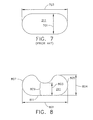
- FIG. 7 Another view of a prior art arrangement is shown in FIG. 7 , which illustrates a cross-section of a trailing edge opening 211, wherein the cross-sectional geometry has a substantially oval geometry.
- the trailing edge opening 211 known in the art was previously required to have a width 701 that is substantially uniform across the length 703 to provide sufficient ceramic core 501 strength during casting.
- FIG. 9 shows a known turbine blade 100 arrangement having a root plate 901 disposed on inlet openings 205.
- the root plate undesirably increases manufacturing costs and provides additional maintenance costs by requiring the installation of an additional component adjacent the turbine component.
- a first aspect of the present invention includes an airfoil component according to claim 1.
- Another aspect of the present invention includes a method for casting a gas turbine engine airfoil component, according to claim 7.
- An advantage of an embodiment of the present invention is that the amount of bleed air from the compressor may be reduced and gas turbine engine operation may be more efficient.
- Another advantage of an embodiment of the present invention is that the reduced cooling flow of cooling fluid from the trailing edge reduces or eliminates the need for other fluid flow restrictions, such as root plates.
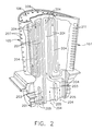
- FIG. 1 Illustrated in FIG. 1 is an exemplary turbine blade 100 for a gas turbine engine designed to be operated in a hot gas stream that flows in an axial flow downstream direction.
- combustion gases 101 are generated by a combustor (not shown) and flow downstream over the airfoil 103.
- the blade 100 includes a hollow airfoil 103 and a conventional root 104 used to secure the blade 100 to a rotor disk (not shown) of the gas turbine engine.
- the airfoil 103 includes an upstream leading edge 105, tip 106 and a downstream trailing edge 107 which is spaced chordally apart from the leading edge 105.
- the airfoil 103 extends longitudinally in a radial direction away from the root 104.
- the airfoil 101 includes an internal serpentine cooling circuit having cooling passages 201 traversing the hollow portions of airfoil 103.
- the configuration of cooling passageways 201 is not particularly limited and may include a plurality of circuits 203 that receives a cooling fluid 204, such as compressed air bled from the compressor of the gas turbine engine (not shown), through inlet openings 205.
- serpentine cooling circuit 203 are constructed so as to cause a serpentine cooling fluid 204 within the cooling circuit 203 to flow through the passages 201 and exit through leading edge openings 207, tip openings 209, trailing edge openings 211.
- airfoil 103 may include openings along the outer walls, the leading edge and/or the tip surfaces, as desired, to provide film cooling to various surfaces of the airfoil 103. As shown in FIG. 2 , these film cooling openings 207 and 209 may be disposed through the outer wall along leading edge 105 and tip 106, respectively.
- the present invention is not limited to the arrangement of passages 201 or openings 207 and 209 shown and may include any suitable arrangement of passages 201 that provides cooling to the airfoil 103.
- the trailing edge openings 211 receive a flow of cooling fluid 204 wherein the cooling fluid 204 flows through the trailing edge openings 211 and is discharged from the airfoil 103.
- Cooling air discharge apertures or trailing edge openings 211 are preferably designed to provide impingement cooling of the trailing edge 107.
- the present invention utilizes a configuration of trailing edge openings 211 that provides efficient cooling, without the need for a root plate or other cooling fluid 204 restriction, allowing for efficient gas turbine engine operation.
- FIGs. 1 and 2 Although an exemplary gas turbine blade 100 is illustrated in FIGs. 1 and 2 , the invention applies equally as well to substantially fixed turbine stator vanes having similar airfoils and turbine shrouds, which may be similarly cooled in accordance with the present invention.
- the airfoil 103 may have any other conventional features for enhancing the cooling thereof, such as turbulators or pins (not shown), which are well known in the art.
- thermal barrier coatings TBCs
- TBCs thermal barrier coatings
- FIG. 4 shows an airfoil 103 having trailing edge openings 211 having an arrangement of trailing edge openings 211 along trailing edge 107 according to an embodiment of the present invention.
- the trailing edge openings 211 having a pinched geometry that allow a flow rate of cooling fluid 204 that is less than the flow of cooling fluid 204 through the trailing edge openings 211 of FIG. 3 .
- the reduced cooling fluid 204 flow provides efficient cooling, without the need for a root plate or other cooling fluid 204 restriction, allowing for efficient gas turbine engine operation.
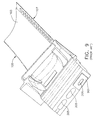
- FIG. 5 shows a core assembly for casting turbine blades with serpentine cooling circuits
- the internal ceramic core 501 is formed as a serpentine element having a number of long, thin branches.
- the internal ceramic core 501 is formed as a serpentine element having a number of long, thin branches.
- the ceramic core 501 has mechnical properties, such as strength, sufficient to withstand the pouring of casting material (e.g., superalloy metal) while maintaining the tight positioning requirement for the ceramic core 501 during casting.
- the casting of the turbine blade 100 may be performed using conventional turbine blade 100 casting methods.
- the turbine blade 100 may be investment cast from a directionally solidified or single crystal superalloy around ceramic core 501.
- the ceramic core 501 may be chemically removed to provide the hollow turbine blade 100.
- An embodiment of the present invention utilizes a ceramic core 501 that is formed utilizing cores insert projections 503 having a geometry corresponding to the pinched geometry trailing edge openings 211.
- the pinched trail edge openings 211 are cast utilizing ceramic core 501 insert projections 503 that provide a slot geometry having a pinched geometry to provide strength to the ceramic core 501 and provide sufficient cooling along the trailing edge opening 211 of the turbine component.
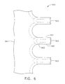
- FIG. 6 shows an enlarged view of portion 505 of FIG. 5 illustrating ceramic core 501 insert projections 503.
- the ceramic core 501 insert projection 503 geometry includes outer edge projections 601 providing one or more ribs or splines connected by a web portion 603, which extends between outer edge projections 601.
- the insert projections 503 preferably include a minimum and a maximum thickness across the length of the web portion 603.
- the web portion 603 may have a thickness (i.e., a thickness measured along an axis into the paper, as shown in FIGs 5 and 6 ) along the web portion 603 that is less than about 90% of the thickness of the outer edge projections 601, preferably the thickness of the web portion 603 is less than about 85% of the thickness of the outer edge projections 601 and more preferably the thickness web portion 603 is less than about 80% of the thickness of the outer edge projections 601.
- the combination of the outer edge projections 601 and the web portion 603 provides sufficient mechanical properties to permit casting of the turbine blade 100 and to maintain positioning during casting.
- the ceramic core 501 insert corresponds to geometry in the finished turbine blade 100 having trailing edge openings 211, when the ceramic core 501 insert is removed, that reduces or eliminates excessive flow of cooling fluid 204 at reduced cavity pressure during operation.
- the flow of cooling fluid 204 is sufficiently limited by the trailing edge openings 211 to reduce or eliminate the need for a root plate on the blade feed to limit the flow of cooling fluid 204.
- FIG. 8 illustrates an embodiment of the invention having a pinched geometry.
- pinched geometry it is meant that the cross-sectional geometry of the trailing edge opening 211 includes an elongated opening having a first dimension 801 arranged in the elongated direction and a second minimum dimension 803 and second maximum dimension 804 that are substantially perpendicular to the first dimension.
- the first dimension 801 includes a first end 805 and a second end 807 wherein the second minimum dimension 803 includes a minimum value at a location between the first end 805 and the second end 807.
- the trailing edge opening 211 has a pinched geometry wherein the first end 805 and second end 807 each include substantially circular cross-sectional geometries extending for a second maximum dimension 804 connected by a reduced thickness chord 809 extending along a side edge 811 of trailing edge opening 211.
- the second maximum dimension 804 may have a maximum near the first end 805 and second end 807 of about 0.013 inches and the second minimum dimension 803 may be 0.010 inches along chord 809.
- the second minimum dimension 803 may be less than or equal to about 90% of the second maximum dimension 804, preferably less than or equal to about 85% of the second maximum dimension 804 and still more preferably 80% of the second maximum dimension 804.
- the trailing edge opening 211 may include a plurality of second minimum dimensions 803 between first end 805 and second end 807, for example, wherein the second maximum dimension 804 is located at a location near the center of first dimension 801 a substantially T-shaped opening 211.
- the second maximum dimension 804 may extend in two directions past second minimum dimension 803.
- the present invention is not limited to the above configurations of the first dimension 801, the second minimum dimension 803 and second maximum dimension 804 and may include a plurality of each or both of the second minimum dimension 803 and second maximum dimension 804.
- the present invention utilizes the cross-sectional geometry formed to provide a reduced amount of cooling fluid 204 flow, while providing a sufficiently strong ceramic core 501 insert that allows casting of the blade 100. The cooling fluid 204 is therefore used more efficiently and less cooling fluid 204 is bled from the compressor for increasing the overall efficiency of operation of the gas turbine engine.
Claims (9)
- Composant de pale profilée (100) comprenant :un corps comportant un bord d'attaque (105) et un bord de fuite (107) ;un passage de refroidissement interne (201) à travers lequel s'écoule un fluide de refroidissement pendant l'utilisation et une pluralité d'ouvertures allongées (211) disposées le long du bord de fuite (107) et de manière adjacente à celui-ci et en communication avec le passage de refroidissement interne (201) ;caractérisé en ce que chaque ouverture (211) possède une géométrie pincée pour limiter l'écoulement du fluide de refroidissement.
- Composant (100) selon la revendication 1, dans lequel l'ouverture (211) possède une géométrie allongée ayant une première dimension (801) et une deuxième dimension (803, 804), la première dimension (801) ayant une première extrémité (805) et une deuxième extrémité (807) disposées aux extrémités opposées de l'ouverture (211) ; et
la deuxième dimension (803, 804) étant agencée perpendiculairement à la première dimension (801) et comportant en outre au moins une valeur minimale (803) et au moins une valeur maximale (804) disposées entre la première (805) et la deuxième extrémité (807). - Composant (100) selon la revendication 2, dans lequel l'au moins une valeur minimale (803) est inférieure à environ 90 % de la valeur maximale (804).
- Composant (100) selon la revendication 3, dans lequel l'au moins une valeur minimale (803) est inférieure à environ 80 % de la valeur maximale (804).
- Composant (100) selon l'une quelconque des revendications précédentes, dans lequel le composant (100) est une pale ou une aube de turbine.
- Composant (100) selon l'une quelconque des revendications précédentes, dans lequel le composant (100) est un carénage de turbine.
- Procédé de coulage d'un composant de pale profilée de moteur à turbine à gaz incluant la fourniture d'un insert de noyau comportant des projections d'insert de noyau avec des projections de bord externe (503) reliées par une partie de toile (603), les projections de bord externe (500) ayant une épaisseur le long de la partie de toile (603) supérieure à l'épaisseur de la partie de toile,
le coulage du composant de pale profilée sur l'insert de noyau,
le retrait de l'insert de noyau pour fournir un composant de pale profilée de moteur à turbine à gaz comportant des passages de refroidissement (201) et des ouvertures allongées (211) disposés le long du bord de fuite du composant de pale profilée et de manière adjacente à celui-ci et en communication avec les passages de refroidissement (210), caractérisé en ce que les ouvertures allongées (210) ont une géométrie pincée. - Procédé selon la revendication 7, dans lequel la partie de toile (603) possède une épaisseur le long de la partie de toile (103) inférieure à environ 90 % de l'épaisseur des projections de bord externe (601).
- Procédé selon la revendication 8, dans lequel la partie de toile (603) possède une épaisseur le long de la partie de toile (603) inférieure à environ 80 % de l'épaisseur des projections de bord externe (601).
Applications Claiming Priority (1)
| Application Number | Priority Date | Filing Date | Title |
|---|---|---|---|
| US11/616,176 US20100034662A1 (en) | 2006-12-26 | 2006-12-26 | Cooled airfoil and method for making an airfoil having reduced trail edge slot flow |
Publications (3)
| Publication Number | Publication Date |
|---|---|
| EP1942251A2 EP1942251A2 (fr) | 2008-07-09 |
| EP1942251A3 EP1942251A3 (fr) | 2010-09-08 |
| EP1942251B1 true EP1942251B1 (fr) | 2012-04-11 |
Family
ID=38984139
Family Applications (1)
| Application Number | Title | Priority Date | Filing Date |
|---|---|---|---|
| EP07123432A Expired - Fee Related EP1942251B1 (fr) | 2006-12-26 | 2007-12-18 | Aube refroidie ayant un flux réduit dans les fentes de bord de fuite et procédé de moulage associé |
Country Status (5)
| Country | Link |
|---|---|
| US (1) | US20100034662A1 (fr) |
| EP (1) | EP1942251B1 (fr) |
| JP (1) | JP2008163942A (fr) |
| CA (1) | CA2614031A1 (fr) |
| RU (1) | RU2007148893A (fr) |
Families Citing this family (16)
| Publication number | Priority date | Publication date | Assignee | Title |
|---|---|---|---|---|
| IT1394713B1 (it) * | 2009-06-04 | 2012-07-13 | Ansaldo Energia Spa | Pala di turbina |
| US8371814B2 (en) | 2009-06-24 | 2013-02-12 | Honeywell International Inc. | Turbine engine components |
| US8529193B2 (en) | 2009-11-25 | 2013-09-10 | Honeywell International Inc. | Gas turbine engine components with improved film cooling |
| US8628293B2 (en) | 2010-06-17 | 2014-01-14 | Honeywell International Inc. | Gas turbine engine components with cooling hole trenches |
| US8974182B2 (en) * | 2012-03-01 | 2015-03-10 | General Electric Company | Turbine bucket with a core cavity having a contoured turn |
| US9650900B2 (en) | 2012-05-07 | 2017-05-16 | Honeywell International Inc. | Gas turbine engine components with film cooling holes having cylindrical to multi-lobe configurations |
| US10107107B2 (en) * | 2012-06-28 | 2018-10-23 | United Technologies Corporation | Gas turbine engine component with discharge slot having oval geometry |
| US10113433B2 (en) | 2012-10-04 | 2018-10-30 | Honeywell International Inc. | Gas turbine engine components with lateral and forward sweep film cooling holes |
| US9957813B2 (en) | 2013-02-19 | 2018-05-01 | United Technologies Corporation | Gas turbine engine airfoil platform cooling passage and core |
| FR3025444B1 (fr) * | 2014-09-04 | 2016-09-23 | Snecma | Procede de production d'un noyau ceramique |
| FR3034128B1 (fr) * | 2015-03-23 | 2017-04-14 | Snecma | Noyau ceramique pour aube de turbine multi-cavites |
| US11021965B2 (en) | 2016-05-19 | 2021-06-01 | Honeywell International Inc. | Engine components with cooling holes having tailored metering and diffuser portions |
| EP3415250A1 (fr) * | 2017-06-15 | 2018-12-19 | Siemens Aktiengesellschaft | Noyau de coulage avec pont de croisement |
| DE102019125779B4 (de) * | 2019-09-25 | 2024-03-21 | Man Energy Solutions Se | Schaufel einer Strömungsmaschine |
| DE102020207646A1 (de) * | 2020-06-22 | 2021-12-23 | Siemens Aktiengesellschaft | Turbinenschaufel und Verfahren zum Bearbeiten einer solchen |
| CN113623014B (zh) * | 2021-07-22 | 2023-04-14 | 西安交通大学 | 一种燃气轮机透平叶片-轮盘联合冷却结构 |
Family Cites Families (31)
| Publication number | Priority date | Publication date | Assignee | Title |
|---|---|---|---|---|
| US3706508A (en) * | 1971-04-16 | 1972-12-19 | Sean Lingwood | Transpiration cooled turbine blade with metered coolant flow |
| US4236870A (en) * | 1977-12-27 | 1980-12-02 | United Technologies Corporation | Turbine blade |
| US4626169A (en) * | 1983-12-13 | 1986-12-02 | United Technologies Corporation | Seal means for a blade attachment slot of a rotor assembly |
| US4582467A (en) * | 1983-12-22 | 1986-04-15 | United Technologies Corporation | Two stage rotor assembly with improved coolant flow |
| US4529358A (en) * | 1984-02-15 | 1985-07-16 | The United States Of America As Represented By The Administrator Of The National Aeronautics And Space Administration | Vortex generating flow passage design for increased film cooling effectiveness |
| US4601638A (en) * | 1984-12-21 | 1986-07-22 | United Technologies Corporation | Airfoil trailing edge cooling arrangement |
| US4820123A (en) * | 1988-04-25 | 1989-04-11 | United Technologies Corporation | Dirt removal means for air cooled blades |
| GB2227965B (en) * | 1988-10-12 | 1993-02-10 | Rolls Royce Plc | Apparatus for drilling a shaped hole in a workpiece |
| GB8830152D0 (en) * | 1988-12-23 | 1989-09-20 | Rolls Royce Plc | Cooled turbomachinery components |
| US5651662A (en) * | 1992-10-29 | 1997-07-29 | General Electric Company | Film cooled wall |
| US6092982A (en) * | 1996-05-28 | 2000-07-25 | Kabushiki Kaisha Toshiba | Cooling system for a main body used in a gas stream |
| JP2810023B2 (ja) * | 1996-09-18 | 1998-10-15 | 株式会社東芝 | 高温部材冷却装置 |
| US5820774A (en) * | 1996-10-28 | 1998-10-13 | United Technologies Corporation | Ceramic core for casting a turbine blade |
| JPH1162507A (ja) * | 1997-08-11 | 1999-03-05 | Ishikawajima Harima Heavy Ind Co Ltd | フィルム冷却孔 |
| US6059529A (en) * | 1998-03-16 | 2000-05-09 | Siemens Westinghouse Power Corporation | Turbine blade assembly with cooling air handling device |
| DE19821770C1 (de) * | 1998-05-14 | 1999-04-15 | Siemens Ag | Verfahren und Vorrichtung zur Herstellung eines metallischen Hohlkörpers |
| US6126396A (en) * | 1998-12-09 | 2000-10-03 | General Electric Company | AFT flowing serpentine airfoil cooling circuit with side wall impingement cooling chambers |
| JP4092674B2 (ja) * | 1999-03-02 | 2008-05-28 | 日立金属株式会社 | セラミック中子を有するワックス模型の成型方法 |
| US6176677B1 (en) * | 1999-05-19 | 2001-01-23 | Pratt & Whitney Canada Corp. | Device for controlling air flow in a turbine blade |
| JP2001012204A (ja) * | 1999-06-30 | 2001-01-16 | Toshiba Corp | ガスタービン翼 |
| US6186741B1 (en) * | 1999-07-22 | 2001-02-13 | General Electric Company | Airfoil component having internal cooling and method of cooling |
| US6390774B1 (en) * | 2000-02-02 | 2002-05-21 | General Electric Company | Gas turbine bucket cooling circuit and related process |
| US6325593B1 (en) * | 2000-02-18 | 2001-12-04 | General Electric Company | Ceramic turbine airfoils with cooled trailing edge blocks |
| US6491496B2 (en) * | 2001-02-23 | 2002-12-10 | General Electric Company | Turbine airfoil with metering plates for refresher holes |
| US6416275B1 (en) * | 2001-05-30 | 2002-07-09 | Gary Michael Itzel | Recessed impingement insert metering plate for gas turbine nozzles |
| US6551062B2 (en) * | 2001-08-30 | 2003-04-22 | General Electric Company | Turbine airfoil for gas turbine engine |
| US6612811B2 (en) * | 2001-12-12 | 2003-09-02 | General Electric Company | Airfoil for a turbine nozzle of a gas turbine engine and method of making same |
| US6933459B2 (en) * | 2003-02-03 | 2005-08-23 | General Electric Company | Methods and apparatus for fabricating a turbine engine blade |
| US6974306B2 (en) * | 2003-07-28 | 2005-12-13 | Pratt & Whitney Canada Corp. | Blade inlet cooling flow deflector apparatus and method |
| US7328580B2 (en) * | 2004-06-23 | 2008-02-12 | General Electric Company | Chevron film cooled wall |
| US7510376B2 (en) * | 2005-08-25 | 2009-03-31 | General Electric Company | Skewed tip hole turbine blade |
-
2006
- 2006-12-26 US US11/616,176 patent/US20100034662A1/en not_active Abandoned
-
2007
- 2007-12-13 CA CA002614031A patent/CA2614031A1/fr not_active Abandoned
- 2007-12-18 EP EP07123432A patent/EP1942251B1/fr not_active Expired - Fee Related
- 2007-12-25 RU RU2007148893/06A patent/RU2007148893A/ru unknown
- 2007-12-26 JP JP2007333394A patent/JP2008163942A/ja active Pending
Also Published As
| Publication number | Publication date |
|---|---|
| CA2614031A1 (fr) | 2008-06-26 |
| EP1942251A2 (fr) | 2008-07-09 |
| JP2008163942A (ja) | 2008-07-17 |
| EP1942251A3 (fr) | 2010-09-08 |
| RU2007148893A (ru) | 2009-06-27 |
| US20100034662A1 (en) | 2010-02-11 |
Similar Documents
| Publication | Publication Date | Title |
|---|---|---|
| EP1942251B1 (fr) | Aube refroidie ayant un flux réduit dans les fentes de bord de fuite et procédé de moulage associé | |
| EP1070829B1 (fr) | Aube de turbomachine refroidie intérieurement | |
| US7377746B2 (en) | Airfoil cooling circuits and method | |
| EP1010859B1 (fr) | Système de refroidissement pour une aube de turbine ayant un circuit de refroidissement à trois passages | |
| EP2855857B1 (fr) | Joint d'étanchéité vis-à-vis de l'air externe de pale avec passages évidés | |
| EP2071126B1 (fr) | Aubes de turbine et procédé pour fabrication | |
| JP4453826B2 (ja) | 3回路タービンブレード | |
| EP1895098B1 (fr) | Pale de turbine refroidie améliorée à haute effectivité | |
| US8734108B1 (en) | Turbine blade with impingement cooling cavities and platform cooling channels connected in series | |
| US6955522B2 (en) | Method and apparatus for cooling an airfoil | |
| EP1055800B1 (fr) | Aube de turbine avec refroidissement interne | |
| US8348614B2 (en) | Coolable airfoil trailing edge passage | |
| JP4311919B2 (ja) | ガスタービンエンジン用のタービン翼形部 | |
| JP4256704B2 (ja) | ガスタービンエンジンのノズル組立体を冷却する方法及び装置 | |
| EP2614902B1 (fr) | Noyau pour processus de coulée | |
| EP2141326A2 (fr) | Profil d'aube doté d'un passage de refroidissement radial conique | |
| KR20060057508A (ko) | 선단부에 인접한 보조 냉각 채널을 갖는 에어포일 | |
| WO2001031171A1 (fr) | Structure de profil coule avec ouvertures ne necessitant pas de colmatage | |
| JP2001073705A (ja) | 優先的に冷却される後縁圧力壁を備えるタービン動翼 | |
| US7387492B2 (en) | Methods and apparatus for cooling turbine blade trailing edges | |
| US11230929B2 (en) | Turbine component with dust tolerant cooling system | |
| EP3594449B1 (fr) | Aube de turbine avec système de refroidissement à tolérance à la poussière | |
| US11333042B2 (en) | Turbine blade with dust tolerant cooling system | |
| EP3645838B1 (fr) | Aube de turbine avec caracteristiques de bord de fuite et noyau de coulée | |
| CN113677872B (zh) | 用于制造涡轮发动机扇叶的金属铸造组件和失蜡方法 |
Legal Events
| Date | Code | Title | Description |
|---|---|---|---|
| PUAI | Public reference made under article 153(3) epc to a published international application that has entered the european phase |
Free format text: ORIGINAL CODE: 0009012 |
|
| AK | Designated contracting states |
Kind code of ref document: A2 Designated state(s): AT BE BG CH CY CZ DE DK EE ES FI FR GB GR HU IE IS IT LI LT LU LV MC MT NL PL PT RO SE SI SK TR |
|
| AX | Request for extension of the european patent |
Extension state: AL BA HR MK RS |
|
| PUAL | Search report despatched |
Free format text: ORIGINAL CODE: 0009013 |
|
| AK | Designated contracting states |
Kind code of ref document: A3 Designated state(s): AT BE BG CH CY CZ DE DK EE ES FI FR GB GR HU IE IS IT LI LT LU LV MC MT NL PL PT RO SE SI SK TR |
|
| AX | Request for extension of the european patent |
Extension state: AL BA HR MK RS |
|
| RIC1 | Information provided on ipc code assigned before grant |
Ipc: B22C 9/24 20060101ALI20100730BHEP Ipc: B22C 9/04 20060101ALI20100730BHEP Ipc: F01D 5/08 20060101ALI20100730BHEP Ipc: F01D 5/18 20060101AFI20080207BHEP |
|
| 17P | Request for examination filed |
Effective date: 20110308 |
|
| AKX | Designation fees paid |
Designated state(s): DE FR GB |
|
| RTI1 | Title (correction) |
Free format text: COOLED AIRFOIL HAVING REDUCED TRAILING EDGE SLOT FLOW AND CORRESPONDING CASTING METHOD |
|
| GRAP | Despatch of communication of intention to grant a patent |
Free format text: ORIGINAL CODE: EPIDOSNIGR1 |
|
| GRAS | Grant fee paid |
Free format text: ORIGINAL CODE: EPIDOSNIGR3 |
|
| GRAA | (expected) grant |
Free format text: ORIGINAL CODE: 0009210 |
|
| AK | Designated contracting states |
Kind code of ref document: B1 Designated state(s): DE FR GB |
|
| REG | Reference to a national code |
Ref country code: GB Ref legal event code: FG4D |
|
| REG | Reference to a national code |
Ref country code: DE Ref legal event code: R096 Ref document number: 602007021855 Country of ref document: DE Effective date: 20120606 |
|
| PLBE | No opposition filed within time limit |
Free format text: ORIGINAL CODE: 0009261 |
|
| STAA | Information on the status of an ep patent application or granted ep patent |
Free format text: STATUS: NO OPPOSITION FILED WITHIN TIME LIMIT |
|
| PGFP | Annual fee paid to national office [announced via postgrant information from national office to epo] |
Ref country code: GB Payment date: 20121227 Year of fee payment: 6 |
|
| 26N | No opposition filed |
Effective date: 20130114 |
|
| PGFP | Annual fee paid to national office [announced via postgrant information from national office to epo] |
Ref country code: FR Payment date: 20130110 Year of fee payment: 6 |
|
| PGFP | Annual fee paid to national office [announced via postgrant information from national office to epo] |
Ref country code: DE Payment date: 20121231 Year of fee payment: 6 |
|
| REG | Reference to a national code |
Ref country code: DE Ref legal event code: R097 Ref document number: 602007021855 Country of ref document: DE Effective date: 20130114 |
|
| REG | Reference to a national code |
Ref country code: DE Ref legal event code: R119 Ref document number: 602007021855 Country of ref document: DE |
|
| GBPC | Gb: european patent ceased through non-payment of renewal fee |
Effective date: 20131218 |
|
| REG | Reference to a national code |
Ref country code: DE Ref legal event code: R119 Ref document number: 602007021855 Country of ref document: DE Effective date: 20140701 |
|
| REG | Reference to a national code |
Ref country code: FR Ref legal event code: ST Effective date: 20140829 |
|
| PG25 | Lapsed in a contracting state [announced via postgrant information from national office to epo] |
Ref country code: DE Free format text: LAPSE BECAUSE OF NON-PAYMENT OF DUE FEES Effective date: 20140701 |
|
| PG25 | Lapsed in a contracting state [announced via postgrant information from national office to epo] |
Ref country code: GB Free format text: LAPSE BECAUSE OF NON-PAYMENT OF DUE FEES Effective date: 20131218 Ref country code: FR Free format text: LAPSE BECAUSE OF NON-PAYMENT OF DUE FEES Effective date: 20131231 |