EP1942008B1 - Casing-in machine with book transfer device - Google Patents
Casing-in machine with book transfer device Download PDFInfo
- Publication number
- EP1942008B1 EP1942008B1 EP07022809A EP07022809A EP1942008B1 EP 1942008 B1 EP1942008 B1 EP 1942008B1 EP 07022809 A EP07022809 A EP 07022809A EP 07022809 A EP07022809 A EP 07022809A EP 1942008 B1 EP1942008 B1 EP 1942008B1
- Authority
- EP
- European Patent Office
- Prior art keywords
- book
- books
- casing
- machine according
- delivery
- Prior art date
- Legal status (The legal status is an assumption and is not a legal conclusion. Google has not performed a legal analysis and makes no representation as to the accuracy of the status listed.)
- Not-in-force
Links
Images

Classifications
-
- B—PERFORMING OPERATIONS; TRANSPORTING
- B42—BOOKBINDING; ALBUMS; FILES; SPECIAL PRINTED MATTER
- B42C—BOOKBINDING
- B42C11/00—Casing-in
- B42C11/04—Machines or equipment for casing-in or applying covers to books
-
- B—PERFORMING OPERATIONS; TRANSPORTING
- B42—BOOKBINDING; ALBUMS; FILES; SPECIAL PRINTED MATTER
- B42C—BOOKBINDING
- B42C9/00—Applying glue or adhesive peculiar to bookbinding
- B42C9/0006—Applying glue or adhesive peculiar to bookbinding by applying adhesive to a stack of sheets
- B42C9/0012—Applying glue or adhesive peculiar to bookbinding by applying adhesive to a stack of sheets with a roller
- B42C9/0031—Applying glue or adhesive peculiar to bookbinding by applying adhesive to a stack of sheets with a roller with continuous flow of stacks of sheets
- B42C9/0037—Applying glue or adhesive peculiar to bookbinding by applying adhesive to a stack of sheets with a roller with continuous flow of stacks of sheets and subsequently applying a cover
Definitions
- the invention relates to a Buchein mentalmaschine with the books astride transporting support plates of a circulating conveyor and with a book display, consisting of a arranged in the plane of movement of the support plates, a through hole for the support plates having Abstreiforgan on which the downwardly migrating books to release from the Supporting support plates, with a Auslege coupled for subsequent lateral interpretation of the books with respect to the plane of movement of the support plates.
- a book-hanger of the type described is known, with a book display shown in simplified form.
- the book blocks are transported astride means of support plates of a circulation conveyor from bottom to top, glued and provided with a book cover.
- the books get during their downward movement in a laying plane lying in the plane of movement with a drum-shaped, about its longitudinal axis back and forth rotatable scraper and attached to this Auslegerechen.
- the wiper member has a passageway for passing the support plates as the book is being stripped from the saddle plate.
- the books are taken over by the rotational movement of the wiper from the Auslegerechen and stored on an export belt.
- the invention has for its object to provide a Buchein vonmaschine with a book display of the generic type, which allows for high clock performance reliable and proper interpretation of the books from the circulation conveyor.
- the delivery device comprises support means with at least the books laterally supporting support rails, wherein the support means from the stripping position in a plane parallel to the movement plane delivery position for the books are movable back and forth.
- the books are transferred under constant support from the stripping position in the delivery position.
- the books are no longer dumped or overturned.
- the books are permanently supported, without the books are released in the meantime.
- the book form is preserved. Due to the gentle treatment, the adhesive bond between book block and book cover is not endangered.
- the support means are movable substantially perpendicular to the plane of movement of the support plates, so that the books are designed while maintaining their vertical position in the plane of movement of the support plates parallel delivery position.
- two units of support means can take over the books from the stripping position and transfer in each case in display positions on opposite sides of the plane of movement of the support plates.
- the two units of support means are arranged at a defined distance from each other on a reciprocable carriage.
- the wiper member is provided as said support means. It is moved laterally out of the plane of movement of the support plates, carrying thereby the book deposited on it.
- the books may be laterally supported by support rails.
- the books can be transferred laterally clamped in an alternative to the movable wiper alone of the support rails or they are carried by the wiper, under lateral support transferred from the support rails.
- the support rails are formate adjustable with respect to a guide width to book thickness. They may be L-shaped, each with a leg oriented in the direction of the book height and a leg oriented in the direction of the book width, so that the pages of the book are partially released for subsequent transport.
- the support rails can be closed and openable.
- the wiper member In order to reduce the Aufsetzilia of remote from the support plates on the wiper member book, the wiper member can be moved downwards at the moment of placement.
- the pivot axis of the book pliers can be adjusted in size horizontally parallel to him, so that the position of the books in the horizontal direction, in which the book height extends, can be fixed, for example.
- the reference edge when turning the books from head or foot to book center or vice versa.
- the pivot axis of the book pliers in the vertical direction can be adjusted in size parallel to him, so that the position of the books in the vertical direction in which the book width extends, can be fixed, for example.
- the reference edge Turn the Books from frontal to spine or vice versa, where the back shape, whether straight or round, and the roundness can be taken into account.
- book blocks 2 are connected with book covers 3 to books 1.
- the book blocks 2 are fed by a book block transport chain 10.1 a circulating conveyor 10.3, with which the book blocks 2 are transported in an always vertical position astride support plates 10.4. They are thereby provided in the vertical conveying movement by glue rollers 10.6 on the attachments over the entire surface with adhesive and connected to a book cover 3 supplied via a book cover transport 10.2.
- the books 1 created thereby can subsequently be guided through pressure rollers 10.7.
- the books 1 move during their downward movement into a lying in the plane of movement 10.5 of the support plates 10.4 book display 20, the books 1 with their front section 1 b on a wiper 20.5 put on, which has a passage slot 20.5a for passing the support plates 10.4 ( please refer Fig. 4 ).
- the stripped from the support plate 10.4 book 1 is now according to the invention of supporting means of a book 20.1 and 20.2 constantly supported from this Abstreifposition 20.10 in a movement plane 10.5 laterally offset delivery position 20.11 and 20.12 transferred.
- the wiper 20.5 itself is provided, on which the book 1 is supported with its front section 1 b.
- the book 1 is therefore no longer pushed down as in the prior art by wiper 20.5, but supported by this or moved out of the plane of movement 10.5 of the support plates 10.4 moved out.
- the wiper 20.5 is for this purpose on a in a guide rail 20.4 perpendicular to the movement plane 10.5 reciprocable carriage 20.3, so that the books 1 are designed while maintaining their vertical position in a plane parallel to the plane of movement 10.5.
- left and right support rails 20.6 and 20.7 are provided as the second support means, which are open when stripping the respective book 1 of the support plate 10.4 in format-adjustable guide width and immediately before the sideways movement of the carriage 20.3 to a narrow politicianssutz or with less Clamping force are closed, for lateral support of the book 1.
- the necessary control means are not explicitly shown in the figures, but symbolized by movement arrows.
- a first and a second book receivers 20.1 and 20.2 can take over the books 1 from the stripping position 20.10 and transfer them to a movement plane 10.5 left and right display position 20.11 and 20.12.
- the two book receptacles 20.1 and 20.2 are arranged at a defined distance from each other on the reciprocating carriage 20.3, so that simultaneously with the Ausfuelhub the first book 20.1 recording the second book 20.2 is moved from its right delivery position 20.12 in the stripping 20.10 and vice versa.
- the wiper 20.5 can be moved downwards at the moment of placement.
- the book to be executed 1 can be kept clamped solely by the left and right support rails 20.6 and 20.7. It would be necessary to a single, remaining in the plane of movement 10.5 scraper 20.5, which is displaceable in the execution of the book 1 in a lowered position.
- the hanging of the book block 2 in the book cover 3 usually follows the pressing of the book 1, to achieve a wrinkle-free and permanent bonding of the attachments of the book block 2 with the inner sides of the book cover.
- This operation of the Ganzpressens takes place on so-called Buchform- and -pressmaschinen in combination with the Falzeinbute, in which the Buchorfalze 1 c are formed and glued.
- the books are the Buchform- and -pressmaschinen with downward spine 1a to feed, for alignment of the back 1a and the book 1 on an alignment table 43.1 formed from prism bars 43.2.
- the present book display 20 is extended with a double-book pliers 30, with the books 1 from the left and right display position 20.11 and 20.12 in a second left or right display position 30.11 and 30.12 can be converted, the books turned and 1 with their Back 1a are placed directly on said alignment table 43.1.
- the double-book pliers 30 has to take over the split book flow on a left and a right book pliers 30.1 and 30.2, which are about a pivot axis 30.3 gegentechnisch 180 ° back and forth pivotally, which is symbolized in the figures by corresponding movement arrows.
- the books 1 are laterally gripped with left and right jaws 30.4 and 30.5 in an area left free by the left and right support rails 20.6 and 20.7.
- the support rails 20.6, 20.7 are for this purpose L-shaped, each oriented in the direction of book height, horizontally extending legs 20.8 and oriented in the direction book width, vertically extending leg 20.9.
- the position of the books in the horizontal direction, in which the book height extends can be fixed.
- the books 1 are transported astride the support plates 10.4 with the solid-fixed foot edge 20.13.
- a format-firm book center 30.13 is desired so that the books 1 are centrally clamped in the pressing devices.
- This reference edge change can be automated in format changes by a corresponding horizontal pivot adjustment 30.6 depending on the respective book height change.
- the vertical pivot adjustment 30.7 With the vertical pivot adjustment 30.7, the position of the books in the vertical direction, in which the book width extends, can be fixed. After placing on the wiper 20.5 the books 1 are performed with the front section 1 b as a fixed reference edge 20.14 from the book-hanger 10. The Buchform- and -pressmaschine are meanwhile books 1 with the back 1a as a fixed reference edge 30.14 supply.
- This Reference edge change can be automated in format changes by a corresponding vertical pivot adjustment 30.7 depending on the respective book width change, the back shape, whether straight or round, and the Rundungshunt can be considered.
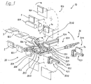
- Fig. 1 Initially, the situation is shown that a book 1 is worn by stripping of the support plate 10.4 of the Abstreiforgan 20.5 of the first book 20.1, while a run from the second book 20.2 to the right delivery position 20.12 Book 1 of the right book pliers 30.2 of the double-tong 30th gripped in the second right delivery position 30.12 is turned. At the same time, the left-hand pliers 30.1 move back to the first left-hand delivery position 20.11. She has just turned off a book 1 in the second left delivery position 30.11 on the alignment table 43.1. The carriage 20.3 with the two book receptacles 20.1 and 20.2 starts with a sideways movement to the left.
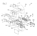
- the carriage 20.3 has reached its left end position, just in time before the left book tongs 30.1 with open jaws 30.4 and 30.5 moves over the book located in the left book holder 20.1, to seize this book, and just in time before the carrying plate 10.4 straddles it transported book 1 between the support rails 20.6 and 20.7 or through the passage opening 20.5a of the Abstreiforgans 20.5 of the right book 20.2 moves, for stripping the book 1 on the Abstreiforgans 20.5.
Description
Die Erfindung betrifft eine Bucheinhängemaschine mit die Bücher rittlings in senkrechter Lage transportierenden Tragplatten eines Umlaufförderers und mit einer Buchauslage, bestehend aus einem in der Bewegungsebene der Tragplatten angeordneten, eine Durchgangsöffnung für die Tragplatten aufweisenden Abstreiforgan, auf dem sich die abwärts wandernden Bücher zur Freigabe von den Tragplatten abstützen, mit einer Auslegeeinrichtung zum nachfolgend seitlichen Auslegen der Bücher in Bezug auf die Bewegungsebene der Tragplatten.The invention relates to a Bucheinhängemaschine with the books astride transporting support plates of a circulating conveyor and with a book display, consisting of a arranged in the plane of movement of the support plates, a through hole for the support plates having Abstreiforgan on which the downwardly migrating books to release from the Supporting support plates, with a Auslegeeinrichtung for subsequent lateral interpretation of the books with respect to the plane of movement of the support plates.
Aus der
In der
Aus der
Bei den bekannten Buchauslagesystemen werden die Bücher aus ihrer senkrechten Lage quasi umgestoßen. Der Ablegerechen fängt die Fallbewegung auf und legt die Bücher in einer um eine zum Abstreiforgan parallele Achse schwenkenden Niederlegebewegung auf ein kontinuierlich laufendes Ausfuhrband ab. Frisch eingehängte Bücher werden dabei erheblichen Belastungen ausgesetzt, was zur Deformation der Bücher führt und die geschaffene Verbindung zwischen Buchblock und Buchdecke gefährdet. Auftretende Relativbewegungen mit dem Abstreiforgan, dem Ablegerechen und/oder dem Ausfuhrband können bei Büchern mit empfindlichen Buchdeckenbezügen zu Markierungen führen.In the known book display systems, the books are virtually knocked over from their vertical position. The Ablegerechen catches the falling motion and places the books in a down to a Abstreiforgan parallel axis pivoting depositing movement on a continuously running export belt. Freshly hung books are subjected to considerable stress, which leads to the deformation of the books and jeopardizes the connection created between book block and book cover. Occurring relative movements with the wiper, the Ablegerechen and / or the export belt can lead to bookmarks with sensitive book covers to markings.
Der Erfindung liegt die Aufgabe zugrunde, eine Bucheinhängemaschine mit einer Buchauslage der gattungsgemäßen Art zu schaffen, die bei hoher Taktleistung ein zuverlässiges und einwandfreies Auslegen der Bücher aus dem Umlaufförderer ermöglicht.The invention has for its object to provide a Bucheinhängemaschine with a book display of the generic type, which allows for high clock performance reliable and proper interpretation of the books from the circulation conveyor.
Diese Aufgabe wird erfindungsgemäß dadurch gelöst, dass die Auslegeeinrichtung Stützmittel mit zumindest die Bücher seitlich abstützenden Stützschienen umfasst, wobei die Stützmittel von der Abstreifposition in eine zur Bewegungsebene parallele Auslageposition für die Bücher hin und her bewegbar sind. Die Bücher werden unter ständiger Abstützung aus der Abstreifposition in die Auslageposition überführt.This object is achieved in that the delivery device comprises support means with at least the books laterally supporting support rails, wherein the support means from the stripping position in a plane parallel to the movement plane delivery position for the books are movable back and forth. The books are transferred under constant support from the stripping position in the delivery position.
Die Bücher werden nicht mehr abgekippt oder umgeworfen. Beim Auslegen aus dem Umlaufförderer werden die Bücher permanent gestützt, ohne dass die Bücher zwischenzeitlich losgelassen werden. Die Buchform bleibt erhalten. Durch die schonende Behandlung ist die Klebeverbindung zwischen Buchblock und Buchdecke nicht gefährdet.The books are no longer dumped or overturned. When laying out of the circulation conveyor, the books are permanently supported, without the books are released in the meantime. The book form is preserved. Due to the gentle treatment, the adhesive bond between book block and book cover is not endangered.
Die abhängigen Ansprüche definieren bevorzugte Ausführungsformen der erfindungsgemäßen Buchauslage.The dependent claims define preferred embodiments of the book display according to the invention.
Vorzugsweise sind die Stützmittel im Wesentlichen senkrecht zur Bewegungsebene der Tragplatten bewegbar, sodass die Bücher unter Beibehaltung ihrer senkrechten Lage in die zur Bewegungsebene der Tragplatten parallele Auslageposition ausgelegt werden.Preferably, the support means are movable substantially perpendicular to the plane of movement of the support plates, so that the books are designed while maintaining their vertical position in the plane of movement of the support plates parallel delivery position.
Zur Aufteilung des Buchstroms können abwechselnd zwei Einheiten von Stützmitteln die Bücher aus der Abstreifposition übernehmen und jeweils in Auslagepositionen auf sich gegenüberliegenden Seiten der Bewegungsebene der Tragplatten überführen. Vorzugsweise sind dabei die beiden Einheiten von Stützmitteln in einem definierten Abstand zueinander auf einem hin und her bewegbaren Schlitten angeordnet.In order to divide the book flow alternately two units of support means can take over the books from the stripping position and transfer in each case in display positions on opposite sides of the plane of movement of the support plates. Preferably In this case, the two units of support means are arranged at a defined distance from each other on a reciprocable carriage.
Bei einer bevorzugten Ausführungsform gemäß Anspruch 5 ist das Abstreiforgan als besagtes Stützmittel vorgesehen. Es wird seitlich aus der Bewegungsebene der Tragplatten herausbewegt und trägt dabei das auf ihm abgesetzte Buch.In a preferred embodiment according to claim 5, the wiper member is provided as said support means. It is moved laterally out of the plane of movement of the support plates, carrying thereby the book deposited on it.
Bei der Überführung können die Bücher von Stützschienen seitlich abgestützt sein. Dabei können die Bücher in Alternative zum verfahrbaren Abstreiforgan allein von den Stützschienen seitlich eingeklemmt überführt werden oder sie werden, vom Abstreiforgan getragen, unter seitlicher Abstützung von den Stützschienen überführt. Vorzugsweise sind die Stützschienen hinsichtlich einer Führungsweite auf Buchdicke formateinstellbar. Sie können L-förmig ausgebildet sein, mit jeweils einem in Richtung Buchhöhe orientierten Schenkel und einem in Richtung Buchbreite orientierten Schenkel, sodass die Buchseiten teilweise für nachfolgende Transportmittel freigelassen sind. Zum seitlichen Einspannen der Bücher während der seitwärts gerichteten Auslegebewegung können die Stützschienen schließ- und öffnebar sein.During transfer, the books may be laterally supported by support rails. The books can be transferred laterally clamped in an alternative to the movable wiper alone of the support rails or they are carried by the wiper, under lateral support transferred from the support rails. Preferably, the support rails are formate adjustable with respect to a guide width to book thickness. They may be L-shaped, each with a leg oriented in the direction of the book height and a leg oriented in the direction of the book width, so that the pages of the book are partially released for subsequent transport. For lateral clamping of the books during the sideways orientation movement, the support rails can be closed and openable.
Zur Verringerung der Aufsetzgeschwindigkeit des von den Tragplatten auf das Abstreiforgan abgesetzten Buches kann das Abstreiforgan im Moment des Aufsetzens abwärts bewegt sein.In order to reduce the Aufsetzgeschwindigkeit of remote from the support plates on the wiper member book, the wiper member can be moved downwards at the moment of placement.
In bevorzugter Weiterausgestaltung ist eine der Buchauslage nachgeordnete, um eine Achse schwenkende und die Bücher aus der besagten, ersten Auslageposition seitlich einspannend übernehmende Buchzange vorgesehen, zum Wenden und Überführen der Bücher in eine zweite Auslageposition.In a preferred embodiment of the book display subordinate, pivoting about an axis and the books from the said first delivery position laterally chucking acquiring book tongs provided for turning and transferring the books in a second delivery position.
Zur definierten Auslage der Bücher in der zweiten Auslageposition kann die Schwenkachse der Buchzange in horizontaler Richtung parallel zu sich formatverstellbar werden, sodass die Position der Bücher in horizontaler Richtung, in welcher sich die Buchhöhe erstreckt, festlegbar ist, bspw. zum Wechseln der Bezugskante beim Wenden der Bücher von Kopf bzw. Fuß auf Buchmitte oder umgekehrt.For defined display of the books in the second delivery position, the pivot axis of the book pliers can be adjusted in size horizontally parallel to him, so that the position of the books in the horizontal direction, in which the book height extends, can be fixed, for example. For changing the reference edge when turning the books from head or foot to book center or vice versa.
Zur definierten Auslage der Bücher in der zweiten Auslageposition kann außerdem die Schwenkachse der Buchzange in vertikaler Richtung parallel zu sich formatverstellbar werden, sodass die Position der Bücher in vertikaler Richtung, in welcher sich die Buchbreite erstreckt, festlegbar ist, bspw. zum Wechseln der Bezugskante beim Wenden der Bücher von Vorderschnitt auf Buchrücken oder umgekehrt, wobei die Rückenform, ob gerade oder rund, und das Rundungsmaß Berücksichtigung finden kann.For defined display of books in the second delivery position also the pivot axis of the book pliers in the vertical direction can be adjusted in size parallel to him, so that the position of the books in the vertical direction in which the book width extends, can be fixed, for example. For changing the reference edge Turn the Books from frontal to spine or vice versa, where the back shape, whether straight or round, and the roundness can be taken into account.
Die Merkmale der vorliegenden Erfindung werden in der folgenden Beschreibung einer bevorzugten Ausführungsform anhand der beigefügten, nachstehend aufgeführten Zeichnungen näher erläutert. Es zeigen
- Fig. 1
- in schematisch vereinfachter Perspektivansicht eine Bucheinhängemaschine mit einer Buchauslage und nachgeordneter Buchzange im Moment des Abstrei- fens eines Buches von einer Tragplatte;
- Fig. 2
- in gleicher Ansicht die Bucheinhängemaschine mit einem in eine seitliche Aus- lageposition überführten Buch;
- Fig. 3
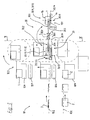
- die Bucheinhängemaschine, Buchauslage und die nachgeordnete Buchzange in einer schematischen Seitenansicht; und
- Fig. 4
- eine Schnittansicht von der Buchauslage gemäß Schnittverlauf IV in
Fig. 3 .
- Fig. 1
- in a schematically simplified perspective view of a book-hanger with a book display and subordinate book tongs at the moment of stripping a book from a support plate;
- Fig. 2
- in the same view, the book-hanger with a book transferred to a lateral position;
- Fig. 3
- the book-hanger, book display and the subordinate book tongs in a schematic side view; and
- Fig. 4
- a sectional view of the book display according to section line IV in
Fig. 3 ,
In der Bucheinhängemaschine 10 werden Buchblocks 2 mit Buchdecken 3 zu Büchern 1 verbunden. Die Buchblocks 2 werden von einer Buchblocktransportkette 10.1 einem Umlaufförderer 10.3 zugeführt, mit dem die Buchblocks 2 in stets senkrechter Lage rittlings auf Tragplatten 10.4 transportiert werden. Sie werden dabei in vertikaler Förderbewegung durch Leimwalzen 10.6 an den Vorsätzen vollflächig mit Klebstoff versehen und mit einer über einen Buchdeckentransport 10.2 zugeführten Buchdecke 3 verbunden. Die dadurch geschaffenen Bücher 1 können anschließend noch durch Andrückwalzen 10.7 hindurch geführt werden.In
Im weiteren Verlauf gelangen die Bücher 1 während ihrer Abwärtsbewegung in eine in der Bewegungsebene 10.5 der Tragplatten 10.4 liegende Buchauslage 20, wobei die Bücher 1 mit ihrem Vorderschnitt 1 b auf ein Abstreiforgan 20.5 aufsetzen, das einen Durchlassschlitz 20.5a zum Hindurchführen der Tragplatten 10.4 aufweist (siehe
Als erstes Stützmittel ist hierbei das Abstreiforgan 20.5 selbst vorgesehen, auf dem sich das Buch 1 mit seinem Vorderschnitt 1 b abstützt. Das Buch 1 wird also nicht mehr wie im Stand der Technik vom Abstreiforgan 20.5 herunter gestoßen, sondern von diesem gestützt bzw. getragen aus der Bewegungsebene 10.5 der Tragplatten 10.4 herausbewegt. Das Abstreiforgan 20.5 befindet sich hierzu an einem in einer Führungsschiene 20.4 senkrecht zur Bewegungsebene 10.5 hin und her bewegbaren Schlitten 20.3, sodass die Bücher 1 unter Beibehaltung ihrer senkrechten Lage in eine zur Bewegungsebene 10.5 parallelen Ebene ausgelegt werden.As the first support means in this case the wiper 20.5 itself is provided, on which the
Zusätzlich zum Abstreiforgan 20.5 sind als zweite Stützmittel linke und rechte Stützschienen 20.6 und 20.7 vorgesehen, die beim Abstreifen des jeweiligen Buches 1 von der Tragplatte 10.4 in auf Buchdicke formateinstellbare Führungsweite geöffnet sind und unmittelbar vor der Seitwärtsbewegung des Schlittens 20.3 auf ein enges Führungsmaß oder mit geringer Klemmkraft geschlossen werden, zur seitlichen Abstützung des Buches 1. Die dafür erforderlichen Steuermittel sind in den Figuren nicht explizit dargestellt, sondern durch Bewegungspfeile symbolisiert.In addition to the wiper 20.5 left and right support rails 20.6 and 20.7 are provided as the second support means, which are open when stripping the
Zur Aufteilung des im Umlaufförderer 10.3 befindlichen Buchstroms können abwechselnd eine erste und eine zweite Buchaufnahme 20.1 und 20.2 die Bücher 1 aus der Abstreifposition 20.10 übernehmen und in eine zur Bewegungsebene 10.5 linke und rechte Auslageposition 20.11 und 20.12 überführen. Die beiden Buchaufnahmen 20.1 und 20.2 sind in einem definierten Abstand zueinander auf dem hin und her bewegbaren Schlitten 20.3 angeordnet, sodass gleichzeitig mit dem Ausführhub der ersten Buchaufnahme 20.1 die zweite Buchaufnahme 20.2 aus ihrer rechten Auslageposition 20.12 in die Abstreifposition 20.10 bewegt wird und umgekehrt.To divide the book flow located in the circulating conveyor 10.3, alternately a first and a second book receivers 20.1 and 20.2 can take over the
Zur Verringerung der Aufsetzgeschwindigkeit des von den Tragplatten 10.4 auf das Abstreiforgan 20.5 abgesetzten Buches 1 kann das Abstreiforgan 20.5 im Moment des Aufsetzens abwärts bewegt sein. In alternativer Ausgestaltung ohne Bezug in den Figuren kann das auszuführende Buch 1 allein von den linken und rechten Stützschienen 20.6 und 20.7 eingeklemmt gehalten sein. Es würde dazu ein einziges, in der Bewegungsebene 10.5 verbleibendes Abstreiforgan 20.5 erforderlich sein, das beim Ausführen des Buches 1 in eine abgesenkte Position versetzbar ist.To reduce the Aufsetzgeschwindigkeit of the deposited from the support plates 10.4 on the wiper 20.5
Dem Einhängen des Buchblocks 2 in die Buchdecke 3 folgt meist noch das Einpressen des Buches 1, zur Erreichung einer faltenfreien und dauerhaften Verklebung der Vorsätze des Buchblocks 2 mit den inneren Seiten der Buchdeckel. Dieser Arbeitsgang des Ganzpressens erfolgt auf sogenannten Buchform- und -pressmaschinen in Kombination mit dem Falzeinbrennen, bei dem die Buchdeckenfalze 1 c geformt und verklebt werden. Die Bücher sind den Buchform- und -pressmaschinen mit nach unten gerichtetem Rücken 1a zuzuführen, zur Ausrichtung des Rücken 1a bzw. des Buches 1 auf einem aus Prismenleisten 43.2 gebildeten Ausrichttisch 43.1.The hanging of the
Die vorliegende Buchauslage 20 ist mit einer Doppelbuchzange 30 erweitert, mit der die Bücher 1 aus der jeweils linken und rechten Auslageposition 20.11 bzw. 20.12 in eine zweite linke bzw. rechte Auslageposition 30.11 bzw. 30.12 überführbar sind, wobei die Bücher 1 gewendet und mit ihrem Rücken 1a direkt auf besagtem Ausrichttisch 43.1 abgesetzt werden.The
Die Doppelbuchzange 30 weist zur Übernahme des aufgeteilten Buchstroms eine linke und eine rechte Buchzange 30.1 und 30.2 auf, die um eine Schwenkachse 30.3 gegengleich um 180° hin und her schwenkbar sind, was in den Figuren durch entsprechende Bewegungspfeile symbolisiert ist. Die Bücher 1 werden mit einer linken und rechten Klemmbacke 30.4 und 30.5 in einem von den linken und rechten Stützschienen 20.6 und 20.7 freigelassenen Bereich seitlich erfasst. Die Stützschienen 20.6, 20.7 sind hierzu L-förmig ausgebildet, mit jeweils einem in Richtung Buchhöhe orientierten, horizontal verlaufenden Schenkel 20.8 und einem in Richtung Buchbreite orientierten, vertikal verlaufenden Schenkel 20.9.The double-
Durch parallel zu sich in horizontaler und vertikaler Richtung erfolgende Drehpunktverstellungen 30.6, 30.7 der Schwenkachse 30.3 - in
Mit der horizontalen Drehpunktverstellung 30.6 ist die Position der Bücher in horizontaler Richtung, in welcher sich die Buchhöhe erstreckt, festlegbar. In der Bucheinhängemaschine 10 werden die Bücher 1 mit formatfester Fußkante 20.13 rittlings auf den Tragplatten 10.4 transportiert. In der Buchform- und -pressmaschine hingegen ist eine formatfeste Buchmitte 30.13 erwünscht, damit die Bücher 1 in den Pressvorrichtungen mittig eingespannt sind. Dieser Bezugskantenwechsel kann bei Formatänderungen durch eine entsprechende horizontale Drehpunktverstellung 30.6 in Abhängigkeit von der jeweiligen Buchhöhenänderung automatisiert werden.With the horizontal pivot adjustment 30.6, the position of the books in the horizontal direction, in which the book height extends, can be fixed. In the book-
Mit der vertikalen Drehpunktverstellung 30.7 ist die Position der Bücher in vertikaler Richtung, in welcher sich die Buchbreite erstreckt, festlegbar. Nach dem Aufsetzen auf dem Abstreiforgan 20.5 werden die Bücher 1 mit dem Vorderschnitt 1 b als feste Bezugskante 20.14 aus der Bucheinhängemaschine 10 ausgeführt. Der Buchform- und -pressmaschine sind indes die Bücher 1 mit dem Rücken 1a als feste Bezugskante 30.14 zuzuführen. Dieser Bezugskantenwechsel kann bei Formatänderungen durch eine entsprechende vertikale Drehpunktverstellung 30.7 in Abhängigkeit von der jeweiligen Buchbreitenänderung automatisiert werden, wobei die Rückenform, ob gerade oder rund, und das Rundungsmaß Berücksichtigung finden kann.With the vertical pivot adjustment 30.7, the position of the books in the vertical direction, in which the book width extends, can be fixed. After placing on the wiper 20.5 the
Im Folgenden wird die Funktionsweise erläutert: In der
In der
- 11
- Buchbook
- 1a1a
- Rückenmove
- 1b1b
- Vorderschnittfront section
- 1c1c
- Falzfold
- 22
- Buchblockbook block
- 33
- Buchdeckebook cover
- 1010
- Bucheinhängemaschinecasing-in machine
- 10.110.1
- BuchblocktransportketteBook block transport chain
- 10.210.2
- BuchdeckentransportBook covers transport
- 10.310.3
- Umlauffördererrotating conveyor
- 10.410.4
- Tragplattesupport plate
- 10.510.5
- Bewegungsebenemovement plane
- 10.610.6
- Leimwalzenglue rollers
- 10.710.7
- Andrückwalzenpressure rollers
- 2020
- Buchauslagebook delivery
- 20.120.1
- Erste BuchaufnahmeFirst book entry
- 20.220.2
- Zweite BuchaufnahmeSecond book recording
- 20.320.3
- Schlittencarriage
- 20.420.4
- Führungsschieneguide rail
- 20.520.5
- Abstreiforganwringing
- 20.5a20.5a
- DurchgangsöffnungThrough opening
- 20.620.6
- Linke StützschieneLeft support rail
- 20.720.7
- Rechte StützschieneRight support rail
- 20.820.8
- Horizontaler SchenkelHorizontal thigh
- 20.920.9
- Vertikaler SchenkelVertical thigh
- 20.1020:10
- Abstreifpositionstripping
- 20.1120:11
- Linke AuslagepositionLeft delivery position
- 20.1220:12
- Rechte AuslagepositionRight delivery position
- 20.1320:13
- Formatfeste FußkanteFormat-resistant foot edge
- 20.1420:14
- Bezugskante VorderschnittReference edge front cut
- 3030
- DoppelbuchzangeDouble book gripper
- 30.130.1
- Linke BuchzangeLeft book tongs
- 30.230.2
- Rechte BuchzangeRight book tongs
- 30.330.3
- Schwenkachseswivel axis
- 30.430.4
- Linke KlemmbackeLeft jaw
- 30.530.5
- Rechte KlemmbackeRight jaw
- 30.630.6
- Horizontale DrehpunktverstellungHorizontal pivot adjustment
- 30.730.7
- Vertikale DrehpunktverstellungVertical pivot adjustment
- 30.1130.11
- Zweite linke AuslagepositionSecond left display position
- 30.1230.12
- Zweite rechte AuslagepositionSecond right display position
- 30.1330.13
- Formatfeste BuchmitteFormat-proof book center
- 30.1430.14
- Bezugskante RückenReference edge back
- 43.143.1
- Ausrichttischalignment table
- 43.243.2
- Prismenleisteprism bar
Claims (12)
- A casing-in machine (10) with support plates (10.4) of a circulation conveyor (10.3) that transport the books (1) astraddle in a vertical position and with a book delivery unit (20) consisting of a stripping element (20.5) that is arranged in the plane of motion (10.5) of the support plates (10.4) and features a through-opening (20.5a) for the support plates (10.4), wherein the downwardly moving books (1) are supported on said stripping element in order to be released from the support plates (10.4), and with a delivery device for the subsequent lateral delivery of the books (1) referred to the plane of motion (10.5) of the support plates (10.4), characterized in that the delivery device comprises supporting means (20.5, 20.6, 20.7) with supporting rails (20.5, 20.6) that at least support the books laterally, wherein the supporting means (20.5, 20.6, 20.7) can be moved back and forward from the stripping position (20.10) into a delivery position (20.11 or 20.12) for the books that lies parallel to the plane of motion (10.5).
- The casing-in machine according to Claim 1, characterized in that the supporting means (20.5, 20.6, 20.7) can be moved essentially perpendicular to the plane of motion (10.5) of the support plates (10.4) in order to deliver the books (1) into the delivery position (20.11 or 20.12) that lies parallel to the plane of motion (10.5).
- The casing-in machine according to Claim 1 or 2, characterized in that two units (20.1, 20.2) of supporting means (20.5, 20.6, 20.7) are provided that alternately receive the books (1) from the stripping position (20.10) and respectively transfer the books into delivery positions (20.11, 20.12) on opposing sides of the plane of motion (10.5).
- The casing-in machine according to Claim 3, characterized in that the two units (20.1, 20.2) of supporting means (20.5, 20.6, 20.7) are jointly arranged on a slide (20.3) that can be moved back and forward at a defined distance from one another.
- The casing-in machine according to one of Claims 1 to 4, characterized in that the stripping element (20.5) serves as a supporting means that can be laterally moved out of the plane of motion (10.5) of the support plates (10.4) together with the book (1) deposited thereon.
- The casing-in machine according to one of Claims 1 to 5, characterized in that the supporting rails (20.6, 20.7) are format-adjustable to the book thickness with respect to a guiding width.
- The casing-in machine according to one of Claims 1 or 6, characterized in that the supporting rails (20.6, 20.7) are realized in an L-shaped fashion and respectively feature a limb (20.8) that is oriented in the direction of the book height and a limb that is oriented in the direction of the book width (20.9).
- The casing-in machine according to one of Claims 1 to 7, characterized in that the supporting rails (20.6, 20.7) can be closed and opened in order to laterally clamp the books (1) during the laterally directed delivery motion.
- The casing-in machine according to one of Claims 1 to 8, characterized in that the stripping element (20.5) is moved downward in the instant in which the books (1) are deposited thereon in order to reduce the depositing speed of the books (1).
- The casing-in machine according to one of Claims 1 to 9, characterized in that a book gripper (30.1 or 30.2) arranged downstream of the book delivery unit (20) can be pivoted about an axis (30.3) and receives the books (1) from the first delivery position (20.11 or 20.12) while laterally clamping the books, namely in order to turn and transport the books (1) into a second delivery position (30.11 or 30.12).
- The casing-in machine according to Claim 10, characterized in that the pivoting axis (30.3) of the book gripper (30.1, 30.2) is horizontally format-adjustable parallel to itself in order to realize a defined delivery of the books (1) in the horizontal direction, in which the book height extends.
- The casing-in machine according to Claim 10 or 11, characterized in that the pivoting axis (30.3) of the book gripper (30.1, 30.2) is vertically format-adjustable parallel to itself in order to realize a defined delivery of the books (1) in the vertical direction, in which the book width extends.
Applications Claiming Priority (1)
| Application Number | Priority Date | Filing Date | Title |
|---|---|---|---|
| DE102006058089A DE102006058089A1 (en) | 2006-12-09 | 2006-12-09 | Book-hanger with book display |
Publications (2)
| Publication Number | Publication Date |
|---|---|
| EP1942008A1 EP1942008A1 (en) | 2008-07-09 |
| EP1942008B1 true EP1942008B1 (en) | 2011-07-13 |
Family
ID=39363196
Family Applications (1)
| Application Number | Title | Priority Date | Filing Date |
|---|---|---|---|
| EP07022809A Not-in-force EP1942008B1 (en) | 2006-12-09 | 2007-11-24 | Casing-in machine with book transfer device |
Country Status (3)
| Country | Link |
|---|---|
| US (1) | US7927056B2 (en) |
| EP (1) | EP1942008B1 (en) |
| DE (1) | DE102006058089A1 (en) |
Families Citing this family (8)
| Publication number | Priority date | Publication date | Assignee | Title |
|---|---|---|---|---|
| EP2258559B1 (en) * | 2009-06-05 | 2015-03-04 | Müller Martini Holding AG | Book production line for the production of books composed of a book cover and a connected book block |
| EP2287010B1 (en) * | 2009-08-17 | 2013-07-31 | Müller Martini Holding AG | Method and device for connection of a book cover to glued exterior surfaces of a book block |
| DE202010006370U1 (en) * | 2010-05-04 | 2011-10-11 | Kolbus Gmbh & Co. Kg | Book-hanger with book display |
| EP2422992B1 (en) * | 2010-08-23 | 2018-09-19 | Müller Martini Holding AG | Method and device for inserting a book block into a book cover |
| DE102011006901A1 (en) * | 2011-04-06 | 2012-10-11 | Kugler-Womako Gmbh | Device for assembling book block and book cover |
| ITTO20130934A1 (en) * | 2013-11-19 | 2015-05-20 | Kore S P A | PROCEDURE FOR READING A BOOK |
| DE102015002696A1 (en) * | 2015-03-04 | 2016-09-08 | Kolbus Gmbh & Co. Kg | Method and device for rubbing a book cover on the glued outer surfaces of a book block |
| US11052695B2 (en) * | 2019-04-11 | 2021-07-06 | Müller Martini Holding AG | Book production line and method for producing individual books as well as very short and short runs of books |
Family Cites Families (9)
| Publication number | Priority date | Publication date | Assignee | Title |
|---|---|---|---|---|
| US2921322A (en) | 1957-06-17 | 1960-01-19 | Crawley Machinery Company Inc | Multiple station book pressing and creasing machine |
| DE2016425A1 (en) * | 1970-04-07 | 1971-10-28 | Rahdener Maschinenfabrik August Kolbus, 4993 Rahden | Book production line |
| DE19729529B4 (en) * | 1996-09-13 | 2010-04-08 | Kolbus Gmbh & Co. Kg | Method and apparatus for making a book |
| DE19639575A1 (en) | 1996-09-26 | 1998-04-02 | Buchbinderei Stiens & Hischer | Machine for assembling books |
| DE19717736B4 (en) * | 1997-04-26 | 2007-09-06 | Kolbus Gmbh & Co. Kg | Book-hanger with book display |
| DE19955993A1 (en) * | 1999-11-20 | 2001-05-23 | Kolbus Gmbh & Co Kg | Book casing=in machine, includes book block conveyor with page splaying device, and transfer grab for for gripping blocks between splayed pages |
| DE10045400A1 (en) * | 2000-09-14 | 2002-03-28 | Kolbus Gmbh & Co Kg | Book suspension machine output process involves folding booklets as they come out, pressing them flat and holding them non-positively up to flat-lying stack |
| DE10045801A1 (en) * | 2000-09-15 | 2002-03-28 | Kolbus Gmbh & Co Kg | Book suspension machine comprises conveyors, support plates, stripper element, cantilevered arm, depositing rake, and speed changers |
| DE102004061996A1 (en) * | 2004-12-23 | 2006-07-06 | Kolbus Gmbh & Co. Kg | Book forming and pressing machine |
-
2006
- 2006-12-09 DE DE102006058089A patent/DE102006058089A1/en not_active Withdrawn
-
2007
- 2007-11-24 EP EP07022809A patent/EP1942008B1/en not_active Not-in-force
- 2007-12-04 US US11/999,087 patent/US7927056B2/en not_active Expired - Fee Related
Also Published As
| Publication number | Publication date |
|---|---|
| DE102006058089A1 (en) | 2008-06-12 |
| EP1942008A1 (en) | 2008-07-09 |
| US7927056B2 (en) | 2011-04-19 |
| US20080138171A1 (en) | 2008-06-12 |
Similar Documents
| Publication | Publication Date | Title |
|---|---|---|
| EP1942008B1 (en) | Casing-in machine with book transfer device | |
| EP1674285B1 (en) | Machine for pressing and joint-creasing books | |
| DE3439316C2 (en) | ||
| EP1645434B1 (en) | Apparatus for the sychronised processing of a book block made of at least one printed sheet | |
| EP2070718B1 (en) | Device for feeding a book block | |
| DE102012003604A1 (en) | Device for feeding book blocks in the import channel of a further processing device | |
| EP2803496B1 (en) | Feeder for an adhesive binding machine | |
| DE102005046683A1 (en) | stapler | |
| DE3709210C2 (en) | ||
| EP1942009B1 (en) | Device for pressing and joint-creasing books with book supply | |
| DE3413222C2 (en) | Method for transferring book blocks into the transport means of a book binding machine and device for carrying out the method | |
| EP3406456B1 (en) | Adhesive binder | |
| EP0712736B1 (en) | Method for fabricating books, brochures or similar products, bound using glue | |
| DE102012207295B4 (en) | Method and apparatus for making books with wire comb or spiral binding or other comparable bindings | |
| EP0256523A1 (en) | Transport equipment | |
| DE2656720C2 (en) | Device on a sewing machine for placing on a plate or the like from an insertion station onto a workpiece that is in a waiting position | |
| DE3306575A1 (en) | COMBINED DE-STACKING-REAR-STACKING DEVICE AS A STACKING-LOADING SYSTEM | |
| DE10118007A1 (en) | Device for gripping, transporting and / or positioning stacks of sheet-like materials | |
| DE2742159C3 (en) | Device for removing a package of sheet material from a default stack and feeding the package to a vibrating table inclined to the horizontal | |
| EP2030801B1 (en) | Method for manufacturing a book block composed of printed sheets and corresponding device | |
| DE1801955A1 (en) | Device for inserting chain links into a resistance welding machine | |
| EP1504860A1 (en) | Method and device for trimming laterally edges of printed products | |
| DE2950617C2 (en) | Device for the step-by-step conveyance of stacks of paper | |
| DE3336397A1 (en) | Device for feeding inner books in block tongs to an adhesive binding machine | |
| EP2119569A2 (en) | Gathering wire stitcher with variable chain distribution |
Legal Events
| Date | Code | Title | Description |
|---|---|---|---|
| PUAI | Public reference made under article 153(3) epc to a published international application that has entered the european phase |
Free format text: ORIGINAL CODE: 0009012 |
|
| AK | Designated contracting states |
Kind code of ref document: A1 Designated state(s): AT BE BG CH CY CZ DE DK EE ES FI FR GB GR HU IE IS IT LI LT LU LV MC MT NL PL PT RO SE SI SK TR |
|
| AX | Request for extension of the european patent |
Extension state: AL BA HR MK RS |
|
| 17P | Request for examination filed |
Effective date: 20080729 |
|
| 17Q | First examination report despatched |
Effective date: 20081007 |
|
| AKX | Designation fees paid |
Designated state(s): CH DE IT LI |
|
| GRAP | Despatch of communication of intention to grant a patent |
Free format text: ORIGINAL CODE: EPIDOSNIGR1 |
|
| GRAS | Grant fee paid |
Free format text: ORIGINAL CODE: EPIDOSNIGR3 |
|
| GRAA | (expected) grant |
Free format text: ORIGINAL CODE: 0009210 |
|
| AK | Designated contracting states |
Kind code of ref document: B1 Designated state(s): CH DE IT LI |
|
| REG | Reference to a national code |
Ref country code: CH Ref legal event code: EP Ref country code: CH Ref legal event code: NV Representative=s name: BOHEST AG |
|
| REG | Reference to a national code |
Ref country code: DE Ref legal event code: R096 Ref document number: 502007007647 Country of ref document: DE Effective date: 20110908 |
|
| PLBE | No opposition filed within time limit |
Free format text: ORIGINAL CODE: 0009261 |
|
| STAA | Information on the status of an ep patent application or granted ep patent |
Free format text: STATUS: NO OPPOSITION FILED WITHIN TIME LIMIT |
|
| 26N | No opposition filed |
Effective date: 20120416 |
|
| REG | Reference to a national code |
Ref country code: DE Ref legal event code: R097 Ref document number: 502007007647 Country of ref document: DE Effective date: 20120416 |
|
| REG | Reference to a national code |
Ref country code: CH Ref legal event code: PCAR Free format text: NEW ADDRESS: HOLBEINSTRASSE 36-38, 4051 BASEL (CH) |
|
| REG | Reference to a national code |
Ref country code: CH Ref legal event code: PUE Owner name: MUELLER MARTINI HOLDING AG, CH Free format text: FORMER OWNER: KOLBUS GMBH AND CO. KG, DE |
|
| REG | Reference to a national code |
Ref country code: DE Ref legal event code: R081 Ref document number: 502007007647 Country of ref document: DE Owner name: MUELLER MARTINI HOLDING AG, CH Free format text: FORMER OWNER: KOLBUS GMBH & CO. KG, 32369 RAHDEN, DE |
|
| PGFP | Annual fee paid to national office [announced via postgrant information from national office to epo] |
Ref country code: DE Payment date: 20181116 Year of fee payment: 12 |
|
| PGFP | Annual fee paid to national office [announced via postgrant information from national office to epo] |
Ref country code: IT Payment date: 20181130 Year of fee payment: 12 |
|
| PGFP | Annual fee paid to national office [announced via postgrant information from national office to epo] |
Ref country code: CH Payment date: 20190222 Year of fee payment: 12 |
|
| REG | Reference to a national code |
Ref country code: DE Ref legal event code: R119 Ref document number: 502007007647 Country of ref document: DE |
|
| REG | Reference to a national code |
Ref country code: CH Ref legal event code: PL |
|
| PG25 | Lapsed in a contracting state [announced via postgrant information from national office to epo] |
Ref country code: CH Free format text: LAPSE BECAUSE OF NON-PAYMENT OF DUE FEES Effective date: 20191130 Ref country code: LI Free format text: LAPSE BECAUSE OF NON-PAYMENT OF DUE FEES Effective date: 20191130 |
|
| PG25 | Lapsed in a contracting state [announced via postgrant information from national office to epo] |
Ref country code: DE Free format text: LAPSE BECAUSE OF NON-PAYMENT OF DUE FEES Effective date: 20200603 Ref country code: IT Free format text: LAPSE BECAUSE OF NON-PAYMENT OF DUE FEES Effective date: 20191124 |