EP1941663B1 - Verfahren zur herstellung einer teilnehmerverbindung und das verfahren benutzendes system - Google Patents
Verfahren zur herstellung einer teilnehmerverbindung und das verfahren benutzendes system Download PDFInfo
- Publication number
- EP1941663B1 EP1941663B1 EP06778492A EP06778492A EP1941663B1 EP 1941663 B1 EP1941663 B1 EP 1941663B1 EP 06778492 A EP06778492 A EP 06778492A EP 06778492 A EP06778492 A EP 06778492A EP 1941663 B1 EP1941663 B1 EP 1941663B1
- Authority
- EP
- European Patent Office
- Prior art keywords
- signal
- digital
- central site
- optical fiber
- equipment
- Prior art date
- Legal status (The legal status is an assumption and is not a legal conclusion. Google has not performed a legal analysis and makes no representation as to the accuracy of the status listed.)
- Not-in-force
Links
- 238000000034 method Methods 0.000 title claims abstract description 31
- 239000013307 optical fiber Substances 0.000 claims abstract description 61
- 238000012545 processing Methods 0.000 claims abstract description 54
- 230000005540 biological transmission Effects 0.000 claims abstract description 41
- 210000003666 myelinated nerve fiber Anatomy 0.000 claims 1
- 238000006243 chemical reaction Methods 0.000 description 13
- 239000000835 fiber Substances 0.000 description 13
- 230000003044 adaptive effect Effects 0.000 description 8
- 238000005070 sampling Methods 0.000 description 6
- 230000009466 transformation Effects 0.000 description 6
- 230000003287 optical effect Effects 0.000 description 4
- 238000012546 transfer Methods 0.000 description 4
- 239000000969 carrier Substances 0.000 description 3
- 238000004891 communication Methods 0.000 description 3
- CNQCVBJFEGMYDW-UHFFFAOYSA-N lawrencium atom Chemical compound [Lr] CNQCVBJFEGMYDW-UHFFFAOYSA-N 0.000 description 3
- 101150012579 ADSL gene Proteins 0.000 description 2
- 102100020775 Adenylosuccinate lyase Human genes 0.000 description 2
- 108700040193 Adenylosuccinate lyases Proteins 0.000 description 2
- 230000006735 deficit Effects 0.000 description 2
- 230000001419 dependent effect Effects 0.000 description 2
- 238000005516 engineering process Methods 0.000 description 2
- 238000012937 correction Methods 0.000 description 1
- 230000003247 decreasing effect Effects 0.000 description 1
- 230000007613 environmental effect Effects 0.000 description 1
- 238000001914 filtration Methods 0.000 description 1
- 238000009434 installation Methods 0.000 description 1
- ORQBXQOJMQIAOY-UHFFFAOYSA-N nobelium Chemical compound [No] ORQBXQOJMQIAOY-UHFFFAOYSA-N 0.000 description 1
- 238000001228 spectrum Methods 0.000 description 1
- 230000001360 synchronised effect Effects 0.000 description 1
- 230000001131 transforming effect Effects 0.000 description 1
Images


Classifications
-
- H—ELECTRICITY
- H04—ELECTRIC COMMUNICATION TECHNIQUE
- H04L—TRANSMISSION OF DIGITAL INFORMATION, e.g. TELEGRAPHIC COMMUNICATION
- H04L12/00—Data switching networks
- H04L12/28—Data switching networks characterised by path configuration, e.g. LAN [Local Area Networks] or WAN [Wide Area Networks]
- H04L12/2854—Wide area networks, e.g. public data networks
- H04L12/2856—Access arrangements, e.g. Internet access
-
- H—ELECTRICITY
- H04—ELECTRIC COMMUNICATION TECHNIQUE
- H04M—TELEPHONIC COMMUNICATION
- H04M11/00—Telephonic communication systems specially adapted for combination with other electrical systems
- H04M11/06—Simultaneous speech and data transmission, e.g. telegraphic transmission over the same conductors
- H04M11/062—Simultaneous speech and data transmission, e.g. telegraphic transmission over the same conductors using different frequency bands for speech and other data
-
- H—ELECTRICITY
- H04—ELECTRIC COMMUNICATION TECHNIQUE
- H04B—TRANSMISSION
- H04B10/00—Transmission systems employing electromagnetic waves other than radio-waves, e.g. infrared, visible or ultraviolet light, or employing corpuscular radiation, e.g. quantum communication
- H04B10/25—Arrangements specific to fibre transmission
- H04B10/2575—Radio-over-fibre, e.g. radio frequency signal modulated onto an optical carrier
-
- H—ELECTRICITY
- H04—ELECTRIC COMMUNICATION TECHNIQUE
- H04L—TRANSMISSION OF DIGITAL INFORMATION, e.g. TELEGRAPHIC COMMUNICATION
- H04L12/00—Data switching networks
- H04L12/28—Data switching networks characterised by path configuration, e.g. LAN [Local Area Networks] or WAN [Wide Area Networks]
- H04L12/2854—Wide area networks, e.g. public data networks
- H04L12/2856—Access arrangements, e.g. Internet access
- H04L12/2869—Operational details of access network equipments
- H04L12/2878—Access multiplexer, e.g. DSLAM
- H04L12/2879—Access multiplexer, e.g. DSLAM characterised by the network type on the uplink side, i.e. towards the service provider network
- H04L12/2885—Arrangements interfacing with optical systems
-
- H—ELECTRICITY
- H04—ELECTRIC COMMUNICATION TECHNIQUE
- H04L—TRANSMISSION OF DIGITAL INFORMATION, e.g. TELEGRAPHIC COMMUNICATION
- H04L12/00—Data switching networks
- H04L12/28—Data switching networks characterised by path configuration, e.g. LAN [Local Area Networks] or WAN [Wide Area Networks]
- H04L12/2854—Wide area networks, e.g. public data networks
- H04L12/2856—Access arrangements, e.g. Internet access
- H04L12/2869—Operational details of access network equipments
- H04L12/2878—Access multiplexer, e.g. DSLAM
- H04L12/2892—Access multiplexer, e.g. DSLAM characterised by the access multiplexer architecture
- H04L12/2896—Distributed processing, e.g. on line cards
Definitions
- the invention relates to a method and a system for establishing a digital subscriber connection between a central site and a subscriber's transmission device.
- the invention consists of a method of establishing a digital FTTC (Fiber To The Curb, Fiber To The Cabinet) subscriber connection comprising an optical fiber and a metallic twisted pair cable, and to converter equipment connecting the optical fiber and the metallic twisted pair cable, said converter equipment being an integral element of the subscriber connection.
- a digital FTTC Fiber To The Curb, Fiber To The Cabinet
- a DSL modem stands for, in a broader sense, a transmission device that converts a digital information stream into an analog signal that can be transmitted over a metallic pair cable by utilizing the available frequency band, and which detects a received signal and converts it reliably into the original digital information stream at the receiving end.
- a metallic pair cable is a very difficult transmission medium, incurring strong linear amplitude and signal phase distortion, among other impairments.
- these impairments are equalized by using tools offered by digital signal processing, providing the basis for adaptive amplitude and phase distortion correction.
- a DSL modem may utilize several different modulation methods, e.g. DMT modulation (Discrete MultiTone) or QAM (Quadrature Amplitude Modulation).
- the remote DSLAM (subsequently RDSLAM) has to be installed, for example, in a cabinet located at a street corner, where it is difficult to arrange a power supply and where the electronics suffer from wide temperature and humidity variations.
- a substantial portion of the electronics of DSLAM equipment is located in the digital transceivers of the DSL modems and in the circuitry multiplexing the data stream onto the trunk line. Also, a substantial amount of power is consumed for supplying said electronics.
- Publication FI-111,898 discloses a method in which the equipment at the subscriber end of the optical fiber can be made to comprise a minimum of active electronics, comprising only the analog parts of the DSL modem and a multiplexing element adapting the analog-to-digital and digital-to-analog converters included in the analog parts to the optical fiber.
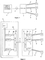
- Figure 2 illustrates the principle of the method disclosed in the publication FI-111,898 , according to which all electronics of the RDSLAM 3 are located in the central site equipment 11, except for the essential analog parts 7 of the DSL modems.
- an auxiliary channel can be provided for each subscriber, via which each digital transceiver 8 of the central site can monitor the operation of the corresponding analog parts 7, for example automatic signal gain control, in the RDSLAM.
- Said auxiliary channel is realized by multiplexing the data stream in the auxiliary channel onto the information stream transmitted over the optical fiber.
- the electronics in the RDSLAM in accordance with the system disclosed in publication FI-111,898 are considerably simpler than those of a conventional RDSLAM, which offers considerable advantages for example in arranging the power supply and in taking account of a demanding installation environment.
- the drawback of the system disclosed in publication FI-111,898 is that the bit rate of the information stream to be transferred over the optical fiber is considerably higher than in a conventional RDSLAM.
- the sampling frequency of a digital-to-analog conversion must be at least twice that much, in practice slightly more, approximately 30 MHz, and the required bit accuracy of the DA conversion must be about 12 bits.
- the bit rate to be transmitted to the subscriber is of the order of 30 Mbit/s at most, and thus approximately a ten-fold bit rate must be transmitted over the optical fiber compared to this.
- the data bit rate to be transmitted over optical fiber is not crucial as such and does not affect the actual fiber costs, but the available technology has a decisive influence on the implementation and costs of the optical transmitter and receiver (fiber transceiver).
- Available technology offers inexpensive components for implementing the fiber transceiver up to a bit rate of about 1 Gbit/s, but, but when the rate exceeds 1 Gbit/s, the cost for the components will increase very steeply. Hence, the very high bit rate required on optical fiber will increase the equipment costs considerably.
- the invention relates to a method whereby the digital signal processing of the transmitter and receiver of a DSL modem, required in an RDSLAM at the fiber end of a pair cable and being an essential component in an FTTC subscriber network, which transmits a data signal over a subscriber-specific metallic twisted pair cable, is located in a distributed manner at both ends of the fiber in such a way that part of the digital signal processing takes place at the central site and part of it in the RDSLAM.
- the optical fiber transmits the digital signals passed between the signal processing element at the central site and the signal processing element in the RDSLAM in both transmission directions.
- the divider point delimiting the part of the signal processing to be carried out at the central site is selected in such a way that the bit rate to be transmitted over the fiber will be sufficiently low, but on the other hand one strives to keep the digital signal processing at the DSLAM as simple as possible.
- a new method for establishing a digital subscriber connection between a central site and a subscriber's transmission device is provided.
- the method is characterized by that which is set forth in the characterizing portion of an independent claim directed to the method.
- the digital signal processing of a DSL modem utilizing Discrete MultiTone modulation is distributed between the central site and the RDSLAM in such a way that the active electronics included in the RDSLAM is simpler and less costly than that of the prior art.
- the digital signal processing of a DSL modem utilizing QAM modulation is distributed between the central site and the RDSLAM in such a way that the active electronics included in the RDSLAM are simpler and less costly than those of the prior art.
- the invention affords substantial advantages.
- the RDSLAM equipment to be installed in the hard environment at the subscriber end of the optical fiber is less complex, comprises less digital electronic circuits and can be implemented using less expensive optical components as compared to a system of the prior art.
- the basic idea of the method of the invention is to locate the digital signal processing functions of the subscriber-specific DSL modem, said functions residing either entirely in the RDSLAM or entirely at the central site in prior art methods, in a distributed manner so that part of the digital signal processing functions of the receiver are located at the central site, part of them are located in the RDSLAM and the digital signals passed between said signal processing functions are transmitted over one or more optical fibers by multiplexing said signals from all subscribers in digital form onto an optical fiber or fibers.
- the divider point delimiting the part of the signal processing to be located at the central site is selected in such a way that the bit rate to be transmitted over the fiber will be sufficiently low, but on the other hand it is striven to keep the digital signal processing at the RDSLAM as simple as possible.
- the subscriber-specific signals 15a and 15b of the sending and receiving direction are demultiplexed and separated at the reverse end of the optical fiber in said first and second multiplexing/demultiplexing element.
- the analog parts 7 in the RDSLAM, the first transmitter part 12a and the first receiver part 12b possibly require control signals from the signal processing elements 14a and 14b of the central site and also from the processor at the central site, which monitors the operation of said parts.
- the control signals are transported over the optical fiber 2 via an auxiliary channel, which is realized by multiplexing the control signals 19 with the digital signal 15a of the sending direction onto the optical fiber.
- FIG. 4 depicts a transmission system of the prior art utilizing DMT modulation (Discrete MultiTone modulation), which is widely used in ADSL, ADSL+ and VDSL2 modems.
- DMT modulation Discrete MultiTone modulation
- the operation of the DMT transmitter 100 and DMT receiver 101 is well known to those skilled in the art (e.g. John A. C. Bingham, Multicarrier Modulation for Data Transmission: An Idea Whose Time Has Come, IEEE Communications Magazine, May 1990 ), and thus said operations will be only briefly described herein.
- N is selected to be a power of two.
- a first Fourier transformation element 104 performs an inverse discrete Fourier transformation on the first complex vector, and produces a second N-element complex vector.
- a first N-element real vector 114 is obtained from the real parts of said second N-element complex vector and it represents a discrete time domain signal sample comprising N elements.
- These N signal samples are converted into analog form in a DA converter 105, and the resultant analog signal form is transmitted after low-pass filtering to a pair cable 4.
- the analog signal comprises K carriers in the frequency domain, each carrying a certain number of data bits.
- the signal transported through the pair cable 4 is converted into a discrete time digital sample sequence signal in an AD converter 110 of the receiver 101.
- N samples are taken from the sample sequence signal, suitably phased to the starting moment of the signal form sent by the transmitter, and an N-element second real vector 115 is obtained.
- a second Fourier transformation element 109 performs a discrete Fourier transformation on the second real vector, and the result is an N-element third complex vector whose given K elements 116 ("second K set") comprise the data information passed over cable 4.
- the signal amplitude and phase distortion incurred in the cable 4 has changed the phase and amplitude of each element in the third complex vector 116.
- the phase and amplitude are corrected with an adaptive equalizer 108, after which each of the K elements are expressed as a bit set in a detector element 107, and the bit set is further converted into a serial bit stream 112 in a equalizer element 106.
- the bandwidth of signal to be transported over a subscriber cable is 12 MHz.
- the sampling frequency of the AD and DA conversion is 30 MHz.
- FIG. 5 illustrates a prior art transmission system utilizing QAM modulation (Quadrature Amplitude Modulation).
- QAM modulation Quadrature Amplitude Modulation
- the structural parts of the QAM transmitter 200 and QAM receiver 206 as well as their operation are part of the prior art (for example: John G. Proakis, Digital Communications, McGraw-Hill Book Company ), and hence these are only briefly described herein.
- a synchronous serial bit stream 201 to be transmitted is divided in transmitter 200 into sets ofN bits (N typically 1 - 10), and each bit set is expressed in symbol converter 202 as a two-dimensional symbol.
- the digital two-dimensional sample sequence signal 300 constituted by successive symbols is filtered in baseband filters (aka pulse shapers in many instances) 203, which simultaneously interpolate the two-dimensional signal obtained in such a way that the signal sampling frequency is increased.
- the real signal obtained is converted with a DA converter 205 into analog form, processed with analog filters and analog amplifiers and supplied to a metallic pair cable 4.
- the signal that has passed the pair cable 4 is converted in receiver 206 into digital sample sequence form.
- the sample sequence signal obtained is processed in demodulator 208 and in baseband filters 209, together converting the signal into a two-dimensional baseband signal 301.
- the baseband filters 209 also decimate the signal, and hence the signal sampling frequency is decreased, in practical implementations usually to symbol frequency or double symbol frequency.
- This baseband signal 301 is distorted owing to linear amplitude and phase distortions incurred in the metallic pair cable. These distortions are corrected with an adaptive equalizer 210.
- the sample sequence modified by the adaptive equalizer is processed in a detector 211, which outputs a two-dimensional symbol, corresponding to the respective transmitted symbol, from each signal sample, and further converts said symbol into corresponding serial data bits 212.
- one advantageous division principle for dividing digital signal processing functions among both ends of the optical fiber is the following.
- the divider point in the receiver is selected for example in such a way that the adaptive equalizer 210 is located at the central site and the baseband filters 209 in the RDSLAM.
- the signal 301 passed from the baseband filters to the corrector is transported over the optical fiber from the RDSLAM to the central site.
- the sample frequency of signal 301 is in practice the symbol frequency or double symbol frequency, i.e. considerably lower than the sample frequency of the AD conversion, which will considerably decrease the bit rate of the information to be transferred over the optical fiber in comparison with the prior art. Since the adaptive equalizer 210 is a complex element requiring a considerable amount of signal processing computation, a significant portion of the signal processing is still located at the central site.
- the invention can be applied to all digital modulation methods suited to subscriber cable transmission, and in the embodiments of the invention the optical fiber transmission can be arranged and the subscriber-specific signals that are transported over the optical fiber can be multiplexed onto the optical fiber in many different ways.
Landscapes
- Engineering & Computer Science (AREA)
- Computer Networks & Wireless Communication (AREA)
- Signal Processing (AREA)
- Physics & Mathematics (AREA)
- Electromagnetism (AREA)
- Optical Communication System (AREA)
- Exchange Systems With Centralized Control (AREA)
Claims (6)
- Verfahren zur Herstellung eines digitalen Teilnehmeranschlusses zwischen einer Zentralstelle (1) und einem Übertragungsgerät (5) eines Teilnehmers, aufweisend:- Übertragung eines ersten Signals in digitaler Form durch eine Lichtfaser (2) von der Zentralstelle zu einer Einrichtung (3),- Umwandlung des ersten Signals in eine analoge Form in der Einrichtung- Übertragung des ersten Signals in analoger Form durch ein paarverseiltes Kabel (4) von der Einrichtung zum Übertragungsgerät des Teilnehmers- Übertragung eines zweiten Signals in analoger Form durch das paarverseilte Kabel von dem Übertragungsgerät des Teilnehmers zur Einrichtung- Umwandlung des zweiten Signals in eine digitale Form in der Einrichtung und- Übertragung des zweiten Signals in digitaler Form durch die Lichtfaser von der Einrichtung zur Zentralstelle,
dadurch gekennzeichnet, dass ein digitales Teilnehmerleitungsmodem (12, 14) in der Zentralstelle und in der Einrichtung verteilt angeordnet ist, so dass beim Verfahren:- ein erster Senderteil (12a) des digitalen Teilnehmerleitungsmodems in der Einrichtung zur digitalen Signalverarbeitung des ersten Signals verwendet wird- ein zweiter Senderteil (14a) des digitalen Teilnehmerleitungsmodems in der Zentralstelle zur digitalen Signalverarbeitung des ersten Signals verwendet wird- ein erster Empfängerteil (12b) des digitalen Teilnehmerleitungsmodems in der Einrichtung zur digitalen Signalverarbeitung des zweiten Signals verwendet wird- ein zweiter Empfängerteil (14b) des digitalen Teilnehmerleitungsmodems in der Zentralstelle zur digitalen Signalverarbeitung des zweiten Signals verwendet wird- analoge Teile (7) des digitalen Teilnehmerleitungsmodems in der Einrichtung zur analogen Signalverarbeitung des ersten Signals und zur analogen Signalverarbeitung des zweiten Signals verwendet werden. - Verfahren nach Anspruch 1, wobei Steuerbefehle zur Steuerung der analogen Teile des digitalen Teilnehmerleitungsmodems an der Zentralstelle festgelegt werden und die Steuerbefehle über die in das erste Signal gemultiplexte Lichtfaser übertragen werden.
- Verfahren nach Anspruch 1, wobei Steuerbefehle zur Steuerung des ersten Senderteils des digitalen Teilnehmerleitungsmodems und zur Steuerung des ersten Empfängerteils des digitalen Teilnehmerleitungsmodems an der Zentralstelle festgelegt werden und die Steuerbefehle über die in das erste Signal gemultiplexte Lichtfaser übertragen werden.
- System zur Herstellung eines digitalen Teilnehmeranschlusses zwischen einer Zentralstelle (1) und einem Übertragungsgerät (5) eines Teilnehmers, aufweisend:- eine Lichtfaser (2) zwischen der Zentralstelle und einer Einrichtung (3), wobei die Zentralstelle fähig ist, ein erstes Signal in digitaler Form der Lichtfaser zu übertragen und ein zweites Signal in digitaler Form von der Lichtfaser zu empfangen- ein paarverseiltes Kabel (4) zwischen der Einrichtung und dem Übertragungsgerät des Teilnehmers, wobei die Einrichtung fähig ist, das erste Signal in digitaler Form von der Lichtfaser zu empfangen, das erste Signal in eine analoge Form umzuwandeln, das erste Signal in analoger Form dem paarverseilten Kabel zu übertragen, das zweite Signal in analoger Form von dem paarverseilten Kabel zu empfangen, das zweite Signal in eine digitale Form umzuwandeln und das zweite Signal in digitaler Form der Lichtfaser zu übertragen,
dadurch gekennzeichnet, dass ein digitales Teilnehmerleitungsmodem (12, 14) in der Zentralstelle und in der Einrichtung verteilt angeordnet ist, so dass:- die Einrichtung einen ersten Senderteil (12a) des digitalen Teilnehmerleitungsmodems zur digitalen Signalverarbeitung des ersten Signals umfasst- die Zentralstelle einen zweiten Senderteil (14a) des digitalen Teilnehmerleitungsmodems zur digitalen Signalverarbeitung des ersten Signals umfasst- die Einrichtung einen ersten Empfängerteil (12b) des digitalen Teilnehmerleitungsmodems zur digitalen Signalverarbeitung des zweiten Signals umfasst- die Zentralstelle einen zweiten Empfängerteil (14b) des digitalen Teilnehmerleitungsmodems zur digitalen Signalverarbeitung des zweiten Signals umfasst und- die Einrichtung analoge Teile (7) des digitalen Teilnehmerleitungsmodems zur analogen Signalverarbeitung des ersten Signals und zur analogen Signalverarbeitung des zweiten Signals umfasst. - System nach Anspruch 4, wobei die Zentralstelle aufweist: Mittel zur Festlegung von Steuerbefehlen, um die analogen Teile des digitalen Teilnehmerleitungsmodems zu steuern, und Mittel zur Übertragung der Steuerbefehle über die in das erste Signal gemultiplexte Lichtfaser.
- System nach Anspruch 4, wobei die Zentralstelle aufweist: Mittel zur Festlegung von Steuerbefehlen, um den ersten Senderteil des digitalen Teilnehmerleitungsmodems zu steuern und den ersten Empfängerteil des digitalen Teilnehmerleitungsmodems zu steuern, und Mittel zur Übertragung der Steuerbefehle über die in das erste Signal gemultiplexte Lichtfaser.
Applications Claiming Priority (2)
| Application Number | Priority Date | Filing Date | Title |
|---|---|---|---|
| FI20050796A FI120019B (fi) | 2005-08-05 | 2005-08-05 | Menetelmä tilaajayhteyden järjestämiseksi ja menetelmää soveltava järjestelmä |
| PCT/FI2006/000270 WO2007028852A1 (en) | 2005-08-05 | 2006-08-04 | Method for establishing a subscriber connection and a system utilizing the method |
Publications (3)
| Publication Number | Publication Date |
|---|---|
| EP1941663A1 EP1941663A1 (de) | 2008-07-09 |
| EP1941663A4 EP1941663A4 (de) | 2010-11-10 |
| EP1941663B1 true EP1941663B1 (de) | 2011-11-16 |
Family
ID=34896268
Family Applications (1)
| Application Number | Title | Priority Date | Filing Date |
|---|---|---|---|
| EP06778492A Not-in-force EP1941663B1 (de) | 2005-08-05 | 2006-08-04 | Verfahren zur herstellung einer teilnehmerverbindung und das verfahren benutzendes system |
Country Status (5)
| Country | Link |
|---|---|
| US (1) | US20080166125A1 (de) |
| EP (1) | EP1941663B1 (de) |
| AT (1) | ATE534215T1 (de) |
| FI (1) | FI120019B (de) |
| WO (1) | WO2007028852A1 (de) |
Families Citing this family (2)
| Publication number | Priority date | Publication date | Assignee | Title |
|---|---|---|---|---|
| US8437299B2 (en) * | 2010-08-17 | 2013-05-07 | Qualcomm Incorporated | Radio channel aggregation and segmentation |
| GB2578269A (en) * | 2018-03-28 | 2020-05-06 | British Telecomm | Network |
Family Cites Families (18)
| Publication number | Priority date | Publication date | Assignee | Title |
|---|---|---|---|---|
| US6021167A (en) * | 1996-05-09 | 2000-02-01 | Texas Instruments Incorporated | Fast equalizer training and frame synchronization algorithms for discrete multi-tone (DMT) system |
| US5987061A (en) * | 1996-05-09 | 1999-11-16 | Texas Instruments Incorporated | Modem initialization process for line code and rate selection in DSL data communication |
| US20020133528A1 (en) * | 1996-12-30 | 2002-09-19 | Smart Link Ltd. | Modem with distributed functionality |
| US6621346B1 (en) * | 1998-03-30 | 2003-09-16 | Texas Instruments Incorporated | Impedance matching for programmable gain amplifiers |
| US6765954B1 (en) * | 1999-08-16 | 2004-07-20 | Globespanvirata, Inc. | System and method for implementing a delta-sigma modulator integrity supervisor |
| US6711138B1 (en) * | 1999-09-30 | 2004-03-23 | Conexant Systems, Inc. | Digital subscriber line/home phoneline network router |
| US6442248B1 (en) * | 2000-01-12 | 2002-08-27 | Multi-Tech Systems, Inc. | System for providing analog and digital telephone functions using a single telephone line |
| US20020031113A1 (en) * | 2000-07-07 | 2002-03-14 | Dodds David E. | Extended distribution of ADSL signals |
| AU2002223347A1 (en) * | 2000-11-30 | 2002-06-11 | Esion Networks Inc. | Apparatus for connecting digital subscriber lines to central office equipment |
| US20020064221A1 (en) * | 2000-11-30 | 2002-05-30 | Yeap Tet Hin | Apparatus for connecting digital subscriber lines to central office equipment |
| US6785384B2 (en) * | 2000-12-04 | 2004-08-31 | Agere Systems Inc. | Two-step algorithm for training an echo cancellation filter |
| EP1358731A4 (de) * | 2001-02-06 | 2005-08-24 | 2Wire Inc | "ferngespeiste schleifenerweiterungsvorrichtung mit kommunikation, steuerung und diagnose" |
| WO2002063861A1 (en) * | 2001-02-06 | 2002-08-15 | 2Wire, Inc. | Loop extender with communications, control, and diagnostics |
| US6973123B2 (en) * | 2001-03-21 | 2005-12-06 | International Business Machines Corporation | System and method for controlling line driver power in digital subscriber line modems |
| US6665497B1 (en) * | 2001-07-05 | 2003-12-16 | Cisco Technology, Inc. | Modular transceiver and accessory system for use in an optical network |
| FI111898B (fi) * | 2001-08-17 | 2003-09-30 | Heikki Tapio Laamanen | Menetelmä tilaajayhteyden järjestämiseksi ja menetelmää soveltava järjestelmä |
| EP1389029A1 (de) * | 2002-07-30 | 2004-02-11 | Alcatel | Ein DSL-Zugriffssystem, eine zentrale DSL-Abschlusseinheit und eine Fern-DSL-Abschlusseinheit zur Realisierung eines DSLAMs |
| EP1665869A1 (de) * | 2003-09-23 | 2006-06-07 | BRITISH TELECOMMUNICATIONS public limited company | Breitband-kommunikation |
-
2005
- 2005-08-05 FI FI20050796A patent/FI120019B/fi not_active IP Right Cessation
-
2006
- 2006-08-04 EP EP06778492A patent/EP1941663B1/de not_active Not-in-force
- 2006-08-04 AT AT06778492T patent/ATE534215T1/de active
- 2006-08-04 WO PCT/FI2006/000270 patent/WO2007028852A1/en not_active Ceased
-
2008
- 2008-01-29 US US12/022,130 patent/US20080166125A1/en not_active Abandoned
Also Published As
| Publication number | Publication date |
|---|---|
| EP1941663A4 (de) | 2010-11-10 |
| ATE534215T1 (de) | 2011-12-15 |
| US20080166125A1 (en) | 2008-07-10 |
| EP1941663A1 (de) | 2008-07-09 |
| FI20050796L (fi) | 2007-02-06 |
| FI120019B (fi) | 2009-05-29 |
| FI20050796A0 (fi) | 2005-08-05 |
| WO2007028852A1 (en) | 2007-03-15 |
Similar Documents
| Publication | Publication Date | Title |
|---|---|---|
| US5987061A (en) | Modem initialization process for line code and rate selection in DSL data communication | |
| US6021158A (en) | Hybrid wireless wire-line network integration and management | |
| US6038251A (en) | Direct equalization method | |
| US6285718B1 (en) | Adaptive noise canceller | |
| EP0831624A2 (de) | Ein Modem | |
| US8149970B2 (en) | Multiple input, multiple output channel, digital receiver tuner | |
| EP0806852A2 (de) | Digitales Multimode-Modem | |
| EP0820168A2 (de) | Modem mit mehreren Arbeitsmodi und Protokolle dafür | |
| US6731678B1 (en) | System and method for extending the operating range and/or increasing the bandwidth of a communication link | |
| KR19980024329A (ko) | 스플릿 모뎀 | |
| EP1109329B1 (de) | DSL-Übertragungsystem mit Fernnebensprechkompensation | |
| US20080117805A1 (en) | Method and apparatus for cross-talk cancellation in frequency division multiplexed transmission systems | |
| EP1419649B1 (de) | Verfahren zur herstellung einer teilnehmerverbindung und system mit dem verfahren | |
| EP1680876B1 (de) | Verfahren zur herstellung einer teilnehmerverbindung und das verfahren benutzendes system | |
| SE515218C2 (sv) | Anordning och förfarande vid kabelTVnät | |
| EP1941663B1 (de) | Verfahren zur herstellung einer teilnehmerverbindung und das verfahren benutzendes system | |
| US7076002B1 (en) | Method and apparatus for symbol boundary synchronization | |
| EP1061689A2 (de) | Verringerung der durch Intermodulationsprodukte verursachten Interferenz in Mehrträgrzesendern/-Empfängern | |
| US8279859B2 (en) | Method and arrangement for transferring synchronizing information | |
| US8787144B2 (en) | Interleaved signaling | |
| Spruyt et al. | VDSL, from concept to chips | |
| Langston | Local Multipoint Distribution Services (LMDS) system concepts and implementation | |
| AU756231B2 (en) | Communication line terminating unit, modem and central office unit wherein the line terminating unit is used | |
| JP4025184B2 (ja) | 加入者系光ファイバ伝送システム | |
| US20060039512A1 (en) | Large scale integrated circuit for data communication, data communication apparatus, data communication system and data communication method |
Legal Events
| Date | Code | Title | Description |
|---|---|---|---|
| PUAI | Public reference made under article 153(3) epc to a published international application that has entered the european phase |
Free format text: ORIGINAL CODE: 0009012 |
|
| 17P | Request for examination filed |
Effective date: 20080304 |
|
| AK | Designated contracting states |
Kind code of ref document: A1 Designated state(s): AT BE BG CH CY CZ DE DK EE ES FI FR GB GR HU IE IS IT LI LT LU LV MC NL PL PT RO SE SI SK TR |
|
| A4 | Supplementary search report drawn up and despatched |
Effective date: 20101012 |
|
| GRAP | Despatch of communication of intention to grant a patent |
Free format text: ORIGINAL CODE: EPIDOSNIGR1 |
|
| GRAC | Information related to communication of intention to grant a patent modified |
Free format text: ORIGINAL CODE: EPIDOSCIGR1 |
|
| RIC1 | Information provided on ipc code assigned before grant |
Ipc: H04B 10/207 20060101ALI20110505BHEP Ipc: H04L 12/28 20060101AFI20110505BHEP Ipc: H04M 11/06 20060101ALI20110505BHEP Ipc: H04Q 11/04 20060101ALI20110505BHEP |
|
| DAX | Request for extension of the european patent (deleted) | ||
| GRAS | Grant fee paid |
Free format text: ORIGINAL CODE: EPIDOSNIGR3 |
|
| GRAA | (expected) grant |
Free format text: ORIGINAL CODE: 0009210 |
|
| AK | Designated contracting states |
Kind code of ref document: B1 Designated state(s): AT BE BG CH CY CZ DE DK EE ES FI FR GB GR HU IE IS IT LI LT LU LV MC NL PL PT RO SE SI SK TR |
|
| RAP1 | Party data changed (applicant data changed or rights of an application transferred) |
Owner name: LAAMANEN, HEIKKI |
|
| REG | Reference to a national code |
Ref country code: GB Ref legal event code: FG4D |
|
| RIN1 | Information on inventor provided before grant (corrected) |
Inventor name: LAAMANEN, HEIKKI |
|
| REG | Reference to a national code |
Ref country code: CH Ref legal event code: EP |
|
| REG | Reference to a national code |
Ref country code: IE Ref legal event code: FG4D |
|
| REG | Reference to a national code |
Ref country code: DE Ref legal event code: R096 Ref document number: 602006025882 Country of ref document: DE Effective date: 20120126 |
|
| REG | Reference to a national code |
Ref country code: NL Ref legal event code: VDEP Effective date: 20111116 |
|
| LTIE | Lt: invalidation of european patent or patent extension |
Effective date: 20111116 |
|
| PG25 | Lapsed in a contracting state [announced via postgrant information from national office to epo] |
Ref country code: LT Free format text: LAPSE BECAUSE OF FAILURE TO SUBMIT A TRANSLATION OF THE DESCRIPTION OR TO PAY THE FEE WITHIN THE PRESCRIBED TIME-LIMIT Effective date: 20111116 Ref country code: IS Free format text: LAPSE BECAUSE OF FAILURE TO SUBMIT A TRANSLATION OF THE DESCRIPTION OR TO PAY THE FEE WITHIN THE PRESCRIBED TIME-LIMIT Effective date: 20120316 |
|
| PG25 | Lapsed in a contracting state [announced via postgrant information from national office to epo] |
Ref country code: GR Free format text: LAPSE BECAUSE OF FAILURE TO SUBMIT A TRANSLATION OF THE DESCRIPTION OR TO PAY THE FEE WITHIN THE PRESCRIBED TIME-LIMIT Effective date: 20120217 Ref country code: SE Free format text: LAPSE BECAUSE OF FAILURE TO SUBMIT A TRANSLATION OF THE DESCRIPTION OR TO PAY THE FEE WITHIN THE PRESCRIBED TIME-LIMIT Effective date: 20111116 Ref country code: PT Free format text: LAPSE BECAUSE OF FAILURE TO SUBMIT A TRANSLATION OF THE DESCRIPTION OR TO PAY THE FEE WITHIN THE PRESCRIBED TIME-LIMIT Effective date: 20120316 Ref country code: NL Free format text: LAPSE BECAUSE OF FAILURE TO SUBMIT A TRANSLATION OF THE DESCRIPTION OR TO PAY THE FEE WITHIN THE PRESCRIBED TIME-LIMIT Effective date: 20111116 Ref country code: BE Free format text: LAPSE BECAUSE OF FAILURE TO SUBMIT A TRANSLATION OF THE DESCRIPTION OR TO PAY THE FEE WITHIN THE PRESCRIBED TIME-LIMIT Effective date: 20111116 Ref country code: PL Free format text: LAPSE BECAUSE OF FAILURE TO SUBMIT A TRANSLATION OF THE DESCRIPTION OR TO PAY THE FEE WITHIN THE PRESCRIBED TIME-LIMIT Effective date: 20111116 Ref country code: SI Free format text: LAPSE BECAUSE OF FAILURE TO SUBMIT A TRANSLATION OF THE DESCRIPTION OR TO PAY THE FEE WITHIN THE PRESCRIBED TIME-LIMIT Effective date: 20111116 Ref country code: LV Free format text: LAPSE BECAUSE OF FAILURE TO SUBMIT A TRANSLATION OF THE DESCRIPTION OR TO PAY THE FEE WITHIN THE PRESCRIBED TIME-LIMIT Effective date: 20111116 |
|
| PG25 | Lapsed in a contracting state [announced via postgrant information from national office to epo] |
Ref country code: CY Free format text: LAPSE BECAUSE OF FAILURE TO SUBMIT A TRANSLATION OF THE DESCRIPTION OR TO PAY THE FEE WITHIN THE PRESCRIBED TIME-LIMIT Effective date: 20111116 |
|
| PG25 | Lapsed in a contracting state [announced via postgrant information from national office to epo] |
Ref country code: SK Free format text: LAPSE BECAUSE OF FAILURE TO SUBMIT A TRANSLATION OF THE DESCRIPTION OR TO PAY THE FEE WITHIN THE PRESCRIBED TIME-LIMIT Effective date: 20111116 Ref country code: DK Free format text: LAPSE BECAUSE OF FAILURE TO SUBMIT A TRANSLATION OF THE DESCRIPTION OR TO PAY THE FEE WITHIN THE PRESCRIBED TIME-LIMIT Effective date: 20111116 Ref country code: CZ Free format text: LAPSE BECAUSE OF FAILURE TO SUBMIT A TRANSLATION OF THE DESCRIPTION OR TO PAY THE FEE WITHIN THE PRESCRIBED TIME-LIMIT Effective date: 20111116 Ref country code: BG Free format text: LAPSE BECAUSE OF FAILURE TO SUBMIT A TRANSLATION OF THE DESCRIPTION OR TO PAY THE FEE WITHIN THE PRESCRIBED TIME-LIMIT Effective date: 20120216 Ref country code: EE Free format text: LAPSE BECAUSE OF FAILURE TO SUBMIT A TRANSLATION OF THE DESCRIPTION OR TO PAY THE FEE WITHIN THE PRESCRIBED TIME-LIMIT Effective date: 20111116 |
|
| PG25 | Lapsed in a contracting state [announced via postgrant information from national office to epo] |
Ref country code: RO Free format text: LAPSE BECAUSE OF FAILURE TO SUBMIT A TRANSLATION OF THE DESCRIPTION OR TO PAY THE FEE WITHIN THE PRESCRIBED TIME-LIMIT Effective date: 20111116 Ref country code: IT Free format text: LAPSE BECAUSE OF FAILURE TO SUBMIT A TRANSLATION OF THE DESCRIPTION OR TO PAY THE FEE WITHIN THE PRESCRIBED TIME-LIMIT Effective date: 20111116 |
|
| REG | Reference to a national code |
Ref country code: AT Ref legal event code: MK05 Ref document number: 534215 Country of ref document: AT Kind code of ref document: T Effective date: 20111116 |
|
| PLBE | No opposition filed within time limit |
Free format text: ORIGINAL CODE: 0009261 |
|
| STAA | Information on the status of an ep patent application or granted ep patent |
Free format text: STATUS: NO OPPOSITION FILED WITHIN TIME LIMIT |
|
| 26N | No opposition filed |
Effective date: 20120817 |
|
| REG | Reference to a national code |
Ref country code: DE Ref legal event code: R097 Ref document number: 602006025882 Country of ref document: DE Effective date: 20120817 |
|
| PG25 | Lapsed in a contracting state [announced via postgrant information from national office to epo] |
Ref country code: AT Free format text: LAPSE BECAUSE OF FAILURE TO SUBMIT A TRANSLATION OF THE DESCRIPTION OR TO PAY THE FEE WITHIN THE PRESCRIBED TIME-LIMIT Effective date: 20111116 |
|
| REG | Reference to a national code |
Ref country code: CH Ref legal event code: PL |
|
| PG25 | Lapsed in a contracting state [announced via postgrant information from national office to epo] |
Ref country code: MC Free format text: LAPSE BECAUSE OF NON-PAYMENT OF DUE FEES Effective date: 20120831 |
|
| PG25 | Lapsed in a contracting state [announced via postgrant information from national office to epo] |
Ref country code: ES Free format text: LAPSE BECAUSE OF FAILURE TO SUBMIT A TRANSLATION OF THE DESCRIPTION OR TO PAY THE FEE WITHIN THE PRESCRIBED TIME-LIMIT Effective date: 20120227 Ref country code: CH Free format text: LAPSE BECAUSE OF NON-PAYMENT OF DUE FEES Effective date: 20120831 Ref country code: LI Free format text: LAPSE BECAUSE OF NON-PAYMENT OF DUE FEES Effective date: 20120831 |
|
| REG | Reference to a national code |
Ref country code: IE Ref legal event code: MM4A |
|
| PG25 | Lapsed in a contracting state [announced via postgrant information from national office to epo] |
Ref country code: FI Free format text: LAPSE BECAUSE OF FAILURE TO SUBMIT A TRANSLATION OF THE DESCRIPTION OR TO PAY THE FEE WITHIN THE PRESCRIBED TIME-LIMIT Effective date: 20111116 |
|
| PG25 | Lapsed in a contracting state [announced via postgrant information from national office to epo] |
Ref country code: IE Free format text: LAPSE BECAUSE OF NON-PAYMENT OF DUE FEES Effective date: 20120804 |
|
| PGFP | Annual fee paid to national office [announced via postgrant information from national office to epo] |
Ref country code: DE Payment date: 20130902 Year of fee payment: 8 |
|
| PGFP | Annual fee paid to national office [announced via postgrant information from national office to epo] |
Ref country code: GB Payment date: 20130924 Year of fee payment: 8 Ref country code: FR Payment date: 20130902 Year of fee payment: 8 |
|
| PG25 | Lapsed in a contracting state [announced via postgrant information from national office to epo] |
Ref country code: TR Free format text: LAPSE BECAUSE OF FAILURE TO SUBMIT A TRANSLATION OF THE DESCRIPTION OR TO PAY THE FEE WITHIN THE PRESCRIBED TIME-LIMIT Effective date: 20111116 |
|
| PG25 | Lapsed in a contracting state [announced via postgrant information from national office to epo] |
Ref country code: LU Free format text: LAPSE BECAUSE OF NON-PAYMENT OF DUE FEES Effective date: 20120804 |
|
| PG25 | Lapsed in a contracting state [announced via postgrant information from national office to epo] |
Ref country code: HU Free format text: LAPSE BECAUSE OF FAILURE TO SUBMIT A TRANSLATION OF THE DESCRIPTION OR TO PAY THE FEE WITHIN THE PRESCRIBED TIME-LIMIT Effective date: 20060804 |
|
| REG | Reference to a national code |
Ref country code: DE Ref legal event code: R119 Ref document number: 602006025882 Country of ref document: DE |
|
| GBPC | Gb: european patent ceased through non-payment of renewal fee |
Effective date: 20140804 |
|
| REG | Reference to a national code |
Ref country code: DE Ref legal event code: R119 Ref document number: 602006025882 Country of ref document: DE Effective date: 20150303 |
|
| REG | Reference to a national code |
Ref country code: FR Ref legal event code: ST Effective date: 20150430 |
|
| PG25 | Lapsed in a contracting state [announced via postgrant information from national office to epo] |
Ref country code: DE Free format text: LAPSE BECAUSE OF NON-PAYMENT OF DUE FEES Effective date: 20150303 Ref country code: GB Free format text: LAPSE BECAUSE OF NON-PAYMENT OF DUE FEES Effective date: 20140804 |
|
| PG25 | Lapsed in a contracting state [announced via postgrant information from national office to epo] |
Ref country code: FR Free format text: LAPSE BECAUSE OF NON-PAYMENT OF DUE FEES Effective date: 20140901 |