EP1939832B1 - Capteur-émetteur de sécurité pour la détection de vent dans une installation domotique - Google Patents
Capteur-émetteur de sécurité pour la détection de vent dans une installation domotique Download PDFInfo
- Publication number
- EP1939832B1 EP1939832B1 EP07150149A EP07150149A EP1939832B1 EP 1939832 B1 EP1939832 B1 EP 1939832B1 EP 07150149 A EP07150149 A EP 07150149A EP 07150149 A EP07150149 A EP 07150149A EP 1939832 B1 EP1939832 B1 EP 1939832B1
- Authority
- EP
- European Patent Office
- Prior art keywords
- sensor
- transmitter
- state
- signal
- housing
- Prior art date
- Legal status (The legal status is an assumption and is not a legal conclusion. Google has not performed a legal analysis and makes no representation as to the accuracy of the status listed.)
- Active
Links
Images


Classifications
-
- G—PHYSICS
- G08—SIGNALLING
- G08C—TRANSMISSION SYSTEMS FOR MEASURED VALUES, CONTROL OR SIMILAR SIGNALS
- G08C17/00—Arrangements for transmitting signals characterised by the use of a wireless electrical link
- G08C17/02—Arrangements for transmitting signals characterised by the use of a wireless electrical link using a radio link
-
- E—FIXED CONSTRUCTIONS
- E04—BUILDING
- E04F—FINISHING WORK ON BUILDINGS, e.g. STAIRS, FLOORS
- E04F10/00—Sunshades, e.g. Florentine blinds or jalousies; Outside screens; Awnings or baldachins
- E04F10/02—Sunshades, e.g. Florentine blinds or jalousies; Outside screens; Awnings or baldachins of flexible canopy materials, e.g. canvas ; Baldachins
- E04F10/06—Sunshades, e.g. Florentine blinds or jalousies; Outside screens; Awnings or baldachins of flexible canopy materials, e.g. canvas ; Baldachins comprising a roller-blind with means for holding the end away from a building
- E04F10/0644—Sunshades, e.g. Florentine blinds or jalousies; Outside screens; Awnings or baldachins of flexible canopy materials, e.g. canvas ; Baldachins comprising a roller-blind with means for holding the end away from a building with mechanisms for unrolling or balancing the blind
- E04F10/0659—Control systems therefor
-
- G—PHYSICS
- G01—MEASURING; TESTING
- G01H—MEASUREMENT OF MECHANICAL VIBRATIONS OR ULTRASONIC, SONIC OR INFRASONIC WAVES
- G01H1/00—Measuring characteristics of vibrations in solids by using direct conduction to the detector
-
- G—PHYSICS
- G01—MEASURING; TESTING
- G01P—MEASURING LINEAR OR ANGULAR SPEED, ACCELERATION, DECELERATION, OR SHOCK; INDICATING PRESENCE, ABSENCE, OR DIRECTION, OF MOVEMENT
- G01P13/00—Indicating or recording presence, absence, or direction, of movement
-
- E—FIXED CONSTRUCTIONS
- E04—BUILDING
- E04F—FINISHING WORK ON BUILDINGS, e.g. STAIRS, FLOORS
- E04F10/00—Sunshades, e.g. Florentine blinds or jalousies; Outside screens; Awnings or baldachins
- E04F10/02—Sunshades, e.g. Florentine blinds or jalousies; Outside screens; Awnings or baldachins of flexible canopy materials, e.g. canvas ; Baldachins
- E04F10/06—Sunshades, e.g. Florentine blinds or jalousies; Outside screens; Awnings or baldachins of flexible canopy materials, e.g. canvas ; Baldachins comprising a roller-blind with means for holding the end away from a building
- E04F10/0611—Sunshades, e.g. Florentine blinds or jalousies; Outside screens; Awnings or baldachins of flexible canopy materials, e.g. canvas ; Baldachins comprising a roller-blind with means for holding the end away from a building with articulated arms supporting the movable end of the blind for deployment of the blind
- E04F10/0618—Sunshades, e.g. Florentine blinds or jalousies; Outside screens; Awnings or baldachins of flexible canopy materials, e.g. canvas ; Baldachins comprising a roller-blind with means for holding the end away from a building with articulated arms supporting the movable end of the blind for deployment of the blind whereby the pivot axis of the articulation is perpendicular to the roller
-
- E—FIXED CONSTRUCTIONS
- E04—BUILDING
- E04F—FINISHING WORK ON BUILDINGS, e.g. STAIRS, FLOORS
- E04F10/00—Sunshades, e.g. Florentine blinds or jalousies; Outside screens; Awnings or baldachins
- E04F10/02—Sunshades, e.g. Florentine blinds or jalousies; Outside screens; Awnings or baldachins of flexible canopy materials, e.g. canvas ; Baldachins
- E04F10/06—Sunshades, e.g. Florentine blinds or jalousies; Outside screens; Awnings or baldachins of flexible canopy materials, e.g. canvas ; Baldachins comprising a roller-blind with means for holding the end away from a building
- E04F10/0692—Front bars
-
- E—FIXED CONSTRUCTIONS
- E06—DOORS, WINDOWS, SHUTTERS, OR ROLLER BLINDS IN GENERAL; LADDERS
- E06B—FIXED OR MOVABLE CLOSURES FOR OPENINGS IN BUILDINGS, VEHICLES, FENCES OR LIKE ENCLOSURES IN GENERAL, e.g. DOORS, WINDOWS, BLINDS, GATES
- E06B9/00—Screening or protective devices for wall or similar openings, with or without operating or securing mechanisms; Closures of similar construction
- E06B9/56—Operating, guiding or securing devices or arrangements for roll-type closures; Spring drums; Tape drums; Counterweighting arrangements therefor
- E06B9/68—Operating devices or mechanisms, e.g. with electric drive
- E06B2009/6809—Control
- E06B2009/6818—Control using sensors
- E06B2009/6863—Control using sensors sensing wind speed
-
- G—PHYSICS
- G08—SIGNALLING
- G08C—TRANSMISSION SYSTEMS FOR MEASURED VALUES, CONTROL OR SIMILAR SIGNALS
- G08C2201/00—Transmission systems of control signals via wireless link
- G08C2201/50—Receiving or transmitting feedback, e.g. replies, status updates, acknowledgements, from the controlled devices
- G08C2201/51—Remote controlling of devices based on replies, status thereof
Definitions
- the invention relates to a safety sensor-transmitter disposed on a motorized mobile structure in a home automation system, in particular a motorized blind, to a method of inhibition and to a method of learning such a sensor-transmitter.
- the transmitter-sensor includes a wireless transmitter for transmitting a security signal.
- vibration sensors comprising for example an accelerometer
- the sensor is fixed against the mobile structure, in a place where the effects of the wind are particularly marked.
- It also includes a device for analyzing the signals from the accelerometer, and a radio transmitter for sending to a control unit of a motor a fallback order of the blind when the vibration level exceeds a predetermined threshold.
- the sensor is autonomous in energy, powered by a battery or a battery and a photovoltaic type panel.
- a double problem posed by this type of sensor is that of setting thresholds (to adjust the sensitivity level of the sensor) and replacing the battery.
- the senor includes a perfectly sealed housing, because the mobile structure, sensitive to the effects of wind, is also subject to weather, humidity or salt spray.
- the battery and / or the means for adjusting the threshold or thresholds are accessible only after disassembling the housing, which most often involves detaching the sensor from the structure.
- the movements caused by these operations can cause the emission of a wind detection signal, automatically causing the folding of the mobile structure.
- this automatic movement can be particularly dangerous if the sensor is placed on the load bar of a terrace awning, and the user, or the installer has deployed the awning for easier access to the bar load using a stepladder.
- the object of the invention is to provide a sensor-transmitter obviating the drawbacks mentioned above and improving the transmitter-sensors known from the prior art.
- the invention proposes a sensor-transmitter of simple structure and facilitating and making less dangerous the adjustment operations, in particular the setting operations of emission thresholds.
- the invention also relates to a method of operating such a sensor-transmitter.
- the sensor-transmitter according to the invention is defined by claim 1.
- the home automation system according to the invention is defined by claim 4.
- the figure 1 represents an installation 10 comprising a motorized terrace awning whose fabric 11 is hooked by a fastener 12 to a load bar 13.
- the fabric is wound on a motorized tube 18.
- a plurality of articulated arms 14, provided with springs, make it possible to exert a force on the load bar 13 in the direction X2 and, to a lesser extent, in the direction Y1 so as to keep the fabric stretched.
- the articulated arm 14 is connected to the load bar by a first articulation 15.
- the articulated arm comprises other articulations, in particular a second articulation 16 connecting it to the fixed structure 17 of the installation, which comprises the tube of motorized winding.
- Load bar, canvas and articulated arms constitute the mobile structure.
- the installation 10 also comprises a sensor-transmitter 20, fixed on the load bar 13.
- the sensor-transmitter 20 could be located in any location such that the wind (represented by a full arrow WND), acting on the canvas 11 causes movements of the mobile structure, in particular of the location where the sensor-transmitter is located.
- the sensor-transmitter 20 transmits a safety signal to a control unit 19.
- This control unit generates the control commands of the motorized tube. It includes a receiver radio frequency equipped with an antenna, and possibly a meteorological type sensor.
- the figure 2 details the elements included in the sensor-transmitter 20.
- the sensor-transmitter comprises a base 22 fixed on the mobile structure, and a removable portion 23 forming a cover and comprising the electronic components of the sensor-transmitter.
- the cover 23 comprises clips 24 allowing rapid attachment of the cover 23 to the base 22 in recesses 25.
- the base is rigidly attached to the load bar 13 by fastening means 26 represented by circles. It can simply be a clamping screw.
- the base also comprises a primary element 27 for detecting closure of the housing, for example a magnet, a reflective patch or a pin capable of acting on a switch.
- the base and cover form the sensor-transmitter housing.
- the sensor-transmitter 20 also comprises an electronic circuit 30.
- the components are mounted on a printed circuit 31, fixed to the cover 23 by fixing lugs 28.
- These components comprise a secondary element 32 for detecting the closure of the housing, for example a Flexible blade switch (ILS or Reed) controlled by a magnet, an optocoupler or a simple switch.
- the secondary element cooperates with the primary element, as represented by a dashed curved line, to deliver an electrical state representative of the state of closure of the housing.
- the printed circuit also supports a vibration sensor 33, for example an accelerometer or an inertial sensor ball and contact, or any motion detection device.
- a vibration sensor 33 for example an accelerometer or an inertial sensor ball and contact, or any motion detection device.
- a logic processing unit 34 for example a microcontroller, a radio transmitter 35 and its antenna, a battery 36 are also located on the printed circuit 31 of the transmitter-sensor.
- the logic processing unit 34 is powered by the battery 36, as is the vibration sensor 33 if a controlled switch 37 is closed.
- the signals from the vibration sensor 33 are transmitted to a first input ACC of the logic processing unit.
- the secondary element 32 closing the housing has its output connected to a second input CLS of the logic processing unit. This input is in the low logical state as long as the enclosure is closed.
- the signals from the vibration sensor are processed, and if they exceed one or more predetermined threshold (s), then a control signal is transmitted from a first SGNL output of the logic processing unit to a RFI input of the radio transmitter 35, an output RFO feeds a radio frequency antenna, and which then emits a safety signal "wind".
- the primary and secondary elements detect not the opening of the housing but its attachment to a predetermined location of the mobile structure.
- a magnet serves as a primary element and is disposed at a point of the mobile structure
- a Reed sensor serves as a secondary element.
- the primary element can also be constituted by a simple U-shaped ferromagnetic part arranged on the mobile structure, while the magnet and the Reed sensor are placed in the housing. When the casing is placed in the vicinity of the ferromagnetic part, it channels the magnetic flux of the magnet and sends it back to the Reed sensor.
- any primary element is likely to cooperate with any secondary element when it comes to elements of the same type.
- a controlled opening switch 37 is controlled by a muting output INH of the logic processing unit 34, which has the effect of suppressing the supply of the vibration sensor 33, and therefore any signal from the latter.
- the logic processing unit 34 can simply terminate the analysis of the signals present on its ACC input, or temporarily block the sending of a signal transmission command to the radio transmitter 35, or finally temporarily removing power from the radio transmitter 35 by a means similar to the controlled switch 37, or by using the same controlled switch 37 to cut off the power to the vibration sensor and the radio transmitter.
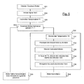
- the figure 4 represents an embodiment of the operating method according to the invention, in the form of a flow chart.
- a first step E11 it tests whether the housing is open or deposited. If this is not the case, we proceed to a second step E12, in which we test whether the wind safety threshold is reached, that is to say if the signals from the vibration sensor exceed a predetermined threshold. If the threshold is not reached, we loop on the first step E11. A sleep of 1 to 2 seconds can advantageously be inserted before returning to the first step E11.
- the security threshold If the security threshold is reached or exceeded, it goes to a third step E13 in which the sensor-transmitter emits a safety signal, or alternatively a control signal folding blind. The process then loops on the first step E11. The first three steps together constitute the monitoring mode. It is said that the transmitter sensor is in an operational state.
- a fourth step E14 is adopted in which the sensor-transmitter or, more exactly, its emission of wind or fallback safety signals is inhibited. of the awning.
- the sensor-transmitter will not transmit radio information on the presence of wind, even if the sensor-transmitter undergoes significant movements.
- the inhibition of the wind safety signal is caused for example by a power failure of the vibration sensor. As noted above, other simple means can cause inhibition. It is said that the sensor-transmitter is in an inhibited state.
- the transmitter-sensor goes into low power mode.
- This low power mode includes a regular alarm, for example every 15 minutes, with transmission of a presence signal.
- the control unit 19 automatically causes the blind to fold if it finds an anomaly in the operation of the sensor-transmitter 20, for example the non-reception of a presence signal. It is not necessary that the opening of the sensor-emitter box lead to this withdrawal, both because of the movements of the sensor-transmitter caused by its opening or its removal only because of a cessation of the emission of this presence signal.
- the step E13 comprises the transmission of a specific signal addressed to the control unit 19 to signal an intervention on the sensor-transmitter.
- the control unit then suppresses listening to the heartbeat.
- the sensor-transmitter can therefore suppress the emissions of a presence signal in the low-power mode, provided that there is transmission of a specific signal.
- the opening of the housing and / or its removal can be detected by a change of state of the second CLS input of the logic processing unit.
- This change of state causes, for example, an interruption of the microcontroller included in the logic processing unit.
- a sixth step E16 represented by a dashed block, and repeating step E11 after it has been detected that the security threshold is reached, prevents an inadvertent folding of the blind. Indeed, as soon as the user or the installer begins to manipulate the sensor-transmitter to remove it or to open its case, there is a risk that it detects vibrations that would be interpreted as due to the presence of wind and which would cause the issuance of a fallback command signal.
- the sixth step E16 is advantageously preceded by a delay T0, for example of duration one second, so as to avoid such a risk.
- the figure 5 describes a learning method according to the invention.
- the first step E21 of the learning method is similar to step E12 of the operating method.
- the second step E22 of the learning method is similar to step E14 of the operating method.
- a first timer T1 is engaged. This delay has a short duration, for example between 2 and 10 seconds.
- a fourth step E24 it is tested whether the removal and / or opening of the housing, detected in the first step E21, is maintained for the duration of the first time delay. If so, the process proceeds to a fifth step E25 of setting in low power mode. This step is identical to step E15 previously described.
- An installer who wishes to adjust the sensitivity thresholds of the sensor-transmitter must therefore perform a very simple operation: remove the sensor-transmitter housing from its support, and replace it after a few seconds. This operation is performed while the blind is deployed, at least partially.
- the entry into the adjustment step can be confirmed to the installer by a sensory signal: for example a beep emitted by the sensor-transmitter, or, preferably by the control unit 19 after it has received a radio message from the sensor-transmitter informing him of the entry into the adjustment step.
- a sensory signal for example a beep emitted by the sensor-transmitter, or, preferably by the control unit 19 after it has received a radio message from the sensor-transmitter informing him of the entry into the adjustment step.
- the adjustment step comprises five sub-steps.
- a second timer T2 is engaged. This delay has a longer duration than the previous one, for example between 30 seconds and 3 minutes.
- the installer manually causes a shake of the store representative of the effects of the wind, which constitutes a second substep E32.
- a blind is able to withstand gusts of wind quite violent, but the agitation of the structure gives a disturbing perception to the user. It is therefore desirable that the installer gives the blind a stirring movement corresponding to what seems worrying to the user, and not what could really support the blind.
- a third substep E33 the vibratory parameters picked up by the vibration sensor are measured and recorded. This substep takes place for the duration of the second timer.
- a fourth substep E34 is entered, in which the wind detection threshold, or the wind detection thresholds, are determined as a function of the measurements made and according to algorithms. or rules of thumb.
- a threshold is determined from the highest value measured, or from the average of the ten highest values. Or a first threshold is determined for a high oscillation frequency (or for a pulse regime), while a second threshold is determined for a low oscillation frequency.
- the threshold is recorded, or the thresholds are stored in a nonvolatile memory MEM contained in the logic processing unit 34.
- the adjustment step is therefore complete.
- An optional signaling sub-step may signal to the installer the end of the adjustment.
- the method then proceeds to the execution of a monitoring mode, represented by the last step E40: the sensor-transmitter being set, it is operational.
- the same opening detection of a sensor-transmitter housing designed according to the teachings of the invention allows in one case the simple inhibition of wind detection signals generated by this sensor-transmitter, and, in a another case, an extremely simple setting mode of the installation.
- Inhibiting the taking into account of wind detection signals can take several forms. In the simplest case, this inhibition results in a prohibition to transmit the safety signal. Alternatively, the transmission of the safety signal is not prohibited but a second signal is emitted, indicating the inhibited state of the sensor, as soon as the sensor goes into the inhibited state. The control unit 19 is then informed that it must no longer take into account the security signal, which has become invalid. The second signal is an invalidation signal.
- the invention has been described in the case where the sensor-transmitter housing comprises a base and a cover, the electronic circuit being secured to the cover.
- the electronic circuit is disposed on the base, while the magnet is disposed on the cover.
- the invention also applies if the housing comprising the sensor remains completely closed, which is all the more interesting to ensure sealing.
- a battery serving as sensor supply lasts more than ten years, which allows such a hermetically sealed structure.
Landscapes
- Engineering & Computer Science (AREA)
- Architecture (AREA)
- Physics & Mathematics (AREA)
- General Physics & Mathematics (AREA)
- Civil Engineering (AREA)
- Structural Engineering (AREA)
- Computer Networks & Wireless Communication (AREA)
- Burglar Alarm Systems (AREA)
- Arrangements For Transmission Of Measured Signals (AREA)
- Operating, Guiding And Securing Of Roll- Type Closing Members (AREA)
- Selective Calling Equipment (AREA)
- Alarm Systems (AREA)
- Measurement Of Mechanical Vibrations Or Ultrasonic Waves (AREA)
- Geophysics And Detection Of Objects (AREA)
- Measurement Of Velocity Or Position Using Acoustic Or Ultrasonic Waves (AREA)
- Building Awnings And Sunshades (AREA)
Applications Claiming Priority (1)
| Application Number | Priority Date | Filing Date | Title |
|---|---|---|---|
| FR0611370A FR2910677B1 (fr) | 2006-12-26 | 2006-12-26 | Capteur-emetteur de securite pour la detection de vent dans une installation domotique |
Publications (2)
| Publication Number | Publication Date |
|---|---|
| EP1939832A1 EP1939832A1 (fr) | 2008-07-02 |
| EP1939832B1 true EP1939832B1 (fr) | 2011-02-09 |
Family
ID=38227790
Family Applications (1)
| Application Number | Title | Priority Date | Filing Date |
|---|---|---|---|
| EP07150149A Active EP1939832B1 (fr) | 2006-12-26 | 2007-12-19 | Capteur-émetteur de sécurité pour la détection de vent dans une installation domotique |
Country Status (11)
| Country | Link |
|---|---|
| US (1) | US7729807B2 (enExample) |
| EP (1) | EP1939832B1 (enExample) |
| JP (1) | JP2008167439A (enExample) |
| CN (1) | CN101211499B (enExample) |
| AT (1) | ATE498170T1 (enExample) |
| AU (1) | AU2007249157B2 (enExample) |
| CA (1) | CA2616027C (enExample) |
| DE (1) | DE602007012409D1 (enExample) |
| ES (1) | ES2359892T3 (enExample) |
| FR (1) | FR2910677B1 (enExample) |
| MX (1) | MX2007016389A (enExample) |
Cited By (1)
| Publication number | Priority date | Publication date | Assignee | Title |
|---|---|---|---|---|
| EP4085648B1 (fr) * | 2019-12-31 | 2023-12-20 | Somfy Activites SA | Capteur destiné à emettre un signal d'information |
Families Citing this family (14)
| Publication number | Priority date | Publication date | Assignee | Title |
|---|---|---|---|---|
| US8887785B2 (en) * | 2009-08-11 | 2014-11-18 | Carefree/Scott Fetzer Co. | Awning control with multidimensional motion sensing |
| FR2953059B1 (fr) * | 2009-11-25 | 2011-11-04 | Schneider Electric Ind Sas | Dispositif de commande a distance |
| US8955022B2 (en) * | 2010-09-15 | 2015-02-10 | Comcast Cable Communications, Llc | Securing property |
| DE102011102606A1 (de) | 2011-05-27 | 2012-11-29 | Ika-Werke Gmbh & Co. Kg | Rührgerät mit einem Rührwerkzeug und mit einem Antriebsmotor |
| US20150107788A1 (en) * | 2012-09-17 | 2015-04-23 | Qmotion Incorporated | Method and apparatus for linked horizontal drapery panels having varying characteristics to be moved independently by a common drive system |
| US9371678B2 (en) | 2013-09-13 | 2016-06-21 | The Chamberlain Group, Inc. | Barrier operator strain detection |
| US10939155B2 (en) | 2013-11-19 | 2021-03-02 | Comcast Cable Communications, Llc | Premises automation control |
| JP6705961B2 (ja) * | 2014-08-22 | 2020-06-03 | オプテックス株式会社 | 自動開閉扉の監視装置 |
| US10012766B2 (en) | 2015-04-10 | 2018-07-03 | Google Llc | Monitoring external vibration sources for data collection |
| US10100814B1 (en) | 2015-07-08 | 2018-10-16 | Dometic Sweden Ab | Energy harvesting wind sensor |
| US10612301B2 (en) * | 2017-07-24 | 2020-04-07 | Crestron Electronics, Inc. | System and method for leveling a motorized window treatment |
| US11396772B2 (en) | 2019-12-10 | 2022-07-26 | Crestron Electronics, Inc. | Obstacle and pulling detection in a clutch based roller shade |
| US12123457B2 (en) | 2020-06-03 | 2024-10-22 | Current Products Company, LLC | Splice connector system for architectural covering support rods |
| DE102023136882A1 (de) | 2023-12-29 | 2025-07-03 | Delta Dore Rademacher Gmbh | Verfahren zum Betreiben einer Sensoreinheit zur Bestimmung des Einflusses von Wind auf eine Beschattungseinrichtung, insbesondere eine Markise |
Family Cites Families (14)
| Publication number | Priority date | Publication date | Assignee | Title |
|---|---|---|---|---|
| JPS60200575A (ja) | 1984-03-24 | 1985-10-11 | Oki Electric Ind Co Ltd | シヨツトキ半導体装置及びその製造方法 |
| JPH0554269A (ja) | 1991-08-27 | 1993-03-05 | Matsushita Electric Works Ltd | 2重タンパー機能付ワイヤレス送信器 |
| JPH10210565A (ja) * | 1997-01-28 | 1998-08-07 | Matsushita Electric Works Ltd | センサリモコンによる制御装置 |
| SE510081C2 (sv) | 1998-01-19 | 1999-04-19 | Combitech Traffic Syst Ab | Sändar- och mottagarutrustning företrädesvis för placering i fordon |
| US6441719B1 (en) * | 1998-02-13 | 2002-08-27 | Philip Y. W. Tsui | Remote signaling device for a rolling code security system |
| US6484069B2 (en) * | 2000-01-31 | 2002-11-19 | Turnils Ab | Awning assembly and control system |
| EP1122378A1 (en) * | 2000-01-31 | 2001-08-08 | Turnils AB | Awning assembly and control system |
| FR2811431B1 (fr) * | 2000-07-07 | 2002-10-11 | Somfy | Dispositif de detection de mouvement et dispositif de securite pour store a bras |
| FR2828319B1 (fr) | 2001-08-06 | 2006-07-28 | Somfy | Perfectionnement pour telecommande a changement de mode de fonctionnement |
| US6798158B2 (en) * | 2002-10-22 | 2004-09-28 | Dometic Corporation | Wind sensing awning control |
| US7123144B2 (en) * | 2003-04-23 | 2006-10-17 | Miller Edge, Inc. | Monitored transmitter and receiver system and method for safety devices |
| ATE513975T1 (de) * | 2004-04-09 | 2011-07-15 | Somfy Sas | Betriebsverfahren für einen motorisierten rollladen und vorrichtung für dessen ausführung |
| ATE491857T1 (de) | 2004-05-20 | 2011-01-15 | Yorkshire Technology Ltd | System zur erkennung von hindernissen |
| FR2910506B1 (fr) * | 2006-12-26 | 2009-02-27 | Somfy Sas | Procede de reglage d'un seuil de securite au-dela duquel un store doit etre enroule |
-
2006
- 2006-12-26 FR FR0611370A patent/FR2910677B1/fr not_active Expired - Fee Related
-
2007
- 2007-12-18 MX MX2007016389A patent/MX2007016389A/es active IP Right Grant
- 2007-12-18 US US11/958,545 patent/US7729807B2/en active Active
- 2007-12-19 DE DE602007012409T patent/DE602007012409D1/de active Active
- 2007-12-19 AT AT07150149T patent/ATE498170T1/de not_active IP Right Cessation
- 2007-12-19 EP EP07150149A patent/EP1939832B1/fr active Active
- 2007-12-19 ES ES07150149T patent/ES2359892T3/es active Active
- 2007-12-20 AU AU2007249157A patent/AU2007249157B2/en active Active
- 2007-12-21 CA CA2616027A patent/CA2616027C/en active Active
- 2007-12-26 CN CN2007103054018A patent/CN101211499B/zh active Active
- 2007-12-26 JP JP2007333986A patent/JP2008167439A/ja active Pending
Cited By (1)
| Publication number | Priority date | Publication date | Assignee | Title |
|---|---|---|---|---|
| EP4085648B1 (fr) * | 2019-12-31 | 2023-12-20 | Somfy Activites SA | Capteur destiné à emettre un signal d'information |
Also Published As
| Publication number | Publication date |
|---|---|
| FR2910677A1 (fr) | 2008-06-27 |
| AU2007249157A1 (en) | 2008-07-10 |
| JP2008167439A (ja) | 2008-07-17 |
| CN101211499A (zh) | 2008-07-02 |
| ATE498170T1 (de) | 2011-02-15 |
| CN101211499B (zh) | 2011-12-28 |
| US7729807B2 (en) | 2010-06-01 |
| FR2910677B1 (fr) | 2009-02-27 |
| CA2616027A1 (en) | 2008-06-26 |
| ES2359892T3 (es) | 2011-05-27 |
| MX2007016389A (es) | 2009-02-23 |
| CA2616027C (en) | 2015-02-03 |
| AU2007249157B2 (en) | 2012-07-12 |
| US20080150717A1 (en) | 2008-06-26 |
| EP1939832A1 (fr) | 2008-07-02 |
| DE602007012409D1 (de) | 2011-03-24 |
Similar Documents
| Publication | Publication Date | Title |
|---|---|---|
| EP1939832B1 (fr) | Capteur-émetteur de sécurité pour la détection de vent dans une installation domotique | |
| EP1939373B1 (fr) | Procédé de réglage d'un seuil de sécurité au-delà duquel un store doit être enroulé | |
| EP1659252B1 (fr) | Procédé de fonctionnement d'un dispositif motorisé de fermeture et dispositif motorisé de fermeture comprenant des moyens matériels et logiciels pour la mise en oeuvre de ce procédé | |
| EP0522949A1 (fr) | Détecteur de proximité | |
| EP0918309B1 (fr) | Système de verrouillage pour véhicule automobile équipé d'un système de détection de l'approche d'un utilisateur | |
| EP2067922B1 (fr) | Système de rideau roulant | |
| CH701707B1 (fr) | Procédé de fonctionnement d'un système de commande d'un moteur électrique d'un actionneur de store. | |
| EP2495623A1 (fr) | Procédé de détection d'une défaillance d'une sonde de température | |
| EP2060697B1 (fr) | Procédé de fonctionnement d'un actionneur électromécanique pour store à bras. | |
| EP3367184B1 (fr) | Procédé de configuration d'un capteur domotique et capteur domotique mettant en oeuvre un tel procédé | |
| EP1405280B1 (fr) | Fermeture centralisee de securite | |
| EP2093372B1 (fr) | Procédé de fonctionnement d'une unité de commande d'un actionneur électromécanique de manoeuvre d'un écran mobile | |
| EP1712882B1 (fr) | Capteur domotique autonome et installation comprenant un tel capteur | |
| EP1487076B1 (fr) | Procédé et dispositif de commande d'un volet motorisé | |
| FR3094027A1 (fr) | Dispositif connecté d’actionnement d’un système de fermeture d’une fenêtre ou d’une porte | |
| FR2822883A1 (fr) | Volet roulant motorise avec dispositif de detection d'obstacle | |
| EP1793353B1 (fr) | Procédé de détection au démarrage pour un capteur de mouvements et dispositif pour la mise en oeuvre de ce procédé | |
| FR3059783A1 (fr) | Procede de fabrication d'un capteur de mesure pour un disjoncteur | |
| FR2962837A1 (fr) | Systeme antivol pour panneau solaire | |
| FR2790557A1 (fr) | Procede et dispositif de detection et de mesure automatique de pollution dans l'atmosphere, et equipement automobile mettant en oeuvre le procede | |
| EP1487075B1 (fr) | Procédé et dispositif de commande d'un volet motorisé | |
| FR2888688A1 (fr) | Procede de communication entre un capteur domotique et un dispositif domotique destine au controle du confort visuel ou thermique dans un batiment | |
| FR2931981A1 (fr) | Dispositif d'alarme avec autotest | |
| FR2709831A1 (fr) | Système de détection de crash pour véhicule, notamment pour aéronef. |
Legal Events
| Date | Code | Title | Description |
|---|---|---|---|
| PUAI | Public reference made under article 153(3) epc to a published international application that has entered the european phase |
Free format text: ORIGINAL CODE: 0009012 |
|
| AK | Designated contracting states |
Kind code of ref document: A1 Designated state(s): AT BE BG CH CY CZ DE DK EE ES FI FR GB GR HU IE IS IT LI LT LU LV MC MT NL PL PT RO SE SI SK TR |
|
| AX | Request for extension of the european patent |
Extension state: AL BA HR MK RS |
|
| 17P | Request for examination filed |
Effective date: 20081215 |
|
| AKX | Designation fees paid |
Designated state(s): AT BE BG CH CY CZ DE DK EE ES FI FR GB GR HU IE IS IT LI LT LU LV MC MT NL PL PT RO SE SI SK TR |
|
| 17Q | First examination report despatched |
Effective date: 20090311 |
|
| GRAP | Despatch of communication of intention to grant a patent |
Free format text: ORIGINAL CODE: EPIDOSNIGR1 |
|
| GRAS | Grant fee paid |
Free format text: ORIGINAL CODE: EPIDOSNIGR3 |
|
| GRAA | (expected) grant |
Free format text: ORIGINAL CODE: 0009210 |
|
| AK | Designated contracting states |
Kind code of ref document: B1 Designated state(s): AT BE BG CH CY CZ DE DK EE ES FI FR GB GR HU IE IS IT LI LT LU LV MC MT NL PL PT RO SE SI SK TR |
|
| REG | Reference to a national code |
Ref country code: GB Ref legal event code: FG4D Free format text: NOT ENGLISH |
|
| REG | Reference to a national code |
Ref country code: CH Ref legal event code: EP |
|
| REG | Reference to a national code |
Ref country code: IE Ref legal event code: FG4D Free format text: LANGUAGE OF EP DOCUMENT: FRENCH |
|
| REG | Reference to a national code |
Ref country code: CH Ref legal event code: NV Representative=s name: BUGNION S.A. |
|
| REF | Corresponds to: |
Ref document number: 602007012409 Country of ref document: DE Date of ref document: 20110324 Kind code of ref document: P |
|
| REG | Reference to a national code |
Ref country code: DE Ref legal event code: R096 Ref document number: 602007012409 Country of ref document: DE Effective date: 20110324 |
|
| REG | Reference to a national code |
Ref country code: NL Ref legal event code: T3 |
|
| REG | Reference to a national code |
Ref country code: ES Ref legal event code: FG2A Ref document number: 2359892 Country of ref document: ES Kind code of ref document: T3 Effective date: 20110527 |
|
| REG | Reference to a national code |
Ref country code: GR Ref legal event code: EP Ref document number: 20110400798 Country of ref document: GR Effective date: 20110513 |
|
| LTIE | Lt: invalidation of european patent or patent extension |
Effective date: 20110209 |
|
| PG25 | Lapsed in a contracting state [announced via postgrant information from national office to epo] |
Ref country code: PT Free format text: LAPSE BECAUSE OF FAILURE TO SUBMIT A TRANSLATION OF THE DESCRIPTION OR TO PAY THE FEE WITHIN THE PRESCRIBED TIME-LIMIT Effective date: 20110609 Ref country code: LT Free format text: LAPSE BECAUSE OF FAILURE TO SUBMIT A TRANSLATION OF THE DESCRIPTION OR TO PAY THE FEE WITHIN THE PRESCRIBED TIME-LIMIT Effective date: 20110209 Ref country code: SE Free format text: LAPSE BECAUSE OF FAILURE TO SUBMIT A TRANSLATION OF THE DESCRIPTION OR TO PAY THE FEE WITHIN THE PRESCRIBED TIME-LIMIT Effective date: 20110209 Ref country code: LV Free format text: LAPSE BECAUSE OF FAILURE TO SUBMIT A TRANSLATION OF THE DESCRIPTION OR TO PAY THE FEE WITHIN THE PRESCRIBED TIME-LIMIT Effective date: 20110209 |
|
| PG25 | Lapsed in a contracting state [announced via postgrant information from national office to epo] |
Ref country code: BG Free format text: LAPSE BECAUSE OF FAILURE TO SUBMIT A TRANSLATION OF THE DESCRIPTION OR TO PAY THE FEE WITHIN THE PRESCRIBED TIME-LIMIT Effective date: 20110509 Ref country code: AT Free format text: LAPSE BECAUSE OF FAILURE TO SUBMIT A TRANSLATION OF THE DESCRIPTION OR TO PAY THE FEE WITHIN THE PRESCRIBED TIME-LIMIT Effective date: 20110209 Ref country code: FI Free format text: LAPSE BECAUSE OF FAILURE TO SUBMIT A TRANSLATION OF THE DESCRIPTION OR TO PAY THE FEE WITHIN THE PRESCRIBED TIME-LIMIT Effective date: 20110209 Ref country code: PL Free format text: LAPSE BECAUSE OF FAILURE TO SUBMIT A TRANSLATION OF THE DESCRIPTION OR TO PAY THE FEE WITHIN THE PRESCRIBED TIME-LIMIT Effective date: 20110209 Ref country code: CY Free format text: LAPSE BECAUSE OF FAILURE TO SUBMIT A TRANSLATION OF THE DESCRIPTION OR TO PAY THE FEE WITHIN THE PRESCRIBED TIME-LIMIT Effective date: 20110209 Ref country code: SI Free format text: LAPSE BECAUSE OF FAILURE TO SUBMIT A TRANSLATION OF THE DESCRIPTION OR TO PAY THE FEE WITHIN THE PRESCRIBED TIME-LIMIT Effective date: 20110209 |
|
| REG | Reference to a national code |
Ref country code: IE Ref legal event code: FD4D |
|
| PG25 | Lapsed in a contracting state [announced via postgrant information from national office to epo] |
Ref country code: DK Free format text: LAPSE BECAUSE OF FAILURE TO SUBMIT A TRANSLATION OF THE DESCRIPTION OR TO PAY THE FEE WITHIN THE PRESCRIBED TIME-LIMIT Effective date: 20110209 Ref country code: IE Free format text: LAPSE BECAUSE OF FAILURE TO SUBMIT A TRANSLATION OF THE DESCRIPTION OR TO PAY THE FEE WITHIN THE PRESCRIBED TIME-LIMIT Effective date: 20110209 Ref country code: EE Free format text: LAPSE BECAUSE OF FAILURE TO SUBMIT A TRANSLATION OF THE DESCRIPTION OR TO PAY THE FEE WITHIN THE PRESCRIBED TIME-LIMIT Effective date: 20110209 |
|
| PG25 | Lapsed in a contracting state [announced via postgrant information from national office to epo] |
Ref country code: RO Free format text: LAPSE BECAUSE OF FAILURE TO SUBMIT A TRANSLATION OF THE DESCRIPTION OR TO PAY THE FEE WITHIN THE PRESCRIBED TIME-LIMIT Effective date: 20110209 Ref country code: SK Free format text: LAPSE BECAUSE OF FAILURE TO SUBMIT A TRANSLATION OF THE DESCRIPTION OR TO PAY THE FEE WITHIN THE PRESCRIBED TIME-LIMIT Effective date: 20110209 Ref country code: CZ Free format text: LAPSE BECAUSE OF FAILURE TO SUBMIT A TRANSLATION OF THE DESCRIPTION OR TO PAY THE FEE WITHIN THE PRESCRIBED TIME-LIMIT Effective date: 20110209 |
|
| PLBE | No opposition filed within time limit |
Free format text: ORIGINAL CODE: 0009261 |
|
| STAA | Information on the status of an ep patent application or granted ep patent |
Free format text: STATUS: NO OPPOSITION FILED WITHIN TIME LIMIT |
|
| 26N | No opposition filed |
Effective date: 20111110 |
|
| REG | Reference to a national code |
Ref country code: DE Ref legal event code: R097 Ref document number: 602007012409 Country of ref document: DE Effective date: 20111110 |
|
| PG25 | Lapsed in a contracting state [announced via postgrant information from national office to epo] |
Ref country code: MC Free format text: LAPSE BECAUSE OF NON-PAYMENT OF DUE FEES Effective date: 20111231 |
|
| PG25 | Lapsed in a contracting state [announced via postgrant information from national office to epo] |
Ref country code: MT Free format text: LAPSE BECAUSE OF FAILURE TO SUBMIT A TRANSLATION OF THE DESCRIPTION OR TO PAY THE FEE WITHIN THE PRESCRIBED TIME-LIMIT Effective date: 20110209 |
|
| PG25 | Lapsed in a contracting state [announced via postgrant information from national office to epo] |
Ref country code: LU Free format text: LAPSE BECAUSE OF NON-PAYMENT OF DUE FEES Effective date: 20111219 |
|
| PG25 | Lapsed in a contracting state [announced via postgrant information from national office to epo] |
Ref country code: IS Free format text: LAPSE BECAUSE OF FAILURE TO SUBMIT A TRANSLATION OF THE DESCRIPTION OR TO PAY THE FEE WITHIN THE PRESCRIBED TIME-LIMIT Effective date: 20110209 |
|
| PG25 | Lapsed in a contracting state [announced via postgrant information from national office to epo] |
Ref country code: TR Free format text: LAPSE BECAUSE OF FAILURE TO SUBMIT A TRANSLATION OF THE DESCRIPTION OR TO PAY THE FEE WITHIN THE PRESCRIBED TIME-LIMIT Effective date: 20110209 |
|
| PG25 | Lapsed in a contracting state [announced via postgrant information from national office to epo] |
Ref country code: HU Free format text: LAPSE BECAUSE OF FAILURE TO SUBMIT A TRANSLATION OF THE DESCRIPTION OR TO PAY THE FEE WITHIN THE PRESCRIBED TIME-LIMIT Effective date: 20110209 |
|
| REG | Reference to a national code |
Ref country code: FR Ref legal event code: PLFP Year of fee payment: 9 |
|
| REG | Reference to a national code |
Ref country code: FR Ref legal event code: PLFP Year of fee payment: 10 |
|
| REG | Reference to a national code |
Ref country code: FR Ref legal event code: PLFP Year of fee payment: 11 |
|
| REG | Reference to a national code |
Ref country code: DE Ref legal event code: R082 Ref document number: 602007012409 Country of ref document: DE Ref country code: DE Ref legal event code: R081 Ref document number: 602007012409 Country of ref document: DE Owner name: SOMFY ACTIVITES SA, FR Free format text: FORMER OWNER: SOMFY SAS, CLUSES, FR |
|
| PGFP | Annual fee paid to national office [announced via postgrant information from national office to epo] |
Ref country code: NL Payment date: 20231124 Year of fee payment: 17 |
|
| PGFP | Annual fee paid to national office [announced via postgrant information from national office to epo] |
Ref country code: GR Payment date: 20231122 Year of fee payment: 17 Ref country code: GB Payment date: 20231123 Year of fee payment: 17 |
|
| PGFP | Annual fee paid to national office [announced via postgrant information from national office to epo] |
Ref country code: BE Payment date: 20231212 Year of fee payment: 17 |
|
| PGFP | Annual fee paid to national office [announced via postgrant information from national office to epo] |
Ref country code: ES Payment date: 20240108 Year of fee payment: 17 |
|
| PGFP | Annual fee paid to national office [announced via postgrant information from national office to epo] |
Ref country code: CH Payment date: 20240102 Year of fee payment: 17 |
|
| PGFP | Annual fee paid to national office [announced via postgrant information from national office to epo] |
Ref country code: DE Payment date: 20241126 Year of fee payment: 18 |
|
| PGFP | Annual fee paid to national office [announced via postgrant information from national office to epo] |
Ref country code: FR Payment date: 20241105 Year of fee payment: 18 |
|
| PGFP | Annual fee paid to national office [announced via postgrant information from national office to epo] |
Ref country code: IT Payment date: 20241213 Year of fee payment: 18 |
|
| REG | Reference to a national code |
Ref country code: CH Ref legal event code: PL |
|
| REG | Reference to a national code |
Ref country code: NL Ref legal event code: MM Effective date: 20250101 |
|
| GBPC | Gb: european patent ceased through non-payment of renewal fee |
Effective date: 20241219 |
|
| PG25 | Lapsed in a contracting state [announced via postgrant information from national office to epo] |
Ref country code: NL Free format text: LAPSE BECAUSE OF NON-PAYMENT OF DUE FEES Effective date: 20250101 |
|
| REG | Reference to a national code |
Ref country code: BE Ref legal event code: MM Effective date: 20241231 |
|
| PG25 | Lapsed in a contracting state [announced via postgrant information from national office to epo] |
Ref country code: GR Free format text: LAPSE BECAUSE OF NON-PAYMENT OF DUE FEES Effective date: 20250704 |
|
| PG25 | Lapsed in a contracting state [announced via postgrant information from national office to epo] |
Ref country code: GB Free format text: LAPSE BECAUSE OF NON-PAYMENT OF DUE FEES Effective date: 20241219 Ref country code: BE Free format text: LAPSE BECAUSE OF NON-PAYMENT OF DUE FEES Effective date: 20241231 |
|
| PG25 | Lapsed in a contracting state [announced via postgrant information from national office to epo] |
Ref country code: CH Free format text: LAPSE BECAUSE OF NON-PAYMENT OF DUE FEES Effective date: 20241231 |