EP1936374A1 - Analysehandgerät mit Förderweg für analytische Verbrauchsmittel - Google Patents
Analysehandgerät mit Förderweg für analytische Verbrauchsmittel Download PDFInfo
- Publication number
- EP1936374A1 EP1936374A1 EP08005435A EP08005435A EP1936374A1 EP 1936374 A1 EP1936374 A1 EP 1936374A1 EP 08005435 A EP08005435 A EP 08005435A EP 08005435 A EP08005435 A EP 08005435A EP 1936374 A1 EP1936374 A1 EP 1936374A1
- Authority
- EP
- European Patent Office
- Prior art keywords
- consumable
- analysis
- conveying
- roller
- drum magazine
- Prior art date
- Legal status (The legal status is an assumption and is not a legal conclusion. Google has not performed a legal analysis and makes no representation as to the accuracy of the status listed.)
- Withdrawn
Links
- 238000004458 analytical method Methods 0.000 title claims abstract description 47
- 238000003780 insertion Methods 0.000 claims abstract description 12
- 230000037431 insertion Effects 0.000 claims abstract description 12
- 239000013060 biological fluid Substances 0.000 claims abstract description 5
- 239000008280 blood Substances 0.000 description 9
- 210000004369 blood Anatomy 0.000 description 9
- 230000007613 environmental effect Effects 0.000 description 4
- 238000007789 sealing Methods 0.000 description 4
- WQZGKKKJIJFFOK-GASJEMHNSA-N Glucose Natural products OC[C@H]1OC(O)[C@H](O)[C@@H](O)[C@@H]1O WQZGKKKJIJFFOK-GASJEMHNSA-N 0.000 description 3
- 239000008103 glucose Substances 0.000 description 3
- 230000003287 optical effect Effects 0.000 description 3
- 230000032683 aging Effects 0.000 description 2
- 238000006243 chemical reaction Methods 0.000 description 2
- 239000003153 chemical reaction reagent Substances 0.000 description 2
- 239000000428 dust Substances 0.000 description 2
- 238000011835 investigation Methods 0.000 description 2
- 239000000463 material Substances 0.000 description 2
- 239000004033 plastic Substances 0.000 description 2
- 210000002700 urine Anatomy 0.000 description 2
- XEEYBQQBJWHFJM-UHFFFAOYSA-N Iron Chemical group [Fe] XEEYBQQBJWHFJM-UHFFFAOYSA-N 0.000 description 1
- 238000010521 absorption reaction Methods 0.000 description 1
- 230000004888 barrier function Effects 0.000 description 1
- 238000012742 biochemical analysis Methods 0.000 description 1
- 230000005540 biological transmission Effects 0.000 description 1
- 230000006866 deterioration Effects 0.000 description 1
- 238000002405 diagnostic procedure Methods 0.000 description 1
- 238000002845 discoloration Methods 0.000 description 1
- 230000000694 effects Effects 0.000 description 1
- 230000001771 impaired effect Effects 0.000 description 1
- 239000004615 ingredient Substances 0.000 description 1
- 239000007788 liquid Substances 0.000 description 1
- 239000004973 liquid crystal related substance Substances 0.000 description 1
- 239000002985 plastic film Substances 0.000 description 1
- 229920006255 plastic film Polymers 0.000 description 1
- 239000004417 polycarbonate Substances 0.000 description 1
- 229920000515 polycarbonate Polymers 0.000 description 1
- 210000003296 saliva Anatomy 0.000 description 1
- 238000005070 sampling Methods 0.000 description 1
- 239000007787 solid Substances 0.000 description 1
- 239000000126 substance Substances 0.000 description 1
- 230000001960 triggered effect Effects 0.000 description 1
- 238000005353 urine analysis Methods 0.000 description 1
Images


Classifications
-
- G—PHYSICS
- G01—MEASURING; TESTING
- G01N—INVESTIGATING OR ANALYSING MATERIALS BY DETERMINING THEIR CHEMICAL OR PHYSICAL PROPERTIES
- G01N33/00—Investigating or analysing materials by specific methods not covered by groups G01N1/00 - G01N31/00
- G01N33/48—Biological material, e.g. blood, urine; Haemocytometers
- G01N33/483—Physical analysis of biological material
- G01N33/487—Physical analysis of biological material of liquid biological material
- G01N33/4875—Details of handling test elements, e.g. dispensing or storage, not specific to a particular test method
Definitions
- the divisional application comprises 15 claims.
- the claims fees for 5 claims under Rule 45 (1) EPC in the version applicable at the time of filing the divisional application are not paid when the application is filed at the end of March 2008, but only at the end of the one-month period of grace under Rule 45 (2) EPC.
- the invention relates to an analysis hand-held device for examining a sample, in particular a biological fluid, for a medically important component, comprising an analytical sensor to which an analytical consumable can be fed on a conveying path, a display device, a housing which has an analytical consumable housing opening, to which the conveying path adjoins, and a drivable conveying roller with which a consumable item protruding into the conveying path can be grasped and moved along the conveying path.
- carrier-bound rapid tests have been established in specialized laboratories and especially for use outside of fixed laboratories. Such carrier-bound rapid tests are simple and straightforward despite the often complex reactions involving sensitive reagents even by laymen.
- test elements for the determination of the blood glucose content in diabetics. Diagnostic test elements that are strip-shaped are also referred to as test strips. Known embodiments are, for example, single or multi-field test strips for urine analysis and various indicator papers. Since other forms of carrier-bound tests exist in addition to test elements in strip form, it is more commonly referred to as analytical consumables, including, for example, lancets or sampling elements.
- Such analytical consumables are used in a hand-held portable analyzer that photometrically evaluates a discoloration of a test strip, for example with an optical analysis sensor.
- the analytical consumables can be stored in a drum magazine, as it is for example in the EP 1 022 565 A2 is described.
- the drum magazine described there comprises a plurality of annularly arranged chambers, which may contain analytical consumables and each having a removal opening on an end face of the drum magazine. These removal openings are usually sealed with sealing film in order to protect the analytical consumables from harmful environmental influences such as moisture, light or dust. From the US 2002/0057993 a handheld analyzer with stacking magazine is known.
- Analytical hand-held devices for examining a medically important component of a sample are usually used by a user several times a day and are always carried along. There is therefore a need to carry out such analysis hand-held devices as small as possible and at the same time to make it as easy as possible to handle.
- an analytical consumable to which, for example, a drop of blood or urine has been applied, can be fed much more easily with the required positioning accuracy to the analysis sensor inside the device by means of the conveying roller than is the case with state-of-the-art analysis hand-held devices ,
- the analysis handset has a switch which is actuated upon insertion of a consumable in the housing opening and turns on a drive of the feed roller.
- a switch may for example be a mechanical switch, which is triggered by a small rotational movement of the conveyor roller, which is generated by pressure with an imported consumable against the conveyor roller.
- the switch can be designed, for example, as a light barrier.
- Another possibility is to form the switch as two spaced-apart contact fields, which are brought into electrical contact by a consumable introduced into the delivery opening. By a suitable transistor circuit and a very small change in the electrical resistance between the two contact fields, as generated for example by an imported consumable plastic or paper, can be reliably detected.
- the user In an analysis hand-held device according to the invention, the user must easily insert the consumable with only one end into the housing opening.
- the conveyor roller then accesses the consumable.
- the transport of the consumable and its correct positioning with regard to the analysis sensor is automatic.
- An end position of the consumable can be detected mechanically, electrochemically or optically with a position switch, which then shuts off the drive of the conveyor roller.
- An inventive handheld analyzer also has the advantage that the removal device can be made compact, which allows in particular when using a drum magazine in comparison to the prior art smaller analysis hand-held device.
- Known analysis handset with a removal device for a drum magazine according to the EP 1 022 565 A2 require a push rod designed as a push rod of a considerable length, which is introduced when removing a consumable in a removal opening opposite insertion opening a chamber of the drum magazine and pushes a contained in the chamber consumables from the chamber and a housing opening of the device.
- a push rod to fulfill this function, it must have a length which corresponds at least to the length of the path on which a consumable is transported during removal. Therefore, in order to accommodate this push rod, such a prior art hand-held analyzer must have a considerable length which is at least equal to the sum of the lengths of the push rod and drum magazine.
- the push rod and consequently also the housing can be significantly shortened. It is enough for one Inventive handheld analyzer already, if by means of a push rod a consumable so far can be pushed out of a chamber that it can be grasped by the conveyor roller and moved in removal direction.
- the feed roller is arranged immediately adjacent to the removal opening of the inserted drum magazine, so that it is sufficient if the consumable is pushed out about 0.5 to 1 cm far from the push rod from its chamber.
- a push rod is already sufficient with a length of 1 to 2 cm, so that an inventive handheld analyzer can be about 10 cm shorter than a device according to the prior art.
- a consumable can be pushed so far out of a housing opening of the housing that a sample, for example a drop of blood, can be applied to the consumable without there being any danger of contaminating the analytical hand-held instrument with the sample.
- a sample for example a drop of blood
- This ease of applying a sample to an analytical consumable means that a handheld analyzer of the present invention is much more convenient to use and easier to handle.
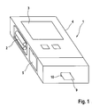
- Fig. 1 shows a compact handheld portable analyzer 1 for examining a sample, particularly a biological fluid, for a medically important ingredient such as blood, urine or saliva.
- This in Fig. 1 shown handheld analyzer 1 is used to determine the blood glucose content and has a power source 2 in the form of commercially available batteries or solar cells.
- the result of a study is displayed with a display device 3, preferably a liquid crystal display.
- the analysis handset 1 has a housing 4, which has a loading opening 5 for receiving a replaceable drum magazine 6 in a magazine compartment 7.
- the drum magazine 6 by means of an electric motor 8 is gradually rotatable about its geometric longitudinal axis, so that stored in the drum magazine 6 analytical consumable 9 can be removed through a housing opening 10 of the housing 4.
- the substantially cylindrically shaped drum magazine 6 has a plurality of annular chambers 11 arranged around its geometrical longitudinal axis, which can contain analytical consumables 9.
- the number of chambers 11 can be chosen largely arbitrary. As a rule, 10 to 100 chambers 11 are expedient, preferably 15 to 30 chambers 11 are present.
- Each of the chambers 11 has on a front side of the drum magazine 6 a removal opening 12 for removing a consumable 9 and a discharge opening 12 opposite insertion opening 13 for insertion of a plunger 14 of a removal device 29.
- the insertion openings 12 and the removal openings 13 are closed to protect the consumables 9 from harmful environmental influences with a sealing film.
- the consumables 9 are preferably designed as test strips, to which a sample can be applied.
- a reagent contained in the test strip reacts with a medically significant component of the sample, so that the result of the reaction can be evaluated with an analysis sensor 15 of the analysis hand-held device 1.
- an analysis sensor 15 may be, for example, an optical sensor which detects a color change of a consumable 9 formed as a test strip, or be an electrical sensor which detects a change in conductivity of the sample.
- the drum magazine 6 can be rotated stepwise, so that successively each of the Removal openings 12 positioned in alignment with the housing opening 10 of the housing 4 and then by means of the plunger 14 of the removal device 29 a consumable 9 can be pushed out of the chamber 11 positioned for removal.
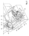
- a special feature of the embodiment shown is that the removal device 29 in addition to the plunger 14 a in Fig. 2 shown drivable feed roller 16 comprises.
- the conveying roller 16 can grip a consumable 9 projecting out of the drum magazine 6 and move it completely or partially out of the drum magazine in the withdrawal direction.
- the conveyor roller 16 therefore makes it possible to carry out the plunger 14 substantially shorter than in devices known in the prior art, since it is sufficient if the consumable 9 can be pushed out of the chamber 11 by the plunger 14 a small distance.
- the conveyor roller 16 is preferably arranged directly adjacent to the removal opening 12 of the inserted drum magazine 6. Between the front side of the inserted drum magazine 6 and the conveyor roller 16 only a small minimum distance of about 1 mm is required so that the conveyor roller 16 and the inserted drum magazine 6 can rotate undisturbed.
- the conveying roller 16 preferably has a small diameter of about 3 to 10 mm, particularly preferably 4 to 7 mm.
- the feed roller 16, together with a stationary relative to their conveying surface a conveying gap, through the consumable 9 is moved in the conveying direction.
- the conveyor roller 16 - as in FIGS. 3 to 7 is shown - also form a conveying gap together with a oppositely arranged counter-roller 31.
- the conveying gap preferably has a profile adapted to the consumable 9, for example in the form of a (running in the conveying direction) groove in the conveying surface or the counter-roll, so that a test field of the consumable 9 is not squeezed during removal and thereby impaired.
- the conveying roller 16 in which the conveying roller 16 cooperates with a stationary conveying surface, has the advantage that the removal device 29 requires less moving parts and therefore can be carried out particularly cost-effective and less susceptible to interference.
- the analysis hand-held device 1 has, in order to support a consumable 9 removed, a conveyor web 17 extending in the removal direction.
- the conveyor surface 33 forming the conveying gap 33 together with the conveying roller 16 is part of the conveyor web 17 so that it extends from the magazine compartment 7 to the housing opening 10. In this way, a removed consumable 9 is supported and guided by the conveyor web 17 on its entire conveying path.
- a further conveying roller 18, which forms a second conveying gap together with the conveying web 17, is arranged at a distance from the conveying roller 16 in the conveying direction. While the first conveyor roller 16 is arranged as close as possible to the removal opening 12 of an inserted drum magazine 6 so that a consumable 9 must protrude as little as possible from its chamber 11 in order to be gripped, the second conveyor roller 18 is as close as possible to the housing opening 10th the housing 4 is arranged, so that a consumable 9 can be pushed out as far as possible from the housing opening 10 of the housing 4.
- a consumable 9 designed as a test strip can be pushed out of the housing opening 10 of the housing 4, the easier it is to apply a sample, for example a drop of blood, to the consumable 9 without the housing 4 being contaminated by the sample ,
- the conveyor web 17 is provided with a groove 19 extending in the conveying direction, which advantageously minimizes friction occurring between the consumable 9 and the conveyor web 17.
- the conveyor web 17 is made of the smoothest possible material with a low coefficient of friction, such as polycarbonate
- the conveyor rollers 16, 18 preferably have a friction-increasing surface with the largest possible friction coefficient.
- the rollers may have a roughened surface, made of hard or soft rubber, or coated with a rubber-like plastic. If the consumables 9 have a thickness that varies over their length, the conveying roller may be spring-loaded in order to take account of thickness differences.
- the conveyor rollers 16, 18 and the plunger 14 of the removal device 29 are moved by a single drive 30.
- the tappet 14 and the conveyor rollers 16, 18 or even for each of the conveyor rollers 16, 18 to provide its own micromotor drive. But it is cheaper and therefore preferred when the removal device 29 has only one drive 30, with both the conveyor rollers 16, 18 and the plunger 14 are driven.
- the removal device 29 has a threaded rod 20 with a thread 21 which extends laterally next to the inserted drum magazine 6 and protrudes on both sides beyond its front side.
- the removal device 29 has a gearbox 22, via which an electric motor belonging to the drive 30 can move the plunger 14.
- the threaded rod 20 has a gear 23 which cooperates with the gear 21, so that the threaded rod 20 via the gear 22 and the gear 23 is set in rotation.
- the gear 23 may be designed as a separate component which is attached to the threaded rod 20, or be integrated into the threaded rod 20 by, for example, a portion of the threaded rod 20 is provided with teeth. In order to make the threaded rod 20 as short as possible, the gear 23 is preferably located at or near one end of the threaded rod 20 and the thread 21 at or near the other end.
- a rotation of the threaded rod 20 can be transferred to the conveying rollers 16, 18 via the external thread 21 arranged at the other end of the threaded rod 20.
- each of the two conveyor rollers 16, 18 is provided with a shaft 24 which carries a gear 25 which engages in the thread 21 of the threaded rod 20.
- the shafts 24 and the threaded rod 20 are mounted by means of bearing rings 26 which are rotatable with low frictional resistance in matching recesses 27 of a carrier 28.
- the conveyor rollers 16, 18 can be driven about their geometric longitudinal axes both clockwise and counterclockwise in order to move a consumable 9 both in the withdrawal direction and in the opposite direction.
- This measure makes it possible to push a consumable 9, for example a test strip, as far as possible out of the housing opening 10 of the housing 4, in order to facilitate the application of a sample and then to draw the consumable 9 back into the analyzer handset 1.
- This makes it possible to arrange the analysis sensor 15 at a protected location in the interior of the housing 4, where disturbing environmental influences, such as scattered light, are minimized.
- the analysis sensor 15 between the two conveyor rollers 16, 18, in particular on the conveyor rollers 16, 18 opposite side of the conveyor web 17 is arranged.
- the conveyor web 17 is provided between the two conveyor rollers 16, 18 with a recess so that the analysis sensor 15 can detect a sample applied to a consumable 9.
- the extending in the conveying direction groove 19 of the conveyor web 17 is dimensioned in its width and depth so that an applied to the consumable 9 sample does not come into contact with the conveyor web 17.
- the plunger 14 is equipped with a gripping element, which with a consumable 9 can come into operative engagement and makes it possible to exert on the plunger 14 and tensile forces on a consumable 9 can.
- the gripping element can be designed as an electromagnet which attracts an iron part of the consumable or as a mechanical hook, which, at a given tensile force, as it is exerted by the conveyor roller 16, folds over and releases the consumable 9.
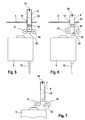
- FIGS. 3 to 7 show in a schematic representation of another embodiment of a removal device when removing a consumable 9 from a drum magazine 6.
- removal device 29 of the conveying gap 33 is not formed by the conveying roller 16 and a stationary relative to their conveying surface, but by the conveying roller 16 and a counter-roller 31 arranged opposite her.
- both the conveying roller 16 and the counter-roller 31 may each be formed drivable.
- the counter-roller 31 it is sufficient if it is rotatably mounted, so that it can be set in rotation by a passing through the conveying gap 33 consumable 9.
- the consumables 9 are designed as test strips which have a test field 32 for receiving a sample.
- the test field 32 is not affected when removing the consumable 9 from the drum magazine 6 and a sample on it can not pollute the removal device 29, in particular not the feed roller 16 and the counter-roller 31, occurs in the illustrated embodiment, the consumable 9 through the Conveying gap, that the test field 32 of the consumable 9 extends transversely to the geometric axis of rotation of the conveying roller 16.
- the risk of deterioration of the test field 32 of the consumable 9 is reduced even further than that in the basis of FIG. 2 described embodiment by a conveying gap 33 with a matched to the consumable 9 profile, for example in the form of a groove 19 in which the conveying surface forming conveyor web 17 can reach.
- FIG. 3 shows the drum magazine 6 with a consumable contained therein 9 together with the removal device 29 in the starting position.
- the consumable 9 is pushed out with the plunger 14 from the drum magazine 6 and gripped by the feed roller 16 as soon as it projects into the conveying gap 33 between the feed roller 16 and the counter roller 31.
- FIG. 5 shows how the consumable 9 is pushed out of the conveyor roller 16 from the housing opening 10 of the analysis handset 1, so that a sample, such as a drop of blood, can be applied to a sample application surface 34, from which it reaches the test field 32. Subsequently, as in FIG.
- FIGS. 8 to 14 show a further embodiment of a hand-held analyzer 1 during insertion of a consumable 9.
- This handheld analyzer 1 differs from the handheld analyzer 1 described above essentially by the fact that it has no loading port for receiving a removable drum magazine.
- analytical consumables 9 in the form of test strips are supplied to the device externally through the housing opening 10.
- a micro-switch (not shown) is actuated, by which a drive of the feed roller 16 and the counter-roller 31 is turned on.
- the consumable 9 is then gripped by the conveying roller 16 and the counter-roller 31 and drawn along the conveying path in the device interior.
- a consumable 9 is therefore from the in Fig. 10 shown input position first in the in Fig. 11 shown test position, in which it is checked if it is not spoiled. This is done by means of an optical measuring device with which a film white value of the consumable 9 is determined.
- a consumable 9 designed as a test strip has for this purpose, for example in the area of the test field 32, a section with a white plastic film which discolors with increasing aging and moisture absorption.
- the film white value By determining the film white value, it can be determined whether the inserted consumable 9 is spoiled. Is a consumable 9 spoiled, it is ejected by means of the feed roller 16 and the counter-roller 31 from the analysis handset 1. Is the consumable 9 still functional, it is by means of the feed roller 16 and the counter-roller 31 along the conveying path in the in Fig. 14 brought shown sample loading position. In the sample application position, the consumable 9 protrudes with one end out of the housing opening 10, so that a sample, for example a drop of blood, can be applied to the sample application surface 34.
- the consumable 9 in the in Fig. 14 shown sample application position may protrude so far from the housing opening 10 that a sample can be easily applied to the sample application surface 34 without the handheld analyzer 1 soiling it.
- the test field 32, to which the sample is supplied, for example, by capillary forces will order so close to the sample application area 34 that the required sample volume is minimal.
Landscapes
- Health & Medical Sciences (AREA)
- Engineering & Computer Science (AREA)
- Biomedical Technology (AREA)
- Life Sciences & Earth Sciences (AREA)
- Physics & Mathematics (AREA)
- Chemical & Material Sciences (AREA)
- Medicinal Chemistry (AREA)
- General Health & Medical Sciences (AREA)
- Molecular Biology (AREA)
- Urology & Nephrology (AREA)
- Biophysics (AREA)
- Food Science & Technology (AREA)
- Optics & Photonics (AREA)
- Analytical Chemistry (AREA)
- Biochemistry (AREA)
- Hematology (AREA)
- General Physics & Mathematics (AREA)
- Immunology (AREA)
- Pathology (AREA)
- Automatic Analysis And Handling Materials Therefor (AREA)
- Investigating Or Analysing Biological Materials (AREA)
- Sampling And Sample Adjustment (AREA)
- Investigating Or Analysing Materials By Optical Means (AREA)
- Investigating Or Analysing Materials By The Use Of Chemical Reactions (AREA)
Applications Claiming Priority (2)
| Application Number | Priority Date | Filing Date | Title |
|---|---|---|---|
| DE102004010529A DE102004010529B4 (de) | 2004-03-04 | 2004-03-04 | Analysehandgerät |
| EP05707236A EP1745284B1 (de) | 2004-03-04 | 2005-02-05 | Analysehandgerät mit förderweg für analytische verbrauchsmittel |
Related Parent Applications (1)
| Application Number | Title | Priority Date | Filing Date |
|---|---|---|---|
| EP05707236A Division EP1745284B1 (de) | 2004-03-04 | 2005-02-05 | Analysehandgerät mit förderweg für analytische verbrauchsmittel |
Publications (1)
| Publication Number | Publication Date |
|---|---|
| EP1936374A1 true EP1936374A1 (de) | 2008-06-25 |
Family
ID=34877349
Family Applications (2)
| Application Number | Title | Priority Date | Filing Date |
|---|---|---|---|
| EP08005435A Withdrawn EP1936374A1 (de) | 2004-03-04 | 2005-02-05 | Analysehandgerät mit Förderweg für analytische Verbrauchsmittel |
| EP05707236A Expired - Lifetime EP1745284B1 (de) | 2004-03-04 | 2005-02-05 | Analysehandgerät mit förderweg für analytische verbrauchsmittel |
Family Applications After (1)
| Application Number | Title | Priority Date | Filing Date |
|---|---|---|---|
| EP05707236A Expired - Lifetime EP1745284B1 (de) | 2004-03-04 | 2005-02-05 | Analysehandgerät mit förderweg für analytische verbrauchsmittel |
Country Status (8)
Cited By (2)
| Publication number | Priority date | Publication date | Assignee | Title |
|---|---|---|---|---|
| EP2177155A1 (de) * | 2008-10-20 | 2010-04-21 | F. Hoffmann-Roche AG | Analytisches Testbandinstrument mit Gleichstrommotor und Getriebe |
| WO2010060598A1 (en) * | 2008-11-26 | 2010-06-03 | Roche Diagnostics Gmbh | Drum type container for analytical elements |
Families Citing this family (11)
| Publication number | Priority date | Publication date | Assignee | Title |
|---|---|---|---|---|
| CN101022762A (zh) | 2004-09-20 | 2007-08-22 | 拜尔保健有限公司 | 用于接种以后改变诊断测试条位置的系统和方法 |
| TW200706864A (en) * | 2005-06-03 | 2007-02-16 | Bayer Healthcare Llc | Solar-powered integrated-diagnostic instrument |
| EP2071326B1 (en) * | 2006-08-03 | 2016-11-09 | Panasonic Healthcare Holdings Co., Ltd. | Measuring device and sensor ejecting method |
| DE502007001040D1 (de) * | 2007-05-19 | 2009-08-20 | Roche Diagnostics Gmbh | Analysehandgerät zum Untersuchen einer Probe |
| US8394637B2 (en) | 2008-06-02 | 2013-03-12 | Roche Diagnostics Operations, Inc. | Handheld analyzer for testing a sample |
| US8574510B2 (en) | 2009-09-30 | 2013-11-05 | Bayer Healthcare Llc | Stackable electrochemical analyte sensors, systems and methods including same |
| DK2802259T3 (en) * | 2012-01-10 | 2016-01-25 | Sanofi Aventis Deutschland | Effort to test element |
| TWI564562B (zh) * | 2013-03-11 | 2017-01-01 | 亞宣西亞糖尿病治療控股股份有限公司 | 條帶抓取器 |
| US9376708B2 (en) | 2013-03-13 | 2016-06-28 | Ascensia Diabetes Care Holdings Ag | Bottled glucose sensor with no handling |
| CN105813809B (zh) | 2013-11-27 | 2017-08-29 | 豪夫迈·罗氏有限公司 | 手柄测试带射出器 |
| US20150176053A1 (en) * | 2013-12-23 | 2015-06-25 | Cilag Gmbh International | Test strip insertion drive mechanism for analyte meter |
Citations (5)
| Publication number | Priority date | Publication date | Assignee | Title |
|---|---|---|---|---|
| US3918910A (en) * | 1973-07-31 | 1975-11-11 | Olympus Optical Co | System for detecting the particular chemical constituent of a fluid |
| EP0640393A1 (de) * | 1993-08-27 | 1995-03-01 | Roche Diagnostics GmbH | System zur Bevorratung von Testelementen |
| EP1022565A2 (de) | 1999-01-23 | 2000-07-26 | Roche Diagnostics GmbH | Verfahren und Vorrichtung zum Entnehmen analytischer Verbrauchsmittel aus einem Vorratsbehältnis |
| US20020057993A1 (en) | 2000-08-30 | 2002-05-16 | Hypoguard Limited | Test device |
| DE10156811A1 (de) * | 2001-11-20 | 2003-06-05 | Quidel Corp | Teststreifenanalysegerät |
Family Cites Families (23)
| Publication number | Priority date | Publication date | Assignee | Title |
|---|---|---|---|---|
| DE2407320A1 (de) * | 1974-02-15 | 1975-08-28 | Benzing Kontrolluhren | Geraet zur arbeits- und auftragszeiterfassung |
| US4065263A (en) * | 1976-04-02 | 1977-12-27 | Woodbridge Iii Richard G | Analytical test strip apparatus |
| AU540481B2 (en) * | 1980-02-14 | 1984-11-22 | Hermann Stockburger | Authorization card |
| US4302420A (en) * | 1981-01-09 | 1981-11-24 | Eastman Kodak Company | Analyzer featuring a contacting reflectometer |
| US4876204A (en) * | 1984-10-11 | 1989-10-24 | Kabushiki Kaisha Kyoto Daiichi Kagaku | Method and apparatus of automatic continuous analysis using analytical implement |
| US4791461A (en) * | 1984-11-27 | 1988-12-13 | Syntex (U.S.A.) Inc. | Portable analyzer |
| US4710352A (en) * | 1985-09-20 | 1987-12-01 | Eastman Kodak Company | Simplified test element advancing mechanism having positive engagement with element |
| US5236078A (en) * | 1986-07-30 | 1993-08-17 | Hoechst Aktiengesellschaft | Apparatus for fixing the position of the test zones of a test strip and for reversing the latter |
| US4857471A (en) * | 1987-07-20 | 1989-08-15 | Eastman Kodak Company | Analyzer with wash station separate from incubator |
| US4833088A (en) * | 1987-09-25 | 1989-05-23 | Miles Inc. | Reagent strip handling mechanism |
| DE3807565A1 (de) * | 1988-03-08 | 1989-09-21 | Boehringer Mannheim Gmbh | Vorrichtung zur ueberfuehrung von teststreifen zu einer untersuchungseinrichtung |
| US5073342A (en) * | 1989-01-05 | 1991-12-17 | Eastman Kodak Company | Reciprocating transfer mechanism |
| JP2812625B2 (ja) * | 1992-10-19 | 1998-10-22 | 株式会社日立製作所 | 液体試料自動分析装置 |
| DE4425439A1 (de) * | 1994-07-19 | 1996-01-25 | Boehringer Mannheim Gmbh | Teststreifenauswertegerät mit einer Transporteinheit für Teststreifen |
| US5575403A (en) * | 1995-01-13 | 1996-11-19 | Bayer Corporation | Dispensing instrument for fluid monitoring sensors |
| US5510266A (en) * | 1995-05-05 | 1996-04-23 | Bayer Corporation | Method and apparatus of handling multiple sensors in a glucose monitoring instrument system |
| JP3187845B2 (ja) | 1996-05-30 | 2001-07-16 | ラジオメーター・メディカル・アクティーゼルスカブ | 少なくとも一つの生理的液体試料における少なくとも一つのパラメータを測定するための方法及びシステム、ホルダ、並びに、試験装置 |
| DE19715031A1 (de) * | 1997-04-11 | 1998-10-15 | Boehringer Mannheim Gmbh | Magazin zur Bevorratung von Testelementen |
| SG102538A1 (en) * | 1998-04-24 | 2004-03-26 | Roche Diagnostics Gmbh | Storage container for analytical devices |
| DE19819407A1 (de) * | 1998-04-30 | 1999-11-11 | Hendrik Priebs | Teststreifenbehälter für Messgeräte, die mit Einwegteststreifen arbeiten |
| JP4216434B2 (ja) * | 2000-02-02 | 2009-01-28 | 大塚製薬株式会社 | 試験紙測定装置 |
| GB0021219D0 (en) * | 2000-08-30 | 2000-10-18 | Hypoguard Ltd | Test device |
| US20030212344A1 (en) * | 2002-05-09 | 2003-11-13 | Vadim Yuzhakov | Physiological sample collection devices and methods of using the same |
-
2004
- 2004-03-04 DE DE102004010529A patent/DE102004010529B4/de not_active Expired - Fee Related
-
2005
- 2005-02-05 JP JP2007501140A patent/JP4653801B2/ja not_active Expired - Fee Related
- 2005-02-05 CA CA2557996A patent/CA2557996C/en not_active Expired - Fee Related
- 2005-02-05 ES ES05707236T patent/ES2306093T3/es not_active Expired - Lifetime
- 2005-02-05 WO PCT/EP2005/001196 patent/WO2005085840A1/de active IP Right Grant
- 2005-02-05 AT AT05707236T patent/ATE394669T1/de active
- 2005-02-05 EP EP08005435A patent/EP1936374A1/de not_active Withdrawn
- 2005-02-05 DE DE502005004009T patent/DE502005004009D1/de not_active Expired - Lifetime
- 2005-02-05 EP EP05707236A patent/EP1745284B1/de not_active Expired - Lifetime
- 2005-02-05 US US10/591,311 patent/US7922974B2/en not_active Expired - Fee Related
Patent Citations (5)
| Publication number | Priority date | Publication date | Assignee | Title |
|---|---|---|---|---|
| US3918910A (en) * | 1973-07-31 | 1975-11-11 | Olympus Optical Co | System for detecting the particular chemical constituent of a fluid |
| EP0640393A1 (de) * | 1993-08-27 | 1995-03-01 | Roche Diagnostics GmbH | System zur Bevorratung von Testelementen |
| EP1022565A2 (de) | 1999-01-23 | 2000-07-26 | Roche Diagnostics GmbH | Verfahren und Vorrichtung zum Entnehmen analytischer Verbrauchsmittel aus einem Vorratsbehältnis |
| US20020057993A1 (en) | 2000-08-30 | 2002-05-16 | Hypoguard Limited | Test device |
| DE10156811A1 (de) * | 2001-11-20 | 2003-06-05 | Quidel Corp | Teststreifenanalysegerät |
Cited By (6)
| Publication number | Priority date | Publication date | Assignee | Title |
|---|---|---|---|---|
| EP2177155A1 (de) * | 2008-10-20 | 2010-04-21 | F. Hoffmann-Roche AG | Analytisches Testbandinstrument mit Gleichstrommotor und Getriebe |
| WO2010046323A1 (de) * | 2008-10-20 | 2010-04-29 | F. Hoffmann-La Roche Ag | Analytisches testbandinstrument mit gleichstromotor und getriebe |
| US8383040B2 (en) | 2008-10-20 | 2013-02-26 | Roche Diagnostics Operations, Inc. | Analytical test tape instrument |
| WO2010060598A1 (en) * | 2008-11-26 | 2010-06-03 | Roche Diagnostics Gmbh | Drum type container for analytical elements |
| US8147755B2 (en) | 2008-11-26 | 2012-04-03 | Roche Diagnostics Operations, Inc. | Drum type container for analytical elements |
| US8372352B2 (en) | 2008-11-26 | 2013-02-12 | Roche Diagnostics Operations, Inc. | Biosensor assembly with drum type container for analytical elements |
Also Published As
| Publication number | Publication date |
|---|---|
| DE102004010529A1 (de) | 2005-09-22 |
| EP1745284A1 (de) | 2007-01-24 |
| US7922974B2 (en) | 2011-04-12 |
| DE102004010529B4 (de) | 2007-09-06 |
| ATE394669T1 (de) | 2008-05-15 |
| CA2557996C (en) | 2011-04-12 |
| CA2557996A1 (en) | 2005-09-15 |
| US20070183925A1 (en) | 2007-08-09 |
| JP2007526464A (ja) | 2007-09-13 |
| ES2306093T3 (es) | 2008-11-01 |
| WO2005085840A1 (de) | 2005-09-15 |
| JP4653801B2 (ja) | 2011-03-16 |
| DE502005004009D1 (de) | 2008-06-19 |
| EP1745284B1 (de) | 2008-05-07 |
Similar Documents
| Publication | Publication Date | Title |
|---|---|---|
| EP1574855B1 (de) | Analysehandgerät | |
| EP1022565B1 (de) | Verfahren und Vorrichtung zum Entnehmen analytischer Verbrauchsmittel aus einem Vorratsbehältnis | |
| EP1745284B1 (de) | Analysehandgerät mit förderweg für analytische verbrauchsmittel | |
| DE10361261B4 (de) | Analysehandgerät | |
| EP1997429B1 (de) | Flexible Lanzette in einem Lanzettensystem | |
| EP2130493B1 (de) | Analysesystem zur Bestimmung eines Analyten in einer Körperflüssigkeit, Magazin für ein Analysegerät und Verfahren zur Herstellung eines Magazins für ein Analysegerät. | |
| EP0319922B1 (de) | Vorrichtung zur optischen Auswertung eines mindestens ein Testfeld aufweisenden Teststreifens | |
| EP1975610B1 (de) | Analysegerät mit austauschbarem Testelementmagazin | |
| DE60310160T2 (de) | Streifen zur Verpackung einer Mehrzahl von Geräten zur Flüssigkeitsentnahme und Testung sowie Verfahren zur Herstellung und Verwendung des Streifens | |
| EP2129289B1 (de) | Analysesystem zur bestimmung eines analyten in einer körperflüssigkeit und disposibles integriertes probengewinnungs- und analyseelement | |
| WO2006136527A2 (de) | Testvorrichtung mit testelement-lagervorrichtung | |
| EP2101646B1 (de) | Stechgerät | |
| EP2039294A1 (de) | Stechsystem und Bandkassette | |
| EP0871033A2 (de) | Teststreifenpackung und Messgerät zur Verwendung einer solchen | |
| WO2009030340A1 (de) | Analysegerät zur bestimmung eines analyten in einer körperflüssigkeit, magazin für ein analysegerät und verfahren zur erzeugung einer wunde zum untersuchen einer austretenden körperflüssigkeit | |
| EP1995594B1 (de) | Analysehandgerät zum Untersuchen einer Probe | |
| EP2194872B1 (de) | Stechsystem | |
| EP2135546B1 (de) | Bandkassette für ein medizinisches Handgerät | |
| EP2442708B1 (de) | Stechsystem | |
| EP1621885A2 (de) | Analysesystem mit Testelementhalter | |
| EP1672364A1 (de) | Analysesystem zur Analyse einer flüssigen Probe auf einem analytischen Testelement | |
| DE19635012C2 (de) | Vorrichtung und Verfahren zur Volumenbestimmung von Flüssigkeiten |
Legal Events
| Date | Code | Title | Description |
|---|---|---|---|
| PUAI | Public reference made under article 153(3) epc to a published international application that has entered the european phase |
Free format text: ORIGINAL CODE: 0009012 |
|
| AC | Divisional application: reference to earlier application |
Ref document number: 1745284 Country of ref document: EP Kind code of ref document: P |
|
| AK | Designated contracting states |
Kind code of ref document: A1 Designated state(s): AT BE BG CH CY CZ DE DK EE ES FI FR GB GR HU IE IS IT LI LT LU MC NL PL PT RO SE SI SK TR |
|
| RTI1 | Title (correction) |
Free format text: HANDHELD ANALYSIS DEVICE WITH CONVEYOR PATH FOR ANALYTICAL CONSUMABLES |
|
| 17P | Request for examination filed |
Effective date: 20081008 |
|
| AKX | Designation fees paid |
Designated state(s): AT BE BG CH CY CZ DE DK EE ES FI FR GB GR HU IE IS IT LI LT LU MC NL PL PT RO SE SI SK TR |
|
| GRAP | Despatch of communication of intention to grant a patent |
Free format text: ORIGINAL CODE: EPIDOSNIGR1 |
|
| STAA | Information on the status of an ep patent application or granted ep patent |
Free format text: STATUS: THE APPLICATION IS DEEMED TO BE WITHDRAWN |
|
| 18D | Application deemed to be withdrawn |
Effective date: 20130124 |