EP1936186A2 - Windenergieanlage und Verfahren zur Detektion asymmetrischer Vereisung einer Windenergieanlage - Google Patents
Windenergieanlage und Verfahren zur Detektion asymmetrischer Vereisung einer Windenergieanlage Download PDFInfo
- Publication number
- EP1936186A2 EP1936186A2 EP20070123024 EP07123024A EP1936186A2 EP 1936186 A2 EP1936186 A2 EP 1936186A2 EP 20070123024 EP20070123024 EP 20070123024 EP 07123024 A EP07123024 A EP 07123024A EP 1936186 A2 EP1936186 A2 EP 1936186A2
- Authority
- EP
- European Patent Office
- Prior art keywords
- acceleration
- rotor
- rotorspeed
- determining whether
- icing
- Prior art date
- Legal status (The legal status is an assumption and is not a legal conclusion. Google has not performed a legal analysis and makes no representation as to the accuracy of the status listed.)
- Granted
Links
- 238000000034 method Methods 0.000 title claims abstract description 73
- 230000001133 acceleration Effects 0.000 claims abstract description 97
- 238000012544 monitoring process Methods 0.000 claims abstract description 11
- 238000004891 communication Methods 0.000 description 20
- 238000010586 diagram Methods 0.000 description 12
- 238000004590 computer program Methods 0.000 description 10
- 230000006870 function Effects 0.000 description 8
- 238000001514 detection method Methods 0.000 description 6
- 238000012545 processing Methods 0.000 description 6
- 230000003287 optical effect Effects 0.000 description 4
- 230000005236 sound signal Effects 0.000 description 3
- 238000009825 accumulation Methods 0.000 description 2
- 230000008878 coupling Effects 0.000 description 2
- 238000010168 coupling process Methods 0.000 description 2
- 238000005859 coupling reaction Methods 0.000 description 2
- 230000008569 process Effects 0.000 description 2
- 230000009471 action Effects 0.000 description 1
- 230000008901 benefit Effects 0.000 description 1
- 230000005540 biological transmission Effects 0.000 description 1
- 230000001413 cellular effect Effects 0.000 description 1
- 230000000694 effects Effects 0.000 description 1
- 230000008014 freezing Effects 0.000 description 1
- 238000007710 freezing Methods 0.000 description 1
- 238000009434 installation Methods 0.000 description 1
- 238000004519 manufacturing process Methods 0.000 description 1
- 239000013307 optical fiber Substances 0.000 description 1
- 238000010248 power generation Methods 0.000 description 1
- 230000009467 reduction Effects 0.000 description 1
- 239000004065 semiconductor Substances 0.000 description 1
- 238000012546 transfer Methods 0.000 description 1
Images


Classifications
-
- F—MECHANICAL ENGINEERING; LIGHTING; HEATING; WEAPONS; BLASTING
- F03—MACHINES OR ENGINES FOR LIQUIDS; WIND, SPRING, OR WEIGHT MOTORS; PRODUCING MECHANICAL POWER OR A REACTIVE PROPULSIVE THRUST, NOT OTHERWISE PROVIDED FOR
- F03D—WIND MOTORS
- F03D80/00—Details, components or accessories not provided for in groups F03D1/00 - F03D17/00
- F03D80/40—Ice detection; De-icing means
-
- F—MECHANICAL ENGINEERING; LIGHTING; HEATING; WEAPONS; BLASTING
- F05—INDEXING SCHEMES RELATING TO ENGINES OR PUMPS IN VARIOUS SUBCLASSES OF CLASSES F01-F04
- F05B—INDEXING SCHEME RELATING TO WIND, SPRING, WEIGHT, INERTIA OR LIKE MOTORS, TO MACHINES OR ENGINES FOR LIQUIDS COVERED BY SUBCLASSES F03B, F03D AND F03G
- F05B2260/00—Function
- F05B2260/80—Diagnostics
-
- F—MECHANICAL ENGINEERING; LIGHTING; HEATING; WEAPONS; BLASTING
- F05—INDEXING SCHEMES RELATING TO ENGINES OR PUMPS IN VARIOUS SUBCLASSES OF CLASSES F01-F04
- F05B—INDEXING SCHEME RELATING TO WIND, SPRING, WEIGHT, INERTIA OR LIKE MOTORS, TO MACHINES OR ENGINES FOR LIQUIDS COVERED BY SUBCLASSES F03B, F03D AND F03G
- F05B2270/00—Control
- F05B2270/30—Control parameters, e.g. input parameters
- F05B2270/309—Rate of change of parameters
-
- F—MECHANICAL ENGINEERING; LIGHTING; HEATING; WEAPONS; BLASTING
- F05—INDEXING SCHEMES RELATING TO ENGINES OR PUMPS IN VARIOUS SUBCLASSES OF CLASSES F01-F04
- F05B—INDEXING SCHEME RELATING TO WIND, SPRING, WEIGHT, INERTIA OR LIKE MOTORS, TO MACHINES OR ENGINES FOR LIQUIDS COVERED BY SUBCLASSES F03B, F03D AND F03G
- F05B2270/00—Control
- F05B2270/30—Control parameters, e.g. input parameters
- F05B2270/327—Rotor or generator speeds
-
- F—MECHANICAL ENGINEERING; LIGHTING; HEATING; WEAPONS; BLASTING
- F05—INDEXING SCHEMES RELATING TO ENGINES OR PUMPS IN VARIOUS SUBCLASSES OF CLASSES F01-F04
- F05B—INDEXING SCHEME RELATING TO WIND, SPRING, WEIGHT, INERTIA OR LIKE MOTORS, TO MACHINES OR ENGINES FOR LIQUIDS COVERED BY SUBCLASSES F03B, F03D AND F03G
- F05B2270/00—Control
- F05B2270/30—Control parameters, e.g. input parameters
- F05B2270/334—Vibration measurements
-
- F—MECHANICAL ENGINEERING; LIGHTING; HEATING; WEAPONS; BLASTING
- F05—INDEXING SCHEMES RELATING TO ENGINES OR PUMPS IN VARIOUS SUBCLASSES OF CLASSES F01-F04
- F05B—INDEXING SCHEME RELATING TO WIND, SPRING, WEIGHT, INERTIA OR LIKE MOTORS, TO MACHINES OR ENGINES FOR LIQUIDS COVERED BY SUBCLASSES F03B, F03D AND F03G
- F05B2270/00—Control
- F05B2270/80—Devices generating input signals, e.g. transducers, sensors, cameras or strain gauges
- F05B2270/807—Accelerometers
-
- Y—GENERAL TAGGING OF NEW TECHNOLOGICAL DEVELOPMENTS; GENERAL TAGGING OF CROSS-SECTIONAL TECHNOLOGIES SPANNING OVER SEVERAL SECTIONS OF THE IPC; TECHNICAL SUBJECTS COVERED BY FORMER USPC CROSS-REFERENCE ART COLLECTIONS [XRACs] AND DIGESTS
- Y02—TECHNOLOGIES OR APPLICATIONS FOR MITIGATION OR ADAPTATION AGAINST CLIMATE CHANGE
- Y02E—REDUCTION OF GREENHOUSE GAS [GHG] EMISSIONS, RELATED TO ENERGY GENERATION, TRANSMISSION OR DISTRIBUTION
- Y02E10/00—Energy generation through renewable energy sources
- Y02E10/70—Wind energy
- Y02E10/72—Wind turbines with rotation axis in wind direction
Definitions
- the present invention relates to ice accumulation occurring on the rotor blades of a wind turbine; and more particularly a method and system for detecting asymmetric icing.
- Wind turbines are commonly installed in areas where the climatic conditions allow for ice accumulation (hereinafter icing). Icing on the rotor blades (hereinafter blades) of a wind turbine typically leads to several problems including a reduction in power output; and higher stresses on several components. Icing may be divided into two forms, symmetric (icing on all blades) and asymmetric, (icing on some blades). Asymmetric icing increases the wind turbine tower vibration and also increases the rotorspeed acceleration. Asymmetric icing may also yield a rotor-mass imbalance leading to higher fatigue loads, and thus requiring more robust and expensive wind turbine components.
- a method of detecting asymmetric icing on a wind turbine includes: providing a rotorspeed acceleration monitoring system; determining from the rotorspeed acceleration monitoring system whether a rotorspeed acceleration is above a rotorspeed acceleration limit; determining whether a rotor-mass imbalance condition exists; and determining whether a longitudinal tower acceleration coincides with icing on a rotor.
- a system for detecting asymmetric icing on a wind turbine includes: a rotorspeed acceleration monitoring system; means for determining whether a rotorspeed acceleration is above an acceleration limit from the rotorspeed acceleration monitoring system; means for determining whether a rotor-mass imbalance condition exists; and means for determining whether the longitudinal tower acceleration coincides with icing on a rotor.
- a wind turbine includes: a tower; a nacelle; a rotorspeed acceleration monitoring system; means for determining whether rotor acceleration data is available; and if rotor acceleration data is available, then further comprising: means for receiving rotorspeed acceleration data; and means for determining whether a rotorspeed acceleration is above a rotorspeed acceleration limit; otherwise if rotor acceleration data is not available, then further comprising: means for receiving tower vibration data; and means for determining whether a longitudinal tower acceleration is above a longitudinal acceleration limit; means for determining whether a rotor-mass imbalance condition exists comprising: means for determining whether a longitudinal tower acceleration frequency is approximately a rotor frequency; and means for receiving a rotorspeed; or means for determining whether a maximum longitudinal tower acceleration repeatedly occurs near the rotor location where the immediately previous maximum longitudinal tower acceleration occurred; and means for receiving a rotor position; means for determining whether the longitudinal tower acceleration coincides with icing on a rotor
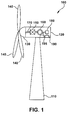
- Figure 1 is a schematic illustrating the environment in which an embodiment of the present invention operates.
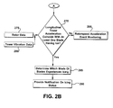
- Figures 2A and 2B are flowcharts illustrating an example of a method of detecting asymmetric icing in accordance with an embodiment of the present invention.
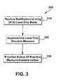
- Figure 3 is a flowchart illustrating an example of a method of responding to a detection of asymmetric icing in accordance with an embodiment of the present invention.
- Figure 4 is a block diagram of an exemplary system for detecting asymmetric icing in accordance with an embodiment of the present invention.
- the present invention may be embodied as a method, system, or computer program product. Accordingly, the present invention may take the form of an entirely hardware embodiment, an entirely software embodiment (including firmware, resident software, micro-code, etc.) or an embodiment combining software and hardware aspects all generally referred to herein as a "circuit", "module,” or " system. " Furthermore, the present invention may take the form of a computer program product on a computer-usable storage medium having computer-usable program code embodied in the medium.
- the computer-usable or computer-readable medium may be, for example but not limited to, an electronic, magnetic, optical, electromagnetic, infrared, or semiconductor system, apparatus, device, or propagation medium. More specific examples (a non exhaustive list) of the computer-readable medium would include the following: an electrical connection having one or more wires, a portable computer diskette, a hard disk, a random access memory (RAM), a read-only memory (ROM), an erasable programmable read-only memory (EPROM or Flash memory), an optical fiber, a portable compact disc read-only memory (CD-ROM), an optical storage device, a transmission media such as those supporting the Internet or an intranet, or a magnetic storage device.
- the computer-usable or computer-readable medium could even be paper or another suitable medium upon which the program is printed, as the program can be electronically captured, via, for instance, optical scanning of the paper or other medium, then compiled, interpreted, or otherwise processed in a suitable manner, if necessary, and then stored in a computer memory.
- a computer-usable or computer-readable medium may be any medium that can contain, store, communicate, propagate, or transport the program for use by or in connection with the instruction execution system, apparatus, or device.
- Computer program code for carrying out operations of the present invention may be written in an object oriented programming language such as Java7, Smalltalk or C++, or the like. However, the computer program code for carrying out operations of the present invention may also be written in conventional procedural programming languages, such as the "C" programming language, or a similar language.
- the program code may execute entirely on the user's computer, partly on the user's computer, as a stand-alone software package, partly on the user's computer and partly on a remote computer or entirely on the remote computer. In the latter scenario, the remote computer may be connected to the user's computer through a local area network (LAN) or a wide area network (WAN), or the connection may be made to an external computer (for example, through the Internet using an Internet Service Provider).
- LAN local area network
- WAN wide area network
- Internet Service Provider for example, AT&T, MCI, Sprint, EarthLink, MSN, GTE, etc.
- These computer program instructions may also be stored in a computer-readable memory that can direct a computer or other programmable data processing apparatus to function in a particular manner, such that the instructions stored in the computer-readable memory produce an article of manufacture including instruction means which implement the function/act specified in the flowchart and/or block diagram block or blocks.
- the computer program instructions may also be loaded onto a computer or other programmable data processing apparatus to cause a series of operational steps to be performed on the computer or other programmable apparatus to produce a computer implemented process such that the instructions which execute on the computer or other programmable apparatus provide steps for implementing the functions/acts specified in the flowchart and/or block diagram block or blocks.
- An embodiment of the present invention takes the form of a software application and process that utilizes rotorspeed acceleration to detect asymmetric icing on a wind turbine.
- the present invention can be applied to many forms of wind turbines (hereinafter turbine) including those located in regions, which may not typically have atmospheric conditions that support icing.
- the present invention may be configured to automatically or continuously monitor rotorspeed acceleration while the turbine operates, to determine whether or not asymmetric icing may be occurring.
- the present invention may be configured to require a user action to initiate operation.
- the present invention may function as a stand-alone system.
- the present invention may be integrated as a module, or the like, within a broader system, such as a turbine control or a plant control system.
- FIG. 1 is a schematic illustrating the environment in which an embodiment of the present invention operates.
- a turbine 100 includes a tower 110 on which a nacelle 120 is mounted. At a lateral end of the nacelle 120, a hub 130 is mounted which supports a plurality of blades 140.
- a gear box 150 and a generator 160 are disposed within the nacelle 120.
- the gear box 150 and the generator 160 are connected to the hub 130 via a drive train 1'70.
- an asymmetric icing detection system 180 (hereinafter system 180) may also be disposed within the nacelle 120.
- Communicating with the system 180 is a vibration sensor 190 and a rotorspeed sensor 195.
- the sensor 190 measures the tower vibration.
- One advantage of the present invention is that the sensors 190, 195 are typically normal components of a turbine 100. Therefore, a user is not required to purchase, install, and maintain and new sensors.
- An embodiment of the system 180 of the present invention may receive rotorspeed data from the rotorspeed sensors 195 to determine whether or not at least one blade 140 may be experiencing icing. In the event that the rotorspeed sensor 195 is not available, the present invention will use the vibration sensor 190 to determine whether or not at least one blade 140 may be experiencing icing.
- FIGS. 2A and 2B are a flowchart illustrating a method 200 of detecting asymmetric icing, in accordance with an embodiment of the present invention.
- the method 200 is enabled to monitoring the activity of a turbine.
- An embodiment of the method 200 may be configured to continuously operate to determine whether or not icing may be occurring on at least one blade.
- step 210 the method 200 determines whether or not rotorspeed acceleration data is available. If the rotorspeed acceleration is available, then the method 200 proceeds to step 215; otherwise the method 200 proceeds to step 225.
- step 215 the method 200 determines whether or not the rotorspeed acceleration is above a rotorspeed acceleration limit.
- Step 215 compares actual rotorspeed acceleration data to a preconfigured rotorspeed acceleration limit.
- the present invention may receive actual rotorspeed data from rotorspeed sensor 195.
- the preconfigured rotorspeed acceleration limit may be a user settable parameter.
- the preconfigured rotorspeed acceleration limit may be received by step 215 from another control system, such as a plant control system, or the like.
- the method 200 at step 215 receives the rotorspeed acceleration data from step 220. If the rotorspeed acceleration does not exceed the limit, then the method 200 reverts to step 205, otherwise the method 200 proceeds to either step 235 or step 245.
- step 225 the method 200 determines whether or not the longitudinal tower acceleration is above a longitudinal acceleration limit.
- Step 225 incorporates actual tower vibration data to calculate a longitudinal tower acceleration, which is then compared to a preconfigured longitudinal acceleration limit.
- the present invention may receive actual tower vibration data from vibration sensor 190.
- the preconfigured acceleration limit may be a user settable parameter.
- the preconfigured acceleration limit may be received by step 225 from another control system, such as a plant control system, or the like.
- step 225 receives the tower vibration data from step 230. If the lateral tower acceleration does not exceed the limit, then the method 200 reverts to step 205, otherwise the method 200 proceeds to either step 235 or step 245.
- the present invention may be utilized on a turbine that has at least one sensor that can provide either rotorspeed data or rotor position data to the method 200. As illustrated, if the present invention is implemented on a turbine having a sensor that provides rotorspeed, then the method 200 proceeds from either step 215 or 225 to step 235; otherwise if the present invention is implemented on a turbine having a sensor that provides rotor position, then the method 200 proceeds from either step 215 or 225 to step 245.
- step 235 the method 200 determines whether or not the frequency of the longitudinal tower acceleration is similar to the rotor frequency.
- Step 235 compares the frequency of longitudinal tower acceleration of block 225 to the actual rotor speed.
- step 235 receives the rotorspeed data from step 240.
- the rotorspeed data may be received from a rotorspeed sensor 195 on the turbine. If the frequency of the longitudinal tower acceleration is similar to the actual rotorspeed, then the method 200 proceeds to step 255; otherwise the method 200 reverts to step 205.
- step 245 the method 200 determines whether or not the maximum longitudinal tower acceleration occurs periodically around the same rotor position.
- Step 230 first determines the value of maximum longitudinal tower acceleration.
- step 245 determines whether or not that value is repeatedly occurring at or near the same rotor position.
- step 245 receives the rotor position data from step 250.
- the rotor position data may be received from a preexisting sensor on the turbine. If the maximum longitudinal tower acceleration is repeatedly occurring at or near the same rotor position, then the method 200 proceeds to step 255; otherwise the method 200 reverts to step 205.
- the method 200 has determined that a rotor-mass imbalance condition is likely.
- the method 200 may be configured to provide a notification that a rotor-mass imbalance condition is likely.
- the notification may be an alarm of varying forms such as, but not limited to, an audio signal, a graphic, or a text message.
- step 260 the method 200 determines whether or not there is a potential for icing on at least one blade.
- Step 260 utilizes ambient weather condition data to determine whether or not icing could occur.
- an embodiment of the present invention may utilize temperature, humidity, and air pressure in determining whether or not icing may occur.
- step 260 receives the ambient weather condition data from step 265. Turbines typically have hardware that provides ambient weather condition data and thus the present invention does not require additional hardware. If step 260 determines that the ambient weather conditions support icing, then the method 200 proceeds to step 270; otherwise the method 200 reverts to step 205.
- step 270 the method 200 determines whether or not the actual longitudinal tower acceleration coincides with longitudinal tower accelerations due to at least one blade having ice.
- step 270 receives rotor data (such as rotor position or rotorspeed) from step 275, and tower vibration data from step 280.
- step 270 utilizes the received data to calculate a range of longitudinal tower accelerations that may result from icing on at least one blade.
- the calculated longitudinal tower accelerations are then compared to either the actual rotorspeed acceleration determined in step 215, or the actual longitudinal tower acceleration determined in step 225, (whichever is available).
- an embodiment of the present invention may compare the actual longitudinal tower acceleration to a previously stored or estimated value.
- step 270 determines that either the actual rotorspeed acceleration or the longitudinal tower acceleration coincide with the calculated longitudinal tower accelerations, then the method 200 proceeds to step 285; otherwise the method 200 reverts to step 205.
- step 270 determines that the actual longitudinal tower acceleration coincides with the estimated or stored longitudinal tower accelerations, then the method 200 proceeds to step 285; otherwise the method 200 reverts to step 205.
- the method 200 determines which blades or blades may be experiencing icing. For example, but not limited to, the method 200 in step 285 may determine if icing occurs on a blade1, or a blade2, or a blade3, or any and all combinations thereof. Furthermore, in step 290, the method 200 may provide notification of which blade or blades may be experiencing icing. Similar to step 255, the notification may be an alarm of varying forms such as, but not limited to, an audio signal, a graphic, or a text message. Furthermore, the method 200 may be configured to transmit the icing status to other control systems, such as the turbine control system, plant control system, or the like.
- FIG. 3 is a flowchart illustrating an example of a method of responding to a detection of asymmetric icing in accordance with an embodiment of the present invention.
- the method 300 receives a notification of icing of at least one blade from the method 200.
- the method 300 may take the form of a control system.
- the control system may include for example, but not limited to, a turbine control system, a plant control system, or the like.
- the notification may be received by the control system, for example, but not limited to, via a wired, wireless, or other forms of electronically transmitting the notification.
- the method 300 may implement at least one reactive measure to reduce or remove the icing.
- a reactive measure may include for example, but not limited to, reducing the rotor speed, lowering a power generation set point, braking procedures, or the like.
- the method 300 provides a status notification on the reactive measure (s) that was implemented.
- the notification may be an alarm of varying forms such as, but not limited to, an audio signal, a graphic, or a text message.
- Figure 4 is a step diagram of an exemplary system 200 to detect asymmetric icing in accordance with an embodiment of the present invention.
- the elements of the method 200 may be embodied in and performed by the system 400.
- the system 400 may include one or more user or client communication devices 402 or similar systems or devices (two are illustrated in Figure 4 ).
- Each communication device 402 may be for example, but not limited to a computer system, a personal digital assistant, a cellular phone, or similar device capable of sending and receiving an electronic message.
- the communication device 402 may include a system memory 404 or local file system.
- the system memory 404 may include for example, but not limited to, a read only memory (ROM) and a random access memory (RAM).
- the ROM may include a basic input/output system (BIOS).
- BIOS may contain basic routines that help to transfer information between elements or components of the communication device 402.
- the system memory 404 may contain an operating system 406 to control overall operation of the communication device 402.
- the system memory 404 may also include a browser 408 or web browser.
- the system memory 404 may also include data structures 410 or computer-executable code to detect asymmetric icing that may be similar or include elements of the method 200 in Figures 2A and 2B .
- the system memory 404 may further include a template cache memory 412, which may be used in conjunction with the method 200 in Figures 2A and 2B to automatically store data from the most recent asymmetric icing detection.
- the communication device 402 may also include a processor or processing unit 414 to control operations of the other components of the communication device 402.
- the operating system 406, browser 408, data structures 410 may be operable on the processor 414.
- the processor 414 may be coupled to the memory system 404 and other components of the communication device 402 by a system bus 416.
- the communication device 402 may also include multiple input devices, output devices or combination input/output devices 418. Each input/output device 418 may be coupled to the system bus 416 by an input/output interface (not shown in Figure 4 ).
- the input and output devices or combination I/O devices 418 permit a user to operate and interface with the communication device 402 and to control operation of the browser 408 and data structures 410 to access, operate and control the software to automatically store data from the most recent asymmetric icing detection.
- the I/O devices 418 may include a keyboard and computer pointing device or the like to perform the operations discussed herein.
- the I/O devices 418 may also include disk drives, optical, mechanical, magnetic, or infrared input/output devices, modems or the like.
- the I/O devices 418 may be used to access a medium 420.
- the medium 420 may contain, store, communicate or transport computer-readable or computer-executable instructions or other information for use by or in connection with a system, such as the communication devices 402.
- the communication device 402 may also include or be connected to other devices, such as a display or monitor 422.
- the monitor 422 may be used to permit the user to interface with the communication device 402.
- the communication device 402 may also include a hard disk drive 424.
- the hard drive 424 may be coupled to the system bus 416 by a hard drive interface (not shown in Figure 4 ).
- the hard drive 424 may also form part of the local file system or system memory 404. Programs, software and data may be transferred and exchanged between the system memory 404 and the hard drive 424 for operation of the communication device 402.
- the communication devices 402 may communicate with a remote server 426 and may access other servers or other communication devices similar to communication device 402 via a network 428.
- the system bus 416 may be coupled to the network 428 by a network interface 430.
- the network interface 430 may be a modem, Ethernet card, router, gateway or the like for coupling to the network 428.
- the coupling may be a wired connection or wireless.
- the network 428 may be the Internet, private network, an intranet or the like.
- the server 426 may also include a system memory 432 that may include a file system, ROM, RAM, and the like.
- the system memory 432 may include an operating system 434 similar to operating system 406 in communication devices 402.
- the system memory 432 may also include data structures 436 to automatically store data from the most recent asymmetric icing detection.
- the data structures 436 may include operations similar to those described with respect to the method 200 for detecting asymmetric icing in accordance with an embodiment of the present invention.
- the server system memory 432 may also include other files 438, applications, modules, and the like.
- the server 426 may also include a processor 442 or a processing unit to control operation of other devices in the server 426.
- the server 426 may also include I/O device 444.
- the I/O devices 444 may be similar to I/O devices 418 of communication devices 402.
- the server 426 may further include other devices 446, such as a monitor or the like to provide an interface along with the I/O devices 444 to the server 426.
- the server 426 may also include a hard disk drive 448.
- a system bus 450 may connect the different components of the server 426.
- a network interface 452 may couple the server 426 to the network 428 via the system bus 450.
- each step in the flowchart or step diagrams may represent a module, segment, or portion of code, which comprises one or more executable instructions for implementing the specified logical function(s).
- the functions noted in the step may occur out of the order noted in the figures. For example, two steps shown in succession may, in fact, be executed substantially concurrently, or the steps may sometimes be executed in the reverse order, depending upon the functionality involved.
Applications Claiming Priority (1)
| Application Number | Priority Date | Filing Date | Title |
|---|---|---|---|
| US64345606A | 2006-12-21 | 2006-12-21 |
Publications (3)
| Publication Number | Publication Date |
|---|---|
| EP1936186A2 true EP1936186A2 (de) | 2008-06-25 |
| EP1936186A3 EP1936186A3 (de) | 2012-11-14 |
| EP1936186B1 EP1936186B1 (de) | 2015-08-05 |
Family
ID=38995149
Family Applications (1)
| Application Number | Title | Priority Date | Filing Date |
|---|---|---|---|
| EP07123024.7A Active EP1936186B1 (de) | 2006-12-21 | 2007-12-12 | Windenergieanlage und Verfahren zur Detektion asymmetrischer Vereisung einer Windenergieanlage |
Country Status (4)
| Country | Link |
|---|---|
| EP (1) | EP1936186B1 (de) |
| CN (1) | CN101206161B (de) |
| DK (1) | DK1936186T3 (de) |
| ES (1) | ES2546939T3 (de) |
Cited By (8)
| Publication number | Priority date | Publication date | Assignee | Title |
|---|---|---|---|---|
| EP2365215A1 (de) * | 2010-03-10 | 2011-09-14 | Siemens Aktiengesellschaft | Drehgeschwindigkeitssteuerung einer Windturbine basierend auf der Rotorbeschleunigung |
| US20110318165A1 (en) * | 2010-06-28 | 2011-12-29 | Ge Wind Energy Gmbh | Method and system for utilizing rotorspeed acceleration to detect asymmetric icing |
| EP2434146A1 (de) | 2010-09-24 | 2012-03-28 | Siemens Aktiengesellschaft | Verfahren und Vorrichtung zur Bestimmung des Massenzustands eines Windturbinenrotors und Betriebsverfahren für eine Windturbine |
| US8186950B2 (en) | 2008-12-23 | 2012-05-29 | General Electric Company | Aerodynamic device for detection of wind turbine blade operation |
| CN103954209A (zh) * | 2014-05-13 | 2014-07-30 | 湖南大学 | 一种基于压电材料的风机叶片覆冰监测系统及方法 |
| US9133828B2 (en) | 2010-04-12 | 2015-09-15 | Siemens Aktiengesellschaft | Method and system for determining a mass change at a rotating blade of a wind turbine |
| EP3009349A1 (de) | 2014-10-14 | 2016-04-20 | Airbus Helicopters | Einstellmethode der antriebsgeschwindigkeit eines rotors eines drehflügelflugzeugs unter vereisungsbedingungen |
| WO2016083503A1 (de) * | 2014-11-26 | 2016-06-02 | Robert Bosch Gmbh | Verfahren und vorrichtung zum überwachen einer windenergieanlage |
Families Citing this family (4)
| Publication number | Priority date | Publication date | Assignee | Title |
|---|---|---|---|---|
| US8115330B2 (en) * | 2010-06-29 | 2012-02-14 | General Electric Company | Wind turbine and method for operating a wind turbine |
| DE102015122932A1 (de) | 2015-12-29 | 2017-06-29 | fos4X GmbH | Verfahren zum Prognostizieren der Anlagerung von Eis an einem Rotorblatt einer Windkraftanlage und dessen Verwendung |
| CN105402093B (zh) * | 2015-12-30 | 2018-06-08 | 国电联合动力技术有限公司 | 一种用于风场级别的风机结冰检测方法和装置 |
| DE102018101457A1 (de) | 2018-01-23 | 2019-07-25 | Eppendorf Ag | Verfahren und Vorrichtung zur Überwachung der Drehzahl eines Elements |
Citations (4)
| Publication number | Priority date | Publication date | Assignee | Title |
|---|---|---|---|---|
| DE19528862A1 (de) * | 1995-08-05 | 1997-02-06 | Aloys Wobben | Verfahren zum Enteisen eines Rotorblattes einer Windenergieanlage sowie zur Durchführung des Verfahrens geeignetes Rotorblatt |
| US6890152B1 (en) * | 2003-10-03 | 2005-05-10 | General Electric Company | Deicing device for wind turbine blades |
| US20050276696A1 (en) * | 2004-06-10 | 2005-12-15 | Lemieux David L | Methods and apparatus for rotor blade ice detection |
| EP1748185A1 (de) * | 2005-07-28 | 2007-01-31 | General Electric Company | Feststellung von Vereisung für eine Windturbine |
Family Cites Families (3)
| Publication number | Priority date | Publication date | Assignee | Title |
|---|---|---|---|---|
| ATE219553T1 (de) * | 1998-01-14 | 2002-07-15 | Dancontrol Engineering As | Schwingungsfeststellungs- und steuerungssystem für windturbine |
| DE10113038C2 (de) * | 2001-03-17 | 2003-04-10 | Aloys Wobben | Turmschwingungsüberwachung |
| DE10323785B4 (de) * | 2003-05-23 | 2009-09-10 | Wobben, Aloys, Dipl.-Ing. | Verfahren zum Erkennen eines Eisansatzes an Rotorblättern |
-
2007
- 2007-12-12 ES ES07123024.7T patent/ES2546939T3/es active Active
- 2007-12-12 DK DK07123024.7T patent/DK1936186T3/en active
- 2007-12-12 EP EP07123024.7A patent/EP1936186B1/de active Active
- 2007-12-21 CN CN2007103053528A patent/CN101206161B/zh active Active
Patent Citations (4)
| Publication number | Priority date | Publication date | Assignee | Title |
|---|---|---|---|---|
| DE19528862A1 (de) * | 1995-08-05 | 1997-02-06 | Aloys Wobben | Verfahren zum Enteisen eines Rotorblattes einer Windenergieanlage sowie zur Durchführung des Verfahrens geeignetes Rotorblatt |
| US6890152B1 (en) * | 2003-10-03 | 2005-05-10 | General Electric Company | Deicing device for wind turbine blades |
| US20050276696A1 (en) * | 2004-06-10 | 2005-12-15 | Lemieux David L | Methods and apparatus for rotor blade ice detection |
| EP1748185A1 (de) * | 2005-07-28 | 2007-01-31 | General Electric Company | Feststellung von Vereisung für eine Windturbine |
Cited By (12)
| Publication number | Priority date | Publication date | Assignee | Title |
|---|---|---|---|---|
| US8186950B2 (en) | 2008-12-23 | 2012-05-29 | General Electric Company | Aerodynamic device for detection of wind turbine blade operation |
| EP2365215A1 (de) * | 2010-03-10 | 2011-09-14 | Siemens Aktiengesellschaft | Drehgeschwindigkeitssteuerung einer Windturbine basierend auf der Rotorbeschleunigung |
| US8829699B2 (en) | 2010-03-10 | 2014-09-09 | Siemens Aktiengesellschaft | Rotational speed control of a wind turbine based on rotor acceleration |
| US9133828B2 (en) | 2010-04-12 | 2015-09-15 | Siemens Aktiengesellschaft | Method and system for determining a mass change at a rotating blade of a wind turbine |
| US20110318165A1 (en) * | 2010-06-28 | 2011-12-29 | Ge Wind Energy Gmbh | Method and system for utilizing rotorspeed acceleration to detect asymmetric icing |
| US8662842B2 (en) * | 2010-06-28 | 2014-03-04 | General Electric Company | Method and system for utilizing rotorspeed acceleration to detect asymmetric icing |
| EP2400154A3 (de) * | 2010-06-28 | 2014-08-06 | General Electric Company | Verfahren und Systeme zur Benutzung der Rotorgeschwindigkeits-Beschleunigung zur Erkennung der asymmetrischen Enteisung |
| EP2434146A1 (de) | 2010-09-24 | 2012-03-28 | Siemens Aktiengesellschaft | Verfahren und Vorrichtung zur Bestimmung des Massenzustands eines Windturbinenrotors und Betriebsverfahren für eine Windturbine |
| CN103954209A (zh) * | 2014-05-13 | 2014-07-30 | 湖南大学 | 一种基于压电材料的风机叶片覆冰监测系统及方法 |
| EP3009349A1 (de) | 2014-10-14 | 2016-04-20 | Airbus Helicopters | Einstellmethode der antriebsgeschwindigkeit eines rotors eines drehflügelflugzeugs unter vereisungsbedingungen |
| US9580182B2 (en) | 2014-10-14 | 2017-02-28 | Airbus Helicopters | Method of regulating the speed at which a rotorcraft rotor is driven under icing conditions |
| WO2016083503A1 (de) * | 2014-11-26 | 2016-06-02 | Robert Bosch Gmbh | Verfahren und vorrichtung zum überwachen einer windenergieanlage |
Also Published As
| Publication number | Publication date |
|---|---|
| CN101206161B (zh) | 2012-09-05 |
| EP1936186A3 (de) | 2012-11-14 |
| EP1936186B1 (de) | 2015-08-05 |
| DK1936186T3 (en) | 2015-08-31 |
| ES2546939T3 (es) | 2015-09-30 |
| CN101206161A (zh) | 2008-06-25 |
Similar Documents
| Publication | Publication Date | Title |
|---|---|---|
| EP1959134B1 (de) | Verfahren und System zur Verwendung der seitlichen Turmbeschleunigung zum Erfassen asymmetrischer Eisbildung | |
| EP1936186B1 (de) | Windenergieanlage und Verfahren zur Detektion asymmetrischer Vereisung einer Windenergieanlage | |
| EP2199606B1 (de) | Verfahren zum Nachweis der Möglichkeit der Eisbildung auf einem Rotorblatt | |
| US8662842B2 (en) | Method and system for utilizing rotorspeed acceleration to detect asymmetric icing | |
| DK177922B1 (en) | Method and system for monitoring wind turbine | |
| EP2728175A1 (de) | Betriebsüberwachungssystem, betriebsüberwachungsverfahren und programm dafür | |
| CA2858702C (en) | Methods and systems for detecting wind turbine rotor blade damage | |
| DK201200684A (en) | Method and system for deicing wind turbine rotor blades with induced torque | |
| CN103809556A (zh) | 风机状态监控系统和方法 | |
| US20140133981A1 (en) | Early detection of wind turbine degradation using acoustical monitoring | |
| WO2017195698A1 (ja) | 発電設備監視システム、発電設備監視方法、及びプログラム | |
| WO2015137189A1 (ja) | 状態監視システムおよび状態監視方法 | |
| EP2088315A2 (de) | Verfahren und System zur Bereitstellung elektrischer Energie an ein Windturbinensystem | |
| CN111788385A (zh) | 传递消息以指示音调噪声 | |
| EP4212722A1 (de) | Anomaliebestimmungsverfahren für eine windenergieerzeugungsvorrichtung. anomaliebestimmungssystem für eine windkrafterzeugungsvorrichtung und anomaliebestimmungsprogramm für eine windkrafterzeugungsvorrichtung | |
| CN202417823U (zh) | 风力涡轮机监测系统 | |
| JP2017101596A (ja) | 風力発電装置の診断車両及びそれを備えた診断システム | |
| CN117365836A (zh) | 风电机组的控制方法、装置、电子设备及存储介质 | |
| JP2015045584A (ja) | 振動信号取得装置及び振動監視システム | |
| JP2017218901A (ja) | 風力発電装置の回転部品の状態監視装置 | |
| US20090082999A1 (en) | Method and system for automatically determining an operating mode of a generator |
Legal Events
| Date | Code | Title | Description |
|---|---|---|---|
| PUAI | Public reference made under article 153(3) epc to a published international application that has entered the european phase |
Free format text: ORIGINAL CODE: 0009012 |
|
| AK | Designated contracting states |
Kind code of ref document: A2 Designated state(s): AT BE BG CH CY CZ DE DK EE ES FI FR GB GR HU IE IS IT LI LT LU LV MC MT NL PL PT RO SE SI SK TR |
|
| AX | Request for extension of the european patent |
Extension state: AL BA HR MK RS |
|
| PUAL | Search report despatched |
Free format text: ORIGINAL CODE: 0009013 |
|
| AK | Designated contracting states |
Kind code of ref document: A3 Designated state(s): AT BE BG CH CY CZ DE DK EE ES FI FR GB GR HU IE IS IT LI LT LU LV MC MT NL PL PT RO SE SI SK TR |
|
| AX | Request for extension of the european patent |
Extension state: AL BA HR MK RS |
|
| RIC1 | Information provided on ipc code assigned before grant |
Ipc: F03D 11/00 20060101AFI20121009BHEP |
|
| 17P | Request for examination filed |
Effective date: 20130514 |
|
| AKX | Designation fees paid |
Designated state(s): DE DK ES |
|
| GRAP | Despatch of communication of intention to grant a patent |
Free format text: ORIGINAL CODE: EPIDOSNIGR1 |
|
| INTG | Intention to grant announced |
Effective date: 20150330 |
|
| GRAS | Grant fee paid |
Free format text: ORIGINAL CODE: EPIDOSNIGR3 |
|
| GRAA | (expected) grant |
Free format text: ORIGINAL CODE: 0009210 |
|
| AK | Designated contracting states |
Kind code of ref document: B1 Designated state(s): DE DK ES |
|
| REG | Reference to a national code |
Ref country code: DK Ref legal event code: T3 Effective date: 20150824 |
|
| REG | Reference to a national code |
Ref country code: DE Ref legal event code: R096 Ref document number: 602007042421 Country of ref document: DE |
|
| REG | Reference to a national code |
Ref country code: ES Ref legal event code: FG2A Ref document number: 2546939 Country of ref document: ES Kind code of ref document: T3 Effective date: 20150930 |
|
| REG | Reference to a national code |
Ref country code: DE Ref legal event code: R097 Ref document number: 602007042421 Country of ref document: DE |
|
| PLBE | No opposition filed within time limit |
Free format text: ORIGINAL CODE: 0009261 |
|
| STAA | Information on the status of an ep patent application or granted ep patent |
Free format text: STATUS: NO OPPOSITION FILED WITHIN TIME LIMIT |
|
| 26N | No opposition filed |
Effective date: 20160509 |
|
| PGFP | Annual fee paid to national office [announced via postgrant information from national office to epo] |
Ref country code: ES Payment date: 20230102 Year of fee payment: 16 |
|
| P01 | Opt-out of the competence of the unified patent court (upc) registered |
Effective date: 20230530 |
|
| REG | Reference to a national code |
Ref country code: DE Ref legal event code: R081 Ref document number: 602007042421 Country of ref document: DE Owner name: GENERAL ELECTRIC RENOVABLES ESPANA, S.L., ES Free format text: FORMER OWNER: GENERAL ELECTRIC CO., SCHENECTADY, N.Y., US |
|
| PGFP | Annual fee paid to national office [announced via postgrant information from national office to epo] |
Ref country code: DK Payment date: 20231121 Year of fee payment: 17 Ref country code: DE Payment date: 20231121 Year of fee payment: 17 |
|
| PGFP | Annual fee paid to national office [announced via postgrant information from national office to epo] |
Ref country code: ES Payment date: 20240102 Year of fee payment: 17 |