EP1936177A1 - Frischgasanlage für eine Brennkraftmaschine - Google Patents
Frischgasanlage für eine Brennkraftmaschine Download PDFInfo
- Publication number
- EP1936177A1 EP1936177A1 EP07122555A EP07122555A EP1936177A1 EP 1936177 A1 EP1936177 A1 EP 1936177A1 EP 07122555 A EP07122555 A EP 07122555A EP 07122555 A EP07122555 A EP 07122555A EP 1936177 A1 EP1936177 A1 EP 1936177A1
- Authority
- EP
- European Patent Office
- Prior art keywords
- fresh gas
- pressure side
- wall
- membrane
- gas system
- Prior art date
- Legal status (The legal status is an assumption and is not a legal conclusion. Google has not performed a legal analysis and makes no representation as to the accuracy of the status listed.)
- Granted
Links
- 238000002485 combustion reaction Methods 0.000 title claims description 17
- 230000010349 pulsation Effects 0.000 claims abstract description 33
- 238000011144 upstream manufacturing Methods 0.000 claims abstract description 5
- 230000008878 coupling Effects 0.000 claims description 55
- 238000010168 coupling process Methods 0.000 claims description 55
- 238000005859 coupling reaction Methods 0.000 claims description 55
- 239000012528 membrane Substances 0.000 claims description 37
- 230000005540 biological transmission Effects 0.000 claims description 13
- 230000003534 oscillatory effect Effects 0.000 claims description 9
- 238000001816 cooling Methods 0.000 claims description 2
- 238000009434 installation Methods 0.000 claims 1
- 230000001419 dependent effect Effects 0.000 description 2
- 230000015572 biosynthetic process Effects 0.000 description 1
- 238000004140 cleaning Methods 0.000 description 1
- 238000013016 damping Methods 0.000 description 1
- 238000002955 isolation Methods 0.000 description 1
- 230000000414 obstructive effect Effects 0.000 description 1
- 230000010355 oscillation Effects 0.000 description 1
- 238000000926 separation method Methods 0.000 description 1
Images


Classifications
-
- F—MECHANICAL ENGINEERING; LIGHTING; HEATING; WEAPONS; BLASTING
- F02—COMBUSTION ENGINES; HOT-GAS OR COMBUSTION-PRODUCT ENGINE PLANTS
- F02M—SUPPLYING COMBUSTION ENGINES IN GENERAL WITH COMBUSTIBLE MIXTURES OR CONSTITUENTS THEREOF
- F02M35/00—Combustion-air cleaners, air intakes, intake silencers, or induction systems specially adapted for, or arranged on, internal-combustion engines
- F02M35/12—Intake silencers ; Sound modulation, transmission or amplification
- F02M35/1205—Flow throttling or guiding
- F02M35/1222—Flow throttling or guiding by using adjustable or movable elements, e.g. valves, membranes, bellows, expanding or shrinking elements
-
- F—MECHANICAL ENGINEERING; LIGHTING; HEATING; WEAPONS; BLASTING
- F02—COMBUSTION ENGINES; HOT-GAS OR COMBUSTION-PRODUCT ENGINE PLANTS
- F02B—INTERNAL-COMBUSTION PISTON ENGINES; COMBUSTION ENGINES IN GENERAL
- F02B29/00—Engines characterised by provision for charging or scavenging not provided for in groups F02B25/00, F02B27/00 or F02B33/00 - F02B39/00; Details thereof
- F02B29/04—Cooling of air intake supply
- F02B29/045—Constructional details of the heat exchangers, e.g. pipes, plates, ribs, insulation, materials, or manufacturing and assembly
- F02B29/0475—Constructional details of the heat exchangers, e.g. pipes, plates, ribs, insulation, materials, or manufacturing and assembly the intake air cooler being combined with another device, e.g. heater, valve, compressor, filter or EGR cooler, or being assembled on a special engine location
-
- F—MECHANICAL ENGINEERING; LIGHTING; HEATING; WEAPONS; BLASTING
- F02—COMBUSTION ENGINES; HOT-GAS OR COMBUSTION-PRODUCT ENGINE PLANTS
- F02B—INTERNAL-COMBUSTION PISTON ENGINES; COMBUSTION ENGINES IN GENERAL
- F02B33/00—Engines characterised by provision of pumps for charging or scavenging
- F02B33/32—Engines with pumps other than of reciprocating-piston type
-
- F—MECHANICAL ENGINEERING; LIGHTING; HEATING; WEAPONS; BLASTING
- F02—COMBUSTION ENGINES; HOT-GAS OR COMBUSTION-PRODUCT ENGINE PLANTS
- F02B—INTERNAL-COMBUSTION PISTON ENGINES; COMBUSTION ENGINES IN GENERAL
- F02B33/00—Engines characterised by provision of pumps for charging or scavenging
- F02B33/44—Passages conducting the charge from the pump to the engine inlet, e.g. reservoirs
-
- F—MECHANICAL ENGINEERING; LIGHTING; HEATING; WEAPONS; BLASTING
- F02—COMBUSTION ENGINES; HOT-GAS OR COMBUSTION-PRODUCT ENGINE PLANTS
- F02M—SUPPLYING COMBUSTION ENGINES IN GENERAL WITH COMBUSTIBLE MIXTURES OR CONSTITUENTS THEREOF
- F02M35/00—Combustion-air cleaners, air intakes, intake silencers, or induction systems specially adapted for, or arranged on, internal-combustion engines
- F02M35/12—Intake silencers ; Sound modulation, transmission or amplification
- F02M35/1205—Flow throttling or guiding
- F02M35/1227—Flow throttling or guiding by using multiple air intake flow paths, e.g. bypass, honeycomb or pipes opening into an expansion chamber
-
- F—MECHANICAL ENGINEERING; LIGHTING; HEATING; WEAPONS; BLASTING
- F02—COMBUSTION ENGINES; HOT-GAS OR COMBUSTION-PRODUCT ENGINE PLANTS
- F02M—SUPPLYING COMBUSTION ENGINES IN GENERAL WITH COMBUSTIBLE MIXTURES OR CONSTITUENTS THEREOF
- F02M35/00—Combustion-air cleaners, air intakes, intake silencers, or induction systems specially adapted for, or arranged on, internal-combustion engines
- F02M35/14—Combined air cleaners and silencers
-
- G—PHYSICS
- G10—MUSICAL INSTRUMENTS; ACOUSTICS
- G10K—SOUND-PRODUCING DEVICES; METHODS OR DEVICES FOR PROTECTING AGAINST, OR FOR DAMPING, NOISE OR OTHER ACOUSTIC WAVES IN GENERAL; ACOUSTICS NOT OTHERWISE PROVIDED FOR
- G10K11/00—Methods or devices for transmitting, conducting or directing sound in general; Methods or devices for protecting against, or for damping, noise or other acoustic waves in general
- G10K11/18—Methods or devices for transmitting, conducting or directing sound
- G10K11/22—Methods or devices for transmitting, conducting or directing sound for conducting sound through hollow pipes, e.g. speaking tubes
-
- F—MECHANICAL ENGINEERING; LIGHTING; HEATING; WEAPONS; BLASTING
- F02—COMBUSTION ENGINES; HOT-GAS OR COMBUSTION-PRODUCT ENGINE PLANTS
- F02B—INTERNAL-COMBUSTION PISTON ENGINES; COMBUSTION ENGINES IN GENERAL
- F02B33/00—Engines characterised by provision of pumps for charging or scavenging
- F02B33/32—Engines with pumps other than of reciprocating-piston type
- F02B33/34—Engines with pumps other than of reciprocating-piston type with rotary pumps
- F02B33/36—Engines with pumps other than of reciprocating-piston type with rotary pumps of positive-displacement type
-
- F—MECHANICAL ENGINEERING; LIGHTING; HEATING; WEAPONS; BLASTING
- F02—COMBUSTION ENGINES; HOT-GAS OR COMBUSTION-PRODUCT ENGINE PLANTS
- F02B—INTERNAL-COMBUSTION PISTON ENGINES; COMBUSTION ENGINES IN GENERAL
- F02B37/00—Engines characterised by provision of pumps driven at least for part of the time by exhaust
-
- F—MECHANICAL ENGINEERING; LIGHTING; HEATING; WEAPONS; BLASTING
- F02—COMBUSTION ENGINES; HOT-GAS OR COMBUSTION-PRODUCT ENGINE PLANTS
- F02M—SUPPLYING COMBUSTION ENGINES IN GENERAL WITH COMBUSTIBLE MIXTURES OR CONSTITUENTS THEREOF
- F02M35/00—Combustion-air cleaners, air intakes, intake silencers, or induction systems specially adapted for, or arranged on, internal-combustion engines
- F02M35/02—Air cleaners
- F02M35/024—Air cleaners using filters, e.g. moistened
-
- Y—GENERAL TAGGING OF NEW TECHNOLOGICAL DEVELOPMENTS; GENERAL TAGGING OF CROSS-SECTIONAL TECHNOLOGIES SPANNING OVER SEVERAL SECTIONS OF THE IPC; TECHNICAL SUBJECTS COVERED BY FORMER USPC CROSS-REFERENCE ART COLLECTIONS [XRACs] AND DIGESTS
- Y02—TECHNOLOGIES OR APPLICATIONS FOR MITIGATION OR ADAPTATION AGAINST CLIMATE CHANGE
- Y02T—CLIMATE CHANGE MITIGATION TECHNOLOGIES RELATED TO TRANSPORTATION
- Y02T10/00—Road transport of goods or passengers
- Y02T10/10—Internal combustion engine [ICE] based vehicles
- Y02T10/12—Improving ICE efficiencies
Definitions
- the present invention relates to a fresh gas system for an internal combustion engine, in particular in a motor vehicle.
- the present invention is concerned with the problem of providing a fresh gas system with charging device an improved embodiment, which in particular improves a targeted acoustic emission into the environment.
- the invention is based on the general idea to acoustically couple the high pressure side of the fresh gas system with the low pressure side of the fresh gas system, bypassing the charging device.
- the damping or obstructive influence of the charging device is significantly reduced in the sound propagation through the fresh gas system.
- the sound generated by the internal combustion engine can pass from the high-pressure side to the low-pressure side in the design according to the invention without having to pass through the charging device.
- the desired sound can be emitted at the low-pressure side, preferably via an inlet of the fresh gas line into the environment. This is achieved in the invention by a coupling between the high pressure side and low pressure side, which allows a gas-tight transmission of transported in the fresh gas pressure pulsations.
- the pressure pulsations transported in the fresh gas are those of the engine high pressure side in the Frischgsstrom initiated airborne sound.
- the transmission of the pressure pulsations is gas-tight, which means that there is no gas exchange and no gas flow between the high-pressure side and the low-pressure side in this transmission. As a result, in particular no pressure equalization between the high pressure side and low pressure side takes place.
- the pressure pulsations transmitting coupling by means of at least one oscillatory, gas-tight wall, which limits the one hand, the high pressure side and on the other hand, the low pressure side.
- an oscillating wall is understood to mean a wall which can be excited to oscillate on the high-pressure side by pressure pulsations and which, by virtue of its vibrations, initiates pressure pulsations into the low-pressure side.
- this oscillatory wall is a gas-tight membrane, which is configured to be capable of vibrating and / or is capable of oscillating.
- there is no wall within a fresh gas system which limits on the one hand the high pressure side and on the other hand the low pressure side.
- the separation between the high pressure side and low pressure side takes place within the fresh gas system by the arranged in the fresh gas line charging device.
- the wall or membrane serving for the acoustic coupling is arranged outside the charging device. In this way, said wall or membrane allows the acoustic bypass of the charging device to to achieve the desired sound transmission between high pressure side and low pressure side.
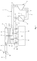
- a fresh gas system 1 comprises a fresh gas line 2, in which a charging device 3 is arranged.
- the fresh gas system 1 is used to supply an internal combustion engine 4 with fresh gas, in particular air, wherein the internal combustion engine 4 and the fresh gas system 1 are preferably arranged in a motor vehicle.
- the charging device 3 is preferably a compressor of an exhaust gas turbocharger. Likewise, it is basically possible for the charging device 3 to be a compressor, e.g. a Roots blower, or any other means for charging the fresh gas act.
- the fresh gas system 1 also has a heat exchanger 5, which serves for cooling the charged fresh gas and is usually referred to as intercooler.
- the heat exchanger 5 is arranged downstream of the charging device 3 in the fresh gas line 2 for this purpose.
- the fresh gas system 1 may comprise a fresh gas filter 6, which contains a filter element 8 in a housing 7 for cleaning the fresh gas supplied to the internal combustion engine 4.
- the fresh gas system 1 has a fresh gas distributor 11, which virtually forms the outlet of the fresh gas line 2 and via which the fresh gas line 2 is connected to the internal combustion engine 4.
- the fresh gas system 1 still has an inlet 12, which virtually forms the inlet of the fresh gas line 2 and passes through the fresh gas from the environment into the fresh gas line 2.
- the charging device 3 divides the fresh gas system 1 into a high-pressure side, which lies downstream of the charging device 3 and extends from the charging device 3 up to and including the fresh gas distributor 11, as well as into a low-pressure side upstream of the charging device 3 and extending from the inlet 12 to the charging device 3.
- the pressure pulsations or the airborne sound of the internal combustion engine 4 is to be emitted via the fresh gas system 1 via its low-pressure side, in particular through its inlet 12 into the environment.
- the invention proposes to acoustically couple the high-pressure side with the low-pressure side.
- the acoustic coupling between low pressure side and high pressure side of the fresh gas system 1, bypassing the charging device 3 is realized in that the high pressure side and low pressure side are coupled to the gas-tight transmission of pressure pulsations transported in the fresh gas. This means that the im Fresh gas high pressure side existing pressure pulsations are transmitted in a suitable manner in the low pressure side fresh gas.
- the vibration capability of the wall 13 causes high pressure side pressure pulsations can stimulate the wall 13 to vibrate, wherein the vibrating wall 13 can simultaneously initiate pressure pulsations in the fresh gas low pressure side. Since the wall 13 is gas-tight, the pressure pulsations can be transmitted from the high-pressure side to the low-pressure side without gas exchange through the oscillatory wall.
- the wall 13 since the wall 13 is disposed outside of the charging device 3 in the fresh gas system 1, the transmission of the pressure pulsations, bypassing the charging device 3 takes place.
- the wall 13 may be a gas-tight membrane 14, which is either self-oscillating or in itself rigid and stiff, is held vibrationally.
- a vibratable membrane 14 with oscillatory mounting is conceivable.
- Both Fig. 2 to 6 is such a vibratory holder indicated and designated 15.
- the wall 13 and the membrane 14 forms in two different components of the fresh gas system 1, namely here the fresh gas manifold 11 and the fresh gas filter 6 a common wall section.
- a housing 16 of the fresh gas distributor 11 is installed directly with the housing 7 of the fresh gas filter 6, such that a common wall section is formed, which then forms or includes the said wall 13 or the membrane 14.
- the housing 7 of the fresh gas filter 6 can be open on the clean side and be closed by mounting on the housing 16 of the fresh gas distributor 11 through said common wall section.
- the formation of the wall 13 or the membrane 14 by a common wall section in two different components of the fresh gas system 1 can be realized, for example, in a connection of the housing 7 of the fresh gas filter 6 to a housing 17 of the heat exchanger 5 or to the fresh gas line 2 downstream of the charging device 3 become.
- the fresh gas line 2 upstream of the charging device 3 together the housing 16 of the fresh gas distributor 11 or with the housing 17 of the heat exchanger 5 or with itself have a common wall portion which then forms said wall 13 and said membrane 14 or contains.
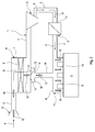
- a coupling line 18 extends between the high pressure side and the low pressure side and allows transmission of pressure pulsations over greater distances.
- the coupling line 18 is hollow, contains gas, so that it can spread airborne sound in it.
- the coupling line 18 can be acoustically coupled to said wall 13 or to said membrane 14.
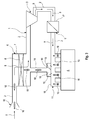
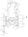
- a chamber 19 is expediently arranged in the region of the respective wall 13 or in the region of the respective membrane 14, which chamber encloses the respective wall 13 or the respective membrane 14 and which communicates with the coupling line 18.
- the coupling line 18 communicates on the one hand with the high-pressure side, here with the fresh gas distributor 11, while on the other hand communicates with the chamber 19, by means of the wall 13 or membrane 14 coming from the high-pressure side by means of the low pressure side, here on the fresh air filter 6 Transfer pressure pulsations to the low pressure side.
- the coupling line 18 communicates on the one hand with the low pressure side, here with the fresh gas filter 6, while on the other hand communicates with the chamber 19, via the arranged on the high pressure side, here at the fresh gas manifold 11 wall 13 ment.
- Membrane 14 to transfer pressure pulsations from the high pressure side to the low pressure side.
- the coupling line communicates 18 high-pressure side and low-pressure side each with a chamber 19, wherein the one chamber 19 encloses a on the high pressure side, here, for example, the fresh gas manifold 11, wall 13 and membrane 14, while the other chamber 19 one on the low pressure side, here on the fresh gas filter 6, arranged wall 13 and membrane 14 encloses.
- the fresh gas system 1 is equipped with a coupling device 20.
- This coupling device 20 has a housing 21.
- This housing 21 is incorporated in the coupling line 18 and contains a vibratory wall 13 and a vibrating membrane 14.
- the wall 13 and the membrane 14 separates in the housing 21 two chambers 19 gas-tight from each other, each of these chambers 19, the wall 13 and the membrane 14 encloses.
- the one chamber 19 communicates with the high-pressure side via a portion of the coupling line 18 and thereby forms a high-pressure side chamber 19.
- the other chamber 19 communicates via a corresponding one
- the airborne noise generated by it 10 passes high pressure side through the coupling line 18 in the high-pressure side chamber 19 and energizes the wall 13 and the diaphragm 14 to oscillate , These vibrations generate in the low-pressure side chamber 19 corresponding pressure pulsations, which spread over the low-pressure side coupling line 18 in the low pressure side.
- the respective chamber 19 can form, in particular together with the respective coupling line 18, a resonator, in particular a Helmholtz resonator, which can be tuned with regard to a desired sound pattern.
- low-pressure side and high-pressure side connection points are mentioned purely by way of example.
- To form the oscillatory wall 13 and the oscillatory membrane 14 are preferably relatively large wall sections of corresponding components of the fresh gas system 1. These are preferably housing sections, such as the fresh gas manifold 11 and the fresh gas filter 6 in the embodiments of Fig. 2 to 4 , As a result, the selection for the positioning of the respective coupling points is somewhat limited.
- the use of the coupling line 18 results in improved possibilities, since the coupling line 18 itself with a comparatively small-area connection point to communicate with the high pressure side or with the low pressure side manages.
- the embodiment shown makes it possible to connect the coupling line 18 on the high pressure side and the low pressure side with relatively small connection points, since the comparatively large wall 13 or membrane 14 is arranged in the coupling device 20, which can be positioned independently of the aforementioned attachment points of the coupling line 18.
- the coupling line 18 also to the fresh gas line 2 downstream of the charging device 3 and here additionally downstream of the heat exchanger 5 can be connected.
- the wall 13 or the membrane 14 is formed by a wall section of the housing 17 of the heat exchanger 5.
- the chamber 19 surrounds this wall 13 or membrane 14 and is connected via the coupling line 18 to the fresh gas line 2 upstream of the charging device 3 and preferably downstream of the fresh gas filter 6.
- acoustic coupling takes place with the aid of the coupling line 18, which communicates with the low-pressure side and / or with the high-pressure side for this purpose.
- a communicating connection is understood to mean an open connection, which in principle enables a gas exchange.
- the transmission of the pressure pulsations of the high pressure side on the Low pressure side takes place within the coupling line 18 in the form of airborne sound.
- a coupling body 22 is provided, which is coupled on the one hand to the high-pressure side and on the other hand to the low-pressure side for the transmission of pressure pulsations transported in the fresh gas.
- This coupling body 22 is designed so that it forms a structure-borne sound bridge between the high pressure side and the low pressure side.
- the body shift propagation in the coupling body 22 is indicated by a broken arrow 23.
- the coupling body 22 is preferably connected to a wall 13 or membrane 14 for vibration transmission arranged on the high-pressure side, here on the fresh-gas distributor 11.
- the coupling body 22 is connected to one of the low pressure side, here at the fresh gas filter 6, arranged wall 13 and membrane 14 for vibration transmission.
- the coupling body 22 operates as follows: The pressure pulsations of the high-pressure side rain on the high-pressure side wall 13 and membrane 14 to the coupling body 22 to vibrations, which transmits this as structure-borne noise on the low-pressure side wall 13 and membrane 14, whereby these at the low pressure side, the corresponding Pressure pulsations generated.
- the coupling body 22 is made comparatively stiff or rigid.
Landscapes
- Engineering & Computer Science (AREA)
- Chemical & Material Sciences (AREA)
- Combustion & Propulsion (AREA)
- Mechanical Engineering (AREA)
- General Engineering & Computer Science (AREA)
- Physics & Mathematics (AREA)
- Thermal Sciences (AREA)
- Acoustics & Sound (AREA)
- Multimedia (AREA)
- Pipe Accessories (AREA)
- Filling Or Discharging Of Gas Storage Vessels (AREA)
Abstract
Description
- Die vorliegende Erfindung betrifft eine Frischgasanlage für eine Brennkraftmaschine, insbesondere in einem Kraftfahrzeug.
- Brennkraftmaschinen erzeugen im Betrieb Geräusche, die unter anderem über die Frischgasanlage in die Umgebung emittiert werden. Dabei sind die Fahrzeughersteller bemüht, die Schallemissionen hinsichtlich ihrer Lautstärke niedrig zu halten, während gleichzeitig versucht wird, die Schallemissionen hinsichtlich ihres Klangs entsprechend dem Charakter des Fahrzeugs zu formen, sogenanntes Sounddesign. Zur Leistungssteigerung von Brennkraftmaschinen ist es bekannt, in der Frischgasanlage eine Ladeeinrichtung anzuordnen. Insbesondere bei der Verwendung eines Abgasturboladers führt dessen Verdichter zu einer Behinderung oder Dämpfung der Schallausbreitung von der Brennkraftmaschine durch die Frischgasanlage, vor allem dann, wenn der Turbolader bei einem erhöhten Leistungsbedarf der Brennkraftmaschine zu deren Aufladung aktiviert ist. Da jedoch gerade bei erhöhter Motorleistung quasi als akustisches Feedback eine Schallemission mit einem charakteristischen Klangmuster erwünscht ist, ergibt sich hier ein Konflikt.
- Die vorliegende Erfindung beschäftigt sich mit dem Problem, für eine Frischgasanlage mit Ladeeinrichtung eine verbesserte Ausführungsform anzugeben, die insbesondere eine gezielte Schallemission in die Umgebung verbessert.
- Dieses Problem wird erfindungsgemäß durch den Gegenstand des unabhängigen Anspruchs gelöst. Vorteilhafte Ausführungsformen sind Gegenstand der abhängigen Ansprüche.
- Die Erfindung beruht auf dem allgemeinen Gedanken, die Hochdruckseite der Frischgasanlage mit der Niederdruckseite der Frischgasanlage unter Umgehung der Ladeeinrichtung akustisch zu koppeln. Hierdurch ist der dämpfende bzw. behindernde Einfluss der Ladeeinrichtung bei der Schallausbreitung durch die Frischgasanlage erheblich reduziert. Der von der Brennkraftmaschine erzeugte Schall kann bei der erfindungsgemäßen Bauweise von der Hochdruckseite auf die Niederdruckseite gelangen, ohne dabei durch die Ladeeinrichtung zu müssen. In der Folge kann der gewünschte Schall an der Niederdruckseite, vorzugsweise über einen Einlauf der Frischgasleitung in die Umgebung emittiert werden. Erreicht wird dies bei der Erfindung durch eine Kopplung zwischen Hochdruckseite und Niederdruckseite, die eine gasdichte Übertragung von im Frischgas transportierten Druckpulsationen ermöglicht. Dabei sind die im Frischgas transportierten Druckpulsationen der von der Brennkraftmaschine hochdruckseitig in die Frischgsanlage eingeleitete Luftschall. Die Übertragung der Druckpulsationen erfolgt gasdicht, das bedeutet, dass es bei dieser Übertragung zu keinem Gasaustausch und zu keiner Gasströmung zwischen der Hochdruckseite und der Niederdruckseite kommt. In der Folge findet insbesondere auch kein Druckausgleich zwischen Hochdruckseite und Niederdruckseite statt.
- Gemäß einer vorteilhaften Ausführungsform erfolgt die Druckpulsationen übertragende Kopplung mittels wenigstens einer schwingungsfähigen, gasdichten Wand, die einerseits die Hochdruckseite und andererseits die Niederdruckseite begrenzt. Unter einer schwingungsfähigen Wand wird im vorliegenden Zusammenhang eine Wand verstanden, die hochdruckseitig durch Druckpulsationen zu Schwingungen anregbar ist und die durch ihre Schwingungen Druckpulsationen in die Niederdruckseite einleitet. Vorzugsweise handelt es sich bei dieser schwingungsfähigen Wand um eine gasdichte Membran, die schwingungsfähig ausgestaltet und/oder schwingungsfähig gehalten ist. Üblicherweise existiert innerhalb einer Frischgasanlage keine Wand, die einerseits die Hochdruckseite und andererseits die Niederdruckseite begrenzt. Die Trennung zwischen Hochdruckseite und Niederdruckseite erfolgt innerhalb der Frischgasanlage durch die in der Frischgasleitung angeordnete Ladeeinrichtung. Die zur akustischen Kopplung dienende Wand bzw. Membran ist jedoch außerhalb der Ladeeinrichtung angeordnet. Hierdurch ermöglicht besagte Wand bzw. Membran die akustische Umgehung der Ladeeinrichtung, um die gewünschte Schallübertragung zwischen Hochdruckseite und Niederdruckseite zu erzielen.
- Weitere wichtige Merkmale und Vorteile der Erfindung ergeben sich aus den Unteransprüchen, aus den Zeichnungen und aus der zugehörigen Figurenbeschreibung anhand der Zeichnungen.
- Es versteht sich, dass die vorstehend genannten und die nachstehend noch zu erläuternden Merkmale nicht nur in der jeweils angegebenen Kombination, sondern auch in anderen Kombinationen oder in Alleinstellung verwendbar sind, ohne den Rahmen der vorliegenden Erfindung zu verlassen.
- Bevorzugte Ausführungsbeispiele der Erfindung sind in den Zeichnungen dargestellt und werden in der nachfolgenden Beschreibung näher erläutert, wobei sich gleiche Bezugszeichen auf gleiche oder ähnliche oder funktional gleiche Bauteile beziehen.
- Es zeigen, jeweils schematisch,
- Fig. 1 bis 7
- jeweils eine stark vereinfachte, schaltplanartige Prinzipdarstellung einer Frischgasanlage bei verschiedenen Ausführungsformen.
- Entsprechend den
Fig. 1 bis 7 umfasst eine Frischgasanlage 1 eine Frischgasleitung 2, in der eine Ladeeinrichtung 3 angeordnet ist. Die Frischgasanlage 1 dient zur Versorgung einer Brennkraftmaschine 4 mit Frischgas, insbesondere Luft, wobei die Brennkraftmaschine 4 und die Frischgasanlage 1 vorzugsweise in einem Kraftfahrzeug angeordnet sind. - Die Ladeeinrichtung 3 ist vorzugsweise ein Verdichter eines Abgasturboladers. Ebenso ist es grundsätzlich möglich, dass es sich bei der Ladeeinrichtung 3 um einen Kompressor, z.B. ein Roots-Gebläse, oder um eine beliebige andere Einrichtung zur Aufladung des Frischgases handeln. Im gezeigten Beispiel weist die Frischgasanlage 1 außerdem einen Wärmeübertrager 5 auf, der zur Kühlung des aufgeladenen Frischgases dient und üblicherweise als Ladeluftkühler bezeichnet wird. Der Wärmeübertrager 5 ist hierzu stromab der Ladeeinrichtung 3 in der Frischgasleitung 2 angeordnet. Außerdem kann die Frischgasanlage 1 ein Frischgasfilter 6 aufweisen, das in einem Gehäuse 7 ein Filterelement 8 zur Reinigung des der Brennkraftmaschine 4 zugeführten Frischgases enthält.
- Die Frischgasanlage 1 weist einen Frischgasverteiler 11 auf, der quasi den Auslass der Frischgasleitung 2 bildet und über den die Frischgasleitung 2 an die Brennkraftmaschine 4 angeschlossen ist. Die Frischgasanlage 1 weist noch einen Einlauf 12 auf, der quasi den Einlass der Frischgasleitung 2 bildet und durch den Frischgas aus der Umgebung in die Frischgasleitung 2 gelangt. Die Ladeeinrichtung 3 unterteilt die Frischgasanlage 1 in eine Hochdruckseite, die stromab der Ladeeinrichtung 3 liegt und sich von der Ladeeinrichtung 3 bis einschließlich zum Frischgasverteiler 11 erstreckt, sowie in eine Niederdruckseite, die stromauf der Ladeeinrichtung 3 liegt und die sich vom Einlauf 12 bis zur Ladeeinrichtung 3 erstreckt.
- Die sich im Betrieb der Brennkraftmaschine 4 einstellende Gasströmung ist in den Figuren durch Pfeile 9 symbolisiert. Des Weiteren ist durch mit Querstrichen versehene Pfeile 10 Luftschall angedeutet, der im Betrieb der Brennkraftmaschine 4 von dieser in die Hochdruckseite der Frischgasanlage 1 eingeleitet wird. Dieser Luftschall 10 besteht an sich aus im Frischgas transportierten Druckpulsationen, die im folgenden ebenfalls mit 10 bezeichnet werden.
- Die Druckpulsationen bzw. der Luftschall der Brennkraftmaschine 4 soll über die Frischgasanlage 1 über deren Niederdruckseite, insbesondere durch deren Einlauf 12 in die Umgebung emittiert werden. Um hierbei den störenden Einfluss der Ladeeinrichtung 3 zu reduzieren, schlägt die Erfindung vor, die Hochdruckseite mit der Niederdruckseite akustisch zu koppeln. Im folgenden werden nun einzelne, beispielhafte Lösungsvorschläge näher erläutert, wobei die gezeigten Ausführungsformen rein exemplarisch und ohne Beschränkung der Allgemeinheit zu verstehen sind.
- Bei den Ausführungsformen der
Fig. 1 bis 7 wird die akustische Kopplung zwischen Niederdruckseite und Hochdruckseite der Frischgasanlage 1 unter Umgehung der Ladeeinrichtung 3 dadurch realisiert, dass Hochdruckseite und Niederdruckseite zur gasdichten Übertragung von im Frischgas transportierten Druckpulsationen gekoppelt sind. Das bedeutet, dass die im Frischgas hochdruckseitig vorhandenen Druckpulsationen auf geeignete Weise in das niederdruckseitige Frischgas übertragen werden. - Bei den hier gezeigten Ausführungsformen erfolgt die Druckpulsationen übertragende Kopplung zwischen Hochdruckseite und Niederdruckseite mittels wenigstens einer Wand 13, die gasdicht ist, die schwingungsfähig ist und die einerseits die Hochdruckseite und andererseits die Niederdruckseite begrenzt. Das bedeutet, dass besagte Wand 13 an ihrer einen Seite mit dem Hochdruck und an ihrer anderen Seite mit dem Niederdruck beaufschlagt ist. Die Schwingungsfähigkeit der Wand 13 bewirkt, dass hochdruckseitige Druckpulsationen die Wand 13 zu Schwingungen anregen können, wobei die schwingende Wand 13 gleichzeitig niederdruckseitig Druckpulsationen in das Frischgas einleiten kann. Da die Wand 13 gasdicht ist, lassen sich durch die schwingungsfähige Wand die Druckpulsationen ohne Gasaustausch von der Hochdruckseite auf die Niederdruckseite übertragen. Da außerdem die Wand 13 außerhalb der Ladeeinrichtung 3 in der Frischgasanlage 1 angeordnet ist, erfolgt die Übertragung der Druckpulsationen unter Umgehung der Ladeeinrichtung 3.
- Vorzugsweise kann es sich bei der Wand 13 um eine gasdichte Membran 14 handeln, die entweder selbst schwingungsfähig ausgestaltet ist oder an sich starr und steif ist, dafür schwingungsfähig gehalten ist. Ebenso ist eine schwingungsfähige Membran 14 mit schwingungsfähiger Halterung denkbar.
- Bei den
Fig. 2 bis 6 ist eine derartige schwingungsfähige Halterung angedeutet und mit 15 bezeichnet. - Bei der in
Fig. 1 gezeigten Ausführungsform bildet die Wand 13 bzw. die Membran 14 bei zwei verschiedenen Komponenten der Frischgasanlage 1, nämlich hier beim Frischgasverteiler 11 und beim Frischgasfilter 6 einen gemeinsamen Wandabschnitt. Zu diesem Zweck ist ein Gehäuse 16 des Frischgasverteilers 11 direkt mit dem Gehäuse 7 des Frischgasfilters 6 verbaut, derart, dass ein gemeinsamer Wandabschnitt entsteht, der dann die besagte Wand 13 bzw. die Membran 14 bildet oder beinhaltet. Beispielsweise kann das Gehäuse 7 des Frischgasfilters 6 reinseitig offen sein und durch die Montage am Gehäuse 16 des Frischgasverteilers 11 durch besagten gemeinsamen Wandabschnitt verschlossen werden. - Die Ausbildung der Wand 13 bzw. der Membran 14 durch einen gemeinsamen Wandabschnitt bei zwei verschiedenen Komponenten der Frischgasanlage 1 kann beispielsweise auch bei einer Anbindung des Gehäuses 7 des Frischgasfilters 6 an ein Gehäuse 17 des Wärmeübertragers 5 oder an die Frischgasleitung 2 stromab der Ladeeinrichtung 3 realisiert werden. Ebenso kann die Frischgasleitung 2 stromauf der Ladeeinrichtung 3 zusammen dem Gehäuse 16 des Frischgasverteilers 11 oder mit dem Gehäuse 17 des Wärmeübertragers 5 oder mit sich selbst einen gemeinsamen Wandabschnitt aufweisen, der dann besagte Wand 13 bzw. besagte Membran 14 bildet bzw. enthält.
- Bei den Ausführungsformen der
Fig. 2 bis 6 weist die Frischgasanlage 1 zur Realisierung der akustischen Kopplung zwischen Hochdruckseite und Niederdruckseite eine Kopplungsleitung 18 auf. Die Kopplungsleitung 18 erstreckt sich dabei zwischen der Hochdruckseite und der Niederdruckseite und ermöglicht eine Übertragung von Druckpulsationen über größere Entfernungen. Die Kopplungsleitung 18 ist hierzu hohl, enthält Gas, so dass sich in ihr Luftschall ausbreiten kann. Die Kopplungsleitung 18 kann hierzu mit besagter Wand 13 bzw. mit besagter Membran 14 akustisch gekoppelt sein. Hierzu ist im Bereich der jeweiligen Wand 13 bzw. im Bereich der jeweiligen Membran 14 zweckmäßig eine Kammer 19 angeordnet, welche die jeweilige Wand 13 bzw. die jeweilige Membran 14 einfasst und welche mit der Kopplungsleitung 18 kommuniziert. Bei der inFig. 2 gezeigten Ausführungsform kommuniziert die Kopplungsleitung 18 einerseits mit der Hochdruckseite, hier mit dem Frischgasverteiler 11, während sie andererseits mit der Kammer 19 kommuniziert, um mittels der an der Niederdruckseite, hier am Frischluftfilter 6, angeordneten Wand 13 bzw. Membran 14 die von der Hochdruckseite kommenden Druckpulsationen auf die Niederdruckseite zu übertragen. - Bei der in
Fig. 3 gezeigten Ausführungsform kommuniziert die Kopplungsleitung 18 einerseits mit der Niederdruckseite, hier mit dem Frischgasfilter 6, während sie andererseits mit der Kammer 19 kommuniziert, um über die an der Hochdruckseite, hier am Frischgasverteiler 11 angeordnete Wand 13 bzw. - Membran 14 Druckpulsationen von der Hochdruckseite auf die Niederdruckseite zu übertragen.
- Während die in den
Fig. 1 bis 3 undFig. 5 ,6 gezeigten Ausführungsformen jeweils mit einer einzigen Wand 13 bzw. mit einer einzigen Membran 14 zur Realisierung der akustischen Kopplung arbeiten, zeigtFig. 4 eine Ausführungsform, bei der die akustische Kopplung mit Hilfe von zwei schwingungsfähigen Wänden 13 bzw. mit Hilfe von zwei Membranen 14 realisiert wird. Demnach kommuniziert die Kopplungsleitung 18 hochdruckseitig und niederdruckseitig jeweils mit einer Kammer 19, wobei die eine Kammer 19 eine an der Hochdruckseite, hier beispielsweise am Frischgasverteiler 11, angeordnete Wand 13 bzw. Membran 14 umschließt, während die andere Kammer 19 eine an der Niederdruckseite, hier am Frischgasfilter 6, angeordnete Wand 13 bzw. Membran 14 umschließt. - Bei der in
Fig. 5 gezeigten besonderen Ausführungsform ist die Frischgasanlage 1 mit einer Kopplungseinrichtung 20 ausgestattet. Diese Kopplungseinrichtung 20 weist ein Gehäuse 21 auf. Dieses Gehäuse 21 ist in die Kopplungsleitung 18 eingebunden und enthält eine schwingungsfähige Wand 13 bzw. eine schwingungsfähige Membran 14. Die Wand 13 bzw. die Membran 14 trennt im Gehäuse 21 zwei Kammern 19 gasdicht voneinander, wobei jede dieser Kammern 19 die Wand 13 bzw. die Membran 14 umschließt. Die eine Kammer 19 kommuniziert über einen Abschnitt der Kopplungsleitung 18 mit der Hochdruckseite und bildet dadurch eine hochdruckseitige Kammer 19. Die andere Kammer 19 kommuniziert über einen entsprechenden Abschnitt der Kopplungsleitung 18 mit der Niederdruckseite und bildet dementsprechend eine niederdruckseitige Kammer 19. Im Betrieb der Brennkraftmaschine 4 gelangt der von ihr erzeugte Luftschall 10 hochdruckseitig durch die Kopplungsleitung 18 in die hochdruckseitige Kammer 19 und regt die Wand 13 bzw. die Membran 14 zu Schwingungen an. Diese Schwingungen erzeugen in der niederdruckseitigen Kammer 19 korrespondierende Druckpulsationen, die sich über die niederdruckseitige Kopplungsleitung 18 in der Niederdruckseite ausbreiten. - Die jeweilige Kammer 19 kann, insbesondere zusammen mit der jeweiligen Kopplungsleitung 18, einen Resonator, insbesondere einen Helmholtzresonator bilden, der hinsichtlich eines gewünschten Klangbildes abgestimmt sein kann.
- Es ist klar, dass die in den
Fig. 2 bis 4 gezeigte niederdruckseitigen und hochdruckseitigen Anbindungsstellen rein exemplarisch genannt sind. Zur Ausbildung der schwingungsfähigen Wand 13 bzw. der schwingungsfähigen Membran 14 eignen sich bevorzugt relativ großflächige Wandabschnitte von entsprechenden Komponenten der Frischgasanlage 1. Bevorzugt handelt es sich hierbei um Gehäuseabschnitte, so z.B. beim Frischgasverteiler 11 und beim Frischgasfilter 6 bei den Ausführungsformen derFig. 2 bis 4 . Dadurch ist die Auswahl für die Positionierung der jeweiligen Kopplungsstellen etwas eingeschränkt. Durch die Verwendung der Kopplungsleitung 18 ergeben sich verbesserte Möglichkeiten, da die Kopplungsleitung 18 selbst mit einer vergleichsweise kleinflächigen Anbindungsstelle zur Kommunikation mit der Hochdruckseite bzw. mit der Niederdruckseite auskommt. Die Verwendung der Kopplungseinrichtung 20 gemäß der inFig. 5 gezeigten Ausführungsform ermöglicht es, die Kopplungsleitung 18 hochdruckseitig und niederdruckseitig mit relativ kleinen Anbindungsstellen kommunizierend anzuschließen, da die vergleichsweise großflächige Wand 13 bzw. Membran 14 in der Kopplungseinrichtung 20 angeordnet ist, die von den genannten Anbindungsstellen der Kopplungsleitung 18 grundsätzlich unabhängig positioniert werden kann. - Beispielhaft ist in
Fig. 5 gezeigt, dass die Kopplungsleitung 18 auch an die Frischgasleitung 2 stromab der Ladeeinrichtung 3 und hier zusätzlich stromab des Wärmeübertragers 5 anschließbar ist. Bei der inFig. 6 gezeigten Ausführungsform ist die Wand 13 bzw. die Membran 14 durch einen Wandabschnitt des Gehäuses 17 des Wärmeübertragers 5 gebildet. Die Kammer 19 umschließt diese Wand 13 bzw. Membran 14 und ist über die Kopplungsleitung 18 an die Frischgasleitung 2 stromauf der Ladeeinrichtung 3 und vorzugsweise stromab des Frischgasfilters 6 angeschlossen. - Bei den Ausführungsformen der
Fig. 2 bis 6 erfolgt die akustische Kopplung mit Hilfe der Kopplungsleitung 18, die hierzu mit der Niederdruckseite und/oder mit der Hochdruckseite kommuniziert. Unter einer kommunizierenden Verbindung wird im vorliegenden Zusammenhang eine offene Anbindung verstanden, die grundsätzlich einen Gasaustausch ermöglicht. Die Übertragung der Druckpulsationen der Hochdruckseite auf die Niederdruckseite erfolgt dabei innerhalb der Kopplungsleitung 18 in Form von Luftschall. - Bei der in
Fig. 7 gezeigten Ausführungsform ist ein Kopplungskörper 22 vorgesehen, der einerseits mit der Hochdruckseite und andererseits mit der Niederdruckseite zur Übertragung von im Frischgas transportierten Druckpulsationen gekoppelt ist. Dieser Kopplungskörper 22 ist dabei so ausgestaltet, dass er eine Körperschallbrücke zwischen der Hochdruckseite und der Niederdruckseite bildet. Die Körperschaltausbreitung im Kopplungskörper 22 ist durch einen unterbrochenen Pfeil 23 angedeutet. Vorzugsweise ist der Kopplungskörper 22 hierzu mit einer an der Hochdruckseite, hier am Frischgasverteiler 11, angeordneten Wand 13 bzw. Membran 14 zur Schwingungsübertragung verbunden. Ebenso ist der Kopplungskörper 22 mit einer der Niederdruckseite, hier am Frischgasfilter 6, angeordneten Wand 13 bzw. Membran 14 zur Schwingungsübertragung verbunden. Der Kopplungskörper 22 arbeitet wie folgt: Die Druckpulsationen der Hochdruckseite regen über die hochdruckseitige Wand 13 bzw. Membran 14 den Kopplungskörper 22 zu Schwingungen an, die dieser als Körperschall auf die niederdruckseitige Wand 13 bzw. Membran 14 überträgt, wodurch diese an der Niederdruckseite die entsprechenden Druckpulsationen erzeugt. Der Kopplungskörper 22 ist vergleichsweise steif oder starr ausgestaltet.
Claims (11)
- Frischgasanlage für eine Brennkraftmaschine, insbesondere in einem Kraftfahrzeug,- mit einer Frischgasleitung (2), in der eine Ladeeinrichtung (3) angeordnet ist,- wobei eine stromab der Ladeeinrichtung (3) liegende Hochdruckseite der Frischgasanlage (1) mit einer stromauf der Ladeeinrichtung (3) liegenden Niederdruckseite der Frischgasanlage (1) zur gasdichten Übertragung von im Frischgas transportierten Druckpulsationen gekoppelt ist.
- Frischgasanlage nach Anspruch 1,
dadurch gekennzeichnet,
dass die Druckpulsationen übertragende Kopplung mittels wenigstens einer schwingungsfähigen, gasdichten Wand (13) erfolgt, die einerseits die Hochdruckseite und andererseits die Niederdruckseite begrenzt. - Frischgasanlage nach Anspruch 2,
dadurch gekennzeichnet,
dass die schwingungsfähige Wand (13) oder zumindest eine schwingungsfähige Wand (13) eine gasdichte Membran (14) ist, die schwingungsfähig ausgestaltet und/oder schwingungsfähig gehalten ist. - Frischgasanlage nach Anspruch 2 oder 3,
dadurch gekennzeichnet,- dass die Wand (13) oder die Membran (14) bei einer Komponente (2, 5, 6, 11, 12) der Frischgasanlage (1) durch einen Wandabschnitt gebildet ist, oder- dass die Wand (13) oder die Membran (14) bei zwei verschiedenen Komponenten (2, 5, 6, 16, 12) der Frischgasanlage (1) durch einen gemeinsamen Wandabschnitt gebildet ist. - Frischgasanlage nach einem der Ansprüche 2 bis 4,
dadurch gekennzeichnet,
dass die Wand (13) oder die Membran (14) durch einen Wandabschnitt eines Gehäuses (7) eines niederdruckseitig in der Frischgasleitung (2) angeordneten Frischgasfilters (6) und/oder eines Gehäuses (16) eines die Frischgasleitung (2) mit der Brennkraftmaschine (4) verbindenden Frischgasverteilers (11) und/oder eines Gehäuses (17) eines hochdruckseitig in der Frischgasleitung (2) angeordneten, zur Kühlung des aufgeladenen Frischgases dienenden Wärmeübertragers (5) und/oder der Frischgasleitung (2) gebildet ist. - Frischgasanlage nach einem der Ansprüche 1 bis 5,
dadurch gekennzeichnet,
dass eine Kopplungsleitung (18) vorgesehen ist, die sich zwischen der Hochdruckseite und der Niederdruckseite zur Übertragung von Druckpulsationen erstreckt. - Frischgasanlage nach Anspruch 6,
dadurch gekennzeichnet,- dass die Kopplungsleitung (18) einerseits mit der Hochdruckseite kommuniziert und andererseits zur Übertragung der im Frischgas transportierten Druckpulsationen mit der Niederdruckseite gekoppelt ist, oder- dass die Kopplungsleitung (18) einerseits zur Übertragung der im Frischgas transportierten Druckpulsationen mit der Hochdruckseite gekoppelt ist und andererseits mit der Niederdruckseite kommuniziert, oder- dass die Kopplungsleitung (18) einerseits zur Übertragung der im Frischgas transportierten Druckpulsationen mit der Hochdruckseite gekoppelt ist und andererseits zur Übertragung der im Frischgas transportierten Druckpulsationen mit der Niederdruckseite gekoppelt ist. - Frischgasanlage nach einem der Ansprüche 2 bis 5 und nach Anspruch 6 oder 7,
dadurch gekennzeichnet,
dass die Kopplungsleitung (18) mit wenigstens einer Kammer (19) kommuniziert, welche die Wand (13) oder die Membran (14) einfasst. - Frischgasanlage nach einem der Ansprüche 2 bis 8,
dadurch gekennzeichnet,- dass eine Kopplungseinrichtung (20) vorgesehen ist, die ein Gehäuse (21) aufweist, das in eine Kopplungsleitung (18) eingebunden ist und in dem eine schwingungsfähige Wand (13) oder eine schwingungsfähig ausgestaltete oder schwingungsfähig gehaltene Membran (14) zwei Kammern (19) gasdicht voneinander trennt,- dass die Wand (13) oder die Membran (14) die beiden Kammern (19) zur Übertragung von im Frischgas transportierten Druckpulsationen koppelt,- dass die eine Kammer (19) über die Kopplungsleitung (18) mit der Hochdruckseite kommuniziert, während die andere Kammer (19) über die Kopplungsleitung (18) mit der Niederdruckseite kommuniziert. - Frischgasanlage nach einem der Ansprüche 1 bis 5,
dadurch gekennzeichnet,
dass ein Kopplungskörper (22) vorgesehen ist, der einerseits mit der Hochdruckseite und andererseits mit der Niederdrucksite zur Übertragung von im Frischgas transportierten Druckpulsationen gekoppelt ist und der als Körperschallbrücke zwischen Hochdruckseite und Niederdruckseite ausgestaltet ist. - Frischgasanlage nach Anspruch 10 und einem der Ansprüche 2 bis 5,
dadurch gekennzeichnet,
dass der Kopplungskörper (22) mit einer hochdruckseitigen Wand (13) oder Membran (14) und mit einer niederdruckseitigen Wand (13) oder Membran (14) zur Schwingungsübertragung verbunden ist.
Applications Claiming Priority (1)
| Application Number | Priority Date | Filing Date | Title |
|---|---|---|---|
| DE102006058074A DE102006058074A1 (de) | 2006-12-07 | 2006-12-07 | Frischgasanlage für eine Brennkraftmaschine |
Publications (2)
| Publication Number | Publication Date |
|---|---|
| EP1936177A1 true EP1936177A1 (de) | 2008-06-25 |
| EP1936177B1 EP1936177B1 (de) | 2010-02-17 |
Family
ID=39149322
Family Applications (1)
| Application Number | Title | Priority Date | Filing Date |
|---|---|---|---|
| EP07122555A Ceased EP1936177B1 (de) | 2006-12-07 | 2007-12-06 | Frischgasanlage für eine Brennkraftmaschine |
Country Status (2)
| Country | Link |
|---|---|
| EP (1) | EP1936177B1 (de) |
| DE (2) | DE102006058074A1 (de) |
Citations (4)
| Publication number | Priority date | Publication date | Assignee | Title |
|---|---|---|---|---|
| DE10212257A1 (de) * | 2001-03-21 | 2002-09-26 | Daimler Chrysler Ag | Vorrichtung zur Geräuschgestaltung bei einem Kraftfahrzeug |
| DE10116169A1 (de) * | 2001-03-31 | 2002-10-17 | Mahle Filtersysteme Gmbh | Schallübertragungsvorrichtung für ein Kraftfahrzeug |
| EP1306829A2 (de) * | 2001-10-27 | 2003-05-02 | Filterwerk Mann + Hummel Gmbh | Vorrichtung zur Übertragung von Brennkraftmaschinengeräuschen |
| WO2003102917A1 (de) * | 2002-05-29 | 2003-12-11 | Daimlerchrysler Ag | Vorrichtung zur geräuschgestaltung bei einem kraftfahrzeug |
Family Cites Families (2)
| Publication number | Priority date | Publication date | Assignee | Title |
|---|---|---|---|---|
| DE1052169B (de) * | 1954-04-20 | 1959-03-05 | Sigismond Wilman | Ansauggeraeuschdaempfer |
| DE10222507A1 (de) * | 2001-09-24 | 2003-05-08 | Daimler Chrysler Ag | Vorrichtung zur Geräuschgestaltung bei einem Kraftfahrzeug |
-
2006
- 2006-12-07 DE DE102006058074A patent/DE102006058074A1/de not_active Withdrawn
-
2007
- 2007-12-06 EP EP07122555A patent/EP1936177B1/de not_active Ceased
- 2007-12-06 DE DE502007002857T patent/DE502007002857D1/de active Active
Patent Citations (4)
| Publication number | Priority date | Publication date | Assignee | Title |
|---|---|---|---|---|
| DE10212257A1 (de) * | 2001-03-21 | 2002-09-26 | Daimler Chrysler Ag | Vorrichtung zur Geräuschgestaltung bei einem Kraftfahrzeug |
| DE10116169A1 (de) * | 2001-03-31 | 2002-10-17 | Mahle Filtersysteme Gmbh | Schallübertragungsvorrichtung für ein Kraftfahrzeug |
| EP1306829A2 (de) * | 2001-10-27 | 2003-05-02 | Filterwerk Mann + Hummel Gmbh | Vorrichtung zur Übertragung von Brennkraftmaschinengeräuschen |
| WO2003102917A1 (de) * | 2002-05-29 | 2003-12-11 | Daimlerchrysler Ag | Vorrichtung zur geräuschgestaltung bei einem kraftfahrzeug |
Also Published As
| Publication number | Publication date |
|---|---|
| EP1936177B1 (de) | 2010-02-17 |
| DE102006058074A1 (de) | 2008-06-19 |
| DE502007002857D1 (de) | 2010-04-01 |
Similar Documents
| Publication | Publication Date | Title |
|---|---|---|
| DE102014204637B4 (de) | Ansauggeräuschübertragungsvorrichtung | |
| EP2130201B1 (de) | Helmholtz-resonator | |
| DE10212257B4 (de) | Vorrichtung zur Geräuschgestaltung bei einem Kraftfahrzeug | |
| DE102008005085B4 (de) | Verstellbare Helmholtz-Resonatoranordnung | |
| DE602006000314T2 (de) | Vorrichtung zur Geräuschverstärkung | |
| DE202018006874U1 (de) | Akustisch abgestimmter Schalldämpfer | |
| DE10217760B4 (de) | Frischgasversorgungsanlage für eine Brennkraftmaschine | |
| EP2444605B1 (de) | Schalldämpfer | |
| DE102012108804A1 (de) | Kompakter Niederfrequenzresonator | |
| DE19704376A1 (de) | Luftfilteranordnung | |
| EP1306829B1 (de) | Vorrichtung zur Übertragung von Brennkraftmaschinengeräuschen | |
| DE102008027290A1 (de) | Schalldämpfer für eine Abgasanlage | |
| DE202014104890U1 (de) | Einlasssystem mit Schalldämpfervorrichtung | |
| DE10042012A1 (de) | Vorrichtung zur Geräuschgestaltung bei einem Kraftfahrzeug | |
| DE10116169C2 (de) | Schallübertragungsvorrichtung für ein Kraftfahrzeug | |
| EP2273096A2 (de) | Brennkraftmaschine mit Ladeluftkühler | |
| EP1195499A2 (de) | Vorrichtung und Verfahren zur Reduzierung der Schallemission bei Verbrennungsmotoren und zu deren Diagnose | |
| EP1099045B1 (de) | Vorrichtung und verfahren zur reduzierung der schallemission bei verbrennungsmotoren und zu deren diagnose | |
| EP1741091B1 (de) | Vorrichtung zur schallkopplung zwischen einem ansaugtrakt und/oder motorraum und einem fahrzeuginnenraum eines kraftfahrzeuges | |
| EP1717433A9 (de) | Aktiver Ansaugschalldämpfer | |
| EP1936177B1 (de) | Frischgasanlage für eine Brennkraftmaschine | |
| DE10322570B4 (de) | Schalldämpfungsvorrichtung bei einem Kraftfahrzeug | |
| DE102010023649A1 (de) | Membranversteifung durch Verrippung für die Vorrichtung zur Übertragung des Motorengeräusches | |
| EP1431536A1 (de) | Schallwandler für ein Kraftfahrzeug | |
| DE10102923C1 (de) | Schallabstrahlvorrichtung für ein Kraftfahrzeug |
Legal Events
| Date | Code | Title | Description |
|---|---|---|---|
| PUAI | Public reference made under article 153(3) epc to a published international application that has entered the european phase |
Free format text: ORIGINAL CODE: 0009012 |
|
| AK | Designated contracting states |
Kind code of ref document: A1 Designated state(s): AT BE BG CH CY CZ DE DK EE ES FI FR GB GR HU IE IS IT LI LT LU LV MC MT NL PL PT RO SE SI SK TR |
|
| AX | Request for extension of the european patent |
Extension state: AL BA HR MK RS |
|
| 17P | Request for examination filed |
Effective date: 20081216 |
|
| AKX | Designation fees paid |
Designated state(s): DE FR GB |
|
| GRAP | Despatch of communication of intention to grant a patent |
Free format text: ORIGINAL CODE: EPIDOSNIGR1 |
|
| GRAS | Grant fee paid |
Free format text: ORIGINAL CODE: EPIDOSNIGR3 |
|
| GRAA | (expected) grant |
Free format text: ORIGINAL CODE: 0009210 |
|
| AK | Designated contracting states |
Kind code of ref document: B1 Designated state(s): DE FR GB |
|
| REG | Reference to a national code |
Ref country code: GB Ref legal event code: FG4D Free format text: NOT ENGLISH |
|
| REF | Corresponds to: |
Ref document number: 502007002857 Country of ref document: DE Date of ref document: 20100401 Kind code of ref document: P |
|
| PLBE | No opposition filed within time limit |
Free format text: ORIGINAL CODE: 0009261 |
|
| STAA | Information on the status of an ep patent application or granted ep patent |
Free format text: STATUS: NO OPPOSITION FILED WITHIN TIME LIMIT |
|
| 26N | No opposition filed |
Effective date: 20101118 |
|
| REG | Reference to a national code |
Ref country code: FR Ref legal event code: PLFP Year of fee payment: 9 |
|
| REG | Reference to a national code |
Ref country code: FR Ref legal event code: PLFP Year of fee payment: 10 |
|
| REG | Reference to a national code |
Ref country code: FR Ref legal event code: PLFP Year of fee payment: 11 |
|
| PGFP | Annual fee paid to national office [announced via postgrant information from national office to epo] |
Ref country code: GB Payment date: 20181221 Year of fee payment: 12 Ref country code: FR Payment date: 20181227 Year of fee payment: 12 |
|
| PGFP | Annual fee paid to national office [announced via postgrant information from national office to epo] |
Ref country code: DE Payment date: 20190228 Year of fee payment: 12 |
|
| REG | Reference to a national code |
Ref country code: DE Ref legal event code: R119 Ref document number: 502007002857 Country of ref document: DE |
|
| GBPC | Gb: european patent ceased through non-payment of renewal fee |
Effective date: 20191206 |
|
| PG25 | Lapsed in a contracting state [announced via postgrant information from national office to epo] |
Ref country code: FR Free format text: LAPSE BECAUSE OF NON-PAYMENT OF DUE FEES Effective date: 20191231 Ref country code: GB Free format text: LAPSE BECAUSE OF NON-PAYMENT OF DUE FEES Effective date: 20191206 Ref country code: DE Free format text: LAPSE BECAUSE OF NON-PAYMENT OF DUE FEES Effective date: 20200701 |