EP1935694A1 - Sealing profile, in particular for sealing a door against the bodywork of a motor vehicle - Google Patents
Sealing profile, in particular for sealing a door against the bodywork of a motor vehicle Download PDFInfo
- Publication number
- EP1935694A1 EP1935694A1 EP07118682A EP07118682A EP1935694A1 EP 1935694 A1 EP1935694 A1 EP 1935694A1 EP 07118682 A EP07118682 A EP 07118682A EP 07118682 A EP07118682 A EP 07118682A EP 1935694 A1 EP1935694 A1 EP 1935694A1
- Authority
- EP
- European Patent Office
- Prior art keywords
- sealing
- profile according
- sealing profile
- lip
- sealing lip
- Prior art date
- Legal status (The legal status is an assumption and is not a legal conclusion. Google has not performed a legal analysis and makes no representation as to the accuracy of the status listed.)
- Granted
Links
- 238000007789 sealing Methods 0.000 title claims abstract description 168
- 229920002725 thermoplastic elastomer Polymers 0.000 claims abstract description 6
- 229920002943 EPDM rubber Polymers 0.000 claims abstract description 5
- 239000000463 material Substances 0.000 claims abstract description 5
- 230000003014 reinforcing effect Effects 0.000 claims description 9
- 239000011248 coating agent Substances 0.000 claims description 5
- 238000000576 coating method Methods 0.000 claims description 5
- 238000001125 extrusion Methods 0.000 claims description 5
- 239000013536 elastomeric material Substances 0.000 claims description 4
- 230000001154 acute effect Effects 0.000 claims description 3
- 239000007769 metal material Substances 0.000 claims description 2
- 238000004519 manufacturing process Methods 0.000 description 5
- 238000001746 injection moulding Methods 0.000 description 3
- 230000007704 transition Effects 0.000 description 3
- 238000005452 bending Methods 0.000 description 2
- 230000000694 effects Effects 0.000 description 2
- 238000000465 moulding Methods 0.000 description 2
- 230000000007 visual effect Effects 0.000 description 2
- 229920000034 Plastomer Polymers 0.000 description 1
- 241001074085 Scophthalmus aquosus Species 0.000 description 1
- 239000002390 adhesive tape Substances 0.000 description 1
- 238000005266 casting Methods 0.000 description 1
- 230000008859 change Effects 0.000 description 1
- 238000001816 cooling Methods 0.000 description 1
- 229920001971 elastomer Polymers 0.000 description 1
- 239000000806 elastomer Substances 0.000 description 1
- 244000144992 flock Species 0.000 description 1
- 238000010438 heat treatment Methods 0.000 description 1
- 238000003780 insertion Methods 0.000 description 1
- 230000037431 insertion Effects 0.000 description 1
- 239000002184 metal Substances 0.000 description 1
- 238000000034 method Methods 0.000 description 1
- 239000004597 plastic additive Substances 0.000 description 1
- 230000008569 process Effects 0.000 description 1
- 125000006850 spacer group Chemical group 0.000 description 1
- 230000006641 stabilisation Effects 0.000 description 1
- 238000011105 stabilization Methods 0.000 description 1
- 230000008719 thickening Effects 0.000 description 1
- 238000004073 vulcanization Methods 0.000 description 1
Images

Classifications
-
- B—PERFORMING OPERATIONS; TRANSPORTING
- B60—VEHICLES IN GENERAL
- B60J—WINDOWS, WINDSCREENS, NON-FIXED ROOFS, DOORS, OR SIMILAR DEVICES FOR VEHICLES; REMOVABLE EXTERNAL PROTECTIVE COVERINGS SPECIALLY ADAPTED FOR VEHICLES
- B60J10/00—Sealing arrangements
- B60J10/80—Sealing arrangements specially adapted for opening panels, e.g. doors
- B60J10/86—Sealing arrangements specially adapted for opening panels, e.g. doors arranged on the opening panel
- B60J10/88—Sealing arrangements specially adapted for opening panels, e.g. doors arranged on the opening panel mounted on, or integral with, the glass-run seals
-
- B—PERFORMING OPERATIONS; TRANSPORTING
- B60—VEHICLES IN GENERAL
- B60J—WINDOWS, WINDSCREENS, NON-FIXED ROOFS, DOORS, OR SIMILAR DEVICES FOR VEHICLES; REMOVABLE EXTERNAL PROTECTIVE COVERINGS SPECIALLY ADAPTED FOR VEHICLES
- B60J10/00—Sealing arrangements
- B60J10/20—Sealing arrangements characterised by the shape
- B60J10/21—Sealing arrangements characterised by the shape having corner parts or bends
-
- B—PERFORMING OPERATIONS; TRANSPORTING
- B60—VEHICLES IN GENERAL
- B60J—WINDOWS, WINDSCREENS, NON-FIXED ROOFS, DOORS, OR SIMILAR DEVICES FOR VEHICLES; REMOVABLE EXTERNAL PROTECTIVE COVERINGS SPECIALLY ADAPTED FOR VEHICLES
- B60J10/00—Sealing arrangements
- B60J10/20—Sealing arrangements characterised by the shape
- B60J10/26—Sealing arrangements characterised by the shape characterised by the surface shape
- B60J10/265—Sealing arrangements characterised by the shape characterised by the surface shape the surface being primarily decorative
-
- B—PERFORMING OPERATIONS; TRANSPORTING
- B60—VEHICLES IN GENERAL
- B60J—WINDOWS, WINDSCREENS, NON-FIXED ROOFS, DOORS, OR SIMILAR DEVICES FOR VEHICLES; REMOVABLE EXTERNAL PROTECTIVE COVERINGS SPECIALLY ADAPTED FOR VEHICLES
- B60J10/00—Sealing arrangements
- B60J10/30—Sealing arrangements characterised by the fastening means
- B60J10/32—Sealing arrangements characterised by the fastening means using integral U-shaped retainers
-
- B—PERFORMING OPERATIONS; TRANSPORTING
- B60—VEHICLES IN GENERAL
- B60J—WINDOWS, WINDSCREENS, NON-FIXED ROOFS, DOORS, OR SIMILAR DEVICES FOR VEHICLES; REMOVABLE EXTERNAL PROTECTIVE COVERINGS SPECIALLY ADAPTED FOR VEHICLES
- B60J10/00—Sealing arrangements
- B60J10/70—Sealing arrangements specially adapted for windows or windscreens
- B60J10/74—Sealing arrangements specially adapted for windows or windscreens for sliding window panes, e.g. sash guides
- B60J10/78—Sealing arrangements specially adapted for windows or windscreens for sliding window panes, e.g. sash guides adjacent to corner pieces, mirror supports or quarter windows
Definitions
- the present invention relates to a sealing profile, which is used in particular for sealing a door relative to the body of a motor vehicle.
- the sealing profile is provided with at least one sealing portion having at least one sealing lip and extending in a longitudinal direction.
- the sealing profile is further provided with a fixing portion, which is fastened to a component, for example a flange of the door of a motor vehicle.
- the sealing portion is made of an elastically deformable material and curved in the longitudinal direction.
- the sealing lip has a free end and a foot facing away from the free end.
- a sealing profile comprising a seal portion provided with two sealing lips is disclosed in US Pat DE 101 59 251 C1 described.
- the sealing profile further comprises a fastening portion, which is formed by a flangeable on a flange channel.
- the sealing profile comprises a pane enclosure for a fixed window pane.
- the windowpane has a curved contour which follows the disk enclosure constituting a second seal portion.
- a method for producing a sealing profile is known, which is attached to a cross-sectionally U-shaped frame of the door of a motor vehicle.
- the sealing profile has a bottom wall, two side walls, two sealing lips and two form lips.
- the Sealing profile is attached to the frame so that the legs of the frame engage in intermediate spaces formed between the form lips and the side walls.
- the bottom wall is provided with three recesses, which are spaced apart by spacers.
- the intermediate pieces give the sealing profile sufficient rigidity, which prevents significant deformation of the cross section during insertion of the sealing profile into the casting mold.
- the recesses are filled by injection molding. The moldings produced in this way ensure a permanently bent shape of the sealing profile.
- the EP 1 577 137 A1 a manufacturing method for a consisting of an elastomer or a plastomer sealing profile, the bar of a reinforcing support and is used to surround the opening of a motor vehicle out.
- the process provides for coextrusion of elastomeric or plastic additive sections which are cooled after extrusion or a subsequent heating phase such as vulcanization.
- the additional portions are disposed on the outer surface of the extrudate and are made of a material which shrinks during cooling to thereby produce the desired shape of the sealing profile.
- the additional sections can cause a local change in the thickness of the sealing profile.
- the invention has the object of developing a sealing profile of the type mentioned in that an undesirable deformation of the sealing lip in areas of strong curvature can be avoided.
- the sealing profile according to the invention is characterized by an additional portion which is arranged in the region of a predetermined curvature of the sealing portion at the foot of the sealing lip.
- the local arrangement of the additional portion in areas of high curvature leads to a stabilization of the cross-sectionally often pin-shaped sealing lip, which ensures that the sealing lip undergoes no excessive deformation, but remains in the required position. An aesthetically pleasing visual appearance and a reliable sealing effect are thus ensured.
- associated with a high cost aftertreatment of the sealing profile as is customary in the art by removed by excessive deformation of the sealing lip sunken contours of the sealing portion, re-vulcanized and optionally post-flocked or repainted unnecessary.
- the sealing section and / or the fastening section from an elastomeric material, preferably a thermoplastic elastomer (TPE) or ethylene-propylene-diene rubber (EPDM).
- TPE thermoplastic elastomer
- EPDM ethylene-propylene-diene rubber
- the additional section by variable extrusion, as for example from the EP 1 577 137 A1 is known to manufacture.
- the additional portion can either be glued as a separately manufactured and, for example made of TPE existing molding to the foot of the sealing lip or molded directly to the foot of the sealing lip.
- the sealing portion has an outer surface which extends in a transverse direction of the sealing portion.
- the sealing lip is arranged at a preferably acute angle to the outer surface.
- the additional portion is approximately wedge-shaped in cross section, in order to support the inclined sealing lip in this way.
- the sealing lip is provided with a friction-reducing coating or flocking, which prevents adhesion of the sealing lip, for example, the body of a motor vehicle.
- the friction-reducing coating or flocking is advantageously applied exclusively on the side of the sealing lip, which bears against, for example, the body of the motor vehicle.
- the additional section is in this case preferably on the side facing away from the coating or flocking side of the sealing lip.
- the sealing portion has, viewed from the outside of a motor vehicle, outer sealing lip and an inner sealing lip, which extend in the longitudinal direction of the sealing portion and are arranged in the transverse direction of the sealing portion at a distance from each other.
- the additional section is arranged exclusively on the foot of the inner sealing lip. It has been found that it is sufficient, the additional section to be arranged on the inner sealing lip, which is usually more inclined than the outer sealing lip and thereby subject to a higher stress during bending of the sealing portion.
- the sealing profile preferably has a first sealing section, which serves to seal a door with respect to the body of a motor vehicle, and a second sealing section, which serves to seal at least one window pane.
- the first sealing portion and the second sealing portion are expediently extruded together.
- the second sealing portion may be configured as a window guide to seal and guide a movable window pane.
- the second sealing portion may also be configured as a window surround for a fixed window pane.
- the fastening section is preferably provided with a channel-shaped recess which can be plugged onto, for example, a flange of the door of a motor vehicle.
- the attachment portion may be glued to the flange in a manner known per se, for example by means of an adhesive tape.
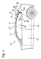
- FIG. 1 shown motor vehicle 10 has a body 11 and doors 12.
- the doors 12 are each provided with a movable window pane 14.
- the rearward in the direction of travel of the motor vehicle 10 door 12 is also provided with a fixed, often referred to as a triangular window pane 15.
- a sealing profile 20 is used.
- the sealing profile extruded from an elastomeric material has a first sealing section 21 which extends in the longitudinal direction of the sealing profile 20 and has an outer sealing lip 22 and an inner sealing lip 23 viewed from the outside of the motor vehicle 10 ,
- the sealing lips 22, 23 extend in the longitudinal direction of the sealing portion 21 and the sealing profile 20 and are arranged in a transverse to the longitudinal direction orthogonal transverse direction at a distance a from each other.
- Each of a free end 24 and the free end 24 remote from the foot 25 having sealing lips 22, 23 project from an outer surface 34 of the sealing portion 21, which extends in the transverse direction.
- the inner sealing lip 23 encloses an acute angle ⁇ with the outer surface 34.
- Both the outer sealing lip 22 and the inner sealing lip 23 are on the in Closed state of the door 12 on the body 11 adjacent the inside provided with a friction-reducing flocking 33, which prevents adhesion of the sealing lips 22, 23 on the body 11.
- the sealing profile 20 is further provided with a second sealing portion 31, which serves to seal the windows 14, 15.
- the sealing portion 31 is configured in the region of the movable window pane 14 as a window guide and has a channel 35 which receives the upper edge of the window pane 14 in the closed state.
- sealing lips 32 are arranged, which rest in the closed state of the window pane 14 at this and are provided on the voltage applied to the window pane 14 side with a friction-reducing flock 33.
- the sealing portion 31 is configured in the region of the fixed window pane 15 as a disk enclosure, through which the window pane 15 is sealingly enclosed.
- the sealing profile 20 between the first sealing portion 21 and the second sealing portion 31 has a fastening portion 26 which serves to fasten the sealing profile 20 to a flange 13 of the door 12.
- the attachment portion 26 has for this purpose a channel-shaped recess 28 which is attachable to the flange 13.
- holding lips 29 are arranged in the recess 28.
- the attachment portion 26 is amiert by a reinforcing beam 30 which is U-shaped in cross section.
- the reinforcing beam 30 may be made of, for example, a metal stamping tape or a bent wire helix tape.
- the sealing profile 20 is curved in the longitudinal direction.
- the curvature K follows the contour of the door 12 respectively the body 11 and is particularly strong in the transition from the C-pillar of the motor vehicle 10 to the car body.
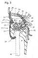
- the sealing section 21 is provided with an additional section 27 which is arranged on the foot 25 of the inner sealing lip 23.
- Fig. 3 is to be recognized, for example, by variable extrusion or by injection molding on the sealing lip 23 produced additional portion 27 in cross-section substantially wedge-shaped and supported in this way the cross-sectionally substantially pin-shaped and relative to the outer surface 34 inclined sealing lip 23 from.
- the sealing profile 20 described above is characterized in that an undesired deformation of the sealing lip 23 in the region of the strong curvature K during bending of the sealing profile 20 is avoided. This is mainly due to the additional section 27, which supports the sealing lip 23 locally.
- the additional portion 27 prevents collapse of the sealing portion 21 in the region of the curvature K and in this way allows the sealing profile 20 to be manufactured by extrusion in the region of the curvature K.
- the sealing profile 20 therefore takes into account a simple and cost-effective production.
Abstract
Description
Die vorliegende Erfindung betrifft ein Dichtungsprofil, das insbesondere zum Abdichten einer Tür gegenüber der Karosserie eines Kraftfahrzeugs dient. Das Dichtungsprofil ist mit wenigstens einem Dichtungsabschnitt versehen, der wenigstens eine Dichtlippe aufweist und sich in einer Längsrichtung erstreckt. Das Dichtungsprofil ist ferner mit einem Befestigungsabschnitt versehen, der an einem Bauteil, zum Beispiel einem Flansch der Tür eines Kraftfahrzeugs, befestigbar ist. Der Dichtungsabschnitt ist aus einem elastisch verformbaren Werkstoff gefertigt und in der Längsrichtung gekrümmt. Die Dichtlippe weist ein freies Ende und einen dem freien Ende abgewandten Fuß auf.The present invention relates to a sealing profile, which is used in particular for sealing a door relative to the body of a motor vehicle. The sealing profile is provided with at least one sealing portion having at least one sealing lip and extending in a longitudinal direction. The sealing profile is further provided with a fixing portion, which is fastened to a component, for example a flange of the door of a motor vehicle. The sealing portion is made of an elastically deformable material and curved in the longitudinal direction. The sealing lip has a free end and a foot facing away from the free end.
Ein Dichtungsprofil, das einen mit zwei Dichtlippen versehenen Dichtungsabschnitt umfasst, wird in der
Weiterhin ist aus der
Überdies geht aus der
Als Nachteil der bekannten Dichtungsprofile hat sich herausgestellt, dass, wenn das Dichtungsprofil, vor allem der Dichtungsabschnitt, in der Längsrichtung stark gekrümmt ist, wie zum Beispiel ein häufig als Stilelement zu findender geknickter Übergang von der C-Säule eines Kraftfahrzeugs zum Wagenkörper, die Dichtlippe aufgrund der durch den gekrümmten Verlauf auftretenden Zugspannungen eine Verformung erfährt, die zum einen das optische Erscheinungsbild und zum anderen die Dichtwirkung beeinträchtigt.As a disadvantage of the known sealing profiles has been found that when the sealing profile, especially the sealing portion is strongly curved in the longitudinal direction, such as a frequently as a style element to findender kinked transition from the C-pillar of a motor vehicle to the car body, the sealing lip undergoes a deformation due to the tensile stresses occurring due to the curved course, which affects on the one hand the visual appearance and on the other hand, the sealing effect.
Der Erfindung liegt die Aufgabe zugrunde, ein Dichtungsprofil der eingangs genannten Art dahingehend weiterzubilden, dass sich eine unerwünschte Verformung der Dichtlippe in Bereichen starker Krümmung vermeiden lässt.The invention has the object of developing a sealing profile of the type mentioned in that an undesirable deformation of the sealing lip in areas of strong curvature can be avoided.
Diese Aufgabe wird durch ein Dichtungsprofil mit den Merkmalen des Anspruchs 1 gelöst. Bevorzugte Ausgestaltungen eines solchen Dichtungsprofils werden in den Ansprüchen 2 bis 16 definiert.This object is achieved by a sealing profile having the features of claim 1. Preferred embodiments of such a sealing profile are defined in claims 2 to 16.
Das erfindungsgemäße Dichtungsprofil zeichnet sich durch einen Zusatzabschnitt aus, der im Bereich einer vorgegebenen Krümmung des Dichtungsabschnitts an dem Fuß der Dichtlippe angeordnet ist. Die lokale Anordnung des Zusatzabschnittes in Bereichen starker Krümmung führt zu einer Stabilisierung der im Querschnitt häufig stiftförmigen Dichtlippe, die sicherstellt, dass die Dichtlippe keine übermäßige Verformung erfährt, sondern in der geforderten Lage bleibt. Ein in ästhetischer Hinsicht ansprechendes optisches Erscheinungsbild und eine zuverlässige Dichtwirkung sind somit sichergestellt. Darüber hinaus ist eine mit einem hohen Aufwand verbundene Nachbehandlung des Dichtungsprofils, wie sie im Stand der Technik üblich ist, indem durch eine übermäßige Verformung der Dichtlippe eingefallene Konturen des Dichtungsabschnitts entfernt, neu anvulkanisiert und gegebenenfalls nachbeflockt oder nachlackiert werden, entbehrlich.The sealing profile according to the invention is characterized by an additional portion which is arranged in the region of a predetermined curvature of the sealing portion at the foot of the sealing lip. The local arrangement of the additional portion in areas of high curvature leads to a stabilization of the cross-sectionally often pin-shaped sealing lip, which ensures that the sealing lip undergoes no excessive deformation, but remains in the required position. An aesthetically pleasing visual appearance and a reliable sealing effect are thus ensured. In addition, associated with a high cost aftertreatment of the sealing profile, as is customary in the art by removed by excessive deformation of the sealing lip sunken contours of the sealing portion, re-vulcanized and optionally post-flocked or repainted unnecessary.
In Hinsicht auf eine praxisgerechte Fertigung ist es zweckmäßig, den Dichtungsabschnitt und/oder den Befestigungsabschnitt aus einem elastomeren Werkstoff, vorzugsweise einem thermoplastischen Elastomer (TPE) oder Ethylen-Propylen-Dien-Kautschuk (EPDM), zu extrudieren. In diesem Zusammenhang hat es sich als vorteilhaft erwiesen, den Zusatzabschnitt durch variable Extrusion, wie sie zum Beispiel aus der
In einer bevorzugten Ausgestaltung des erfindungsgemäßen Dichtungsprofils weist der Dichtungsabschnitt eine Außenfläche auf, die sich in einer Querrichtung des Dichtungsabschnitts erstreckt. Die Dichtlippe ist in einem vorzugsweise spitzen Winkel zu der Außenfläche angeordnet. In diesem Fall hat es sich als vorteilhaft erwiesen, wenn der Zusatzabschnitt im Querschnitt annähernd keilförmig ist, um auf diese Weise die geneigte Dichtlippe abzustützen.In a preferred embodiment of the sealing profile according to the invention, the sealing portion has an outer surface which extends in a transverse direction of the sealing portion. The sealing lip is arranged at a preferably acute angle to the outer surface. In this case, it has proved to be advantageous if the additional portion is approximately wedge-shaped in cross section, in order to support the inclined sealing lip in this way.
Zweckmäßigerweise ist die Dichtlippe mit einer reibungsvermindernden Beschichtung oder Beflockung versehen, die ein Anhaften der Dichtlippe an beispielsweise der Karosserie eines Kraftfahrzeugs verhindert. Die reibungsvermindernde Beschichtung oder Beflockung wird vorteilhafterweise ausschließlich auf der Seite Dichtlippe aufgebracht, die an beispielsweise der Karosserie des Kraftfahrzeugs anliegt. Um ein einfaches Beschichten oder Beflocken der Dichtlippe zu gewährleisten, befindet sich der Zusatzabschnitt in diesem Fall bevorzugt auf der der Beschichtung oder Beflockung abgewandten Seite der Dichtlippe.Conveniently, the sealing lip is provided with a friction-reducing coating or flocking, which prevents adhesion of the sealing lip, for example, the body of a motor vehicle. The friction-reducing coating or flocking is advantageously applied exclusively on the side of the sealing lip, which bears against, for example, the body of the motor vehicle. In order to ensure a simple coating or flocking of the sealing lip, the additional section is in this case preferably on the side facing away from the coating or flocking side of the sealing lip.
In einer bevorzugten Ausgestaltung des erfindungsgemäßen Dichtungsprofils weist der Dichtungsabschnitt eine, von der Außenseite eines Kraftfahrzeugs betrachtet, äußere Dichtlippe und eine innere Dichtlippe auf, die sich in Längsrichtung des Dichtungsabschnitts erstrecken und in der Querrichtung des Dichtungsabschnitts in einem Abstand voneinander angeordnet sind. In diesem Zusammenhang hat es sich als vorteilhaft erwiesen, wenn der Zusatzabschnitt ausschließlich an dem Fuß der inneren Dichtlippe angeordnet ist. Es hat sich herausgestellt, dass es ausreichend ist, den Zusatzabschnitt an der inneren Dichtlippe anzuordnen, die in der Regel stärker geneigt ist als die äußere Dichtlippe und dadurch einer höheren Beanspruchung beim Biegen des Dichtungsabschnitts unterliegt.In a preferred embodiment of the sealing profile according to the invention, the sealing portion has, viewed from the outside of a motor vehicle, outer sealing lip and an inner sealing lip, which extend in the longitudinal direction of the sealing portion and are arranged in the transverse direction of the sealing portion at a distance from each other. In this context, it has proved to be advantageous if the additional section is arranged exclusively on the foot of the inner sealing lip. It has been found that it is sufficient, the additional section to be arranged on the inner sealing lip, which is usually more inclined than the outer sealing lip and thereby subject to a higher stress during bending of the sealing portion.
Bevorzugt weist das Dichtungsprofil einen ersten Dichtungsabschnitt, der zum Abdichten einer Tür gegenüber der Karosserie eines Kraftfahrzeugs dient, und einen zweiten Dichtungsabschnitt, der zum Abdichten wenigstens einer Fensterscheibe dient, auf. Der erste Dichtungsabschnitt und der zweite Dichtungsabschnitt werden zweckmäßigerweise gemeinsam extrudiert. Der zweite Dichtungsabschnitt kann als Fensterführung ausgestaltet sein, um eine bewegbare Fensterscheibe abzudichten und zu führen. Alternativ kann der zweite Dichtungsabschnitt auch als Scheibeneinfassung für eine feststehende Fensterscheibe ausgestaltet sein.The sealing profile preferably has a first sealing section, which serves to seal a door with respect to the body of a motor vehicle, and a second sealing section, which serves to seal at least one window pane. The first sealing portion and the second sealing portion are expediently extruded together. The second sealing portion may be configured as a window guide to seal and guide a movable window pane. Alternatively, the second sealing portion may also be configured as a window surround for a fixed window pane.
Um eine praxisgerechte Befestigung des Dichtungsprofils sicherzustellen, ist bevorzugt der Befestigungsabschnitt mit einer kanalförmigen Aussparung versehen, die auf beispielsweise einen Flansch der Tür eines Kraftfahrzeugs aufsteckbar ist. Alternativ kann der Befestigungsabschnitt in an sich bekannter Weise an den Flansch geklebt werden, zum Beispiel mittels eines Klebebands.In order to ensure a practice-oriented fastening of the sealing profile, the fastening section is preferably provided with a channel-shaped recess which can be plugged onto, for example, a flange of the door of a motor vehicle. Alternatively, the attachment portion may be glued to the flange in a manner known per se, for example by means of an adhesive tape.
Um einen hohen Kraftschluss sicherzustellen, ist der Befestigungsabschnitt vorteilhafterweise mit Haltelippen versehen, die in der Aussparung angeordnet sind. In diesem Zusammenhang hat es sich ferner als vorteilhaft erwiesen, den Befestigungsabschnitt durch einen Verstärkungsträger zu armieren. Der Verstärkungsträger ist zweckmäßigerweise im Querschnitt U-förmig ausgestaltet und aus einem metallischen Werkstoff gefertigt. Um eine ausreichende Verformungsfähigkeit des Verstärkungsträgers zu gewährleisten, kann dieser mit einer Vielzahl an beispielsweise gestanzten Öffnungen versehen sein.
Einzelheiten und weitere Vorteile des erfindungsgemäßen Dichtungsprofils ergeben sich aus der nachfolgenden Beschreibung eines bevorzugten Ausführungsbeispiels. In den das Ausführungsbeispiel lediglich schematisch darstellenden Zeichnungen veranschaulichen im Einzelnen:
- Fig. 1
- eine Seitenansicht eines Kraftfahrzeugs;
- Fig. 2
- einen Schnitt durch das erfindungsgemäße Dichtungsprofil gemäß der Linie ll-ll in
Fig. 1 und - Fig. 3
- einen Schnitt durch das erfindungsgemäße Dichtungsprofil gemäß der Linie III-III in
Fig. 1 .
Details and further advantages of the sealing profile according to the invention will become apparent from the following description of a preferred embodiment. In the drawings, which only schematically illustrate the exemplary embodiment, illustrate in detail:
- Fig. 1
- a side view of a motor vehicle;
- Fig. 2
- a section through the sealing profile according to the invention according to the line ll-ll in
Fig. 1 and - Fig. 3
- a section through the sealing profile according to the invention according to the line III-III in
Fig. 1 ,
Das in
Das aus einem elastomeren Werkstoff, wie zum Beispiel TPE oder EPDM, extrudierte Dichtungsprofil weist einen ersten Dichtungsabschnitt 21 auf, der sich in Längsrichtung des Dichtungsprofils 20 erstreckt und eine, von der Außenseite des Kraftfahrzeugs 10 betrachtet, äußere Dichtlippe 22 und eine innere Dichtlippe 23 aufweist. Die Dichtlippen 22, 23 erstrecken sich in Längsrichtung des Dichtungsabschnitts 21 beziehungsweise des Dichtungsprofils 20 und sind in einer zu der Längsrichtung orthogonalen Querrichtung in einem Abstand a voneinander angeordnet. Die jeweils ein freies Ende 24 und einen dem freien Ende 24 abgewandten Fuß 25 aufweisenden Dichtlippen 22, 23 ragen aus einer Außenfläche 34 des Dichtungsabschnitts 21 heraus, die sich in der Querrichtung erstreckt. Die innere Dichtlippe 23 schließt mit der Außenfläche 34 einen spitzen Winkel α ein. Die äußere Dichtlippe 22 hingegen schließt mit der Außenfläche 34 einen Winkel β ein, der im unbelasteten Zustand des Dichtungsabschnitts 21 annähernd 90° beträgt. Sowohl die äußere Dichtlippe 22 als auch die innere Dichtlippe 23 sind auf der im geschlossenen Zustand der Tür 12 an der Karosserie 11 anliegenden Innenseite mit einer reibungsvermindernden Beflockung 33 versehen, die ein Anhaften der Dichtlippen 22, 23 an der Karosserie 11 verhindert.The sealing profile extruded from an elastomeric material, such as TPE or EPDM, has a
Wie die
Weiterhin geben die
Wie
Das zuvor beschriebene Dichtungsprofil 20 zeichnet sich dadurch aus, dass eine unerwünschte Verformung der Dichtlippe 23 im Bereich der starken Krümmung K beim Biegen des Dichtungsprofils 20 vermieden wird. Dies ist vor allem auf den Zusatzabschnitt 27 zurückzuführen, der die Dichtlippe 23 lokal abstützt. Der Zusatzabschnitt 27 verhindert ein Einfallen des Dichtungsabschnitts 21 im Bereich der Krümmung K und ermöglicht auf diese Weise, das Dichtungsprofil 20 auch im Bereich der Krümmung K durch Extrusion zu fertigen. Im Unterschied zum Stand der Technik ist es somit nicht erforderlich, das Dichtungsprofil 20 im Bereich der Krümmung K mit einem spritzgegossenen Formteil zu versehen, das an den gekrümmten Verlauf des Dichtungsabschnitts 21 im Bereich der Krümmung K angepasst ist. Nicht zuletzt trägt das Dichtungsprofil 20 daher einer einfachen und kostengünstigen Fertigung Rechnung.The sealing
- 1010
- Kraftfahrzeugmotor vehicle
- 1111
- Karosseriebody
- 1212
- Türdoor
- 1313
- Flanschflange
- 1414
- bewegbare Fensterscheibemovable window pane
- 1515
- feststehende Fensterscheibefixed window pane
- 2020
- Dichtungsprofilweatherstrip
- 2121
- erster Dichtungsabschnittfirst sealing section
- 2222
- äußere Dichtlippeouter sealing lip
- 2323
- innere Dichtlippeinner sealing lip
- 2424
- freies Endefree end
- 2525
- Fußfoot
- 2626
- Befestigungsabschnittattachment section
- 2727
- Zusatzabschnittadditional section
- 2828
- Aussparungrecess
- 2929
- Haltelipperetaining lip
- 3030
- Verstärkungsträgerreinforcing support
- 3131
- zweiter Dichtungsabschnittsecond sealing section
- 3232
- Dichtlippesealing lip
- 3333
- Beflockungflocking
- 3434
- Außenflächeouter surface
- 3535
- Kanalchannel
- aa
- Abstanddistance
- αα
- Winkelangle
- ββ
- Winkelangle
- KK
- Krümmungcurvature
Claims (16)
einem Dichtungsabschnitt (21, 31), der wenigstens eine Dichtlippe (22, 23, 32) aufweist und sich in einer Längsrichtung erstreckt, und
einem Befestigungsabschnitt (26), der an einem Bauteil (13) befestigbar ist,
wobei der Dichtungsabschnitt (21, 31) aus einem elastisch verformbaren Werkstoff gefertigt und in der Längsrichtung gekrümmt ist und
wobei die Dichtlippe (22, 23) ein freies Ende (24) und einen dem freien Ende (24) abgewandten Fuß (25) aufweist,
gekennzeichnet durch einen Zusatzabschnitt (27), der im Bereich einer vorgegebenen Krümmung (K) des Dichtungsabschnitts (21) an dem Fuß (25) der Dichtlippe (22, 23) angeordnet ist.Sealing profile, in particular for sealing a door (12) relative to the body (11) of a motor vehicle (10), with
a sealing portion (21, 31) having at least one sealing lip (22, 23, 32) and extending in a longitudinal direction, and
a fixing portion (26) attachable to a component (13),
wherein the sealing portion (21, 31) is made of an elastically deformable material and curved in the longitudinal direction, and
the sealing lip (22, 23) having a free end (24) and a foot (25) facing away from the free end (24),
characterized by an additional portion (27) which is arranged in the region of a predetermined curvature (K) of the sealing portion (21) on the foot (25) of the sealing lip (22, 23).
Priority Applications (1)
| Application Number | Priority Date | Filing Date | Title |
|---|---|---|---|
| PL07118682T PL1935694T3 (en) | 2006-12-20 | 2007-10-17 | Sealing profile, in particular for sealing between a door and the bodywork of a motor vehicle |
Applications Claiming Priority (1)
| Application Number | Priority Date | Filing Date | Title |
|---|---|---|---|
| DE102006060390A DE102006060390B3 (en) | 2006-12-20 | 2006-12-20 | Door sealing profile for e.g. car, has sealing section with sealing lip extending in longitudinal direction, and auxiliary section provided and arranged in area of curvature at base of sealing lip |
Publications (3)
| Publication Number | Publication Date |
|---|---|
| EP1935694A1 true EP1935694A1 (en) | 2008-06-25 |
| EP1935694B1 EP1935694B1 (en) | 2009-09-30 |
| EP1935694B8 EP1935694B8 (en) | 2009-12-09 |
Family
ID=38885272
Family Applications (1)
| Application Number | Title | Priority Date | Filing Date |
|---|---|---|---|
| EP07118682A Not-in-force EP1935694B8 (en) | 2006-12-20 | 2007-10-17 | Sealing profile, in particular for sealing between a door and the bodywork of a motor vehicle |
Country Status (5)
| Country | Link |
|---|---|
| EP (1) | EP1935694B8 (en) |
| AT (1) | ATE444195T1 (en) |
| DE (2) | DE102006060390B3 (en) |
| ES (1) | ES2332153T3 (en) |
| PL (1) | PL1935694T3 (en) |
Cited By (3)
| Publication number | Priority date | Publication date | Assignee | Title |
|---|---|---|---|---|
| DE102016007480A1 (en) | 2016-06-18 | 2017-02-09 | Daimler Ag | DC converter for a vehicle |
| CN110914086A (en) * | 2017-05-11 | 2020-03-24 | 亨尼格斯汽车密封系统北美公司 | Seal assembly |
| CN113613924A (en) * | 2019-04-05 | 2021-11-05 | 奥迪股份公司 | Sealing element with covering section, vehicle door and vehicle with sealing element, and method for producing sealing element |
Families Citing this family (8)
| Publication number | Priority date | Publication date | Assignee | Title |
|---|---|---|---|---|
| FR2928615A1 (en) * | 2008-03-12 | 2009-09-18 | Peugeot Citroen Automobiles Sa | VEHICLE ASSEMBLIES, IN PARTICULAR A MOTOR VEHICLE HAVING A FRAME STRUCTURE AND A SEALING PROFILE |
| DE102008027877A1 (en) * | 2008-06-11 | 2009-12-17 | Bayerische Motoren Werke Aktiengesellschaft | Seal for a door of a motor vehicle |
| DE102008055942B4 (en) | 2008-11-05 | 2012-03-01 | Metzeler Automotive Profile Systems Gmbh | Method for producing a sealing profile for a motor vehicle and such a sealing profile |
| US9027284B2 (en) | 2012-05-15 | 2015-05-12 | Henniges Automotive Sealing Systems North America, Inc. | Sealing member |
| DE102013101896A1 (en) | 2013-02-26 | 2014-08-28 | Bayerische Motoren Werke Aktiengesellschaft | weatherstrip |
| EP2803518B9 (en) * | 2013-05-15 | 2017-12-13 | Henniges Automotive Sealing Systems North America, Inc. | Sealing member |
| WO2015120395A1 (en) | 2014-02-07 | 2015-08-13 | Henniges Automotive Sealing Systems North America, Inc. | Method of manufacturing a vehicle sealing assembly |
| EP2944492B1 (en) * | 2014-05-14 | 2019-09-11 | Volvo Car Corporation | A glass run seal for a movable pane in a vehicle window aperture. |
Citations (13)
| Publication number | Priority date | Publication date | Assignee | Title |
|---|---|---|---|---|
| US4374880A (en) | 1979-11-13 | 1983-02-22 | Etablissements Mesnel | Sealing strip |
| JPH0238323U (en) | 1988-09-08 | 1990-03-14 | ||
| US5296067A (en) | 1990-11-20 | 1994-03-22 | Etablissements Mesnel S.A. | Process for production of a seal for the frame of an aperture of the body of an automobile |
| JPH10181351A (en) | 1996-12-24 | 1998-07-07 | Toyoda Gosei Co Ltd | Automobile weather strip |
| WO2000073097A1 (en) * | 1999-05-27 | 2000-12-07 | Schlegel Corporation | Glass run surround cap |
| US20010001916A1 (en) | 1999-11-30 | 2001-05-31 | Masahiro Nozaki | Glass run of an automobile |
| JP2002127756A (en) | 2000-08-15 | 2002-05-08 | Kinugawa Rubber Ind Co Ltd | Door weather strip |
| GB2393751A (en) * | 2002-10-02 | 2004-04-07 | Gencorp Property Inc | Joint in weather strip using both moulding and heat activated material |
| GB2393752A (en) | 2002-10-02 | 2004-04-07 | Gencorp Property Inc | Extruded sealing strip, with part of the section replaced by moulded material over some of the length |
| WO2004050408A1 (en) * | 2002-12-04 | 2004-06-17 | Gdx North America Inc. | Window sealing and guiding arrangements |
| EP1500542A1 (en) * | 2003-07-25 | 2005-01-26 | Metzeler Automotive Profile Systems GmbH | Seal arrangement, particularly for fixed vehicle window panes |
| EP1577137A1 (en) | 2004-02-26 | 2005-09-21 | Metzeler Automotive Profile Systems Transieres | Profile made of at least an elastomer or a plastomer, particulary designed for the equipment of an opening or framing an opening, and process for its manufacture |
| US20060254149A1 (en) * | 2005-04-22 | 2006-11-16 | Tokai Kogyo Co., Ltd. | Long trim member for vehicle and attaching method of the same |
Family Cites Families (2)
| Publication number | Priority date | Publication date | Assignee | Title |
|---|---|---|---|---|
| JP3814946B2 (en) * | 1997-05-27 | 2006-08-30 | 豊田合成株式会社 | Method for forming corner part of door glass run for automobile |
| DE10159251C1 (en) * | 2001-12-03 | 2003-04-30 | Metzeler Automotive Profile | Housing frame for a stationary window pane of a motor vehicle door comprises an extruded sealing profile made of an elastomer material, and a pane holder molded on the sealing profile |
-
2006
- 2006-12-20 DE DE102006060390A patent/DE102006060390B3/en not_active Expired - Fee Related
-
2007
- 2007-10-17 AT AT07118682T patent/ATE444195T1/en not_active IP Right Cessation
- 2007-10-17 ES ES07118682T patent/ES2332153T3/en active Active
- 2007-10-17 PL PL07118682T patent/PL1935694T3/en unknown
- 2007-10-17 DE DE502007001620T patent/DE502007001620D1/en active Active
- 2007-10-17 EP EP07118682A patent/EP1935694B8/en not_active Not-in-force
Patent Citations (13)
| Publication number | Priority date | Publication date | Assignee | Title |
|---|---|---|---|---|
| US4374880A (en) | 1979-11-13 | 1983-02-22 | Etablissements Mesnel | Sealing strip |
| JPH0238323U (en) | 1988-09-08 | 1990-03-14 | ||
| US5296067A (en) | 1990-11-20 | 1994-03-22 | Etablissements Mesnel S.A. | Process for production of a seal for the frame of an aperture of the body of an automobile |
| JPH10181351A (en) | 1996-12-24 | 1998-07-07 | Toyoda Gosei Co Ltd | Automobile weather strip |
| WO2000073097A1 (en) * | 1999-05-27 | 2000-12-07 | Schlegel Corporation | Glass run surround cap |
| US20010001916A1 (en) | 1999-11-30 | 2001-05-31 | Masahiro Nozaki | Glass run of an automobile |
| JP2002127756A (en) | 2000-08-15 | 2002-05-08 | Kinugawa Rubber Ind Co Ltd | Door weather strip |
| GB2393751A (en) * | 2002-10-02 | 2004-04-07 | Gencorp Property Inc | Joint in weather strip using both moulding and heat activated material |
| GB2393752A (en) | 2002-10-02 | 2004-04-07 | Gencorp Property Inc | Extruded sealing strip, with part of the section replaced by moulded material over some of the length |
| WO2004050408A1 (en) * | 2002-12-04 | 2004-06-17 | Gdx North America Inc. | Window sealing and guiding arrangements |
| EP1500542A1 (en) * | 2003-07-25 | 2005-01-26 | Metzeler Automotive Profile Systems GmbH | Seal arrangement, particularly for fixed vehicle window panes |
| EP1577137A1 (en) | 2004-02-26 | 2005-09-21 | Metzeler Automotive Profile Systems Transieres | Profile made of at least an elastomer or a plastomer, particulary designed for the equipment of an opening or framing an opening, and process for its manufacture |
| US20060254149A1 (en) * | 2005-04-22 | 2006-11-16 | Tokai Kogyo Co., Ltd. | Long trim member for vehicle and attaching method of the same |
Cited By (5)
| Publication number | Priority date | Publication date | Assignee | Title |
|---|---|---|---|---|
| DE102016007480A1 (en) | 2016-06-18 | 2017-02-09 | Daimler Ag | DC converter for a vehicle |
| CN110914086A (en) * | 2017-05-11 | 2020-03-24 | 亨尼格斯汽车密封系统北美公司 | Seal assembly |
| CN110914086B (en) * | 2017-05-11 | 2023-03-10 | 亨尼格斯汽车密封系统北美公司 | Seal assembly |
| US11691490B2 (en) | 2017-05-11 | 2023-07-04 | Henniges Automotive Sealing Systems North America, Inc. | Seal assembly |
| CN113613924A (en) * | 2019-04-05 | 2021-11-05 | 奥迪股份公司 | Sealing element with covering section, vehicle door and vehicle with sealing element, and method for producing sealing element |
Also Published As
| Publication number | Publication date |
|---|---|
| EP1935694B8 (en) | 2009-12-09 |
| DE502007001620D1 (en) | 2009-11-12 |
| ATE444195T1 (en) | 2009-10-15 |
| PL1935694T3 (en) | 2010-05-31 |
| EP1935694B1 (en) | 2009-09-30 |
| ES2332153T3 (en) | 2010-01-27 |
| DE102006060390B3 (en) | 2008-02-07 |
Similar Documents
| Publication | Publication Date | Title |
|---|---|---|
| EP1935694B1 (en) | Sealing profile, in particular for sealing between a door and the bodywork of a motor vehicle | |
| DE60018608T2 (en) | ADDING A CAR WASHER TO A CONNECTION ELEMENT | |
| EP2814681B1 (en) | Sealing assembly for vehicle windows, corresponding manufacturing method and application | |
| DE102018221388A1 (en) | Motor vehicle door sealing structure | |
| DE202008013133U1 (en) | Glazing Sealant | |
| EP1131220B2 (en) | Window sealing strip for a convertible | |
| EP2117865A1 (en) | Sealing profile and sealing system including the same | |
| DE102016213605A1 (en) | Construction for fixing a molding on a car door | |
| DE102019213352A1 (en) | MOTOR VEHICLE DOOR SEALING STRUCTURE | |
| EP1316456B1 (en) | Holding frame with sealing profile for a fixed window | |
| DE102008010547B3 (en) | Cover strip for motor vehicle, has extruded hollow space section, which has hollow space, where extruded fixing section stretches in longitudinal direction and is connected with hollow space section | |
| EP1131218B1 (en) | Window seal for a convertible | |
| DE102021202561A1 (en) | SEALING ELEMENT FOR A VEHICLE DOOR | |
| DE102005028738B3 (en) | Window pane sealing arrangement for motor vehicle, has formed part comprising base body and end section with groove that is formed by two fingers, where fingers are disconnected in longitudinal direction of groove by recess | |
| DE102005012685A1 (en) | Method of making continuous sealing profile for automobile use, includes main section extruded in one material and additional integral section extruded in second material | |
| DE102007059411B4 (en) | Seal for sealing the window pane of a motor vehicle, reinforcement support for such a seal and method for producing the seal | |
| DE202008014739U1 (en) | Sealing arrangement for the window slot of a vehicle door | |
| EP2129506B1 (en) | Method for the production of a sealing assembly, in particular for a motor vehicle, having a sealing element and a support, and such a sealing assembly | |
| DE102008006545B4 (en) | Method for producing a seal, in particular for a motor vehicle and such a seal | |
| EP2222491B1 (en) | Method for producing a sealing profile for a motor vehicle and such a sealing profile | |
| DE102009049455B4 (en) | Sealing profile and method for producing a sealing profile | |
| DE102005050962A1 (en) | Weatherstrip for use in motor vehicle, has deformation control elements, formed within ductile weatherstrip base, which limits deformation of base upon application of force | |
| DE10259842A1 (en) | Coextruded seal unit, in particular, for window panes of motor vehicles comprises a seal body with a bending section consisting of a material with a higher elasticity than the rest of the seal body | |
| DE102004007887B4 (en) | Damping strip and frame, in particular for a sunroof roof, method for producing a damping strip or a frame, in particular for a sunroof headliner | |
| DE3427346A1 (en) | METHOD FOR PRODUCING SEALING AND / OR CLAMP PROFILING STRIPS |
Legal Events
| Date | Code | Title | Description |
|---|---|---|---|
| PUAI | Public reference made under article 153(3) epc to a published international application that has entered the european phase |
Free format text: ORIGINAL CODE: 0009012 |
|
| AK | Designated contracting states |
Kind code of ref document: A1 Designated state(s): AT BE BG CH CY CZ DE DK EE ES FI FR GB GR HU IE IS IT LI LT LU LV MC MT NL PL PT RO SE SI SK TR |
|
| AX | Request for extension of the european patent |
Extension state: AL BA HR MK RS |
|
| RTI1 | Title (correction) |
Free format text: SEALING PROFILE, IN PARTICULAR FOR SEALING BETWEEN A DOOR AND THE BODYWORK OF A MOTOR VEHICLE |
|
| 17P | Request for examination filed |
Effective date: 20081010 |
|
| 17Q | First examination report despatched |
Effective date: 20081114 |
|
| AKX | Designation fees paid |
Designated state(s): AT BE BG CH CY CZ DE DK EE ES FI FR GB GR HU IE IS IT LI LT LU LV MC MT NL PL PT RO SE SI SK TR |
|
| GRAP | Despatch of communication of intention to grant a patent |
Free format text: ORIGINAL CODE: EPIDOSNIGR1 |
|
| GRAS | Grant fee paid |
Free format text: ORIGINAL CODE: EPIDOSNIGR3 |
|
| GRAA | (expected) grant |
Free format text: ORIGINAL CODE: 0009210 |
|
| TPAC | Observations filed by third parties |
Free format text: ORIGINAL CODE: EPIDOSNTIPA |
|
| AK | Designated contracting states |
Kind code of ref document: B1 Designated state(s): AT BE BG CH CY CZ DE DK EE ES FI FR GB GR HU IE IS IT LI LT LU LV MC MT NL PL PT RO SE SI SK TR |
|
| REG | Reference to a national code |
Ref country code: GB Ref legal event code: FG4D Free format text: NOT ENGLISH Ref country code: CH Ref legal event code: EP |
|
| REG | Reference to a national code |
Ref country code: IE Ref legal event code: FG4D |
|
| RAP2 | Party data changed (patent owner data changed or rights of a patent transferred) |
Owner name: METZELER AUTOMOTIVE PROFILE SYSTEMS GMBH |
|
| REF | Corresponds to: |
Ref document number: 502007001620 Country of ref document: DE Date of ref document: 20091112 Kind code of ref document: P |
|
| REG | Reference to a national code |
Ref country code: RO Ref legal event code: EPE |
|
| NLT2 | Nl: modifications (of names), taken from the european patent patent bulletin |
Owner name: METZELER AUTOMOTIVE PROFILE SYSTEMS GMBH Effective date: 20091111 |
|
| REG | Reference to a national code |
Ref country code: ES Ref legal event code: FG2A Ref document number: 2332153 Country of ref document: ES Kind code of ref document: T3 |
|
| PG25 | Lapsed in a contracting state [announced via postgrant information from national office to epo] |
Ref country code: LT Free format text: LAPSE BECAUSE OF FAILURE TO SUBMIT A TRANSLATION OF THE DESCRIPTION OR TO PAY THE FEE WITHIN THE PRESCRIBED TIME-LIMIT Effective date: 20090930 Ref country code: FI Free format text: LAPSE BECAUSE OF FAILURE TO SUBMIT A TRANSLATION OF THE DESCRIPTION OR TO PAY THE FEE WITHIN THE PRESCRIBED TIME-LIMIT Effective date: 20090930 Ref country code: SE Free format text: LAPSE BECAUSE OF FAILURE TO SUBMIT A TRANSLATION OF THE DESCRIPTION OR TO PAY THE FEE WITHIN THE PRESCRIBED TIME-LIMIT Effective date: 20090930 |
|
| LTIE | Lt: invalidation of european patent or patent extension |
Effective date: 20090930 |
|
| PG25 | Lapsed in a contracting state [announced via postgrant information from national office to epo] |
Ref country code: LV Free format text: LAPSE BECAUSE OF FAILURE TO SUBMIT A TRANSLATION OF THE DESCRIPTION OR TO PAY THE FEE WITHIN THE PRESCRIBED TIME-LIMIT Effective date: 20090930 Ref country code: SI Free format text: LAPSE BECAUSE OF FAILURE TO SUBMIT A TRANSLATION OF THE DESCRIPTION OR TO PAY THE FEE WITHIN THE PRESCRIBED TIME-LIMIT Effective date: 20090930 |
|
| NLV1 | Nl: lapsed or annulled due to failure to fulfill the requirements of art. 29p and 29m of the patents act | ||
| REG | Reference to a national code |
Ref country code: SK Ref legal event code: T3 Ref document number: E 6588 Country of ref document: SK |
|
| BERE | Be: lapsed |
Owner name: METZELER AUTOMOTIVE PROFILES SYSTEMS G.M.B.H. Effective date: 20091031 |
|
| PG25 | Lapsed in a contracting state [announced via postgrant information from national office to epo] |
Ref country code: IS Free format text: LAPSE BECAUSE OF FAILURE TO SUBMIT A TRANSLATION OF THE DESCRIPTION OR TO PAY THE FEE WITHIN THE PRESCRIBED TIME-LIMIT Effective date: 20100130 Ref country code: PT Free format text: LAPSE BECAUSE OF FAILURE TO SUBMIT A TRANSLATION OF THE DESCRIPTION OR TO PAY THE FEE WITHIN THE PRESCRIBED TIME-LIMIT Effective date: 20100201 Ref country code: EE Free format text: LAPSE BECAUSE OF FAILURE TO SUBMIT A TRANSLATION OF THE DESCRIPTION OR TO PAY THE FEE WITHIN THE PRESCRIBED TIME-LIMIT Effective date: 20090930 |
|
| REG | Reference to a national code |
Ref country code: IE Ref legal event code: FD4D |
|
| PG25 | Lapsed in a contracting state [announced via postgrant information from national office to epo] |
Ref country code: MC Free format text: LAPSE BECAUSE OF NON-PAYMENT OF DUE FEES Effective date: 20091031 |
|
| REG | Reference to a national code |
Ref country code: PL Ref legal event code: T3 |
|
| PG25 | Lapsed in a contracting state [announced via postgrant information from national office to epo] |
Ref country code: NL Free format text: LAPSE BECAUSE OF FAILURE TO SUBMIT A TRANSLATION OF THE DESCRIPTION OR TO PAY THE FEE WITHIN THE PRESCRIBED TIME-LIMIT Effective date: 20090930 Ref country code: IE Free format text: LAPSE BECAUSE OF FAILURE TO SUBMIT A TRANSLATION OF THE DESCRIPTION OR TO PAY THE FEE WITHIN THE PRESCRIBED TIME-LIMIT Effective date: 20090930 Ref country code: DK Free format text: LAPSE BECAUSE OF FAILURE TO SUBMIT A TRANSLATION OF THE DESCRIPTION OR TO PAY THE FEE WITHIN THE PRESCRIBED TIME-LIMIT Effective date: 20090930 |
|
| PLBE | No opposition filed within time limit |
Free format text: ORIGINAL CODE: 0009261 |
|
| STAA | Information on the status of an ep patent application or granted ep patent |
Free format text: STATUS: NO OPPOSITION FILED WITHIN TIME LIMIT |
|
| 26N | No opposition filed |
Effective date: 20100701 |
|
| PG25 | Lapsed in a contracting state [announced via postgrant information from national office to epo] |
Ref country code: GR Free format text: LAPSE BECAUSE OF FAILURE TO SUBMIT A TRANSLATION OF THE DESCRIPTION OR TO PAY THE FEE WITHIN THE PRESCRIBED TIME-LIMIT Effective date: 20091231 Ref country code: BE Free format text: LAPSE BECAUSE OF NON-PAYMENT OF DUE FEES Effective date: 20091031 |
|
| PG25 | Lapsed in a contracting state [announced via postgrant information from national office to epo] |
Ref country code: AT Free format text: LAPSE BECAUSE OF NON-PAYMENT OF DUE FEES Effective date: 20091017 |
|
| PG25 | Lapsed in a contracting state [announced via postgrant information from national office to epo] |
Ref country code: BG Free format text: LAPSE BECAUSE OF FAILURE TO SUBMIT A TRANSLATION OF THE DESCRIPTION OR TO PAY THE FEE WITHIN THE PRESCRIBED TIME-LIMIT Effective date: 20091031 Ref country code: IT Free format text: LAPSE BECAUSE OF FAILURE TO SUBMIT A TRANSLATION OF THE DESCRIPTION OR TO PAY THE FEE WITHIN THE PRESCRIBED TIME-LIMIT Effective date: 20090930 |
|
| PG25 | Lapsed in a contracting state [announced via postgrant information from national office to epo] |
Ref country code: LU Free format text: LAPSE BECAUSE OF NON-PAYMENT OF DUE FEES Effective date: 20091017 Ref country code: MT Free format text: LAPSE BECAUSE OF FAILURE TO SUBMIT A TRANSLATION OF THE DESCRIPTION OR TO PAY THE FEE WITHIN THE PRESCRIBED TIME-LIMIT Effective date: 20090930 |
|
| PG25 | Lapsed in a contracting state [announced via postgrant information from national office to epo] |
Ref country code: HU Free format text: LAPSE BECAUSE OF FAILURE TO SUBMIT A TRANSLATION OF THE DESCRIPTION OR TO PAY THE FEE WITHIN THE PRESCRIBED TIME-LIMIT Effective date: 20100401 |
|
| PG25 | Lapsed in a contracting state [announced via postgrant information from national office to epo] |
Ref country code: CY Free format text: LAPSE BECAUSE OF FAILURE TO SUBMIT A TRANSLATION OF THE DESCRIPTION OR TO PAY THE FEE WITHIN THE PRESCRIBED TIME-LIMIT Effective date: 20090930 |
|
| REG | Reference to a national code |
Ref country code: CH Ref legal event code: PL |
|
| PG25 | Lapsed in a contracting state [announced via postgrant information from national office to epo] |
Ref country code: CH Free format text: LAPSE BECAUSE OF NON-PAYMENT OF DUE FEES Effective date: 20111031 Ref country code: LI Free format text: LAPSE BECAUSE OF NON-PAYMENT OF DUE FEES Effective date: 20111031 |
|
| REG | Reference to a national code |
Ref country code: DE Ref legal event code: R082 Ref document number: 502007001620 Country of ref document: DE Representative=s name: FLUEGEL PREISSNER KASTEL SCHOBER, DE |
|
| REG | Reference to a national code |
Ref country code: DE Ref legal event code: R081 Ref document number: 502007001620 Country of ref document: DE Owner name: COOPER STANDARD GMBH, DE Free format text: FORMER OWNER: METZELER AUTOMOTIVE PROFILE SYSTEMS GMBH, 88131 LINDAU, DE Effective date: 20131118 Ref country code: DE Ref legal event code: R082 Ref document number: 502007001620 Country of ref document: DE Representative=s name: FLUEGEL PREISSNER KASTEL SCHOBER, DE Effective date: 20131118 Ref country code: DE Ref legal event code: R082 Ref document number: 502007001620 Country of ref document: DE Representative=s name: FLUEGEL PREISSNER KASTEL SCHOBER PATENTANWAELT, DE Effective date: 20131118 Ref country code: DE Ref legal event code: R082 Ref document number: 502007001620 Country of ref document: DE Representative=s name: FLUEGEL PREISSNER SCHOBER SEIDEL PATENTANWAELT, DE Effective date: 20131118 |
|
| REG | Reference to a national code |
Ref country code: ES Ref legal event code: PC2A Owner name: COOPER STANDARD GMBH Effective date: 20141003 |
|
| REG | Reference to a national code |
Ref country code: SK Ref legal event code: TC4A Ref document number: E 6588 Country of ref document: SK Owner name: COOPER STANDARD GMBH, LINDAU/BODENSEE, DE Effective date: 20141212 |
|
| REG | Reference to a national code |
Ref country code: FR Ref legal event code: PLFP Year of fee payment: 9 |
|
| REG | Reference to a national code |
Ref country code: FR Ref legal event code: PLFP Year of fee payment: 10 |
|
| REG | Reference to a national code |
Ref country code: FR Ref legal event code: CD Owner name: COOPER STANDARD GMBH, DE Effective date: 20170831 |
|
| REG | Reference to a national code |
Ref country code: FR Ref legal event code: PLFP Year of fee payment: 11 |
|
| PGFP | Annual fee paid to national office [announced via postgrant information from national office to epo] |
Ref country code: RO Payment date: 20171012 Year of fee payment: 11 Ref country code: TR Payment date: 20171017 Year of fee payment: 11 Ref country code: CZ Payment date: 20171009 Year of fee payment: 11 Ref country code: SK Payment date: 20171009 Year of fee payment: 11 |
|
| PGFP | Annual fee paid to national office [announced via postgrant information from national office to epo] |
Ref country code: PL Payment date: 20171006 Year of fee payment: 11 |
|
| REG | Reference to a national code |
Ref country code: FR Ref legal event code: PLFP Year of fee payment: 12 |
|
| REG | Reference to a national code |
Ref country code: SK Ref legal event code: MM4A Ref document number: E 6588 Country of ref document: SK Effective date: 20181017 |
|
| PG25 | Lapsed in a contracting state [announced via postgrant information from national office to epo] |
Ref country code: CZ Free format text: LAPSE BECAUSE OF NON-PAYMENT OF DUE FEES Effective date: 20181017 |
|
| PG25 | Lapsed in a contracting state [announced via postgrant information from national office to epo] |
Ref country code: SK Free format text: LAPSE BECAUSE OF NON-PAYMENT OF DUE FEES Effective date: 20181017 Ref country code: RO Free format text: LAPSE BECAUSE OF NON-PAYMENT OF DUE FEES Effective date: 20181017 |
|
| PG25 | Lapsed in a contracting state [announced via postgrant information from national office to epo] |
Ref country code: PL Free format text: LAPSE BECAUSE OF NON-PAYMENT OF DUE FEES Effective date: 20181017 |
|
| PGFP | Annual fee paid to national office [announced via postgrant information from national office to epo] |
Ref country code: ES Payment date: 20211117 Year of fee payment: 15 Ref country code: GB Payment date: 20211022 Year of fee payment: 15 Ref country code: DE Payment date: 20211103 Year of fee payment: 15 |
|
| PGFP | Annual fee paid to national office [announced via postgrant information from national office to epo] |
Ref country code: FR Payment date: 20211022 Year of fee payment: 15 |
|
| PG25 | Lapsed in a contracting state [announced via postgrant information from national office to epo] |
Ref country code: TR Free format text: LAPSE BECAUSE OF NON-PAYMENT OF DUE FEES Effective date: 20181017 |
|
| REG | Reference to a national code |
Ref country code: DE Ref legal event code: R119 Ref document number: 502007001620 Country of ref document: DE |
|
| GBPC | Gb: european patent ceased through non-payment of renewal fee |
Effective date: 20221017 |
|
| PG25 | Lapsed in a contracting state [announced via postgrant information from national office to epo] |
Ref country code: FR Free format text: LAPSE BECAUSE OF NON-PAYMENT OF DUE FEES Effective date: 20221031 Ref country code: DE Free format text: LAPSE BECAUSE OF NON-PAYMENT OF DUE FEES Effective date: 20230503 |
|
| PG25 | Lapsed in a contracting state [announced via postgrant information from national office to epo] |
Ref country code: GB Free format text: LAPSE BECAUSE OF NON-PAYMENT OF DUE FEES Effective date: 20221017 |
|
| REG | Reference to a national code |
Ref country code: ES Ref legal event code: FD2A Effective date: 20231130 |
|
| PG25 | Lapsed in a contracting state [announced via postgrant information from national office to epo] |
Ref country code: ES Free format text: LAPSE BECAUSE OF NON-PAYMENT OF DUE FEES Effective date: 20221018 |
|
| PG25 | Lapsed in a contracting state [announced via postgrant information from national office to epo] |
Ref country code: ES Free format text: LAPSE BECAUSE OF NON-PAYMENT OF DUE FEES Effective date: 20221018 |