EP1935596B1 - Vorrichtung zur Zerkleinerung von Holzstämmen - Google Patents
Vorrichtung zur Zerkleinerung von Holzstämmen Download PDFInfo
- Publication number
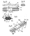
- EP1935596B1 EP1935596B1 EP07024937A EP07024937A EP1935596B1 EP 1935596 B1 EP1935596 B1 EP 1935596B1 EP 07024937 A EP07024937 A EP 07024937A EP 07024937 A EP07024937 A EP 07024937A EP 1935596 B1 EP1935596 B1 EP 1935596B1
- Authority
- EP
- European Patent Office
- Prior art keywords
- chipping
- feed
- tree trunks
- delivery
- drive
- Prior art date
- Legal status (The legal status is an assumption and is not a legal conclusion. Google has not performed a legal analysis and makes no representation as to the accuracy of the status listed.)
- Not-in-force
Links
Images


Classifications
-
- B—PERFORMING OPERATIONS; TRANSPORTING
- B27—WORKING OR PRESERVING WOOD OR SIMILAR MATERIAL; NAILING OR STAPLING MACHINES IN GENERAL
- B27L—REMOVING BARK OR VESTIGES OF BRANCHES; SPLITTING WOOD; MANUFACTURE OF VENEER, WOODEN STICKS, WOOD SHAVINGS, WOOD FIBRES OR WOOD POWDER
- B27L11/00—Manufacture of wood shavings, chips, powder, or the like; Tools therefor
- B27L11/002—Transporting devices for wood or chips
-
- B—PERFORMING OPERATIONS; TRANSPORTING
- B27—WORKING OR PRESERVING WOOD OR SIMILAR MATERIAL; NAILING OR STAPLING MACHINES IN GENERAL
- B27L—REMOVING BARK OR VESTIGES OF BRANCHES; SPLITTING WOOD; MANUFACTURE OF VENEER, WOODEN STICKS, WOOD SHAVINGS, WOOD FIBRES OR WOOD POWDER
- B27L11/00—Manufacture of wood shavings, chips, powder, or the like; Tools therefor
- B27L11/005—Tools therefor
-
- B—PERFORMING OPERATIONS; TRANSPORTING
- B27—WORKING OR PRESERVING WOOD OR SIMILAR MATERIAL; NAILING OR STAPLING MACHINES IN GENERAL
- B27L—REMOVING BARK OR VESTIGES OF BRANCHES; SPLITTING WOOD; MANUFACTURE OF VENEER, WOODEN STICKS, WOOD SHAVINGS, WOOD FIBRES OR WOOD POWDER
- B27L11/00—Manufacture of wood shavings, chips, powder, or the like; Tools therefor
- B27L11/02—Manufacture of wood shavings, chips, powder, or the like; Tools therefor of wood shavings or the like
Definitions
- the invention relates to a device and a method for comminuting logs according to the preamble of claim 1 (see, eg EP-A1 649 933 ).
- a device for comminuting smaller wood material, in particular branches, with a rotary driven shredder for shredding the wood material, a conveyor for transporting the wood material to be shredded to the crusher, and a rotary driven discharger for discharging shredded wood material, and a drive means for driving the crushing device, the conveyor, and the discharge device are known as stationary, non-mobile wood crushing machines.
- the invention has for its object to prevent ingress of unwanted foreign matter in the cutting device of the wood shredder and thereby avoid damage to the knife edges.
- the inventive device for shredding logs comprises a shredding device having a cutting device with a plurality of knife edges, which are arranged or formed on the circumference of a rotary driven knife rotor, as well as a discharge device for discharging the shredded wood material, and a drive device for the shredding device and / or the discharge device, wherein the rotational drive axes of crushing device and discharge device are arranged transversely to each other, and is characterized in that the shredding device with respect to the feeder arranged electrically isolated or formed, and one on a drive control of Supply device and / or the shredding device acting detector circuit is provided, wherein between the shredder and the feeder, an electrical voltage is applied, and the detector circuit detects the electric current flow due to a penetrating between shredder and the feeder foreign body and the drive control of the feeder and / or the shredder in the sense of an automatic stopping, stopping, or driving back the shredder controls.
- the invention it is possible to prevent the penetration of undesirable foreign bodies
- an electrical voltage is applied between the cutting device and the feed device, and an electrical current flow through the detector circuit is detected by a foreign body penetrating between the cutting device and the feed device.
- an electromagnetic resonator for generating an electromagnetic field is provided, and the detector circuit detects a disturbance of the electromagnetic field by an electrically conductive or magnetic foreign body.
- an electromagnetic transmitter which applies an electromagnetic oscillation to the electrically conductive or magnetic foreign body, and the detector circuit detects an electromagnetic field signal induced by the electromagnetically excited foreign body.
- the device 1 for shredding logs 8 comprises a commutating device 9 for comminuting the wood material 8, which is rotationally driven about a plane (perpendicular to the plane of the drawing) and has a conveyor belt 16 and a conveyor roller 2 for transporting the material crushing wood material 8 to the crusher 9, a about a (arranged in the plane of rotation) 3A rotationally driven discharge device 3 for discharging the crushed wood material 8A, and an electromotive drive means 6 for driving the crusher 9, optionally the conveyor 2, 16, and the discharge device 3.
- the rotational drive shaft 9A of the crusher 9 and the rotational drive axis 3A of the discharge device 3 are arranged transversely to each other.
- a conveyor 16 is provided for the transport of the wood trunk to be shredded 8 to the shredding device, in the form of a belt conveyor 16, via which the log 8 of the shredder 9 is supplied.
- a drying device 10 assigned to the discharge device 3 is provided, wherein the heat energy emitted or generated by the drive device 6 during operation can be fed to the drying device 10 for drying the comminuted wood material 8A.
- the drive device 6 has a cooling water circuit 11 with a cooling water inlet 10 A and a cooling water outlet 10 B for cooling the drive units, wherein the drying device 10 has a provided in the cooling water circuit 11 heat exchanger 10 C.
- the drying device 10 or the heat exchanger is in the form of a trough open to one side (in the figures the upper side), the discharge device 3 being accommodated in the trough or extending in the trough.
- the discharge device 3 has a screw conveyor device, specifically the screw conveyor device has two screw shafts 3.1 and 3.2, which rotate in opposite directions to each other, wherein the two screw shafts 3.1 and 3.2 are arranged or mounted within the drying device 10 in the form of a trough.
- the discharge device 3 is connected to a flow-driven ejection means 5 such as in particular a fan 4, with which the crushed wood material 8 is preferably thrown onto a (not shown) loading area of a towing vehicle or vehicle trailer.
- a flow-driven ejection means 5 such as in particular a fan 4, with which the crushed wood material 8 is preferably thrown onto a (not shown) loading area of a towing vehicle or vehicle trailer.
- the ejection means 5 may also be formed in the form of an ejection belt 7, as shown by dashed lines in Figure 1.
- the rotational drive axis 4A of the flow-driven conveying means 4 is arranged transversely to the rotational drive axis 9A of the comminution device 9, this in turn being arranged transversely to the axis of rotation 3A of the screw shafts.
- the discharge device 3 is associated with a spraying device 13 for spraying the wood material 8 with a liquid or fluid agent 14, which spray 13 has a plurality of distributed over the length of the discharge device 3 and / or conveyor arranged spray heads 15, wherein the spray heads 15 on the subsidized wood material 8 act.
- the liquid or fluid agent 14 may be tempered, wherein the heat energy required for the temperature control is at least partially recovered and / or branched off from the heat energy emitted or generated by the drive device 6 during operation.
- the active ingredient 14 has a means for reducing or preventing the mold growth of the wood material 8.
- the crushing device 1, the conveyor 16, the rotationally driven discharge device 3, the ejection means 4, 5, and the drive units of the drive device 6 are all arranged on a (not shown) train or trailer vehicle, wherein the rotational drive axis 3A of the discharge device approximately in the direction of travel of the towing or towing vehicle is arranged, while the rotational drive axis 9A of the crushing device is arranged approximately transversely to the direction of travel of the towing vehicle or trailer.
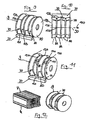
- the shredding device 9 for crushing logs or long wood 8 has a plurality of carbide blades 30 which are arranged or formed on the circumference of a rotary-driven knife rotor 70.
- the knife edges 80 of the hard metal blades 30 are arranged at an angle relative to the axis of rotation 90 of the knife rotor 70 at a predetermined angle.
- the knife edges 80 of the rotor 70 are associated with counter-cutting edges 120 of a counter-blade 20, and indeed the angular position of the relevant counter-blade 120 is adapted to that of the corresponding blade edge 80.
- the rotor body of the rotor 70 is composed of a plurality of rotor disks 130, in particular two different disk diameters, the rotor disks 130 being arranged side by side in such a way that a rotor disk 13A with a larger rotor diameter follows a rotor disk 13B with a smaller rotor diameter.
- the hard metal blades 30 are suitably fixed, e.g. by screwing, clamping, riveting, soldering or other known manner of connection.
- the knife edges 80 of the hard metal blades 30 in the axial direction 100 of the rotor in series alternately or alternately arranged such that the angular position of immediately adjacent knife edges 8 A and 8 B is different.
- the knife edges 8 C and 8 D of the hard metal blades 30 in the circumferential direction 110 of the rotor 70 are arranged alternately or alternately offset distributed over the circumference.
- the respective counter-blade 120 is also obliquely formed to ensure an exact cut (see. Fig. 12 ).
- FIGS. 13 and 14 is shown a further preferred embodiment of the device according to the invention.
- the comminuting device 9 is arranged or formed in an electrically insulated manner relative to the feed device 2 by means of an electrical insulation 40, which is indicated only schematically in FIGS. 13 and 14.
- the shredding device 9 is electrically / magnetically isolated by a provided between the storage 31 of the shredder 9 and a chassis 50 insulation mat or insulation film 40 from the other components of the wood shredder according to the invention.
- an electrical voltage U is applied between the shredder 9 and the feeder 2. If a metallic foreign body 17 is now drawn in and touches the comminution unit 9 and another component of the wood comminution machine, the circuit is closed and an electrical signal can be detected by the detector circuit 110. In response to this signal, the intake by the conveyor 2 and / or the comminution unit 1 is immediately stopped or retracted, and thus prevents damage to the machine 9. Thus, an electrical current flow through the detector circuit 110 is detected and evaluated by a foreign body 17 penetrating between the cutting device 9 and the feed device 2.
Landscapes
- Engineering & Computer Science (AREA)
- Life Sciences & Earth Sciences (AREA)
- Manufacturing & Machinery (AREA)
- Mechanical Engineering (AREA)
- Wood Science & Technology (AREA)
- Forests & Forestry (AREA)
- Debarking, Splitting, And Disintegration Of Timber (AREA)
- Crushing And Pulverization Processes (AREA)
- Disintegrating Or Milling (AREA)
Description
- Die Erfindung betrifft eine Vorrichtung und ein Verfahren zur Zerkleinerung von Holzstämmen nach dem Oberbegriff von Anspruch 1 (siehe z.B.
EP-A1 649 933 ). - Eine Vorrichtung zur Zerkleinerung von kleinerem Holzmaterial wie insbesondere Zweige, mit einer drehangetriebenen Zerkleinerungseinrichtung für die Zerkleinerung des Holzmaterials, einer Fördereinrichtung für den Transport des zu zerkleinernden Holzmaterials an die Zerkleinerungseinrichtung, und mit einer drehangetriebenen Austragungseinrichtung für die Austragung des zerkleinerten Holzmaterials, und mit einer Antriebseinrichtung für den Antrieb der Zerkleinerungseinrichtung, der Fördereinrichtung, und der Austragungseinrichtung sind als stationäre, nicht mobile Holzzerkleinerungsmaschinen bekannt.
- Der Erfindung liegt die Aufgabe zugrunde, ein Eindringen unerwünschter Fremdkörper in die Schneideeinrichtung der Holzzerkleinerungsmaschine zu verhindern und dadurch eine Beschädigung der Messerschneiden vermeiden.
- Diese Aufgabe wird durch eine Vorrichtung zur Zerkleinerung von Holzstämmen nach Anspruch 1 gelöst.
- Die erfindungsgemäße Vorrichtung zur Zerkleinerung von Holzstämmen umfasst eine Zerkleinerungseinrichtung, die eine Schneideeinrichtung mit einer Vielzahl von Messerschneiden aufweist, die am Umfang eines drehangetriebenen Messerrotors angeordnet bzw. ausgebildet sind, sowie eine Austragungseinrichtung für die Austragung des zerkleinerten Holzmaterials, und eine Antriebseinrichtung für die Zerkleinerungseinrichtung und/oder die Austragungseinrichtung, wobei die Drehantriebsachsen von Zerkleinerungseinrichtung und Austragungseinrichtung quer zueinander angeordnet sind, und zeichnet sich dadurch aus, dass die Zerkleinerungseinrichtung gegenüber der Zuführeinrichtung elektrisch isoliert angeordnet bzw. ausgebildet ist, und eine auf eine Antriebssteuerung der Zuführeinrichtung und/oder der Zerkleinerungseinrichtung wirkende Detektorschaltung vorgesehen ist, wobei zwischen der Zerkleinerungseinrichtung und der Zuführeinrichtung eine elektrische Spannung angelegt ist, und die Detektorschaltung den elektrischen Stromfluss aufgrund eines zwischen Zerkleinerungseinrichtung und die Zuführeinrichtung eindringenden Fremdkörpers erfasst und die Antriebssteuerung der Zuführeinrichtung und/oder der Zerkleinerungseinrichtung im Sinne eines selbsttätigen Anhaltens, Abstellens, oder Zurückfahrens der Zerkleinerungseinrichtung steuert. Mit der Erfindung gelingt es, ein Eindringen unerwünschter Fremdkörper in die Schneideeinrichtung der Holzzerkleinerungsmaschine zu verhindern und dadurch eine Beschädigung der Messerschneiden vermeiden.
- Dem Prinzip der Erfindung folgend ist vorgesehen, dass zwischen der Schneideeinrichtung und der Zuführeinrichtung eine elektrische Spannung angelegt ist, und durch einen zwischen die Schneideeinrichtung und die Zuführeinrichtung eindringenden Fremdkörper ein elektrischer Stromfluss durch die Detektorschaltung erfasst wird.
- Darüber hinaus oder auch alternativ kann nach der Erfindung vorgesehen sein, dass ein elektromagnetischer Resonator zur Erzeugung eines elektromagnetischen Feldes vorgesehen ist, und die Detektorschaltung eine Störung des elektromagnetischen Feldes durch einen elektrisch leitenden oder magnetischen Fremdkörper erfasst.
- In einer anderen vorteilhaften Weiterführung der Erfindung kann vorgesehen sein, dass ein elektromagnetischer Sender vorgesehen ist, der den elektrisch leitenden oder magnetischen Fremdkörper mit einer elektromagnetischen Schwingung beaufschlagt, und die Detektorschaltung ein von dem elektromagnetisch angeregten Fremdkörper induziertes elektromagnetisches Feldsignal erfasst.
- Weitere vorteilhafte Ausgestaltungen der erfindungsgemäßen Vorrichtung und des Verfahrens sind in den weiteren Unteransprüchen angegeben.
- Die Erfindung wird nachfolgend anhand von in der Zeichnung dargestellten Ausführungsbeispielen näher erläutert. Es zeigt:
- Fig. 1
- eine schematische Vorderansicht der erfindungsge- mäßen Vorrichtung nach einem ersten Ausführung- beispiel;
- Fig. 2
- eine schematische Daraufsicht der erfindungsge- mäßen Vorrichtung nach dem ersten Ausführungsbei spiel;
- Fig. 3 A, B, C
- eine schematische Vorder-, Schnitt- und Daraufsicht der erfindungsgemäßen Vorrichtung nach dem ersten Ausführungsbeispiel;
- Fig. 4
- eine schematische Schnittansicht der erfindungsge- mäßen Vorrichtung nach dem ersten Ausführungsbei spiel;
- Fig. 5
- eine schematische Perspektivansicht der erfindungs- gemäßen Vorrichtung nach dem ersten Ausführungs- beispiel;
- Fig. 9
- eine schematische Ansicht der Zerkleinerungs- einrichtung nach den Ausführungsbeispielen;
- Fig. 10
- eine Schnittansicht der Zerkleinerungseinrichtung;
- Fig. 11
- eine schematische Ansicht einer weiteren Zerklei- nerungseinrichtung nach den Ausführungsbeispielen;
- Fig. 12
- das Schnittbild eines mit der Erfindung geschnitte nes Holzes;
- Fig. 13
- eine schematische Schnittansicht der erfindungs- gemäßen Vorrichtung nach einem weiteren Ausfüh rungsbeispiel; und
- Fig. 14
- eine vergrößert dargestellte Teilansicht des in
Fig. 13 dargestellten Ausführungsbeispieles. - In den Figuren sind bevorzugte Ausführungsbeispiele der erfindungsgemäßen Vorrichtung dargestellt, wobei sich gleiche Bezugsziffern auf gleiche Bestandteile der Erfindung beziehen.
- Die Vorrichtung 1 zur Zerkleinerung von Holzstämmen 8 umfasst eine um eine (senkrecht zur Zeichenebene angeordnete) Drehachse 9A drehangetriebene, mit Spaltmessern 9B versehene Zerkleinerungseinrichtung 9 für die Zerkleinerung des Holzmaterials 8, eine ein Förderband 16 und eine Förderwalze 2 umfassende Fördereinrichtung für den Transport des zu zerkleinernden Holzmaterials 8 an die Zerkleinerungseinrichtung 9, eine um eine (in der Zeichenebene angeordnete) Drehachse 3A drehangetriebene Austragungseinrichtung 3 für die Austragung des zerkleinerten Holzmaterials 8A, und eine elektromotorische Antriebseinrichtung 6 für den Antrieb der Zerkleinerungseinrichtung 9, gegebenenfalls der Fördereinrichtung 2, 16, und der Austragungseinrichtung 3. Die Drehantriebsachse 9A der Zerkleinerungseinrichtung 9 und die Drehantriebsachse 3A der Austragungseinrichtung 3 sind quer zueinander angeordnet. Bei den dargestellten Ausführungsbeispielen ist eine Fördereinrichtung 16 für den Transport des zu zerkleinernden Holzstammes 8 an die Zerkleinerungseinrichtung vorgesehen, und zwar in Form einer Bandfördereinrichtung 16, über welche der Holzstamm 8 der Zerkleinerungseinrichtung 9 zugeführt wird.
- Es ist eine der Austragungseinrichtung 3 zugeordnete Trocknungseinrichtung 10 vorgesehen, wobei die von der Antriebseinrichtung 6 während des Betriebes abgegebene bzw. erzeugte Wärmeenergie der Trocknungseinrichtung 10 für die Trocknung des zerkleinerten Holzmaterials 8A zuführbar ist. Die Antriebseinrichtung 6 besitzt einen Kühlwasserkreislauf 11 mit einem Kühlwassereintritt 10 A und einem Kühlwasseraustritt 10 B zur Kühlung der Antriebsaggregate, wobei die Trocknungseinrichtung 10 einen in dem Kühlwasserkreislauf 11 vorgesehenen Wärmetauscher 10 C aufweist. Die Trocknungseinrichtung 10 bzw. der Wärmetauscher ist in der Form einer nach einer Seite (in den Figuren die obere Seite) offenen Wanne ausgebildet, wobei die Austragungseinrichtung 3 in der Wanne aufgenommen ist oder in der Wanne verläuft.
- Bei dem in den
Figuren 1 bis 5 dargestellten Ausführungsbeispiel weist die Austragungseinrichtung 3 eine Schneckenfördereinrichtung auf, und zwar hat die Schneckenfördereinrichtung zwei gegenläufig zueinander drehangetriebene Schneckenwelle 3.1 und 3.2, wobei die beiden Schneckenwellen 3.1 und 3.2 innerhalb der in der Form einer Wanne ausgebildeten Trocknungseinrichtung 10 angeordnet bzw. gelagert sind. - Die Austragungseinrichtung 3 ist an ein strömungsangetriebenes Auswurfmittel 5 wie insbesondere ein Gebläse 4 angeschlossen, mit welchem das zerkleinerte Holzmaterial 8 vorzugsweise auf eine (nicht näher dargestellten) Ladefläche eines zugfahrzeuges bzw. Fahrzeuganhängers geworfen wird. Anstelle eines Gebläses 4 kann das Auswurfmittel 5 auch in der Form eines Auswurfbandes 7 ausgebildet sein, wie dies in Figur 1 strichliert dargestellt ist.
- Die Drehantriebsachse 4A des strömungsangetriebenen Fördermittels 4 ist quer zur Drehantriebsachse 9A der Zerkleinerungseinrichtung 9 angeordnet, wobei diese wiederum quer zur Drehachse 3A der Schneckenwellen angeordnet ist.
- Der Austragungseinrichtung 3 ist eine Sprüheinrichtung 13 zum Besprühen des Holzmaterials 8 mit einem flüssigen oder fluiden Wirkstoff 14 zugeordnet, welche Sprüheinrichtung 13 mehrere über die Länge der Austragungseinrichtung 3 und/oder der Fördereinrichtung verteilt angeordnete Sprühköpfe 15 aufweist, wobei die Sprühköpfe 15 auf das geförderte Holzmaterial 8 wirken. Von Vorteil kann der flüssige oder fluide Wirkstoff 14 temperiert sein, wobei die zur Temperierung erforderliche Wärmeenergie wenigstens teilweise aus der von der Antriebseinrichtung 6 während des Betriebes abgegebenen bzw. erzeugten Wärmeenergie gewonnen und/oder abgezweigt wird. Der Wirkstoff 14 weist ein Mittel zur Verminderung oder Verhinderung der Schimmelbildung des Holzmaterials 8 auf.
- Die Zerkleinerungseinrichtung 1, die Fördereinrichtung 16, die drehangetriebene Austragungseinrichtung 3, die Auswurfmittel 4, 5, sowie die Antriebsaggregate der Antriebseinrichtung 6 sind allesamt auf einem (nicht näher dargestellten) Zug- oder Anhängerfahrzeug angeordnet, wobei die Drehantriebsachse 3A der Austragungseinrichtung annähernd in Fahrtrichtung des Zug- oder Anhängerfahrzeuges angeordnet ist, während die Drehantriebsachse 9A der Zerkleinerungseinrichtung annähernd quer zur Fahrtrichtung des Zug- oder Anhängerfahrzeuges angeordnet ist.
- In den
Fig. 9 bis 12 sind Einzelheiten der in allen Ausführungsbeispielen der Erfindung verwendeten Zerkleinerungseinrichtung 9 dargestellt. Die erfindungsgemäße Zerkleinerungseinrichtung 9 zum Zerkleinern von Stammholz bzw. Langholz 8 besitzt eine Vielzahl von Hartmetallmessern 30, die am Umfang eines drehangetriebenen Messerrotors 70 angeordnet bzw. ausgebildet sind. Die Messerschneiden 80 der Hartmetallmesser 30 sind gegenüber der Drehachse 90 des Messerrotors 70 unter einem vorbestimmten Winkel schräg angeordnet. Den Messerschneiden 80 des Rotors 70 sind Gegenschneiden 120 eines Gegenmessers 20 zugeordnet, und zwar ist die Winkelstellung der betreffenden Gegenschneide 120 derjenigen der entsprechenden Messerschneide 80 angepasst. - Der Rotorkörper des Rotors 70 setzt sich aus mehreren Rotorscheiben 130 mit insbesondere zwei unterschiedlichen Scheibendurchmessern zusammen, wobei die Rotorscheiben 130 nebeneinander dergestalt angeordnet sind, dass eine Rotorscheibe 13A mit einem größeren Rotordurchmesser auf eine Rotorscheibe 13B mit einem kleineren Rotordurchmesser folgt. Am Randbereich der mit einem vorbestimmten Abstand voneineinander montierten Rotorscheiben 13A und 13B sind die Hartmetallmesser 30 auf geeignete Weise befestigt, z.B. durch Schraub-, Klemm-, Niet-, Löt- oder sonstige an sich bekannte Verbindungsweise.
- Bei dem in den
Fig. 9 und 10 dargestellten Ausführungsbeispiel der Erfindung sind die Messerschneiden 80 der Hartmetallmesser 30 in axialer Richtung 100 des Rotors in Reihe alternierend bzw. wechselweise dergestalt angeordnet, dass die winkelstellung unmittelbar benachbarter Messerschneiden 8 A und 8 B unterschiedlich ist. - Bei dem in
Fig. 11 dargestellten Ausführungsbeispiel der Erfindung sind die Messerschneiden 8 C und 8 D der Hartmetallmesser 30 in Umfangsrichtung 110 des Rotors 70 alternierend bzw. wechselweise versetzt über den Umfang verteilt angeordnet. - Durch die schräge Anordnung der Schneidwerkzeuge 80 zu den Rotorscheiben 130 wird ein Schnitt schräg zur Faser des Stammholzes 8 möglich, wodurch der Kraftaufwand vermindert wird. Die jeweilige Gegenschneide 120 ist ebenfalls schräg ausgebildet, um einen exakten Schnitt zu gewährleisten (vgl.
Fig. 12 ). - In
Fig. 13 und 14 ist ein weiteres bevorzugtes Ausführungsbeispiel der erfindungsgemäßen Vorrichtung dargestellt. Die Zerkleinerungseinrichtung 9 ist vermittels einer in den Figuren 13 und 14 nur schematisch angedeuteten elektrischen Isolation 40 gegenüber der Zuführeinrichtung 2 elektrisch isoliert angeordnet bzw. ausgebildet. Beim dargestellten Ausführungsbeispiel ist die Zerkleinerungseinrichtung 9 durch eine zwischen der Lagerung 31 der Zerkleinerungseinrichtung 9 und einem Chassis 50 vorgesehene Isolationsmatte oder Isolationsfolie 40 von den anderen Bauteilen der erfindungsgemäßen Holzzerkleinerungsmaschine elektrisch/magnetisch isoliert. - Es ist eine auf die (nicht näher dargestellte) Antriebssteuerung der Zerkleinerungseinrichtung 9 wirkende Detektorschaltung 110 vorgesehen, welche ein von einem elektrisch leitenden oder magnetischen Fremdkörper 17 verursachtes und/oder beeinflusstes elektrisches oder magnetisches Signal detektiert, und als Reaktion hierauf die Antriebssteuerung der Zerkleinerungseinrichtung 9 im Sinne eines selbsttätigen Anhaltens, Abstellens oder Zurückfahrens der Zerkleinerungsvorrichtung 9 steuert.
- Beim dargestellten Ausführungsbeispiel ist zwischen der Zerkleinerungseinrichtung 9 und der Zuführeinrichtung 2 eine elektrische Spannung U angelegt. Wird nun ein metallischer Fremdkörper 17 eingezogen und berührt die Zerkleinerungseinheit 9 und ein anderes Bauteil der Holzzerkleinerungsmaschine, so wird der Stromkreis geschlossen und es kann ein elektrisches Signal von der Detektorschaltung 110 erfasst werden. Auf dieses Signal hin wird der Einzug durch die Fördereinrichtung 2 und/oder die Zerkleinerungseinheit 1 unverzüglich angehalten bzw. zurückgefahren, und auf diese Weise Schäden an der Maschine 9 verhindert. Durch einen zwischen die Schneideinrichtung 9 und die Zuführeinrichtung 2 eindringenden Fremdkörper 17 wird somit ein elektrischer Stromfluss durch die Detektorschaltung 110 erfasst und ausgewertet.
Claims (2)
- Vorrichtung zur Zerkleinerung von Holzstämmen (8) mit einer Zuführeinrichtung (2) für die Holzstämme (8), einer Zerkleinerungseinrichtung (9), die eine Schneideeinrichtung mit einer Vielzahl von Messerschneiden (80) aufweist, die am Umfang eines drehangetriebenen Messerrotors (90) angeordnet bzw. ausgebildet sind, sowie einer Austragungseinrichtung (3) für die Austragung des zerkleinerten Holzmaterials (8A), und einer Antriebseinrichtung (6) für die Zerkleinerungseinrichtung (9) und/oder die Austragungseinrichtung (3), wobei die Drehantriebsachsen (9A, 3A) von Zerkleinerungseinrichtung (9) und Austragungseinrichtung (3) quer zueinander angeordnet sind, dadurch gekennzeichnet, dass die Zerkleinerungseinrichtung (9) gegenüber der Zuführeinrichtung (2) elektrisch isoliert angeordnet bzw. ausgebildet ist, und eine auf eine Antriebssteuerung der Zuführeinrichtung (2) und/oder der Zerkleinerungseinrichtung (9) wirkende Detektorschaltung (110) vorgesehen ist, wobei zwischen der Zerkleinerungseinrichtung (9) und der Zuführeinrichtung (2) eine elektrische Spannung (U) angelegt ist, und die Detektorschaltung (110) den elektrischen Stromfluss aufgrund, eines zwischen Zerkleinerungseinrichtung (9) und die Zuführeinrichtung (2) eindringenden Fremdkörpers (17) erfasst und die Antriebssteuerung der Zuführeinrichtung (2) und/oder der Zerkleinerungseinrichtung (9) im Sinne eines selbsttätigen Anhaltens, Abstellens, oder Zurückfahrens der Zerkleinerungseinrichtung (9) steuert.
- Vorrichtung zur Zerkleinerung von Holzstämmen (8) nach Anspruch 1, dadurch gekennzeichnet, dass die Zerkleinerungseinrichtung (9) durch eine zwischen der Lagerung (30) der Zerkleinerungseinrichtung (9) und einem Chassis (50) vorgesehene Isolationsmatte oder Isolationsfolie (40) gegenüber der Zuführeinrichtung (2) elektrisch isoliert angeordnet bzw. ausgebildet ist.
Applications Claiming Priority (1)
| Application Number | Priority Date | Filing Date | Title |
|---|---|---|---|
| DE102006062685 | 2006-12-22 |
Publications (2)
| Publication Number | Publication Date |
|---|---|
| EP1935596A1 EP1935596A1 (de) | 2008-06-25 |
| EP1935596B1 true EP1935596B1 (de) | 2010-09-29 |
Family
ID=39145153
Family Applications (1)
| Application Number | Title | Priority Date | Filing Date |
|---|---|---|---|
| EP07024937A Not-in-force EP1935596B1 (de) | 2006-12-22 | 2007-12-21 | Vorrichtung zur Zerkleinerung von Holzstämmen |
Country Status (3)
| Country | Link |
|---|---|
| EP (1) | EP1935596B1 (de) |
| AT (1) | ATE482804T1 (de) |
| DE (1) | DE502007005181D1 (de) |
Families Citing this family (2)
| Publication number | Priority date | Publication date | Assignee | Title |
|---|---|---|---|---|
| FR2933326A1 (fr) * | 2008-07-02 | 2010-01-08 | Alain Lejosne | Appareil de production de granules a partir de vegetaux |
| DE102010050786B3 (de) * | 2010-11-10 | 2012-03-15 | Hogha Gmbh | Austragvorrichtung für eine Holzhackmaschine |
Family Cites Families (4)
| Publication number | Priority date | Publication date | Assignee | Title |
|---|---|---|---|---|
| DE4416195A1 (de) * | 1993-05-18 | 1994-11-24 | Josef Gres | Verfahren und Vorrichtung zum Fällen und Verarbeiten von Bäumen |
| US5667152A (en) * | 1995-05-30 | 1997-09-16 | Mooring; Jonathan E. | Safety system for a wood chipper |
| WO2004082909A1 (de) * | 2003-03-20 | 2004-09-30 | Johann Kirchmayr | Zerkleinerungseinrichtung für stückholz |
| DE102004050926A1 (de) * | 2004-10-19 | 2006-04-20 | Georg Weiss Gmbh | Zerkleinerungsmaschine |
-
2007
- 2007-12-21 AT AT07024937T patent/ATE482804T1/de active
- 2007-12-21 EP EP07024937A patent/EP1935596B1/de not_active Not-in-force
- 2007-12-21 DE DE502007005181T patent/DE502007005181D1/de active Active
Also Published As
| Publication number | Publication date |
|---|---|
| EP1935596A1 (de) | 2008-06-25 |
| DE502007005181D1 (de) | 2010-11-11 |
| ATE482804T1 (de) | 2010-10-15 |
Similar Documents
| Publication | Publication Date | Title |
|---|---|---|
| EP0916252B1 (de) | Häcksler zum Zerkleinern von Halmgut, vorzugsweise von Stroh | |
| EP3061581B1 (de) | Zerkleinerer | |
| EP2468409B1 (de) | Vorrichtung zum Zerkleinern von Teilen beliebiger Art | |
| DE19612024C2 (de) | Zerkleinerungsgerät | |
| EP1935595B1 (de) | Vorrichtung und Verfahren zur Zerkleinerung von Holzstämmen | |
| DE2256267C3 (de) | Mit Scherwirkung arbeitender Zerkleinerer | |
| DE60105981T2 (de) | Vorrichtung zum zerschneiden von pflanzengut | |
| EP1935596A1 (de) | Vorrichtung und Verfahren zur Zerkleinerung von Holzstämmen | |
| DE60309674T2 (de) | Schneideeinrichtung zum zerkleinern von abfallmaterial | |
| EP2058096A2 (de) | Hackmaschine | |
| EP2564930B1 (de) | Häcksler | |
| DE2309257A1 (de) | Granuliervorrichtung mit schneckenfoerderer | |
| EP1080630B1 (de) | Verfahren zum Einstellen des Schneidspaltes an Häckslern | |
| DE3527772A1 (de) | Vorrichtung zum zerkleinern von abfaellen | |
| DE202017000378U1 (de) | Messertrommel zum Zerkleinern von Holz | |
| EP0175313B1 (de) | Vorrichtung zum Zerkleinern von Abfall | |
| WO2002076617A1 (de) | Vorrichtung zum zerkleinern von kunststoffgebilden mit geringer materialstärke | |
| EP3384753B1 (de) | Häcksel-, sammel- und transportmaschine für häckselgut | |
| DE202006001147U1 (de) | Vorrichtung zum Zerkleinern von Teilen beliebiger Art | |
| EP1782680B1 (de) | Vorrichtung zum Zerkleinern von Pflanzengut in Form von Grünmasse und/oder Schwachholz | |
| EP1649933A1 (de) | Zerkleinerungsmaschine mit konischem Rotor | |
| EP0630686A1 (de) | Gartenabfallzerkleinerer | |
| DE102024120308A1 (de) | Hackschnitzelrotor für ein Hackerfahrzeug und zum Zerhacken von, insbesondere stamm- und/oder astartigen, Rohholz zur Herstellung von Hackschnitzeln | |
| EP4218395A1 (de) | Selbstfahrender feldhäcksler sowie verfahren zu dessen betrieb | |
| DE1511164A1 (de) | Vorrichtung zum Vernichten von Papiergut od.dgl. |
Legal Events
| Date | Code | Title | Description |
|---|---|---|---|
| PUAI | Public reference made under article 153(3) epc to a published international application that has entered the european phase |
Free format text: ORIGINAL CODE: 0009012 |
|
| AK | Designated contracting states |
Kind code of ref document: A1 Designated state(s): AT BE BG CH CY CZ DE DK EE ES FI FR GB GR HU IE IS IT LI LT LU LV MC MT NL PL PT RO SE SI SK TR |
|
| AX | Request for extension of the european patent |
Extension state: AL BA HR MK RS |
|
| AKX | Designation fees paid | ||
| 17P | Request for examination filed |
Effective date: 20081229 |
|
| RBV | Designated contracting states (corrected) |
Designated state(s): AT BE BG CH CY CZ DE DK EE ES FI FR GB GR HU IE IS IT LI LT LU LV MC MT NL PL PT RO SE SI SK TR |
|
| REG | Reference to a national code |
Ref country code: DE Ref legal event code: 8566 |
|
| 17Q | First examination report despatched |
Effective date: 20090402 |
|
| RTI1 | Title (correction) |
Free format text: APPARATUS FOR CHIPPING TREE TRUNKS |
|
| GRAP | Despatch of communication of intention to grant a patent |
Free format text: ORIGINAL CODE: EPIDOSNIGR1 |
|
| GRAS | Grant fee paid |
Free format text: ORIGINAL CODE: EPIDOSNIGR3 |
|
| GRAA | (expected) grant |
Free format text: ORIGINAL CODE: 0009210 |
|
| AK | Designated contracting states |
Kind code of ref document: B1 Designated state(s): AT BE BG CH CY CZ DE DK EE ES FI FR GB GR HU IE IS IT LI LT LU LV MC MT NL PL PT RO SE SI SK TR |
|
| REG | Reference to a national code |
Ref country code: GB Ref legal event code: FG4D Free format text: NOT ENGLISH |
|
| REG | Reference to a national code |
Ref country code: CH Ref legal event code: EP |
|
| REG | Reference to a national code |
Ref country code: IE Ref legal event code: FG4D Free format text: LANGUAGE OF EP DOCUMENT: GERMAN |
|
| REF | Corresponds to: |
Ref document number: 502007005181 Country of ref document: DE Date of ref document: 20101111 Kind code of ref document: P |
|
| PG25 | Lapsed in a contracting state [announced via postgrant information from national office to epo] |
Ref country code: FI Free format text: LAPSE BECAUSE OF FAILURE TO SUBMIT A TRANSLATION OF THE DESCRIPTION OR TO PAY THE FEE WITHIN THE PRESCRIBED TIME-LIMIT Effective date: 20100929 Ref country code: LT Free format text: LAPSE BECAUSE OF FAILURE TO SUBMIT A TRANSLATION OF THE DESCRIPTION OR TO PAY THE FEE WITHIN THE PRESCRIBED TIME-LIMIT Effective date: 20100929 |
|
| REG | Reference to a national code |
Ref country code: NL Ref legal event code: VDEP Effective date: 20100929 |
|
| LTIE | Lt: invalidation of european patent or patent extension |
Effective date: 20100929 |
|
| PG25 | Lapsed in a contracting state [announced via postgrant information from national office to epo] |
Ref country code: SI Free format text: LAPSE BECAUSE OF FAILURE TO SUBMIT A TRANSLATION OF THE DESCRIPTION OR TO PAY THE FEE WITHIN THE PRESCRIBED TIME-LIMIT Effective date: 20100929 |
|
| PG25 | Lapsed in a contracting state [announced via postgrant information from national office to epo] |
Ref country code: LV Free format text: LAPSE BECAUSE OF FAILURE TO SUBMIT A TRANSLATION OF THE DESCRIPTION OR TO PAY THE FEE WITHIN THE PRESCRIBED TIME-LIMIT Effective date: 20100929 Ref country code: GR Free format text: LAPSE BECAUSE OF FAILURE TO SUBMIT A TRANSLATION OF THE DESCRIPTION OR TO PAY THE FEE WITHIN THE PRESCRIBED TIME-LIMIT Effective date: 20101230 Ref country code: SE Free format text: LAPSE BECAUSE OF FAILURE TO SUBMIT A TRANSLATION OF THE DESCRIPTION OR TO PAY THE FEE WITHIN THE PRESCRIBED TIME-LIMIT Effective date: 20100929 |
|
| REG | Reference to a national code |
Ref country code: IE Ref legal event code: FD4D |
|
| PG25 | Lapsed in a contracting state [announced via postgrant information from national office to epo] |
Ref country code: RO Free format text: LAPSE BECAUSE OF FAILURE TO SUBMIT A TRANSLATION OF THE DESCRIPTION OR TO PAY THE FEE WITHIN THE PRESCRIBED TIME-LIMIT Effective date: 20100929 Ref country code: IS Free format text: LAPSE BECAUSE OF FAILURE TO SUBMIT A TRANSLATION OF THE DESCRIPTION OR TO PAY THE FEE WITHIN THE PRESCRIBED TIME-LIMIT Effective date: 20110129 Ref country code: EE Free format text: LAPSE BECAUSE OF FAILURE TO SUBMIT A TRANSLATION OF THE DESCRIPTION OR TO PAY THE FEE WITHIN THE PRESCRIBED TIME-LIMIT Effective date: 20100929 Ref country code: SK Free format text: LAPSE BECAUSE OF FAILURE TO SUBMIT A TRANSLATION OF THE DESCRIPTION OR TO PAY THE FEE WITHIN THE PRESCRIBED TIME-LIMIT Effective date: 20100929 Ref country code: NL Free format text: LAPSE BECAUSE OF FAILURE TO SUBMIT A TRANSLATION OF THE DESCRIPTION OR TO PAY THE FEE WITHIN THE PRESCRIBED TIME-LIMIT Effective date: 20100929 Ref country code: CZ Free format text: LAPSE BECAUSE OF FAILURE TO SUBMIT A TRANSLATION OF THE DESCRIPTION OR TO PAY THE FEE WITHIN THE PRESCRIBED TIME-LIMIT Effective date: 20100929 Ref country code: IT Free format text: LAPSE BECAUSE OF FAILURE TO SUBMIT A TRANSLATION OF THE DESCRIPTION OR TO PAY THE FEE WITHIN THE PRESCRIBED TIME-LIMIT Effective date: 20100929 Ref country code: PT Free format text: LAPSE BECAUSE OF FAILURE TO SUBMIT A TRANSLATION OF THE DESCRIPTION OR TO PAY THE FEE WITHIN THE PRESCRIBED TIME-LIMIT Effective date: 20110131 |
|
| BERE | Be: lapsed |
Owner name: STEININGER, WERNER Effective date: 20101231 |
|
| PG25 | Lapsed in a contracting state [announced via postgrant information from national office to epo] |
Ref country code: IE Free format text: LAPSE BECAUSE OF FAILURE TO SUBMIT A TRANSLATION OF THE DESCRIPTION OR TO PAY THE FEE WITHIN THE PRESCRIBED TIME-LIMIT Effective date: 20100929 Ref country code: MC Free format text: LAPSE BECAUSE OF NON-PAYMENT OF DUE FEES Effective date: 20101231 Ref country code: ES Free format text: LAPSE BECAUSE OF FAILURE TO SUBMIT A TRANSLATION OF THE DESCRIPTION OR TO PAY THE FEE WITHIN THE PRESCRIBED TIME-LIMIT Effective date: 20110109 |
|
| PLBE | No opposition filed within time limit |
Free format text: ORIGINAL CODE: 0009261 |
|
| STAA | Information on the status of an ep patent application or granted ep patent |
Free format text: STATUS: NO OPPOSITION FILED WITHIN TIME LIMIT |
|
| PG25 | Lapsed in a contracting state [announced via postgrant information from national office to epo] |
Ref country code: PL Free format text: LAPSE BECAUSE OF FAILURE TO SUBMIT A TRANSLATION OF THE DESCRIPTION OR TO PAY THE FEE WITHIN THE PRESCRIBED TIME-LIMIT Effective date: 20100929 Ref country code: DK Free format text: LAPSE BECAUSE OF FAILURE TO SUBMIT A TRANSLATION OF THE DESCRIPTION OR TO PAY THE FEE WITHIN THE PRESCRIBED TIME-LIMIT Effective date: 20100929 |
|
| PG25 | Lapsed in a contracting state [announced via postgrant information from national office to epo] |
Ref country code: BE Free format text: LAPSE BECAUSE OF NON-PAYMENT OF DUE FEES Effective date: 20101231 |
|
| REG | Reference to a national code |
Ref country code: DE Ref legal event code: R097 Ref document number: 502007005181 Country of ref document: DE Effective date: 20110630 |
|
| PG25 | Lapsed in a contracting state [announced via postgrant information from national office to epo] |
Ref country code: MT Free format text: LAPSE BECAUSE OF FAILURE TO SUBMIT A TRANSLATION OF THE DESCRIPTION OR TO PAY THE FEE WITHIN THE PRESCRIBED TIME-LIMIT Effective date: 20100929 |
|
| REG | Reference to a national code |
Ref country code: CH Ref legal event code: PL |
|
| PG25 | Lapsed in a contracting state [announced via postgrant information from national office to epo] |
Ref country code: CY Free format text: LAPSE BECAUSE OF FAILURE TO SUBMIT A TRANSLATION OF THE DESCRIPTION OR TO PAY THE FEE WITHIN THE PRESCRIBED TIME-LIMIT Effective date: 20100929 |
|
| PG25 | Lapsed in a contracting state [announced via postgrant information from national office to epo] |
Ref country code: BG Free format text: LAPSE BECAUSE OF FAILURE TO SUBMIT A TRANSLATION OF THE DESCRIPTION OR TO PAY THE FEE WITHIN THE PRESCRIBED TIME-LIMIT Effective date: 20100929 Ref country code: HU Free format text: LAPSE BECAUSE OF FAILURE TO SUBMIT A TRANSLATION OF THE DESCRIPTION OR TO PAY THE FEE WITHIN THE PRESCRIBED TIME-LIMIT Effective date: 20110330 Ref country code: LU Free format text: LAPSE BECAUSE OF NON-PAYMENT OF DUE FEES Effective date: 20101221 |
|
| PG25 | Lapsed in a contracting state [announced via postgrant information from national office to epo] |
Ref country code: CH Free format text: LAPSE BECAUSE OF NON-PAYMENT OF DUE FEES Effective date: 20111231 Ref country code: LI Free format text: LAPSE BECAUSE OF NON-PAYMENT OF DUE FEES Effective date: 20111231 Ref country code: TR Free format text: LAPSE BECAUSE OF FAILURE TO SUBMIT A TRANSLATION OF THE DESCRIPTION OR TO PAY THE FEE WITHIN THE PRESCRIBED TIME-LIMIT Effective date: 20100929 |
|
| PG25 | Lapsed in a contracting state [announced via postgrant information from national office to epo] |
Ref country code: BG Free format text: LAPSE BECAUSE OF FAILURE TO SUBMIT A TRANSLATION OF THE DESCRIPTION OR TO PAY THE FEE WITHIN THE PRESCRIBED TIME-LIMIT Effective date: 20101229 |
|
| REG | Reference to a national code |
Ref country code: FR Ref legal event code: PLFP Year of fee payment: 9 |
|
| REG | Reference to a national code |
Ref country code: FR Ref legal event code: PLFP Year of fee payment: 10 |
|
| REG | Reference to a national code |
Ref country code: FR Ref legal event code: PLFP Year of fee payment: 11 |
|
| PGFP | Annual fee paid to national office [announced via postgrant information from national office to epo] |
Ref country code: GB Payment date: 20221220 Year of fee payment: 16 Ref country code: FR Payment date: 20221125 Year of fee payment: 16 |
|
| P01 | Opt-out of the competence of the unified patent court (upc) registered |
Effective date: 20230427 |
|
| PGFP | Annual fee paid to national office [announced via postgrant information from national office to epo] |
Ref country code: DE Payment date: 20231228 Year of fee payment: 17 Ref country code: AT Payment date: 20231228 Year of fee payment: 17 |
|
| GBPC | Gb: european patent ceased through non-payment of renewal fee |
Effective date: 20231221 |
|
| PG25 | Lapsed in a contracting state [announced via postgrant information from national office to epo] |
Ref country code: GB Free format text: LAPSE BECAUSE OF NON-PAYMENT OF DUE FEES Effective date: 20231221 |
|
| PG25 | Lapsed in a contracting state [announced via postgrant information from national office to epo] |
Ref country code: FR Free format text: LAPSE BECAUSE OF NON-PAYMENT OF DUE FEES Effective date: 20231231 |
|
| PG25 | Lapsed in a contracting state [announced via postgrant information from national office to epo] |
Ref country code: GB Free format text: LAPSE BECAUSE OF NON-PAYMENT OF DUE FEES Effective date: 20231221 Ref country code: FR Free format text: LAPSE BECAUSE OF NON-PAYMENT OF DUE FEES Effective date: 20231231 |
|
| REG | Reference to a national code |
Ref country code: DE Ref legal event code: R119 Ref document number: 502007005181 Country of ref document: DE |
|
| REG | Reference to a national code |
Ref country code: AT Ref legal event code: MM01 Ref document number: 482804 Country of ref document: AT Kind code of ref document: T Effective date: 20241221 |
|
| PG25 | Lapsed in a contracting state [announced via postgrant information from national office to epo] |
Ref country code: DE Free format text: LAPSE BECAUSE OF NON-PAYMENT OF DUE FEES Effective date: 20250701 |
|
| PG25 | Lapsed in a contracting state [announced via postgrant information from national office to epo] |
Ref country code: AT Free format text: LAPSE BECAUSE OF NON-PAYMENT OF DUE FEES Effective date: 20241221 |