EP1935528B1 - Method for assembling a bearing ring with a mechanical element - Google Patents
Method for assembling a bearing ring with a mechanical element Download PDFInfo
- Publication number
- EP1935528B1 EP1935528B1 EP07291454A EP07291454A EP1935528B1 EP 1935528 B1 EP1935528 B1 EP 1935528B1 EP 07291454 A EP07291454 A EP 07291454A EP 07291454 A EP07291454 A EP 07291454A EP 1935528 B1 EP1935528 B1 EP 1935528B1
- Authority
- EP
- European Patent Office
- Prior art keywords
- ring
- rim
- annealing
- elements
- assembling
- Prior art date
- Legal status (The legal status is an assumption and is not a legal conclusion. Google has not performed a legal analysis and makes no representation as to the accuracy of the status listed.)
- Active
Links
- 238000000034 method Methods 0.000 title claims abstract description 37
- 238000005096 rolling process Methods 0.000 claims abstract description 26
- 238000000137 annealing Methods 0.000 claims abstract description 16
- 238000009987 spinning Methods 0.000 claims abstract description 6
- 230000006835 compression Effects 0.000 claims abstract description 5
- 238000007906 compression Methods 0.000 claims abstract description 5
- 239000000463 material Substances 0.000 claims abstract description 5
- 238000011282 treatment Methods 0.000 claims description 9
- 238000010791 quenching Methods 0.000 claims description 3
- 230000000284 resting effect Effects 0.000 claims description 3
- 230000002250 progressing effect Effects 0.000 claims description 2
- 230000000171 quenching effect Effects 0.000 claims description 2
- 238000007669 thermal treatment Methods 0.000 claims 1
- 238000012423 maintenance Methods 0.000 abstract 2
- 238000010438 heat treatment Methods 0.000 description 3
- 230000000750 progressive effect Effects 0.000 description 3
- 229910000831 Steel Inorganic materials 0.000 description 2
- 230000002093 peripheral effect Effects 0.000 description 2
- 239000010959 steel Substances 0.000 description 2
- 238000005452 bending Methods 0.000 description 1
- 238000005256 carbonitriding Methods 0.000 description 1
- 238000010586 diagram Methods 0.000 description 1
- 239000006185 dispersion Substances 0.000 description 1
- 239000000835 fiber Substances 0.000 description 1
- 238000003780 insertion Methods 0.000 description 1
- 230000037431 insertion Effects 0.000 description 1
- 230000014759 maintenance of location Effects 0.000 description 1
- 229910000734 martensite Inorganic materials 0.000 description 1
- 239000002184 metal Substances 0.000 description 1
- 238000012986 modification Methods 0.000 description 1
- 230000004048 modification Effects 0.000 description 1
- 238000004080 punching Methods 0.000 description 1
Images
Classifications
-
- F—MECHANICAL ENGINEERING; LIGHTING; HEATING; WEAPONS; BLASTING
- F16—ENGINEERING ELEMENTS AND UNITS; GENERAL MEASURES FOR PRODUCING AND MAINTAINING EFFECTIVE FUNCTIONING OF MACHINES OR INSTALLATIONS; THERMAL INSULATION IN GENERAL
- F16C—SHAFTS; FLEXIBLE SHAFTS; ELEMENTS OR CRANKSHAFT MECHANISMS; ROTARY BODIES OTHER THAN GEARING ELEMENTS; BEARINGS
- F16C43/00—Assembling bearings
- F16C43/04—Assembling rolling-contact bearings
-
- F—MECHANICAL ENGINEERING; LIGHTING; HEATING; WEAPONS; BLASTING
- F16—ENGINEERING ELEMENTS AND UNITS; GENERAL MEASURES FOR PRODUCING AND MAINTAINING EFFECTIVE FUNCTIONING OF MACHINES OR INSTALLATIONS; THERMAL INSULATION IN GENERAL
- F16C—SHAFTS; FLEXIBLE SHAFTS; ELEMENTS OR CRANKSHAFT MECHANISMS; ROTARY BODIES OTHER THAN GEARING ELEMENTS; BEARINGS
- F16C33/00—Parts of bearings; Special methods for making bearings or parts thereof
- F16C33/30—Parts of ball or roller bearings
- F16C33/58—Raceways; Race rings
- F16C33/64—Special methods of manufacture
-
- F—MECHANICAL ENGINEERING; LIGHTING; HEATING; WEAPONS; BLASTING
- F16—ENGINEERING ELEMENTS AND UNITS; GENERAL MEASURES FOR PRODUCING AND MAINTAINING EFFECTIVE FUNCTIONING OF MACHINES OR INSTALLATIONS; THERMAL INSULATION IN GENERAL
- F16C—SHAFTS; FLEXIBLE SHAFTS; ELEMENTS OR CRANKSHAFT MECHANISMS; ROTARY BODIES OTHER THAN GEARING ELEMENTS; BEARINGS
- F16C35/00—Rigid support of bearing units; Housings, e.g. caps, covers
- F16C35/04—Rigid support of bearing units; Housings, e.g. caps, covers in the case of ball or roller bearings
- F16C35/06—Mounting or dismounting of ball or roller bearings; Fixing them onto shaft or in housing
- F16C35/067—Fixing them in a housing
-
- F—MECHANICAL ENGINEERING; LIGHTING; HEATING; WEAPONS; BLASTING
- F16—ENGINEERING ELEMENTS AND UNITS; GENERAL MEASURES FOR PRODUCING AND MAINTAINING EFFECTIVE FUNCTIONING OF MACHINES OR INSTALLATIONS; THERMAL INSULATION IN GENERAL
- F16C—SHAFTS; FLEXIBLE SHAFTS; ELEMENTS OR CRANKSHAFT MECHANISMS; ROTARY BODIES OTHER THAN GEARING ELEMENTS; BEARINGS
- F16C19/00—Bearings with rolling contact, for exclusively rotary movement
- F16C19/02—Bearings with rolling contact, for exclusively rotary movement with bearing balls essentially of the same size in one or more circular rows
- F16C19/14—Bearings with rolling contact, for exclusively rotary movement with bearing balls essentially of the same size in one or more circular rows for both radial and axial load
- F16C19/18—Bearings with rolling contact, for exclusively rotary movement with bearing balls essentially of the same size in one or more circular rows for both radial and axial load with two or more rows of balls
- F16C19/181—Bearings with rolling contact, for exclusively rotary movement with bearing balls essentially of the same size in one or more circular rows for both radial and axial load with two or more rows of balls with angular contact
- F16C19/183—Bearings with rolling contact, for exclusively rotary movement with bearing balls essentially of the same size in one or more circular rows for both radial and axial load with two or more rows of balls with angular contact with two rows at opposite angles
- F16C19/184—Bearings with rolling contact, for exclusively rotary movement with bearing balls essentially of the same size in one or more circular rows for both radial and axial load with two or more rows of balls with angular contact with two rows at opposite angles in O-arrangement
Definitions
- the invention relates to a method of assembling a workpiece on a bearing ring, and more particularly to a process using a deformation of the peripheral material of the ring or the workpiece.
- the bearing rings are annular pieces intended to be secured to a fixed or rotating member and to form rolling tracks for rolling bodies, such as balls, rollers or needles, of a rolling bearing. They must therefore have, at least at the level of the raceways, a high hardness.
- the bearing rings are generally attached to the member they fit by cold or hot fitting, more rarely by mounting elements such as screws. It is also known to fix a race to a workpiece by deformation of a peripheral portion of the ring, obtained for example by stamping or punching. In certain circumstances, particularly when the material thickness to be deformed becomes large, the energy to be used for the deformation is important, and requires high-power presses.
- EP 1 401 665 is described a method of fixing a hub bearing of a vehicle wheel.
- the hub is provided with a cylindrical recess in which is introduced the outer ring of the bearing force.
- An elastic ring is then disposed at the free end of the ring.
- the chambering is provided with an edge protruding outwardly.
- This flange is folded over the elastic ring by cold deformation using a wheel, in order to apply an axial stress on the ring.
- the initial step of insertion in force of the ring in the recess is delicate because it involves a risk of deformation of the ring.
- EP 0189365 discloses a rolling contact bearing in which the outer race is made of a kind of steel such that after high temperature treatment and local hardening it has a ductility sufficient to create a lip from this track allowing the retention of the bearing in its support. According to this document, the outer race is cured locally along the raceway.
- the means for placing the outer ring of the bearing in its support so as not to deform this ring is not taken into account.
- the invention therefore aims to overcome the disadvantages of the state of the art, so as to provide a method for assembling a bearing ring to a workpiece, with a very low dispersion of the assembly dimensions and a low power.
- the progressive deformation of the flange by a slow advance of the rolling tool combined with the freedom of movement of the other element in the plane perpendicular to the axis of rotation allows self-centering of the second element with respect to the axis of rotation of the first element.
- the deformation of the flange may be oriented radially inwards or outwards.
- the relative movement of revolution between the rolling tool and the first element can be achieved by holding the first fixed element relative to a machine frame and rotating the tool.
- the first member is attached to a mandrel which is rotated to drive the two members.
- the other element is frictionally driven with the first element.
- the movement of the rolling tool in a fixed reference relative to the mandrel may be a plane movement, for example a translational movement.
- the rolling tool advances from the initial contact position to the final contact position at a linear speed corresponding to a progression of less than 0.2 mm per revolution.
- the tangential speed of rotation must be adapted so as not to heat the rim.
- the mandrel rotates at a speed less than 700 rpm during the spinning step.
- the first element is the ring.
- the method may then comprise a step of annealing the entire ring to give the rim a ductility and a resilience allowing its repoussage by the rolling tool, the annealing step preceding the mounting step on the rotary lathe.
- a localized thermal or thermochemical treatment step may be carried out after the annealing step at the level of the race or races to introduce localized compressive residual stresses and thereby increase the hardness of the raceway (s).
- the localized thermal or thermochemical treatment step can be performed before the step of mounting the ring on the lathe. It is also possible to carry out a global toughening of the two elements after assembly.
- a preliminary annealing step of only a portion of the ring to give the flange a ductility and resilience allowing its repoussage by the rolling tool, the annealing step preceding the mounting step on the rotating turn.
- the annealing step can then be preceded by an overall quenching step of the ring.
- thermochemical treatments for example by carbonitriding
- carbonitriding Other localized treatments of the bearing paths
- these treatments are also possible, the purpose of these treatments being to give the raceways a martensitic metallurgical structure and a sufficient hardness in the application.
- the first element is constituted at least at the flange by a material initially sintered non-fiber, thus ductile, whose mechanical properties are then modified during the rolling step, in particular by a compression phenomenon which increases the mechanical resistance.
- the method is applicable to different types of rings and mechanical members.
- the mechanical member may thus comprise for example a shaft extending along the axis of rotation of the ring or a ring gear or a pulley drum. It should be noted that it is applicable in particular to massive rings that are not sheet metal.
- the second element is the ring.
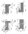
- the part to be equipped 10 comprises a housing 14 for receiving the bearing, this housing being provided with an axial bearing surface 16 surrounded by an annular rim 18 protruding axially, and a recess 20 set back from the axial bearing surface 16.
- the workpiece is fixed to the mandrel 22 by a revolution of geometric axis of rotation 24.
- the bearing 12 is, in this example, consisting of an inner ring 26 and an outer ring 28 on which are formed rolling paths 30, 32 receiving rolling bodies 34 consist of balls.
- the bearing 12 is placed in the housing, so that only the outer ring 28 is in contact with the part 10 at the bearing surface 16.
- a clearance E exists between the bearing and the flange of the housing.
- a tool 36 movable in translation along the axis 36 but fixed in rotation is pressed against the inner ring 26 of the bearing and indirectly puts the outer ring 28 of the bearing bearing against the bearing surface 16.
- the pressure exerted by the tool 36 schematized by the arrow 38 on the figure 1 , is sufficient for the part 10, driven by the mandrel 22, drives the outer ring 28 with it in its rotational movement.
- the bearing pressure must however be sufficiently low to allow a certain freedom of positioning of the outer ring 28 relative to the part 10, in a plane perpendicular to the axis 24 of the mandrel, within the limits of the clearance E with the rim 18.
- the mandrel 22 is rotated, simultaneously driving the workpiece 10 and the outer race 28 of the bearing.
- a rolling wheel 40 then deforms progressively the flange 18 of the piece by folding.
- the movement of the wheel in the radial direction, schematized by the arrow 42 is very progressive, so that the flange being deformed is progressively closer to the outer ring.
- the figure 2 represents a variant that differs from the method previously described essentially in that the deformed element is constituted by the inner ring 26 of a bearing 12.
- This ring 26 comprises a raceway 30 and a flange 18 defining a housing 14 which the bottom constitutes a bearing surface 16 for the part 10 to be equipped.
- a heat treatment prior to the fixing of the elements is necessary so that the piece constituting the ring 26 has a high hardness in the raceway 30 and a good ability to deform at the edge 18.
- Two methods are proposed to obtain its different local properties.
- the element 10 on which the ring 26 is mounted is pressed against the bearing surface 16 by means of a tool 36 which is left to the element 10 rotational mobility around of the axis 24 and in translation in the plane perpendicular to the axis 24.
- the ring 26 is fixed to the mandrel of a lathe and rotated, driving with it the piece 10.
- a rolling wheel is gradually folding the flange 18.
- a centering of the element 10 with respect to the axis 24 occurs when the partially folded flange comes into contact with the element 10, first at a point and then gradually over the entire periphery of the element. element 10.
- the folding is completed when the element 10 is crimped in the housing 14, the flange 18 having taken the position 18A in abutment against the holding surface 44.
- the figure 3 represents another variant in which the deformed element is constituted by an outer ring 28 of rolling, the member to be equipped with this ring being a ring gear 10.
- the outer ring 28 is provided with a surface d support 16 for the ring gear 10 and a flange 18.
- a radial clearance E initially exists between the ring gear 10 and the flange 18.
- An annular tool maintains the ring 10 bears against the bearing surface 16 when setting rotation of the outer ring fixed to the mandrel of a lathe.
- the flange 18 is folded gradually on the ring 10 by a wheel (not shown) whose movement symbolized by the arrow 42 has a radial component directed outwards.
- the progressive folding of the flange allows a centering of the ring relative to the rotation axis 24 of the lathe.
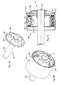
- the pulley 100 mounted by the method according to the invention.
- the pulley comprises a drum 28 constituting the outer ring of a bearing, provided with two raceways 32 housing the balls 34 of the bearing.
- the drum 28 is provided with a transverse bearing surface 16 and a flange 18 projecting from the bearing surface 16.
- the pulley 100 further comprises a shaft 10A on which is fitted a flange 10B provided with its periphery of notches 10C.
- the flange 10B is force-fitted on the axis 10A, so as to form the visible element 10 on the Figure 4A .
- the drum 28 is in turn made by rolling an annealed sheet. Then a localized heat treatment is applied at the level of the raceways 32 to obtain the desired hardness, by introducing residual compression stresses located at the level of the raceways. This localized treatment does not affect the resilience of the rest of the room and in particular the rim 18.
- the periphery of the flange 10B is introduced into the housing circumscribed by the flange 18, bearing against the bearing surface 16, as shown in FIG. Figure 4B .
- the drum 28 is rotated on a lathe (not shown) whose axis of rotation coincides with the axis of rotation of the bearing, and carries with it by friction the subassembly 10 constituted by the flange 10B and the axis 10A.
- the rim 18 is then folded down by means of a rolling wheel or a rivet against the holding surface 44 constituted by the flange 10B, to take the form 10A shown in FIG. figure 4C .
- the subset 10 focuses progressively with respect to the bearing.
- the 10C notches provide better mechanical strength between parts after assembly is complete.
- FIG 5 is schematically illustrated a variant for mounting an inner ring 26 rolling on an element 10 to equip.
- This ring 26 comprises a raceway 30 and a flange 18 delimiting a housing whose bottom constitutes a bearing surface 16 for the element 10 to be equipped.
- the rim 18 is thick so that bending deformation is not possible.
- the flange 18 is then deformed by rotary creep using a rolling tool until the rim takes the form shown at 18A, resting on the holding surface 44.
- the advance of the rolling tool is slow so that the mandrel and the ledge 18 that it drives make several turns - in practice between 5 and 50 turns - before the rim reaches its final position. Under these conditions, the radial force exerted by the wheel remains low.
- a tool advance of 0.05 mm / turn induces radial forces of the order of 400 daN only, to fold the edges in 20 turns.
- the deformed rim is crenellated, to facilitate its folding.
- This variant is applicable in particular to the walls to be deformed which are thick.
Landscapes
- Engineering & Computer Science (AREA)
- General Engineering & Computer Science (AREA)
- Mechanical Engineering (AREA)
- Manufacturing & Machinery (AREA)
- Rolling Contact Bearings (AREA)
- Mounting Of Bearings Or Others (AREA)
- Pens And Brushes (AREA)
Abstract
Description
L'invention est relative à un procédé d'assemblage d'une pièce sur une bague de roulement, et plus particulièrement à un procédé faisant appel à une déformation de la matière périphérique de la bague ou de la pièce.The invention relates to a method of assembling a workpiece on a bearing ring, and more particularly to a process using a deformation of the peripheral material of the ring or the workpiece.
Les bagues de roulement sont des pièces annulaires destinées à être solidarisée à un organe fixe ou rotatif et devant constituer des chemins de roulement pour des corps roulants, tels que des billes, rouleaux ou aiguilles, d'un palier à roulement. Elles doivent donc avoir, au moins au niveau des chemins de roulement, une dureté élevée.The bearing rings are annular pieces intended to be secured to a fixed or rotating member and to form rolling tracks for rolling bodies, such as balls, rollers or needles, of a rolling bearing. They must therefore have, at least at the level of the raceways, a high hardness.
Les bagues de roulement sont généralement fixées à l'organe qu'elles équipent par emmanchement à froid ou à chaud, plus rarement par des éléments de montage tels que des vis. On sait également fixer une bague de roulement à une pièce par déformation d'une partie périphérique de la bague, obtenue par exemple par emboutissage ou poinçonnage. Dans certaines circonstances, notamment lorsque l'épaisseur de matière à déformer devient importante, l'énergie à mettre en oeuvre pour la déformation est importante, et nécessite des presses de grande puissance.The bearing rings are generally attached to the member they fit by cold or hot fitting, more rarely by mounting elements such as screws. It is also known to fix a race to a workpiece by deformation of a peripheral portion of the ring, obtained for example by stamping or punching. In certain circumstances, particularly when the material thickness to be deformed becomes large, the energy to be used for the deformation is important, and requires high-power presses.
Dans le document
Dans le document
Le moyen de mise en place de la bague extérieure du roulement dans son support de manière à ne pas déformer cette bague n'est pas pris en compte.The means for placing the outer ring of the bearing in its support so as not to deform this ring is not taken into account.
L'invention vise donc à remédier aux inconvénients de l'état de la technique, de manière à proposer un procédé permettant d'assembler une bague de roulement à une pièce, avec une très faible dispersion des cotes d'assemblage et une faible puissance.The invention therefore aims to overcome the disadvantages of the state of the art, so as to provide a method for assembling a bearing ring to a workpiece, with a very low dispersion of the assembly dimensions and a low power.
A cet effet, et suivant un premier aspect de l'invention, celle-ci a pour objet un procédé d'assemblage de deux éléments constitués d'une part par une bague de roulement pourvue d'au moins un chemin de roulement et d'autre part par un organe mécanique, le procédé comportant les étapes suivantes :
- un premier des deux éléments est conformé de manière à présenter un rebord annulaire déformable définissant un axe géométrique de référence ;
- l'autre élément est conformé de manière à présenter une surface annulaire de maintien ;
- les deux éléments sont mis en appui l'un contre l'autre, le deuxième élément étant libre de se mouvoir dans un plan transversal par rapport au premier élément et un outil de roulage ayant par rapport au premier élément un mouvement relatif de révolution autour de l'axe géométrique de référence du premier élément vient repousser le rebord pour rabattre radialement le rebord sur la surface de maintien en progressant d'une position de contact initial avec le rebord à une position de contact final avec le rebord en un temps correspondant à au moins cinq révolutions.
- a first of the two elements is shaped so as to have a deformable annular flange defining a reference geometric axis;
- the other element is shaped so as to have an annular holding surface;
- the two elements are placed against one another, the second element being free to move in a plane transverse to the first element and a rolling tool having relative to the first element a relative movement of revolution around the reference geometric axis of the first element pushes the flange to fold the flange radially on the holding surface while progressing from an initial contact position with the flange at a final contact position with the flange in a time corresponding to at least five revolutions.
La déformation progressive du rebord par une avance lente de l'outil de roulage conjuguée à la liberté de mouvement de l'autre élément dans le plan perpendiculaire à l'axe de rotation permet un auto-centrage du deuxième élément par rapport à l'axe de rotation du premier élément. La déformation du rebord peut être orientée radialement vers l'intérieur ou vers l'extérieur.The progressive deformation of the flange by a slow advance of the rolling tool combined with the freedom of movement of the other element in the plane perpendicular to the axis of rotation allows self-centering of the second element with respect to the axis of rotation of the first element. The deformation of the flange may be oriented radially inwards or outwards.
Le mouvement relatif de révolution entre l'outil de roulage et le premier élément peut être réalisé en maintenant le premier élément fixe par rapport à un bâti de machine et en faisant tourner l'outil. Alternativement, et suivant un mode de réalisation préféré, le premier élément est fixé à un mandrin qui est mis en rotation pour entraîner les deux éléments. Avantageusement, l'autre élément est entraîné par friction avec le premier élément. Dans ce cas, le mouvement de l'outil de roulage dans un référentiel fixe par rapport au mandrin peut être un mouvement plan, par exemple un mouvement de translation.The relative movement of revolution between the rolling tool and the first element can be achieved by holding the first fixed element relative to a machine frame and rotating the tool. Alternatively, and in a preferred embodiment, the first member is attached to a mandrel which is rotated to drive the two members. Advantageously, the other element is frictionally driven with the first element. In this case, the movement of the rolling tool in a fixed reference relative to the mandrel may be a plane movement, for example a translational movement.
Suivant un mode de réalisation, l'outil de roulage avance de la position initiale de contact jusqu'à la position finale de contact à une vitesse linéaire correspondant à une progression inférieure à 0,2 mm par tour.According to one embodiment, the rolling tool advances from the initial contact position to the final contact position at a linear speed corresponding to a progression of less than 0.2 mm per revolution.
La vitesse tangentielle de rotation doit être adaptée pour ne pas échauffer le rebord. Dans un exemple de réalisation, le mandrin tourne à une vitesse inférieure à 700 tours par minutes durant l'étape de repoussage.The tangential speed of rotation must be adapted so as not to heat the rim. In an exemplary embodiment, the mandrel rotates at a speed less than 700 rpm during the spinning step.
Suivant une mode de réalisation, le premier élément est la bague. Le procédé peut alors comprendre une étape de recuit de l'ensemble de la bague pour conférer au rebord une ductilité et une résilience permettant son repoussage par l'outil de roulage, l'étape de recuit précédant l'étape de montage sur le tour rotatif. Une étape de traitement thermique ou thermochimique localisé peut être réalisée après l'étape de recuit au niveau du ou des chemins de roulement pour y introduire des contraintes résiduelles de compression localisées et ainsi augmenter la dureté du ou des chemins de roulement. L'étape de traitement thermique ou thermochimique localisé peut être effectuée avant l'étape de montage de la bague sur le tour. On peut également effectuer une trempe globale trempe globale des deux éléments après leur assemblage.According to one embodiment, the first element is the ring. The method may then comprise a step of annealing the entire ring to give the rim a ductility and a resilience allowing its repoussage by the rolling tool, the annealing step preceding the mounting step on the rotary lathe. A localized thermal or thermochemical treatment step may be carried out after the annealing step at the level of the race or races to introduce localized compressive residual stresses and thereby increase the hardness of the raceway (s). The localized thermal or thermochemical treatment step can be performed before the step of mounting the ring on the lathe. It is also possible to carry out a global toughening of the two elements after assembly.
Alternativement il est possible de prévoir une étape de recuit préalable d'une partie seulement de la bague pour conférer au rebord une ductilité et une résilience permettant son repoussage par l'outil de roulage, l'étape de recuit précédant l'étape de montage sur le tour rotatif. L'étape de recuit peut alors être précédée d'une étape de trempe globale de la bague.Alternatively it is possible to provide a preliminary annealing step of only a portion of the ring to give the flange a ductility and resilience allowing its repoussage by the rolling tool, the annealing step preceding the mounting step on the rotating turn. The annealing step can then be preceded by an overall quenching step of the ring.
D'autres traitements localisés des chemins roulements tels que des traitements thermochimiques, par exemple par carbonitruration, sont également possible, le but de ces traitements étant de conférer aux chemins de roulement une structure métallurgique martensitique et une dureté suffisante dans l'application.Other localized treatments of the bearing paths such as thermochemical treatments, for example by carbonitriding, are also possible, the purpose of these treatments being to give the raceways a martensitic metallurgical structure and a sufficient hardness in the application.
Suivant un mode de réalisation, le premier élément est constitué au moins au niveau du rebord par un matériau initialement fritté non fibré, donc ductile, dont les propriétés mécaniques sont ensuite modifiées au cours de l'étape de roulage, notamment par un phénomène de compression qui en augmente la résistance mécanique.According to one embodiment, the first element is constituted at least at the flange by a material initially sintered non-fiber, thus ductile, whose mechanical properties are then modified during the rolling step, in particular by a compression phenomenon which increases the mechanical resistance.
Le procédé est applicable à différents type de bagues et d'organes mécaniques. L'organe mécanique peut ainsi comporter par exemple un arbre s'étendant suivant l'axe de rotation de la bague ou une couronne dentée ou un tambour de poulie. Il est à noter qu'il est applicable notamment à des bagues massives qui ne sont pas en tôle.The method is applicable to different types of rings and mechanical members. The mechanical member may thus comprise for example a shaft extending along the axis of rotation of the ring or a ring gear or a pulley drum. It should be noted that it is applicable in particular to massive rings that are not sheet metal.
Selon un autre mode de réalisation, le deuxième élément est la bague.According to another embodiment, the second element is the ring.
D'autres avantages et caractéristiques ressortiront plus clairement de la description qui va suivre de modes particuliers de réalisation de l'invention, donnés à titre d'exemples non limitatifs, et représentés aux dessins annexés sur lesquels :
- la
figure 1 est un schéma illustrant un procédé de montage selon un premier mode de réalisation de l'invention ; - la
figure 2 illustre un procédé de montage selon un deuxième mode de réalisation de l'invention ; - la
figure 3 illustre un procédé de montage selon un troisième mode de réalisation de l'invention ; - les
figures 4A à 4C illustrent différentes étapes d'un procédé de montage selon un quatrième mode de réalisation de l'invention ; - la
figure 5 illustre un procédé de montage selon un cinquième mode de réalisation de l'invention.
- the
figure 1 is a diagram illustrating a mounting method according to a first embodiment of the invention; - the
figure 2 illustrates a mounting method according to a second embodiment of the invention; - the
figure 3 illustrates a mounting method according to a third embodiment of the invention; - the
Figures 4A to 4C illustrate different steps of a mounting method according to a fourth embodiment of the invention; - the
figure 5 illustrates a mounting method according to a fifth embodiment of the invention.
Pour alléger la présentation, les éléments communs aux différents modes de réalisation seront désignés par les mêmes signes de référence et leur description ne sera pas systématiquement répétée.To simplify the presentation, the elements common to the different embodiments will be designated by the same reference signs and their description will not be systematically repeated.
Sur la
Le mandrin 22 est mis en rotation, entraînant simultanément la pièce 10 et la bague extérieure 28 du roulement. Une molette de roulage 40 vient alors déformer progressivement le rebord 18 de la pièce par pliage. Le mouvement de la molette en direction radiale, schématisé par la flèche 42, est très progressif, de sorte que le rebord en cours de déformation se rapproche progressivement de la bague extérieure. Une fois le contact établi entre le rebord 18 et la bague extérieure en un point de la périphérie de la bague, le roulement 12, qui peut se mouvoir dans le plan perpendiculaire à l'axe de rotation, tend à se repositionner. La rotation de la pièce 10 conjuguée au mouvement radial de la molette 40 favorise alors un auto-centrage du roulement 12 suivant l'axe de rotation 24 du mandrin 22. La position finale 18A du rebord, en appui contre une surface de maintien 44 de la bague extérieure 28, est schématisée sur la
Dans ce mode de réalisation, il est avantageux de maintenir la bague intérieure 26 du roulement fixe en rotation. De cette façon, les billes 34 sont entraînées en rotation par rapport aux deux bagues 26, 28 lors de la déformation du rebord 18 ce qui évite une déformation locale des chemins de roulement au niveau des billes 34.In this embodiment, it is advantageous to maintain the
La
Un traitement thermique préalable à la fixation des éléments est nécessaire pour que la pièce constituant la bague 26 ait une dureté élevée au niveau du chemin de roulement 30 et une bonne capacité à la déformation au niveau du rebord 18. Deux méthodes sont proposées pour obtenir ses propriétés locales différentes.A heat treatment prior to the fixing of the elements is necessary so that the piece constituting the
On peut procéder tout d'abord à une trempe de la bague 26, qui confère à l'ensemble de la bague une dureté élevée, puis effectuer un recuit local au niveau du rebord 18.It is possible first of all to temper the
Alternativement, on peut recuire l'ensemble de la bague 26, puis effectuer un traitement thermique local au niveau du chemin de roulement 30 pour obtenir à ce niveau un changement de phase de l'acier lui conférant la dureté souhaitée.Alternatively, one can anneal the
Dans cet exemple de réalisation, l'élément 10 sur lequel la bague 26 est monté est mis en appui contre la surface d'appui 16 par l'intermédiaire d'un outil 36 qui est laisse à l'élément 10 une mobilité en rotation autour de l'axe 24 et en translation dans le plan perpendiculaire à l'axe 24. La bague 26 est fixée au mandrin d'un tour et mise en rotation, entraînant avec elle la pièce 10. Une molette de roulage vient progressivement replier le rebord 18. Un centrage de l'élément 10 par rapport à l'axe 24 se produit lorsque le rebord partiellement plié entre en contact avec l'élément 10, d'abord en un point puis progressivement sur l'ensemble de la périphérie de l'élément 10. Le pliage s'achève lorsque l'élément 10 se trouve sertie dans le logement 14, le rebord 18 ayant pris la position 18A en appui contre la surface de maintien 44.In this embodiment, the
La
Sur les
Dans une première étape de montage, le flasque 10B est emmanché en force sur l'axe 10A, de manière à former l'élément visible 10 sur la
Le tambour 28 est de son côté réalisé par roulage d'une tôle recuit. Puis un traitement thermique localisé est appliqué au niveau des chemins de roulement 32 pour obtenir la dureté forte recherchée, en introduisant des contraintes résiduelles de compression localisées au niveau des chemins de roulement. Ce traitement localisé ne nuit pas à la résilience du reste de la pièce et notamment du rebord 18.The
La périphérie du flasque 10B est introduite dans le logement circonscrit par le rebord 18, en appui contre la surface d'appui 16, comme illustré sur la
Pour obtenir au niveau du rebord 18 du tambour 28 une résilience importante et au niveau des chemins de roulement 32 une dureté élevée, il est également possible d'effectuer une trempe de la pièce 28, qui lui confère la dureté recherchée au niveau des chemins de roulement, suivie d'un recuit local pour augmenter la résilience du rebord 18.To obtain at the
Sur la
Dans tous les modes de réalisation, l'avance de l'outil de roulage est lente de sorte que le mandrin et le rebord 18 qu'il entraîne font plusieurs tours - en pratique entre 5 et 50 tours - avant que le rebord n'atteigne sa position finale. Dans ces conditions, l'effort radial exercé par la molette reste peu élevé. A titre d'exemple non limitatif, lors du montage d'un galet de poulie du type représenté sur les
L'existence d'un jeu initial E permet un auto-centrage de la pièce sur laquelle le rebord est rabattu. Cet auto-centrage est réalisé par rapport à l'axe de rotation du tour. Il est donc important de bien positionner initialement l'élément pris dans le mandrin, de manière à ce que l'axe de rotation 24 du mandrin soit confondu avec l'axe suivant lequel on souhaite positionner la pièce.The existence of an initial clearance E allows a self-centering of the part on which the flange is folded. This self-centering is performed relative to the rotation axis of the lathe. It is therefore important to properly position the element initially in the mandrel, so that the axis of
De manière caractéristique du procédé, du moins dans les variantes des
Naturellement, diverses modifications sont possibles.Naturally, various modifications are possible.
On peut prévoir que le rebord déformé soit crénelé, pour faciliter son pliage. Cette variante est applicable notamment aux parois à déformer qui sont épaisses.It can be provided that the deformed rim is crenellated, to facilitate its folding. This variant is applicable in particular to the walls to be deformed which are thick.
L'homme du métier saura en outre combiner entre eux les divers mode de réalisation pour constituer d'autres variantes.Those skilled in the art will furthermore be able to combine the various embodiments with one another in order to constitute other variants.
Claims (16)
- A method for assembling two elements composed on the one hand by a rotating ring (26, 28) provided with at least a raceway (30, 32) and on the other hand a mechanical element (10), the method including the following steps:- a first of the two elements is conformed so as to have a deformable annular rim (18) defining a reference geometric axis;- the other element is conformed so as to have a retaining surface (44);- the two elements are resting against each other, the second element being free to move in a transversal plane with respect to the first element, and a curling tool (40) having, with respect to the first element, a relative revolution motion about the reference geometric axis of the first element, spins the rim (18) to radially bend the rim on the retaining surface (44) while progressing from an initial contact position with the rim in a position (18A) of final contact with the rim within a time corresponding to at least five revolutions.
- An assembling method according to claim 1, wherein the first element is fixed to a mandrel (22) which is rotated to drive the two elements about the reference geometric axis of the first element.
- An assembling method according to claim 2, wherein the other element is driven by a friction with the first element.
- A method according to any one of the preceding claims, wherein the curling tool (40) radially progresses from the initial contact position up to the final contact position at a linear speed corresponding to a progression of less than 0.2mm per revolution.
- A method according to any one of the preceding claims, wherein the mandrel (22) rotates at a speed of less than 700 revolutions per minute during the step of spinning.
- A method according to any one of the preceding claims, wherein the first element is the ring (26, 28).
- An assembling method according to claim 6, further including a step of annealing the whole ring (26, 28) to give the rim (18) a ductility and a resilience enabling the deformation thereof by the curling tool (40), with the annealing step preceding the step of mounting on the rotating lathe.
- An assembling method according to claim 7, further including a step of thermal or thermochemical treatment localised on the raceway to introduce compression residual strains localised on the raceway and thus increase the hardness of the raceway, the step of thermal treatment being carried out after the step of annealing.
- A method according to claim 8, wherein the step of localised thermal or thermochemical treatment is carried out prior to the step of mounting the ring on the lathe.
- An assembling method according to claim 6, further including a step of previous annealing of the rim of the ring to give the rim (18) a ductility and a resilience enabling the spinning thereof by the curling tool, with the step of annealing preceding the step of mounting on the rotating lathe.
- A method according to claim 10, further including a step of global quenching of the ring which comes prior to the step of annealing.
- A method according to any one of the preceding claims, further comprising a step of mounting the bearing ring with a second bearing ring, with rolling bodies being interposed between both rings, the mounting of the ring coming prior to the step of spinning the rim of the first part.
- A method according to any one of the preceding claims, characterised in that the deformable rim is made of a non-fibred ductile sintered material which is then compressed by the curling tool.
- An assembly of two elements obtained with a method according to any one of claims 1 to 11, characterised in that the mechanical element (10) includes a shaft (10A) extending along the rotation axis of the ring (26, 28).
- An assembly of two elements obtained with a method according to any one of claims 1 to 11, characterised in that the mechanical member includes a toothed ring.
- An assembly of two elements obtained with a method according to any one of claims 1 to 11, characterised in that the mechanical member includes a pulley roll.
Applications Claiming Priority (1)
| Application Number | Priority Date | Filing Date | Title |
|---|---|---|---|
| FR0610770A FR2909738B1 (en) | 2006-12-11 | 2006-12-11 | METHOD FOR ASSEMBLING A BEARING RING WITH A MECHANICAL MEMBER |
Publications (2)
| Publication Number | Publication Date |
|---|---|
| EP1935528A1 EP1935528A1 (en) | 2008-06-25 |
| EP1935528B1 true EP1935528B1 (en) | 2010-07-07 |
Family
ID=38169587
Family Applications (1)
| Application Number | Title | Priority Date | Filing Date |
|---|---|---|---|
| EP07291454A Active EP1935528B1 (en) | 2006-12-11 | 2007-12-05 | Method for assembling a bearing ring with a mechanical element |
Country Status (4)
| Country | Link |
|---|---|
| EP (1) | EP1935528B1 (en) |
| AT (1) | ATE473063T1 (en) |
| DE (1) | DE602007007562D1 (en) |
| FR (1) | FR2909738B1 (en) |
Families Citing this family (2)
| Publication number | Priority date | Publication date | Assignee | Title |
|---|---|---|---|---|
| WO2011091853A1 (en) * | 2010-01-29 | 2011-08-04 | Aktiebolaget Skf | Rolling bearing and method for manufacturing the same |
| FR2967465B1 (en) | 2010-11-16 | 2012-12-21 | Ntn Snr Roulements | DEBRAYABLE MECHANISM FOR DRIVING BETWEEN A BELT AND A TURNOVER |
Family Cites Families (7)
| Publication number | Priority date | Publication date | Assignee | Title |
|---|---|---|---|---|
| JPS61175318A (en) * | 1985-01-24 | 1986-08-07 | レツクスノルド インコーポレーテツド | Selectively cured bearing which can be caulked |
| IT1285306B1 (en) * | 1996-03-08 | 1998-06-03 | Skf Ind Spa | METHOD OF MOUNTING THE BEARING OF A MOTOR VEHICLE WHEEL HUB ON THE RELEVANT POST AND BEARING-POST SYSTEM |
| IT1288795B1 (en) * | 1996-10-31 | 1998-09-24 | Skf Ind Spa | BEARING GROUP FOR VEHICLE WHEEL HUB SUITABLE FOR CONNECTION WITH THE BRAKING PART FOR COLD FORMING. |
| ITTO20010604A1 (en) | 2001-06-22 | 2002-12-22 | Sistemi Sospensioni Spa | ASSEMBLING THE BEARING FOR A WHEEL HUB ON A SUSPENSION OF A VEHICLE. |
| DE10163234A1 (en) * | 2001-12-21 | 2003-07-10 | Bosch Gmbh Robert | End shield for an electrical machine and electrical machine |
| DE20304989U1 (en) * | 2003-03-26 | 2004-08-05 | Ab Skf | Bearing mounting fixes has inner seating for bearing and outer seating for component which consist of cylindrical tubular sections whose wall thickness is less than radial spacing between two seatings |
| DE102004055204A1 (en) * | 2004-11-16 | 2006-05-18 | Fag Kugelfischer Ag & Co. Ohg | Unit of a wheel bearing and at least one fixed vehicle carrier |
-
2006
- 2006-12-11 FR FR0610770A patent/FR2909738B1/en not_active Expired - Fee Related
-
2007
- 2007-12-05 AT AT07291454T patent/ATE473063T1/en not_active IP Right Cessation
- 2007-12-05 EP EP07291454A patent/EP1935528B1/en active Active
- 2007-12-05 DE DE602007007562T patent/DE602007007562D1/en active Active
Also Published As
| Publication number | Publication date |
|---|---|
| DE602007007562D1 (en) | 2010-08-19 |
| FR2909738B1 (en) | 2009-02-20 |
| ATE473063T1 (en) | 2010-07-15 |
| FR2909738A1 (en) | 2008-06-13 |
| EP1935528A1 (en) | 2008-06-25 |
Similar Documents
| Publication | Publication Date | Title |
|---|---|---|
| EP0475792B1 (en) | Process for making a collar of a roller bearing, and roller bearing equipped with such a collar | |
| EP2981371B1 (en) | Method for manufacturing a tubular metal part | |
| EP2110570B1 (en) | Method of manufacturing a bearing device | |
| FR2632695A1 (en) | CLUTCH DISC FOR A FRICTION CLUTCH | |
| EP1935528B1 (en) | Method for assembling a bearing ring with a mechanical element | |
| EP1865206A2 (en) | Belt transmission mechanism | |
| FR3013087A1 (en) | MECHANICAL BEARING | |
| FR3052104A1 (en) | MOTOR VEHICLE WHEEL ASSEMBLY | |
| WO2007017579A1 (en) | Production of a metal part by means of hot pressing and part thus obtained | |
| EP2017491A1 (en) | Manufacturing method and mechanically strengthened self-aligning washer | |
| CN102549301B (en) | Drive belt provided with a laminated set of steel rings | |
| FR2767080A1 (en) | Electromagnetic clutch manufacture | |
| EP3670014A1 (en) | Method for straightening a shaft by applying a radial variable strain hardening force on the shaft in rotation | |
| FR2918425A1 (en) | ROLLING STOP DEVICE | |
| FR2978219A1 (en) | MOUNTING A ROTATING SHAFT IN A HOUSING THROUGH A BEARING | |
| EP1473534A1 (en) | Roll and drive assembly for its rotation | |
| JP2015028372A (en) | Rolling bearing unit for supporting wheel | |
| WO2007077375A1 (en) | Multiple clutch assembly particularly for a motor vehicle | |
| FR2931090A1 (en) | Bearing integrated assembly powering method for vehicle, involves maintaining free end of canon in axial support against inner ring of bearing, and axial-stretching fibers of revolution wall of canon to realize powering of assembly | |
| EP1771587A2 (en) | Method for producing a shaft pertaining to a starter | |
| FR3079895A1 (en) | Clutch disc having a damping cage, an intermediate member and a cut hub flange, and a method of manufacturing a clutch disc | |
| JP2005088668A (en) | Rolling bearing unit for supporting wheel, and method for manufacturing the same | |
| FR2780117A1 (en) | Roller bearing for steering column of vehicle | |
| CH703961A2 (en) | Method for assembling hard piece e.g. anchor, on axle in horlogical applications, involves compressing ring between axle and piece without being in contact with piece so as to generate friction between ring and washer | |
| FR3057625B1 (en) | LAUNCHER FOR MOTOR VEHICLE STARTER WITH THERMAL MOTOR |
Legal Events
| Date | Code | Title | Description |
|---|---|---|---|
| PUAI | Public reference made under article 153(3) epc to a published international application that has entered the european phase |
Free format text: ORIGINAL CODE: 0009012 |
|
| AK | Designated contracting states |
Kind code of ref document: A1 Designated state(s): AT BE BG CH CY CZ DE DK EE ES FI FR GB GR HU IE IS IT LI LT LU LV MC MT NL PL PT RO SE SI SK TR |
|
| AX | Request for extension of the european patent |
Extension state: AL BA HR MK RS |
|
| 17P | Request for examination filed |
Effective date: 20081112 |
|
| AKX | Designation fees paid |
Designated state(s): AT BE BG CH CY CZ DE DK EE ES FI FR GB GR HU IE IS IT LI LT LU LV MC MT NL PL PT RO SE SI SK TR |
|
| GRAP | Despatch of communication of intention to grant a patent |
Free format text: ORIGINAL CODE: EPIDOSNIGR1 |
|
| GRAL | Information related to payment of fee for publishing/printing deleted |
Free format text: ORIGINAL CODE: EPIDOSDIGR3 |
|
| GRAS | Grant fee paid |
Free format text: ORIGINAL CODE: EPIDOSNIGR3 |
|
| GRAS | Grant fee paid |
Free format text: ORIGINAL CODE: EPIDOSNIGR3 |
|
| GRAA | (expected) grant |
Free format text: ORIGINAL CODE: 0009210 |
|
| AK | Designated contracting states |
Kind code of ref document: B1 Designated state(s): AT BE BG CH CY CZ DE DK EE ES FI FR GB GR HU IE IS IT LI LT LU LV MC MT NL PL PT RO SE SI SK TR |
|
| REG | Reference to a national code |
Ref country code: GB Ref legal event code: FG4D Free format text: NOT ENGLISH |
|
| REG | Reference to a national code |
Ref country code: CH Ref legal event code: EP |
|
| REG | Reference to a national code |
Ref country code: IE Ref legal event code: FG4D |
|
| REF | Corresponds to: |
Ref document number: 602007007562 Country of ref document: DE Date of ref document: 20100819 Kind code of ref document: P |
|
| REG | Reference to a national code |
Ref country code: NL Ref legal event code: VDEP Effective date: 20100707 |
|
| PG25 | Lapsed in a contracting state [announced via postgrant information from national office to epo] |
Ref country code: SI Free format text: LAPSE BECAUSE OF FAILURE TO SUBMIT A TRANSLATION OF THE DESCRIPTION OR TO PAY THE FEE WITHIN THE PRESCRIBED TIME-LIMIT Effective date: 20100707 |
|
| LTIE | Lt: invalidation of european patent or patent extension |
Effective date: 20100707 |
|
| PG25 | Lapsed in a contracting state [announced via postgrant information from national office to epo] |
Ref country code: AT Free format text: LAPSE BECAUSE OF FAILURE TO SUBMIT A TRANSLATION OF THE DESCRIPTION OR TO PAY THE FEE WITHIN THE PRESCRIBED TIME-LIMIT Effective date: 20100707 Ref country code: NL Free format text: LAPSE BECAUSE OF FAILURE TO SUBMIT A TRANSLATION OF THE DESCRIPTION OR TO PAY THE FEE WITHIN THE PRESCRIBED TIME-LIMIT Effective date: 20100707 Ref country code: LT Free format text: LAPSE BECAUSE OF FAILURE TO SUBMIT A TRANSLATION OF THE DESCRIPTION OR TO PAY THE FEE WITHIN THE PRESCRIBED TIME-LIMIT Effective date: 20100707 Ref country code: FI Free format text: LAPSE BECAUSE OF FAILURE TO SUBMIT A TRANSLATION OF THE DESCRIPTION OR TO PAY THE FEE WITHIN THE PRESCRIBED TIME-LIMIT Effective date: 20100707 |
|
| REG | Reference to a national code |
Ref country code: IE Ref legal event code: FD4D |
|
| PG25 | Lapsed in a contracting state [announced via postgrant information from national office to epo] |
Ref country code: BG Free format text: LAPSE BECAUSE OF FAILURE TO SUBMIT A TRANSLATION OF THE DESCRIPTION OR TO PAY THE FEE WITHIN THE PRESCRIBED TIME-LIMIT Effective date: 20101007 Ref country code: PT Free format text: LAPSE BECAUSE OF FAILURE TO SUBMIT A TRANSLATION OF THE DESCRIPTION OR TO PAY THE FEE WITHIN THE PRESCRIBED TIME-LIMIT Effective date: 20101108 Ref country code: PL Free format text: LAPSE BECAUSE OF FAILURE TO SUBMIT A TRANSLATION OF THE DESCRIPTION OR TO PAY THE FEE WITHIN THE PRESCRIBED TIME-LIMIT Effective date: 20100707 Ref country code: IS Free format text: LAPSE BECAUSE OF FAILURE TO SUBMIT A TRANSLATION OF THE DESCRIPTION OR TO PAY THE FEE WITHIN THE PRESCRIBED TIME-LIMIT Effective date: 20101107 Ref country code: CY Free format text: LAPSE BECAUSE OF FAILURE TO SUBMIT A TRANSLATION OF THE DESCRIPTION OR TO PAY THE FEE WITHIN THE PRESCRIBED TIME-LIMIT Effective date: 20100707 |
|
| PG25 | Lapsed in a contracting state [announced via postgrant information from national office to epo] |
Ref country code: LV Free format text: LAPSE BECAUSE OF FAILURE TO SUBMIT A TRANSLATION OF THE DESCRIPTION OR TO PAY THE FEE WITHIN THE PRESCRIBED TIME-LIMIT Effective date: 20100707 Ref country code: GR Free format text: LAPSE BECAUSE OF FAILURE TO SUBMIT A TRANSLATION OF THE DESCRIPTION OR TO PAY THE FEE WITHIN THE PRESCRIBED TIME-LIMIT Effective date: 20101008 Ref country code: SE Free format text: LAPSE BECAUSE OF FAILURE TO SUBMIT A TRANSLATION OF THE DESCRIPTION OR TO PAY THE FEE WITHIN THE PRESCRIBED TIME-LIMIT Effective date: 20100707 |
|
| PG25 | Lapsed in a contracting state [announced via postgrant information from national office to epo] |
Ref country code: DK Free format text: LAPSE BECAUSE OF FAILURE TO SUBMIT A TRANSLATION OF THE DESCRIPTION OR TO PAY THE FEE WITHIN THE PRESCRIBED TIME-LIMIT Effective date: 20100707 Ref country code: IE Free format text: LAPSE BECAUSE OF FAILURE TO SUBMIT A TRANSLATION OF THE DESCRIPTION OR TO PAY THE FEE WITHIN THE PRESCRIBED TIME-LIMIT Effective date: 20100707 |
|
| PLBE | No opposition filed within time limit |
Free format text: ORIGINAL CODE: 0009261 |
|
| STAA | Information on the status of an ep patent application or granted ep patent |
Free format text: STATUS: NO OPPOSITION FILED WITHIN TIME LIMIT |
|
| PG25 | Lapsed in a contracting state [announced via postgrant information from national office to epo] |
Ref country code: IT Free format text: LAPSE BECAUSE OF FAILURE TO SUBMIT A TRANSLATION OF THE DESCRIPTION OR TO PAY THE FEE WITHIN THE PRESCRIBED TIME-LIMIT Effective date: 20100707 Ref country code: CZ Free format text: LAPSE BECAUSE OF FAILURE TO SUBMIT A TRANSLATION OF THE DESCRIPTION OR TO PAY THE FEE WITHIN THE PRESCRIBED TIME-LIMIT Effective date: 20100707 Ref country code: SK Free format text: LAPSE BECAUSE OF FAILURE TO SUBMIT A TRANSLATION OF THE DESCRIPTION OR TO PAY THE FEE WITHIN THE PRESCRIBED TIME-LIMIT Effective date: 20100707 Ref country code: EE Free format text: LAPSE BECAUSE OF FAILURE TO SUBMIT A TRANSLATION OF THE DESCRIPTION OR TO PAY THE FEE WITHIN THE PRESCRIBED TIME-LIMIT Effective date: 20100707 Ref country code: RO Free format text: LAPSE BECAUSE OF FAILURE TO SUBMIT A TRANSLATION OF THE DESCRIPTION OR TO PAY THE FEE WITHIN THE PRESCRIBED TIME-LIMIT Effective date: 20100707 |
|
| 26N | No opposition filed |
Effective date: 20110408 |
|
| BERE | Be: lapsed |
Owner name: S.N.R. ROULEMENTS Effective date: 20101231 |
|
| PG25 | Lapsed in a contracting state [announced via postgrant information from national office to epo] |
Ref country code: ES Free format text: LAPSE BECAUSE OF FAILURE TO SUBMIT A TRANSLATION OF THE DESCRIPTION OR TO PAY THE FEE WITHIN THE PRESCRIBED TIME-LIMIT Effective date: 20101018 |
|
| REG | Reference to a national code |
Ref country code: DE Ref legal event code: R097 Ref document number: 602007007562 Country of ref document: DE Effective date: 20110408 |
|
| PG25 | Lapsed in a contracting state [announced via postgrant information from national office to epo] |
Ref country code: MC Free format text: LAPSE BECAUSE OF NON-PAYMENT OF DUE FEES Effective date: 20101231 |
|
| PG25 | Lapsed in a contracting state [announced via postgrant information from national office to epo] |
Ref country code: BE Free format text: LAPSE BECAUSE OF NON-PAYMENT OF DUE FEES Effective date: 20101231 |
|
| PG25 | Lapsed in a contracting state [announced via postgrant information from national office to epo] |
Ref country code: MT Free format text: LAPSE BECAUSE OF FAILURE TO SUBMIT A TRANSLATION OF THE DESCRIPTION OR TO PAY THE FEE WITHIN THE PRESCRIBED TIME-LIMIT Effective date: 20100707 |
|
| REG | Reference to a national code |
Ref country code: CH Ref legal event code: PL |
|
| GBPC | Gb: european patent ceased through non-payment of renewal fee |
Effective date: 20111205 |
|
| PG25 | Lapsed in a contracting state [announced via postgrant information from national office to epo] |
Ref country code: HU Free format text: LAPSE BECAUSE OF FAILURE TO SUBMIT A TRANSLATION OF THE DESCRIPTION OR TO PAY THE FEE WITHIN THE PRESCRIBED TIME-LIMIT Effective date: 20110108 Ref country code: LU Free format text: LAPSE BECAUSE OF NON-PAYMENT OF DUE FEES Effective date: 20101205 |
|
| PG25 | Lapsed in a contracting state [announced via postgrant information from national office to epo] |
Ref country code: TR Free format text: LAPSE BECAUSE OF FAILURE TO SUBMIT A TRANSLATION OF THE DESCRIPTION OR TO PAY THE FEE WITHIN THE PRESCRIBED TIME-LIMIT Effective date: 20100707 Ref country code: LI Free format text: LAPSE BECAUSE OF NON-PAYMENT OF DUE FEES Effective date: 20111231 Ref country code: CH Free format text: LAPSE BECAUSE OF NON-PAYMENT OF DUE FEES Effective date: 20111231 Ref country code: GB Free format text: LAPSE BECAUSE OF NON-PAYMENT OF DUE FEES Effective date: 20111205 |
|
| REG | Reference to a national code |
Ref country code: FR Ref legal event code: PLFP Year of fee payment: 9 |
|
| REG | Reference to a national code |
Ref country code: FR Ref legal event code: PLFP Year of fee payment: 10 |
|
| REG | Reference to a national code |
Ref country code: FR Ref legal event code: PLFP Year of fee payment: 11 |
|
| PGFP | Annual fee paid to national office [announced via postgrant information from national office to epo] |
Ref country code: DE Payment date: 20221213 Year of fee payment: 16 |
|
| PGFP | Annual fee paid to national office [announced via postgrant information from national office to epo] |
Ref country code: FR Payment date: 20231221 Year of fee payment: 17 |
|
| REG | Reference to a national code |
Ref country code: DE Ref legal event code: R119 Ref document number: 602007007562 Country of ref document: DE |
|
| PG25 | Lapsed in a contracting state [announced via postgrant information from national office to epo] |
Ref country code: DE Free format text: LAPSE BECAUSE OF NON-PAYMENT OF DUE FEES Effective date: 20240702 |