EP1934436B1 - Schaltschlepphebelanordnung - Google Patents
Schaltschlepphebelanordnung Download PDFInfo
- Publication number
- EP1934436B1 EP1934436B1 EP06814888A EP06814888A EP1934436B1 EP 1934436 B1 EP1934436 B1 EP 1934436B1 EP 06814888 A EP06814888 A EP 06814888A EP 06814888 A EP06814888 A EP 06814888A EP 1934436 B1 EP1934436 B1 EP 1934436B1
- Authority
- EP
- European Patent Office
- Prior art keywords
- follower
- lateral
- lobe
- finger
- assembly
- Prior art date
- Legal status (The legal status is an assumption and is not a legal conclusion. Google has not performed a legal analysis and makes no representation as to the accuracy of the status listed.)
- Not-in-force
Links
Images


Classifications
-
- F—MECHANICAL ENGINEERING; LIGHTING; HEATING; WEAPONS; BLASTING
- F01—MACHINES OR ENGINES IN GENERAL; ENGINE PLANTS IN GENERAL; STEAM ENGINES
- F01L—CYCLICALLY OPERATING VALVES FOR MACHINES OR ENGINES
- F01L13/00—Modifications of valve-gear to facilitate reversing, braking, starting, changing compression ratio, or other specific operations
- F01L13/0015—Modifications of valve-gear to facilitate reversing, braking, starting, changing compression ratio, or other specific operations for optimising engine performances by modifying valve lift according to various working parameters, e.g. rotational speed, load, torque
- F01L13/0036—Modifications of valve-gear to facilitate reversing, braking, starting, changing compression ratio, or other specific operations for optimising engine performances by modifying valve lift according to various working parameters, e.g. rotational speed, load, torque the valves being driven by two or more cams with different shape, size or timing or a single cam profiled in axial and radial direction
-
- F—MECHANICAL ENGINEERING; LIGHTING; HEATING; WEAPONS; BLASTING
- F01—MACHINES OR ENGINES IN GENERAL; ENGINE PLANTS IN GENERAL; STEAM ENGINES
- F01L—CYCLICALLY OPERATING VALVES FOR MACHINES OR ENGINES
- F01L1/00—Valve-gear or valve arrangements, e.g. lift-valve gear
- F01L1/12—Transmitting gear between valve drive and valve
- F01L1/18—Rocking arms or levers
- F01L1/185—Overhead end-pivot rocking arms
-
- F—MECHANICAL ENGINEERING; LIGHTING; HEATING; WEAPONS; BLASTING
- F01—MACHINES OR ENGINES IN GENERAL; ENGINE PLANTS IN GENERAL; STEAM ENGINES
- F01L—CYCLICALLY OPERATING VALVES FOR MACHINES OR ENGINES
- F01L13/00—Modifications of valve-gear to facilitate reversing, braking, starting, changing compression ratio, or other specific operations
- F01L13/0005—Deactivating valves
-
- F—MECHANICAL ENGINEERING; LIGHTING; HEATING; WEAPONS; BLASTING
- F01—MACHINES OR ENGINES IN GENERAL; ENGINE PLANTS IN GENERAL; STEAM ENGINES
- F01L—CYCLICALLY OPERATING VALVES FOR MACHINES OR ENGINES
- F01L2305/00—Valve arrangements comprising rollers
Definitions
- the present invention relates to mechanisms for altering the actuation of valves in internal combustion engines, and more particularly to finger follower type rocker arms for changing between high and low valve lifts.
- VVA Variable valve activation
- One approach is to provide an intermediary cam follower arrangement which is rotatable about the engine camshaft and is capable of changing both the valve lift and timing.
- the camshaft typically includes both high-lift and low-lift lobes for each such valve.
- Such an arrangement can be complicated and costly to manufacture and difficult to install during engine assembly.
- HLA hydraulic lash adjuster
- Still another known approach is to provide a deactivation mechanism in the valve-actuating end of a rocker arm cam follower (opposite from the HLA pivot end) which locks and unlocks the valve actuator portion from the follower body. Unlike the HLA deactivation approach, this approach typically requires both high-lift and low-lift cam lobes to provide variable lift.
- a rocker arm cam follower with a finger body having a first cam follower positioned within the finger body and a secondary cam follower.
- the first cam follower is selectively moveable relative to the finger body and in other designs the secondary cam followers are selectively moveable relative to the finger body.
- the moveable members generally are axially moveable or pivot about a secondary axis which adds complexity to the design or fails to provide smooth motion.
- the invention provides a finger follower assembly for variably activating a valve of an internal combustion engine having a camshaft with at least one lobe
- the finger follower assembly comprising: a follower body having a first end portion configured to couple to the engine, a second end portion configured to couple to the valve of the engine, and an aperture formed in the follower body between the first and second end portions; a shaft coupled to the follower body that transverses the aperture; a cam follower supported at least partially within the aperture by the shaft and configured for engagement with the at least one lobe, the cam follower configured to pilot on the camshaft to maintain an alignment of the cam follower with respect to the at least one lobe; and a latching mechanism for selectively latching and unlatching the cam follower to the follower body to provide a first valve lift capability and a second valve lift capability; wherein the cam follower is movable within the aperture in a direction parallel to a longitudinal axis of the shaft, and wherein the cam follower defines a body portion located
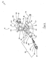
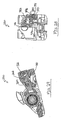
- Fig. 1 is a perspective view of a camshaft and a finger follower assembly embodying the present invention.
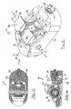
- Fig. 2 is an exploded view of the finger follower assembly of Fig. 1 .
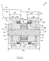
- Fig. 3 is a cross section view of the finger follower assembly of Fig. 1 taken along lines 3-3 of Fig. 14 .
- Fig. 4 is a cross section view of the finger follower assembly of Fig. 1 taken along lines 4-4 of Fig. 14 illustrating a piston of the finger follower assembly in a retracted position.
- Figs. 5-6 are perspective views of a lateral cam follower of the finger follower assembly of Fig. 1 .
- Fig. 7 is an end view of the lateral cam follower of Fig. 5 .
- Fig. 8 is a side view of the lateral cam follower of Fig. 5 .
- Fig. 9 is a cross section view of the finger follower assembly of Fig. 1 taken along lines 9-9 of Fig. 14 illustrating the piston between the retracted position and an extended position.
- Fig. 10 is a perspective view of a latching mechanism of the finger follower assembly of Fig. 1 illustrating the piston in the retracted position.
- Fig. 11 is a bottom view of the latching mechanism of Fig. 10 .
- Fig. 12 is a perspective view of the latching mechanism of Fig. 10 illustrating the piston in the extended position.
- Fig. 13 is a bottom view of the latching mechanism of Fig. 12 .
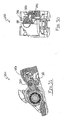
- Fig. 14 is a perspective view of the finger follower assembly of Fig. 1 illustrating the piston in the retracted position.
- Fig. 15 is a cross section view of the finger follower assembly of Fig. 14 taken along lines 15-15 of Fig. 14 .
- Fig. 16 is a cross section view of the finger follower assembly of Fig. 14 taken along lines 16-16 of Fig. 14 .
- Fig. 17 is a perspective view of the finger follower assembly of Fig. 1 illustrating the piston in the extended position.
- Fig. 18 is a cross section view of the finger follower assembly of Fig. 17 taken along lines 18-18 of Fig. 17 .
- Fig. 19 is a cross section view of the finger follower assembly of Fig. 17 taken along lines 19-19 of Fig. 17 .
- Fig. 20 is a perspective view of the finger follower assembly of Fig. 1 illustrating the piston in the extended position and the lateral cam follower in a downward position.
- Fig. 21 is a cross section view of the finger follower assembly of Fig. 20 taken along lines 21-21 of Fig. 20 .
- Fig. 22 is a cross section view of the finger follower assembly of Fig. 20 taken along lines 22-22 of Fig. 20 .
- Fig. 23 is a perspective view of an alternative construction of the finger follower assembly of Fig. 1 .
- Figs. 24-33 are cross section views of the finger follower assembly of Fig. 23 taken along lines 23-23 through 33-33 respectively, of Fig. 23 .
- Fig. 1 illustrates a finger follower rocker assembly 30 for use with an internal combustion engine having a camshaft assembly 32.
- the camshaft assembly 32 includes a camshaft 34 that rotates about an axis 36.
- the illustrated camshaft assembly 32 includes a plurality of cam assemblies 38 that are coupled to the camshaft 34 for rotation with the camshaft 34.
- Each of the cam assemblies 38 includes a central cam lobe 40, a first lateral cam lobe 42 and a second lateral cam lobe 44.
- the first and second lateral lobes 42 and 44 are adjacent the central lobe 40.
- Each of the cam lobes 40, 42, 44 includes a perimeter surface 46 and side walls 48 that are generally normal to the perimeter surface 46.
- the central cam lobe 40 has a larger profile or outer dimension than the lateral cam lobes 42 and 44 such that the central cam lobe 40 includes side wall portions 48 that extend beyond the perimeter surfaces 46 of the lateral cam lobes 42 and 44.
- the internal combustion engine further includes a lash adjuster 50 and an engine valve 52.
- the finger follower assembly 30 includes a follower body 54, a follower assembly 56, and a latching mechanism 58.
- the follower body 54 includes a first end portion 60 and a second end portion 62.
- the first end portion 60 includes a concave socket 64 and a bore 66.
- the concave socket 64 couples to an engine through the lash adjuster 50 ( Fig. 1 ).
- the bore 66 partially receives the latching mechanism 58.
- the illustrated bore 66 is generally cylindrical and defines an inner dimension D1 that is generally constant.
- the second end portion 62 is coupled to the valve 52 ( Fig. 1 ).
- the follower body 54 further includes opposed side walls 68 that extend between the end portions 60, 62.
- the illustrated side walls 68 partially define an aperture 70 between the first and second end portions 60, 62.
- the side walls 68 include an inner surface 72 that defines an inner width W1 of the aperture 70 and an outer surface 74 that defines an outer width W2 of the follower body 54.
- the side walls 68 each further include an aperture 76.
- the apertures 76 of the side walls 68 are aligned such that apertures 76 receive a shaft 78 having a shaft axis 79.
- the follower assembly 56 includes a lateral cam follower 80 and a central cam follower 82.
- the central cam follower 82 includes an inner cylindrical race 84 and an outer cylindrical race 86 with rolling elements 88 positioned therebetween such that the outer cylindrical race 86 is rotatable about the shaft axis 79.
- the inner cylindrical race 84 is coupled to the shaft 78 using a loose fit such that the inner cylindrical race 84 is movable along the shaft axis 79 and around the shaft axis 79, the purpose of which will be discussed below.
- the lateral follower 80 has a body portion 90 with a through bore 92 that receives the shaft 78 to couple the lateral follower 80 to the follower body 54.
- the lateral follower 80 pivots or rotates about the shaft 78 and is movable along the shaft 78 in a direction parallel to the shaft axis 79.
- the body portion 90 of the lateral follower 80 further includes an actuator receiving aperture 94.
- the actuator receiving aperture 94 is partially defined by a downwardly facing surface 96.
- the downwardly facing surface 96 of the lateral follower 80 is at least partially convex (e.g., radiused, logarithmic profile, etc.) such that the surface 96 defines a crowned profile when viewed in the cross section illustrated in Fig. 9 , the purpose of which will be discussed below.
- the body portion 90 of the lateral follower 80 defines a width W3 that is less than the inner width W1 of the aperture 70 such that there are gaps 98 between the inner surfaces 72 of the follower body walls 68 and the body portion 90 of the lateral follower 80. While Fig. 3 illustrates the gaps 98 with a substantially equal length L1, the follower body 90 is movable in a direction parallel to the shaft axis 79 such that the length L1 of the gaps 98 can vary.
- the lateral follower 80 further includes first and second contact portions 100, 102 that extend upwardly from the body portion 90 to define a gap 104 therebetween.
- the contact portions 100, 102 each include a convex contact surface 106, 108 respectively, having a width W4, W5, respectively.
- the widths W4 and W5 both are approximately 8.25 mm. In other constructions, the widths W4 and W5 can be greater than or less than 8.25 mm.
- a ratio of the total width of the contact surfaces 106 and 108 (W4 + W5) to the outer width W2 of the follower body 54 is approximately 70%. In other constructions the ratio can be greater or less than 70%.
- the first and second contact portions 100 and 102 further define lateral contact portions 110 and 112, respectively.
- the lateral contact portions 110 and 112 are generally normal to the convex contact surfaces 106 and 108, respectively, and the lateral contact portions 110 and 112 partially define the gap 104 between the contact portions 100 and 102.
- the body portion 90 of the lateral follower 80 further defines a generally centrally located slot 114 that receives and retains the central follower 82 partially within the body portion 90 of the lateral follower 80.
- the illustrated lateral follower 80 is integrally formed as a single piece, such as by casting, molding, machining and the like.
- the lateral follower 80 can be a two-piece design, such that the first and second contact portions are separate components.
- the contact portions can be interconnected by a member such that the contact portions are coupled for co-rotation about the shaft 78 and movement along the shaft axis 79.
- the central lobe 40 of the cam assembly 38 is received in the gap 104 between the first and second contact portions 100 and 102 of the lateral follower 80.
- the central lobe 40 is captured between the contact portions 100 and 102 of the lateral follower 80.
- the side wall portions 48 of the central lobe 40 are available to pilot the lateral contact portions 110 and 112 of the lateral follower 80 at all rotational positions of the lateral follower 80 and the camshaft 34.
- the location of the cam assembly 38 can vary along the camshaft axis 36.
- the central lobe 40 can contact either of the lateral contact surfaces 110 or 112 of the lateral follower 80 to move the lateral follower 80 relative to the valve 52 and within the follower body 54 to maintain proper relative position of the lateral follower contact surfaces 106 and 108 with respect to the lateral lobes 42 and 44.
- the gaps 98 between the follower body 54 and the lateral follower body 90 allow the lateral follower 80 to move in a direction parallel to the shaft axis 79 along the shaft 78.
- the lateral follower 80 is one piece, the entire lateral follower 80 will move in a direction parallel to axis 79 along the shaft 78.
- the central follower 82 which is retained in the slot 114 of the lateral follower 80, will move in a direction parallel the shaft axis 79 with the lateral follower 80. Therefore, the central follower 82 maintains proper alignment with the central lobe 40. Such movement of the central follower 82 is facilitated by the loose fit of the inner race 84 of the central follower 82 on the shaft 78.
- the lateral follower 80 pilots in this manner on the central lobe 40, the lateral follower 80 and central follower 82 remain aligned with the cam assembly 38 regardless of the manufacturing variations or thermal variations that may change the position of the cam assembly 38.
- Such a feature allows the widths W4 and W5 of the contact surfaces 106 and 108 to be maximized such that the widths W4 and W5 of the contact surfaces 106 and 108 are generally equal to the width of the perimeter surfaces 46 of the lateral lobes 42 and 44, respectively, and the contact surfaces 106 and 108 generally contact the lateral lobes 42 and 44, respectively, along their entire width W4 and W5.
- the lateral follower 80 can move along the shaft 78 in response to a change in position of the cam assembly 38, the lateral lobes 40 and 42 and both of the contact surfaces 106 and 108 remain aligned to facilitate contact along substantially the entire width of the contact surfaces 106 and 108.
- a biasing member 116 is coupled to the follower body 54 and the lateral follower 80 such that the biasing member 116 biases the lateral follower 80 about the axis 79 of the shaft 78 upwardly in the direction of arrow 117 ( Fig. 14 ).
- the biasing member 116 is a torsion spring. In other constructions, the biasing member can take other suitable forms.
- the illustrated latching mechanism 58 includes a piston 120, a biasing member 122, a shaft 124, and an end cap or base 126.
- the piston 120 is a generally cylindrical member that includes a blind bore 128. As illustrated, the portion of the piston 120 received in the bore 66 has a generally constant outer dimension.
- the piston 120 further includes a locking projection 130 that extends from an end of the piston 120.
- the locking projection 130 includes an upwardly facing surface 132 and a downwardly facing surface 134. As best seen in Fig. 9 , the upwardly facing surface 132 of the locking projection 130 is generally planar.
- the illustrated piston 120 further includes vent apertures 136 that extend through the piston 120 and provide fluid communication between piston bore 128 and the exterior of the finger follower assembly 30.
- the piston 120 further includes a slot 138 that provides fluid communication between the concave socket 64 and the bore 128 of the piston 120.
- the slot 138 receives a tang or tab 140 that extends from the base 126.
- the base 126 is generally fixed with respect to the follower body 54 and the tang 140 engages the slot 138 to limit the amount of rotational movement of the piston 120 about the shaft 124.
- there is a gap 142 or clearance between the tang 140 and the piston 120 to provide only a limited amount of rotational movement of the piston 120 with respect to the base 126 and follower body 54.
- the gap 142 allows the piston 120 to rotate in order to align the upwardly facing surface 132 of the piston 120 and the downwardly facing surface 96 of the lateral follower 80 when the surfaces 132 and 96 engage such that the surfaces 132 and 96 are generally parallel ( Fig. 23 ).
- the slot 138 restricts rotation of the piston 120 in order to ensure that the locking projection 130 can be received in the aperture 94 of the lateral follower 80.
- the shaft 124 includes a first end portion 148 and a second end portion 150.
- the second end portion 150 includes a recess 152 that receives a clip 154 to couple the base 126 to the shaft 124.
- the first end portion 148 includes an enlarged end portion or shoulder 156 that acts as a stop for the biasing member 122.
- the illustrated biasing member 122 is a tapered coil spring.
- the biasing member 122 includes a first end 157a and a second end 157b and the biasing member 122 is tapered such that the outer dimension of the coil spring is smaller at the first end 157a and larger at the second end 157b.
- the first end 157a of the biasing member 122 acts against the enlarged end portion 156 of the shaft 124 and the second end 157b of the biasing member 122 acts against a washer member 158 that is between the second end 157b of the biasing member 122 and a clip 160 that is received in a recess 162 formed in the piston 120.
- the biasing member 122 biases the piston 120 toward the retracted or unlatched position shown in Fig. 16 .
- the illustrated latching mechanism 58 is a generally fully self contained latching mechanism that is received in the bore 66 formed in the first end portion 60 of the follower body 54.
- the illustrated latching mechanism 58 has a relatively low mass moment of inertia because of the compact nature of the latching member 58.
- the low mass moment of inertia of the finger follower 30 is also facilitated by the latch mechanism 58 being located relatively close to spherical socket 64, which is the location where the finger follower 30 pivots.
- the biasing member 116 of the lateral follower 80 is able to contact the engagement portion 130 of the piston 120. Therefore, regardless of the axial location of the lateral follower 80 with respect to the shaft 78 or whether the piston 120 is in the retracted or extended position, the biasing member 116 does not block the piston 120 from moving into to the aperture 94 of the lateral follower 80.
- the camshaft 34 rotates about the camshaft axis 36 and oil is supplied from a pressurized source to the finger follower assembly 30 through the lash adjuster 50.
- the oil supplied to the finger follower 30 is at a relatively low pressure. Therefore, the biasing member 122, which has a natural tendency to expand in the illustrated construction, retains the piston 120 in the unlatched or retracted position ( Figs. 15-17 ).
- the high lift or lateral lobes 42 and 44 will contact surfaces 106 and 108 of the lateral follower 80 and cause a pivoting force on the lateral follower 80.
- the lateral follower 80 simply pivots about the shaft axis 79 without imparting any significant force on the finger body 54.
- the lateral follower 80 is biased toward the lateral lobes 42 and 44 by the biasing member 116 and therefore the contact surfaces 106 and 108 generally remain in contact with the lateral lobes 42 and 44.
- the central or low lift lobe 40 contacts the central follower 82 to cause the outer race 86 to rotate about the shaft 78.
- the lift of the valve 52 is controlled by the low lift lobe 40 through the central follower 82.
- the loose fit of the inner race 84 on the shaft 78 enables relative rotational and axial movement of the inner race 84 with respect to the shaft 78.
- Relative rotational motion of the inner race 84 with respect to the shaft 78 allows the inner race 84 to precess with respect to the shaft 78. Precessing of the inner race 84 extends the life of the central follower 82 because the number of fatigue cycles at any given portion of the inner race 84 is reduced.
- Fig. 9 illustrates the piston 120 in a partially extended position.
- the tapered biasing member 122 facilitates travel of the oil, generally indicated by the arrows 170, around the biasing member 122 in order to allow the pressurized oil to extend the piston 120.
- the locking projection 130 of the piston 120 extends into the aperture 94 of the lateral follower 80 thereby interconnecting the lateral follower 80 and the follower body 54.
- the finger follower assembly 30 pivots on the lash adjuster 50 to provide relatively high lift of the engine valve 52.
- a limited amount of oil is allowed to escape from the bore 126 of the piston 120 through the vent apertures 136 to provide lubrication for the lateral follower 80, the central follower 82, and the cams 40, 42, and 44.
- the convex curvature of the downwardly facing surface 96 minimizes the stress concentrations created between the engagement surfaces 96, 132 when the lateral follower 80 is forced into contact with the piston 120, regardless of manufacturing variation that would cause the surfaces 96, 132 to contact in slightly different orientations.
- Figs. 23-33 illustrate an alternative construction of the finger follower assembly 30 of Figs. 1-22 .
- the finger follower assembly 230 of Figs. 23-32 is substantially the same as the finger follower assembly 30 of Fig. 1-22 and like components have been given like reference numbers plus 200 and only the general differences will be discussed below.
- the illustrated latching mechanism 258 is of a slightly different construction from the latching mechanism 58 described above.
- the biasing member 322 is of a different configuration having a generally cylindrical coil diameter instead of the tapered diameter of the biasing member 122. Additionally, hooked ends 322a and 322b engage respective pins 379a and 379b that are coupled to the end cap 326 and the piston 320, respectively.
- the finger follower assembly 230 includes a fluid venting system 380.
- the fluid venting system 380 includes a vent passageway 382, a secondary passageway 384, and a tertiary passageway 386 formed in the follower body 254.
- vent passageway 382 is in fluid communication with a fluid chamber 381 defined by the end cap or base 326, the bore 328 of the piston 320, and the bore 266 of the follower body 254 depending on the location of the piston 320.
- a plug 388 is located within the vent passageway 382 to substantially prevent fluid communication through the vent passageway 382 past the plug 388.
- the secondary passageway 384 is adjacent the vent passageway 382. As best seen in Fig. 27 , the secondary passageway 384 extends to the concave socket 264 such that the secondary passageway 384 is in fluid communication with the source of pressurized fluid supplied from the lash adjuster 50 of Fig. 1 .
- a vent piston 390 is located within the secondary passageway 384.
- the vent piston 390 is biased in the direction of the arrow 392 by a biasing member 394 that acts against a plug 396.
- the tertiary passageway 386 is generally normal to the vent passageway 382 and the secondary passageway 384.
- the tertiary passageway 386 provides fluid communication between the vent passageway 382, the secondary passageway 384, and the outside of the finger follower 230.
- Figs. 26 and 27 illustrate the piston 320 in the recessed or unlatched position such that the finger follower 230 is operating in the low valve lift mode of operation. As best seen in Fig. 26 , the oil pressure is insufficient to move the vent piston 390 against the bias of the biasing member 394.
- the piston 320 begins to extend from the bore 266.
- the increased oil flow and pressure generally indicated by the arrow 395, moves the vent piston 390 against the force of the biasing member 394 until the vent piston 390 contacts the plug 388.
- air or fluid between the plug 396 and the vent piston 390 is allowed to escape through an aperture 397 defined by the plug 396.
- fluid communication is inhibited through the vent passageway 382 and the secondary passageway 384 due to the blockage created by the vent piston 390.
- the piston 320 when the piston 320 moves to the fully extended position (i.e., high valve lift mode), the piston 320 uncovers the vent passageway 382 and oil flows into the vent passageway 382, generally indicated by the arrow 398.
- the vent piston 390 substantially prevents escape of oil from the vent passageway 382 through the tertiary passageway 386. Therefore, adequate oil pressure is maintained within the fluid chamber 381 to maintain the piston 320 in the extended or latched position, which allows the finger follower assembly 230 to operate the engine valve 52 ( Fig. 1 ) in the high lift mode.
- oil is allowed to escape from the fluid chamber 381 through the vent apertures 336 to provide lubrication to the lateral follower 280, central follower 282, and the cam lobes.
- the oil is supplied by the lash adjuster 50 ( Fig. 1 ) at a sufficient quantity and pressure such that the oil that escapes through the vent apertures 336 does not substantially reduce the oil pressure in the fluid chamber 381 such that the piston biasing member 322 retracts the piston 320.
- vent apertures 336 can be eliminated and the finger follower assembly and cam assembly can be lubricated using oil from other passageways created in the finger follower assembly.
Landscapes
- Engineering & Computer Science (AREA)
- Mechanical Engineering (AREA)
- General Engineering & Computer Science (AREA)
- Valve-Gear Or Valve Arrangements (AREA)
- Valve Device For Special Equipments (AREA)
Claims (7)
- Schlepphebelanordnung (30) für ein variables Aktivieren eines Ventils (52) eines Verbrennungsmotors mit einer Nockenwelle (34) mit mindestens einem Nocken (40, 42, 44), wobei die Schlepphebelanordnung (30) folgende Merkmale aufweist:- einen Folgerkörper (54) mit einem ersten Endabschnitt (60), der dafür ausgelegt ist, mit dem Motor zu koppeln, einem zweiten Endabschnitt (62), der dafür ausgelegt ist, mit dem Ventil (52) des Motors zu koppeln, und mit einer Öffnung (70), die in dem Folgerkörper (54) zwischen den ersten und zweiten Endabschnitten (60, 62) gebildet ist;- eine mit dem Folgerkörper (54) gekoppelte Welle (78), die durch die Öffnung (70) hindurch verläuft;- einen Schlepphebel (80, 82), der von der Welle (78) mindestens teilweise innerhalb der Öffnung (70) gehalten ist und der für einen Eingriff mit dem mindestens einen Nocken (40, 42, 44) ausgelegt ist, wobei der Schlepphebel (80, 82) dafür ausgelegt ist, an der Nockenwelle (34) geführt zu werden, um eine Ausrichtung des Schlepphebels (80, 82) in Bezug zu dem mindestens einen Nocken (40, 42, 44) aufrechtzuerhalten; und- einen Verriegelungsmechanismus (58) für ein selektives Verriegeln und Entriegeln des Schlepphebels (80, 82) mit dem Folgerkörper (54), um eine erste Ventilhubfähigkeit und eine zweite Ventilhubfähigkeit zu bewerkstelligen;- wobei der Schlepphebel (80, 82) innerhalb der Öffnung (70) in einer Richtung parallel zu einer Längsachse (79) der Welle (78) bewegbar ist, und wobei der Schlepphebel (80, 82) einen Körperabschnitt definiert, der mindestens teilweise innerhalb der Öffnung (70) angeordnet ist, wobei der Körperabschnitt eine Breite aufweist, die kleiner ist als eine Breite der Öffnung (70), so dass sich der Schlepphebel (80, 82) in Bezug zu dem Folgerkörper (54) bewegen kann;dadurch gekennzeichnet, dass der Schlepphebel ein seitlicher Folger (80) ist, der dafür ausgelegt ist, an dem zentralen Nocken (40) der Nockenwelle (34) geführt zu werden, die einen zentralen Nocken (40) und einen seitlichen Nocken (42, 44) neben einer Seite des zentralen Nockens (40) aufweist, wobei die Schlepphebelanordnung (30) darüber hinaus einen zentralen Folger (82) aufweist, der für einen Eingriff mit dem zentralen Nocken (40) ausgelegt ist, wobei der zentrale Nocken (40) eine Umfangsoberfläche (46) aufweist, die im Gebrauch den zentralen Folger (82) kontaktiert, sowie einen Seitenwandabschnitt (48), der im Gebrauch an dem seitlichen Folger (80) angreift, um den seitlichen Folger (80) an der Nockenwelle (34) zu führen.
- Schlepphebelanordnung nach Anspruch 1, wobei der zentrale Folger (82) durch die Welle (78) drehbar mindestens teilweise innerhalb der Öffnung (70) gehalten ist.
- Schlepphebelanordnung nach Anspruch 1 oder 2, wobei der zentrale Folger (82) mit dem seitlichen Folger (80) derart gekoppelt ist, dass eine Bewegung des seitlichen Folgers (80) in Bezug zu dem Ventil (52) eine Bewegung des zentralen Folgers (82) bewirkt.
- Schlepphebelanordnung nach einem der Ansprüche 1 bis 3, wobei der seitliche Folger (80) eine erste Kontaktfläche (106, 108) aufweist, die dafür ausgelegt ist, den seitlichen Nocken (42, 44) zu ergreifen, sowie eine zweite Kontaktfläche (110, 112), die im Wesentlichen senkrecht zu der ersten Kontaktfläche (106, 108) angeordnet und dafür ausgelegt ist, den Seitenwandabschnitt (48) des zentralen Nockens (40) zu ergreifen.
- Schlepphebelanordnung nach einem der vorhergehenden Ansprüche, wobei der Verriegelungsmechanismus (58) ein Verriegelungsglied aufweist, das eine Eingriffsfläche aufweist, wobei das Verriegelungsglied selektiv den Schlepphebel (80) mit dem Folgerkörper (54) verbindet, und wobei der Schlepphebel (80) eine Eingriffsfläche (96) aufweist, die mindestens teilweise eine Öffnung definiert, die den Verriegelungsmechanismus (58) aufnimmt, und wobei mindestens eine der Eingriffsflächen mindestens teilweise konvex ist.
- Schlepphebelanordnung nach Anspruch 5, wobei die Eingriffsfläche (96) des Schlepphebels (80) mindestens teilweise konvex ist.
- Schlepphebelanordnung nach einem der vorhergehenden Ansprüche, wobei der Schlepphebel (80, 82) einstückig als eine einzige Komponente ausgebildet ist.
Priority Applications (2)
| Application Number | Priority Date | Filing Date | Title |
|---|---|---|---|
| EP10186111A EP2305966A1 (de) | 2005-09-16 | 2006-09-18 | Schaltschlepphebelanordnung |
| EP10186083A EP2317084A1 (de) | 2005-09-16 | 2006-09-18 | Schaltschlepphebelanordnung |
Applications Claiming Priority (2)
| Application Number | Priority Date | Filing Date | Title |
|---|---|---|---|
| US71812005P | 2005-09-16 | 2005-09-16 | |
| PCT/US2006/036349 WO2007035673A2 (en) | 2005-09-16 | 2006-09-18 | Switching finger follower assembly |
Related Child Applications (2)
| Application Number | Title | Priority Date | Filing Date |
|---|---|---|---|
| EP10186111.0 Division-Into | 2010-10-01 | ||
| EP10186083.1 Division-Into | 2010-10-01 |
Publications (2)
| Publication Number | Publication Date |
|---|---|
| EP1934436A2 EP1934436A2 (de) | 2008-06-25 |
| EP1934436B1 true EP1934436B1 (de) | 2011-09-14 |
Family
ID=37667157
Family Applications (3)
| Application Number | Title | Priority Date | Filing Date |
|---|---|---|---|
| EP06814888A Not-in-force EP1934436B1 (de) | 2005-09-16 | 2006-09-18 | Schaltschlepphebelanordnung |
| EP10186111A Withdrawn EP2305966A1 (de) | 2005-09-16 | 2006-09-18 | Schaltschlepphebelanordnung |
| EP10186083A Withdrawn EP2317084A1 (de) | 2005-09-16 | 2006-09-18 | Schaltschlepphebelanordnung |
Family Applications After (2)
| Application Number | Title | Priority Date | Filing Date |
|---|---|---|---|
| EP10186111A Withdrawn EP2305966A1 (de) | 2005-09-16 | 2006-09-18 | Schaltschlepphebelanordnung |
| EP10186083A Withdrawn EP2317084A1 (de) | 2005-09-16 | 2006-09-18 | Schaltschlepphebelanordnung |
Country Status (5)
| Country | Link |
|---|---|
| US (1) | US20080245330A1 (de) |
| EP (3) | EP1934436B1 (de) |
| JP (1) | JP2009509081A (de) |
| AT (1) | ATE524638T1 (de) |
| WO (1) | WO2007035673A2 (de) |
Families Citing this family (16)
| Publication number | Priority date | Publication date | Assignee | Title |
|---|---|---|---|---|
| DE102006013566A1 (de) * | 2006-03-24 | 2007-09-27 | Schaeffler Kg | Schaltbarer Schlepphebel |
| US20080283003A1 (en) | 2007-05-16 | 2008-11-20 | Hendriksma Nick J | Two-step roller finger cam follower |
| US9228454B2 (en) | 2010-03-19 | 2016-01-05 | Eaton Coporation | Systems, methods and devices for rocker arm position sensing |
| US20190309663A9 (en) | 2008-07-22 | 2019-10-10 | Eaton Corporation | Development of a switching roller finger follower for cylinder deactivation in internal combustion engines |
| US8215275B2 (en) | 2010-08-13 | 2012-07-10 | Eaton Corporation | Single lobe deactivating rocker arm |
| US8245680B2 (en) * | 2010-03-03 | 2012-08-21 | GM Global Technology Operations LLC | Engine including valve lift mechanism with stress reduction features |
| WO2011116331A2 (en) * | 2010-03-19 | 2011-09-22 | Eaton Corporation | Switching rocker arm |
| US8584630B2 (en) * | 2010-03-30 | 2013-11-19 | Schaeffler Technologies AG & Co. KG | Switchable roller finger follower assembly |
| US8627796B2 (en) | 2011-04-21 | 2014-01-14 | Eaton Corporation | Pivot foot for deactivating rocker arm |
| JP6184417B2 (ja) * | 2011-11-06 | 2017-08-23 | イートン コーポレーションEaton Corporation | ラッチピンアセンブリ |
| SE537693C2 (sv) * | 2013-03-11 | 2015-09-29 | Scania Cv Ab | Kamföljare för en ventillyftanordning i en förbränningsmotor |
| KR101545399B1 (ko) | 2013-11-18 | 2015-08-18 | 영신정공 주식회사 | 등급화된 랫칭피스톤을 갖는 실린더 휴지기구 |
| CN107743541B (zh) | 2015-04-17 | 2020-05-12 | 伊顿智能动力有限公司 | 摇臂弹簧保持器 |
| USD791190S1 (en) | 2015-07-13 | 2017-07-04 | Eaton Corporation | Rocker arm assembly |
| USD833482S1 (en) | 2015-07-13 | 2018-11-13 | Eaton Corporation | Rocker arm |
| DE102018114572A1 (de) * | 2017-06-20 | 2018-12-20 | Eaton Intelligent Power Limited | Exzentrischer riegel von schaltrollenkipphebel |
Family Cites Families (34)
| Publication number | Priority date | Publication date | Assignee | Title |
|---|---|---|---|---|
| DE2753197A1 (de) * | 1976-12-15 | 1978-06-22 | Eaton Corp | Ventilsteuervorrichtung |
| US4739675A (en) * | 1980-11-14 | 1988-04-26 | Connell Calvin C | Cylindrical tappet |
| JPS60159318A (ja) * | 1984-01-27 | 1985-08-20 | Kawasaki Heavy Ind Ltd | ピボツト式ロツカア−ムの脱落防止装置 |
| US4607600A (en) * | 1984-12-25 | 1986-08-26 | Toyota Jidosha Kabushiki Kaisha | Valve actuating apparatus in internal combustion engine |
| US4768467A (en) * | 1986-01-23 | 1988-09-06 | Fuji Jukogyo Kabushiki Kaisha | Valve operating system for an automotive engine |
| EP0620360A3 (de) * | 1990-02-16 | 1995-01-18 | Lotus Group Ltd | Ventilstösselanordnung. |
| DE4404145A1 (de) * | 1994-02-09 | 1995-08-10 | Schaeffler Waelzlager Kg | Schalteinrichtung in einem Ventiltrieb |
| DE19606796A1 (de) * | 1995-05-05 | 1996-11-07 | Audi Ag | Vorrichtung zum Koppeln eines auf einer Achse gelagerten Hebels |
| US5529033A (en) * | 1995-05-26 | 1996-06-25 | Eaton Corporation | Multiple rocker arm valve control system |
| US5655488A (en) * | 1996-07-22 | 1997-08-12 | Eaton Corporation | Dual event valve control system |
| US6439179B2 (en) * | 2000-01-14 | 2002-08-27 | Delphi Technologies, Inc. | Deactivation and two-step roller finger follower having a bracket and lost motion spring |
| EP1149988B1 (de) * | 2000-04-26 | 2005-11-02 | Delphi Technologies, Inc. | Verfahren und Vorrichtung für einen zweistufigen Nockenprofilwechsel |
| US6314928B1 (en) * | 2000-12-06 | 2001-11-13 | Ford Global Technologies, Inc. | Rocker arm assembly |
| US6467445B1 (en) * | 2001-10-03 | 2002-10-22 | Delphi Technologies, Inc. | Deactivation and two-step roller finger follower having a slider bracket |
| US6591798B2 (en) * | 2001-12-17 | 2003-07-15 | Delphi Technologies, Inc. | Variable valve actuation assembly for an internal combustion engine |
| US6532920B1 (en) * | 2002-02-08 | 2003-03-18 | Ford Global Technologies, Inc. | Multipositional lift rocker arm assembly |
| US6755167B2 (en) * | 2002-02-26 | 2004-06-29 | Delphi Technologies, Inc. | Two-step roller finger cam follower having spool-shaped low-lift roller |
| US6615782B1 (en) * | 2002-04-12 | 2003-09-09 | Delphi Technologies, Inc. | Two-step finger follower rocker arm |
| US6691657B2 (en) * | 2002-04-12 | 2004-02-17 | Delphi Technologies, Inc. | Two-step finger follower rocker arm |
| US6668775B2 (en) * | 2002-04-12 | 2003-12-30 | Delphi Technologies, Inc. | Lock-pin cartridge for a two-step finger follower rocker arm |
| US6997152B2 (en) * | 2002-04-29 | 2006-02-14 | Delphi Technologies, Inc. | Lock-pin cartridge for a valve deactivation rocker arm assembly |
| US6668779B2 (en) * | 2002-05-08 | 2003-12-30 | Delphi Technologies, Inc. | Two-step finger follower rocker arm assembly |
| DE10220904B4 (de) * | 2002-05-10 | 2005-04-07 | Meta Motoren- Und Energie-Technik Gmbh | Vorrichtung zum Verstellen des Hubs eines von einer Nockenwelle betätigten Ventils |
| US6745734B2 (en) * | 2002-05-24 | 2004-06-08 | Delphi Technologies, Inc. | Variable valve actuating mechanism having torsional lash control spring |
| DE10226821A1 (de) * | 2002-06-15 | 2003-12-24 | Ina Schaeffler Kg | Schlepphebel eines Ventiltriebs einer Brennkraftmaschine |
| DE10230108B4 (de) * | 2002-07-04 | 2004-06-24 | Meta Motoren- Und Energie-Technik Gmbh | Vorrichtung zum Verstellen des Hubs eines von einer Nockenwelle betätigten Ventils |
| US6810844B2 (en) * | 2002-12-10 | 2004-11-02 | Delphi Technologies, Inc. | Method for 3-step variable valve actuation |
| DE10310220A1 (de) * | 2003-03-08 | 2004-09-16 | Daimlerchrysler Ag | Vorrichtung zur Koppelung bzw. Entkoppelung zweier Betätigungshebel eines Ventiltriebes einer Brennkraftmaschine und Verfahren hierzu |
| DE10318295A1 (de) * | 2003-04-23 | 2004-11-11 | Ina-Schaeffler Kg | Schlepphebel eines Ventiltriebs einer Brennkraftmaschine |
| DE10345307A1 (de) * | 2003-09-30 | 2005-04-14 | Ina-Schaeffler Kg | Schlepphebel eines Ventiltriebs einer Brennkraftmaschine |
| US7093572B2 (en) * | 2003-12-19 | 2006-08-22 | Delphi Technologies, Inc. | Roller finger follower assembly for valve deactivation |
| DE102004005594A1 (de) * | 2004-02-04 | 2005-08-25 | Fev Motorentechnik Gmbh | Schlepphebel zur Hubumschaltung |
| WO2005093224A1 (en) * | 2004-03-03 | 2005-10-06 | Timken Us Corporation | Switching finger follower assembly |
| US6925978B1 (en) * | 2004-08-24 | 2005-08-09 | Delphi Technologies, Inc. | Two-step roller finger cam follower having angled lock pin |
-
2006
- 2006-09-18 EP EP06814888A patent/EP1934436B1/de not_active Not-in-force
- 2006-09-18 JP JP2008531420A patent/JP2009509081A/ja active Pending
- 2006-09-18 US US12/065,954 patent/US20080245330A1/en not_active Abandoned
- 2006-09-18 EP EP10186111A patent/EP2305966A1/de not_active Withdrawn
- 2006-09-18 WO PCT/US2006/036349 patent/WO2007035673A2/en active Application Filing
- 2006-09-18 AT AT06814888T patent/ATE524638T1/de not_active IP Right Cessation
- 2006-09-18 EP EP10186083A patent/EP2317084A1/de not_active Withdrawn
Also Published As
| Publication number | Publication date |
|---|---|
| ATE524638T1 (de) | 2011-09-15 |
| EP2305966A1 (de) | 2011-04-06 |
| EP1934436A2 (de) | 2008-06-25 |
| US20080245330A1 (en) | 2008-10-09 |
| EP2317084A1 (de) | 2011-05-04 |
| JP2009509081A (ja) | 2009-03-05 |
| WO2007035673A3 (en) | 2007-05-24 |
| WO2007035673A2 (en) | 2007-03-29 |
Similar Documents
| Publication | Publication Date | Title |
|---|---|---|
| EP1934436B1 (de) | Schaltschlepphebelanordnung | |
| US6997152B2 (en) | Lock-pin cartridge for a valve deactivation rocker arm assembly | |
| US6691657B2 (en) | Two-step finger follower rocker arm | |
| US6615782B1 (en) | Two-step finger follower rocker arm | |
| EP1367228B1 (de) | Kipphebel zur zweistufigen Nockenbetätigung | |
| US6668775B2 (en) | Lock-pin cartridge for a two-step finger follower rocker arm | |
| EP1725744B1 (de) | Schaltschlepphebelanordnung | |
| CN107355275B (zh) | 包括摇臂的配气机构总成 | |
| US6837197B2 (en) | Dual valve lift and valve deactivation | |
| CA1329524C (en) | Rocker arm with cam-contacting roller | |
| US6966291B1 (en) | Latch timing mechanism for a two-step roller finger cam follower | |
| US6925978B1 (en) | Two-step roller finger cam follower having angled lock pin | |
| US20080283003A1 (en) | Two-step roller finger cam follower | |
| US7093572B2 (en) | Roller finger follower assembly for valve deactivation | |
| CN114080492B (zh) | 金属冲压切换滚轮指状随动件 | |
| US6412460B1 (en) | Valve operating system in internal combustion engine | |
| CN115667676A (zh) | 摇臂 | |
| US6640759B1 (en) | Two-step finger follower rocker arm | |
| EP1013898B1 (de) | Ventilsteuerungseinrichtung für eine Brennkraftmaschine | |
| US20240125253A1 (en) | Valve actuation system comprising a discrete lost motion device | |
| JP3320046B2 (ja) | 内燃機関の動弁装置 |
Legal Events
| Date | Code | Title | Description |
|---|---|---|---|
| PUAI | Public reference made under article 153(3) epc to a published international application that has entered the european phase |
Free format text: ORIGINAL CODE: 0009012 |
|
| 17P | Request for examination filed |
Effective date: 20080314 |
|
| AK | Designated contracting states |
Kind code of ref document: A2 Designated state(s): AT BE BG CH CY CZ DE DK EE ES FI FR GB GR HU IE IS IT LI LT LU LV MC NL PL PT RO SE SI SK TR |
|
| 17Q | First examination report despatched |
Effective date: 20080923 |
|
| RAP1 | Party data changed (applicant data changed or rights of an application transferred) |
Owner name: TIMKEN US LLC |
|
| RAP1 | Party data changed (applicant data changed or rights of an application transferred) |
Owner name: KOYO BEARINGS USA LLC |
|
| GRAP | Despatch of communication of intention to grant a patent |
Free format text: ORIGINAL CODE: EPIDOSNIGR1 |
|
| DAX | Request for extension of the european patent (deleted) | ||
| GRAS | Grant fee paid |
Free format text: ORIGINAL CODE: EPIDOSNIGR3 |
|
| GRAA | (expected) grant |
Free format text: ORIGINAL CODE: 0009210 |
|
| AK | Designated contracting states |
Kind code of ref document: B1 Designated state(s): AT BE BG CH CY CZ DE DK EE ES FI FR GB GR HU IE IS IT LI LT LU LV MC NL PL PT RO SE SI SK TR |
|
| REG | Reference to a national code |
Ref country code: GB Ref legal event code: FG4D |
|
| REG | Reference to a national code |
Ref country code: CH Ref legal event code: EP |
|
| REG | Reference to a national code |
Ref country code: IE Ref legal event code: FG4D |
|
| REG | Reference to a national code |
Ref country code: DE Ref legal event code: R231 Ref document number: 602006024449 Country of ref document: DE |
|
| REG | Reference to a national code |
Ref country code: DE Ref legal event code: R096 Ref document number: 602006024449 Country of ref document: DE Effective date: 20111208 |
|
| REG | Reference to a national code |
Ref country code: NL Ref legal event code: VDEP Effective date: 20110914 |
|
| PG25 | Lapsed in a contracting state [announced via postgrant information from national office to epo] |
Ref country code: LT Free format text: LAPSE BECAUSE OF FAILURE TO SUBMIT A TRANSLATION OF THE DESCRIPTION OR TO PAY THE FEE WITHIN THE PRESCRIBED TIME-LIMIT Effective date: 20110914 Ref country code: FI Free format text: LAPSE BECAUSE OF FAILURE TO SUBMIT A TRANSLATION OF THE DESCRIPTION OR TO PAY THE FEE WITHIN THE PRESCRIBED TIME-LIMIT Effective date: 20110914 Ref country code: DE Free format text: LAPSE BECAUSE OF THE APPLICANT RENOUNCES Effective date: 20111103 Ref country code: SE Free format text: LAPSE BECAUSE OF FAILURE TO SUBMIT A TRANSLATION OF THE DESCRIPTION OR TO PAY THE FEE WITHIN THE PRESCRIBED TIME-LIMIT Effective date: 20110914 |
|
| LTIE | Lt: invalidation of european patent or patent extension |
Effective date: 20110914 |
|
| PG25 | Lapsed in a contracting state [announced via postgrant information from national office to epo] |
Ref country code: LV Free format text: LAPSE BECAUSE OF FAILURE TO SUBMIT A TRANSLATION OF THE DESCRIPTION OR TO PAY THE FEE WITHIN THE PRESCRIBED TIME-LIMIT Effective date: 20110914 Ref country code: SI Free format text: LAPSE BECAUSE OF FAILURE TO SUBMIT A TRANSLATION OF THE DESCRIPTION OR TO PAY THE FEE WITHIN THE PRESCRIBED TIME-LIMIT Effective date: 20110914 Ref country code: AT Free format text: LAPSE BECAUSE OF FAILURE TO SUBMIT A TRANSLATION OF THE DESCRIPTION OR TO PAY THE FEE WITHIN THE PRESCRIBED TIME-LIMIT Effective date: 20110914 Ref country code: GR Free format text: LAPSE BECAUSE OF FAILURE TO SUBMIT A TRANSLATION OF THE DESCRIPTION OR TO PAY THE FEE WITHIN THE PRESCRIBED TIME-LIMIT Effective date: 20111215 Ref country code: CY Free format text: LAPSE BECAUSE OF FAILURE TO SUBMIT A TRANSLATION OF THE DESCRIPTION OR TO PAY THE FEE WITHIN THE PRESCRIBED TIME-LIMIT Effective date: 20110914 |
|
| REG | Reference to a national code |
Ref country code: AT Ref legal event code: MK05 Ref document number: 524638 Country of ref document: AT Kind code of ref document: T Effective date: 20110914 |
|
| PG25 | Lapsed in a contracting state [announced via postgrant information from national office to epo] |
Ref country code: BE Free format text: LAPSE BECAUSE OF FAILURE TO SUBMIT A TRANSLATION OF THE DESCRIPTION OR TO PAY THE FEE WITHIN THE PRESCRIBED TIME-LIMIT Effective date: 20110914 |
|
| PG25 | Lapsed in a contracting state [announced via postgrant information from national office to epo] |
Ref country code: MC Free format text: LAPSE BECAUSE OF NON-PAYMENT OF DUE FEES Effective date: 20110930 Ref country code: SK Free format text: LAPSE BECAUSE OF FAILURE TO SUBMIT A TRANSLATION OF THE DESCRIPTION OR TO PAY THE FEE WITHIN THE PRESCRIBED TIME-LIMIT Effective date: 20110914 Ref country code: IS Free format text: LAPSE BECAUSE OF FAILURE TO SUBMIT A TRANSLATION OF THE DESCRIPTION OR TO PAY THE FEE WITHIN THE PRESCRIBED TIME-LIMIT Effective date: 20120114 Ref country code: CZ Free format text: LAPSE BECAUSE OF FAILURE TO SUBMIT A TRANSLATION OF THE DESCRIPTION OR TO PAY THE FEE WITHIN THE PRESCRIBED TIME-LIMIT Effective date: 20110914 |
|
| REG | Reference to a national code |
Ref country code: CH Ref legal event code: PL |
|
| PG25 | Lapsed in a contracting state [announced via postgrant information from national office to epo] |
Ref country code: IT Free format text: LAPSE BECAUSE OF FAILURE TO SUBMIT A TRANSLATION OF THE DESCRIPTION OR TO PAY THE FEE WITHIN THE PRESCRIBED TIME-LIMIT Effective date: 20110914 Ref country code: PT Free format text: LAPSE BECAUSE OF FAILURE TO SUBMIT A TRANSLATION OF THE DESCRIPTION OR TO PAY THE FEE WITHIN THE PRESCRIBED TIME-LIMIT Effective date: 20120116 Ref country code: RO Free format text: LAPSE BECAUSE OF FAILURE TO SUBMIT A TRANSLATION OF THE DESCRIPTION OR TO PAY THE FEE WITHIN THE PRESCRIBED TIME-LIMIT Effective date: 20110914 Ref country code: PL Free format text: LAPSE BECAUSE OF FAILURE TO SUBMIT A TRANSLATION OF THE DESCRIPTION OR TO PAY THE FEE WITHIN THE PRESCRIBED TIME-LIMIT Effective date: 20110914 Ref country code: EE Free format text: LAPSE BECAUSE OF FAILURE TO SUBMIT A TRANSLATION OF THE DESCRIPTION OR TO PAY THE FEE WITHIN THE PRESCRIBED TIME-LIMIT Effective date: 20110914 Ref country code: NL Free format text: LAPSE BECAUSE OF FAILURE TO SUBMIT A TRANSLATION OF THE DESCRIPTION OR TO PAY THE FEE WITHIN THE PRESCRIBED TIME-LIMIT Effective date: 20110914 |
|
| REG | Reference to a national code |
Ref country code: IE Ref legal event code: MM4A |
|
| PLBE | No opposition filed within time limit |
Free format text: ORIGINAL CODE: 0009261 |
|
| STAA | Information on the status of an ep patent application or granted ep patent |
Free format text: STATUS: NO OPPOSITION FILED WITHIN TIME LIMIT |
|
| PG25 | Lapsed in a contracting state [announced via postgrant information from national office to epo] |
Ref country code: CH Free format text: LAPSE BECAUSE OF NON-PAYMENT OF DUE FEES Effective date: 20110930 Ref country code: IE Free format text: LAPSE BECAUSE OF NON-PAYMENT OF DUE FEES Effective date: 20110918 Ref country code: LI Free format text: LAPSE BECAUSE OF NON-PAYMENT OF DUE FEES Effective date: 20110930 Ref country code: DK Free format text: LAPSE BECAUSE OF FAILURE TO SUBMIT A TRANSLATION OF THE DESCRIPTION OR TO PAY THE FEE WITHIN THE PRESCRIBED TIME-LIMIT Effective date: 20110914 |
|
| REG | Reference to a national code |
Ref country code: FR Ref legal event code: ST Effective date: 20120706 |
|
| 26N | No opposition filed |
Effective date: 20120615 |
|
| GBPC | Gb: european patent ceased through non-payment of renewal fee |
Effective date: 20111214 |
|
| PG25 | Lapsed in a contracting state [announced via postgrant information from national office to epo] |
Ref country code: FR Free format text: LAPSE BECAUSE OF NON-PAYMENT OF DUE FEES Effective date: 20111114 |
|
| PG25 | Lapsed in a contracting state [announced via postgrant information from national office to epo] |
Ref country code: GB Free format text: LAPSE BECAUSE OF NON-PAYMENT OF DUE FEES Effective date: 20111214 |
|
| PG25 | Lapsed in a contracting state [announced via postgrant information from national office to epo] |
Ref country code: ES Free format text: LAPSE BECAUSE OF FAILURE TO SUBMIT A TRANSLATION OF THE DESCRIPTION OR TO PAY THE FEE WITHIN THE PRESCRIBED TIME-LIMIT Effective date: 20111225 |
|
| PG25 | Lapsed in a contracting state [announced via postgrant information from national office to epo] |
Ref country code: LU Free format text: LAPSE BECAUSE OF NON-PAYMENT OF DUE FEES Effective date: 20110918 |
|
| PG25 | Lapsed in a contracting state [announced via postgrant information from national office to epo] |
Ref country code: BG Free format text: LAPSE BECAUSE OF FAILURE TO SUBMIT A TRANSLATION OF THE DESCRIPTION OR TO PAY THE FEE WITHIN THE PRESCRIBED TIME-LIMIT Effective date: 20111214 |
|
| PG25 | Lapsed in a contracting state [announced via postgrant information from national office to epo] |
Ref country code: TR Free format text: LAPSE BECAUSE OF FAILURE TO SUBMIT A TRANSLATION OF THE DESCRIPTION OR TO PAY THE FEE WITHIN THE PRESCRIBED TIME-LIMIT Effective date: 20110914 |
|
| PG25 | Lapsed in a contracting state [announced via postgrant information from national office to epo] |
Ref country code: HU Free format text: LAPSE BECAUSE OF FAILURE TO SUBMIT A TRANSLATION OF THE DESCRIPTION OR TO PAY THE FEE WITHIN THE PRESCRIBED TIME-LIMIT Effective date: 20110914 |