EP1933451B1 - Sous-marin avec circuit d'alimentation électrique - Google Patents
Sous-marin avec circuit d'alimentation électrique Download PDFInfo
- Publication number
- EP1933451B1 EP1933451B1 EP07019996A EP07019996A EP1933451B1 EP 1933451 B1 EP1933451 B1 EP 1933451B1 EP 07019996 A EP07019996 A EP 07019996A EP 07019996 A EP07019996 A EP 07019996A EP 1933451 B1 EP1933451 B1 EP 1933451B1
- Authority
- EP
- European Patent Office
- Prior art keywords
- frequency
- power
- inverters
- voltage
- submarine according
- Prior art date
- Legal status (The legal status is an assumption and is not a legal conclusion. Google has not performed a legal analysis and makes no representation as to the accuracy of the status listed.)
- Active
Links
- 230000003068 static effect Effects 0.000 claims description 25
- 238000009826 distribution Methods 0.000 claims description 13
- 230000036961 partial effect Effects 0.000 claims description 12
- 238000010586 diagram Methods 0.000 claims description 8
- 230000004807 localization Effects 0.000 claims description 4
- 238000001514 detection method Methods 0.000 claims description 3
- 238000006073 displacement reaction Methods 0.000 claims description 3
- 238000004891 communication Methods 0.000 description 10
- 230000002950 deficient Effects 0.000 description 10
- 230000001419 dependent effect Effects 0.000 description 5
- 230000006870 function Effects 0.000 description 5
- 238000000034 method Methods 0.000 description 4
- 238000011084 recovery Methods 0.000 description 4
- 230000001360 synchronised effect Effects 0.000 description 4
- 230000000694 effects Effects 0.000 description 2
- 239000000446 fuel Substances 0.000 description 2
- 239000011159 matrix material Substances 0.000 description 2
- 238000005259 measurement Methods 0.000 description 2
- 238000012544 monitoring process Methods 0.000 description 2
- 230000001681 protective effect Effects 0.000 description 2
- 230000001105 regulatory effect Effects 0.000 description 2
- 239000002699 waste material Substances 0.000 description 2
- 230000003247 decreasing effect Effects 0.000 description 1
- 238000011156 evaluation Methods 0.000 description 1
- 230000002035 prolonged effect Effects 0.000 description 1
- 230000002829 reductive effect Effects 0.000 description 1
- 238000000926 separation method Methods 0.000 description 1
- 230000002123 temporal effect Effects 0.000 description 1
- 238000012360 testing method Methods 0.000 description 1
- 239000013598 vector Substances 0.000 description 1
Images


Classifications
-
- B—PERFORMING OPERATIONS; TRANSPORTING
- B63—SHIPS OR OTHER WATERBORNE VESSELS; RELATED EQUIPMENT
- B63G—OFFENSIVE OR DEFENSIVE ARRANGEMENTS ON VESSELS; MINE-LAYING; MINE-SWEEPING; SUBMARINES; AIRCRAFT CARRIERS
- B63G8/00—Underwater vessels, e.g. submarines; Equipment specially adapted therefor
- B63G8/08—Propulsion
-
- H—ELECTRICITY
- H02—GENERATION; CONVERSION OR DISTRIBUTION OF ELECTRIC POWER
- H02H—EMERGENCY PROTECTIVE CIRCUIT ARRANGEMENTS
- H02H7/00—Emergency protective circuit arrangements specially adapted for specific types of electric machines or apparatus or for sectionalised protection of cable or line systems, and effecting automatic switching in the event of an undesired change from normal working conditions
- H02H7/26—Sectionalised protection of cable or line systems, e.g. for disconnecting a section on which a short-circuit, earth fault, or arc discharge has occured
- H02H7/268—Sectionalised protection of cable or line systems, e.g. for disconnecting a section on which a short-circuit, earth fault, or arc discharge has occured for dc systems
Definitions
- the invention relates to a submarine with an electrical system.
- the electrical system is usually powered by inverters, which convert the output from the batteries or a fuel cell system DC voltage in AC voltage (AC or three-phase).
- inverters which convert the output from the batteries or a fuel cell system DC voltage in AC voltage (AC or three-phase).
- AC or three-phase AC voltage
- several power inverters or inverters are always used here.
- the electrical systems in submarines are usually divided into two or more subnets, which are each powered by an inverter with power.
- at least one additional reserve inverter is additionally provided, which is not constantly in operation and can optionally be switched to one of the subnetworks if the local inverter should fail.
- To further increase the reliability can also be possible to switch the two subnets together, so that they are powered by a common inverter with power.
- the disadvantage of this concept that inherent switching times are given, which allow only a conditional freedom from interruption of the power supply, which can lead to data loss, relay waste, equipment failure and the like may occur when switching.
- WO 98/48497 discloses an electrical vehicle electrical system for ships with a protective computer for quickly switching off short-circuit affected network areas. For this purpose, the current flowing in individual network areas currents are detected and added by current sensors according to amount and phase. At the amount of the added current vectors, a short circuit case can be detected.
- the submarine on an electrical system with at least two converter devices or inverters, which convert the example provided by a battery DC voltage in AC voltage for the electrical system. It is provided that the at least two inverters simultaneously feed a common busbar. That is, the usual separation of the electrical system in several subnets with separate busbars, which are each fed by only one inverter, is abandoned here.
- a synchronization is provided according to the invention, which manages without direct communication between the inverters or a higher-level central control.
- each inverter having an independent controller that ensures that the associated inverter is synchronized to the grid.
- the control device of each inverter is designed so that it can capture current electrical characteristics on the busbar and then set the associated inverter and in particular its output voltage and frequency so that the inverter synchronously with the other inverters on the same busbar the network fed. That is, each inverter automatically performs an adjustment of its output voltage and frequency depending on its independent control device the characteristics detected by the control device.
- inverters which continuously record the characteristics of the vehicle electrical system and synchronize themselves continuously to the electrical system, in order to take over its function largely uninterruptible in the event of a failure of another inverter. Since the individual inverters are independent, d. H. operate without direct connection, direct communication or higher-level control, there are according to the invention no additional connecting or higher-level components for joint operation of the inverter, which could lead to total failure of the entire system in case of failure. Furthermore, all inverters and their control devices are preferably identical and equal in operation. Thus, in contrast to a master / slave control, the failure of an inverter can not lead to total failure.
- each control device has a detection module for detecting the electrical characteristics on the busbar. These are in particular mains voltages and mains currents at the busbar. In this case, total voltages or total currents or individual voltages and individual currents can be recorded for each phase.
- each control device preferably has a calculation module for calculating derived parameters, in particular the active and reactive power as well as the frequency and the output terminal voltage, based on the detected electrical characteristics. These derived parameters can then be used as the basis for the further regulation.
- Each control device has a control module, which is designed to control the output voltage of the associated inverter based on the characteristics and / or the derived characteristics. This makes it possible for the control device to regulate the associated inverter solely on the basis of the parameters detected by this inverter itself or of the parameters derived from these characteristics, so that the inverter can automatically synchronize with the vehicle electrical system. There are thus no external and in particular no higher-level control devices required.
- the control module of each control device has a primary controller, in which static characteristic curves are stored for the inverter, on the basis of which the control variables for the primary controller are determined in the control module.
- the static characteristic curves may in particular be a voltage reactive power diagram and / or a frequency active power diagram, from which the reactive power and / or the effective power are determined as command values for the subsequent control as command values dependent on the detected characteristics and / or the parameters derived therefrom ,
- the active power of the frequency control and the reactive power of the voltage control is used.
- the static characteristics are permanently assigned to the inverters and ensure that the inverters have a certain behavior on the network, which is preferably close to that of a synchronous generator.
- the characteristic curves are selected such that they are not constant but drop off depending on the load, ie a decay coefficient exhibit. This load-dependent course of the characteristic curves makes it possible for two or more inverters in the same on-board network to be located or regulated so that they can dine synchronously together with the vehicle electrical system.
- the primary controller preferably has a reactive power regulator and an active power regulator, which as stated serve to regulate the frequency and the voltage at the output of the inverter.
- control module preferably has an output voltage regulator, to which the controlled variables of the reactive power controller and the active power controller, in particular frequency and voltage, are supplied as reference variables.
- the output voltage regulator then adjusts the output voltages and frequencies preferably for all phases as a function of these reference variables.
- each control device is equipped with at least one secondary controller, which can effect or make a parallel shift of the stored in the primary controller static characteristic based on the characteristics or derived from these parameters to achieve predetermined setpoints in particular of frequency and voltage at a given power. Due to the load-dependent curve of the characteristic described above, system deviations occur. To be able to achieve the high demands on the power quality of submarines, these control deviations should be avoided or minimized due to the declining course of the static characteristics. This can be done by the secondary controller, which ensure that the characteristics are shifted so that setpoint voltage and setpoint frequency are maintained at the currently occurring power.
- the secondary controllers are equipped with a balancing device for symmetrizing the load distribution.
- the balancing devices are also designed so that they work independently of the balancing devices of the other inverters for each inverter, d. H. There is no direct communication or higher-level control or regulation of the inverter to balance the load distribution.
- the balancing device is preferably designed such that it detects the ratio of the output power of the associated inverter to the total power at the busbar and registers changes in this ratio. Depending on a change in this ratio, the balancing device can also effect a parallel displacement of the static characteristic stored in the primary regulator in order to achieve the setpoint values, in particular of frequency and voltage for a given power.
- the secondary regulators of the individual inverters cause, by their independent control, a swinging between balancing and restoring of the setpoint frequency and setpoint voltage in the vehicle electrical system, so that a constant frequency with symmetrical load distribution in the electrical system can be achieved overall by this swinging out.
- any inverter performs an adjustment of its power to adjust the output power of the changed load.
- the setpoint frequency is restored in the electrical system, which in turn is then registered by another inverter as a load change.
- the Balancing device active and provides a power adjustment of the second inverter. This is in turn perceived by the first inverter as a load change, so that this in turn carries out a power adjustment, so that both inverters can then settle on a symmetrical load distribution at the nominal frequency.
- this procedure works accordingly.
- the remaining inverters on the busbar are set to a constant frequency and even load distribution.
- Each control device preferably has two secondary regulators, one of which serves for frequency regulation and the other for voltage regulation. That is, each of the secondary controllers causes a parallel shift of one of the static characteristics in the primary controller, i. H. the characteristic curve in the voltage reactive power diagram and the characteristic curve in the frequency active power diagram, which indicate the course of the reactive power over the voltage or the effective power over the frequency.
- each control device and in particular each secondary controller, and more preferably the balancing device is equipped with an overload protection, which ensure that a prolonged overload of the inverter is avoided and possibly the inverter switches off prematurely.
- the largely uninterruptible power supply is also made possible by an improved protection concept.
- the protection concept should definitely ensure that it does not lead to a total failure of the entire electrical system. This is particularly preferred when a common vehicle electrical system is fed by a plurality of inverters, as described above, ie not several separate busbars as provided in the prior art.
- the electrical system is divided into several subnets, which are interconnected in normal operation and operated together. In particular, as described above, they can be fed jointly by a plurality of inverters.
- a busbar circuit breakers are arranged such that by opening the circuit breaker subnets can be separated from the common electrical system or the electrical system can optionally be divided into several subnets to prevent the failure of a part of the electrical system in case of failure in the overall failure of the electrical system to be able to.
- the individual subnetworks are equipped with sensors for continuously recording current characteristics of the individual subnetworks. Furthermore, the sensors and the power switches are connected to a common control device such that sensors and power switches can communicate with the control device and in particular the common control device can switch the power switches.
- the control device is designed such that the power switches are selectively switchable by the control device as a function of the currently detected characteristic data.
- control device in the event that characteristic data is recorded by the sensors which suggest a short circuit in a partial area of the vehicle electrical system, to be disconnected from the vehicle electrical system by opening the associated circuit breaker of this subnetwork in which the short circuit has occurred .
- this can be configured redundantly, so that for example in case of failure of the control device, a second control device can immediately take over their function.
- the characteristics of the individual subnetworks detected by the sensors include the electrical currents in the individual subnetworks.
- the control device detects when the current in a subnetwork reaches a value which indicates that there is a short circuit.
- At least one table is stored in the control device, in each of which the short-circuit currents occurring in the individual subnetworks and / or at the associated sensors or their relationship to one another are stored for the short-circuit case in one of the subnetworks.
- This table uses the knowledge that a short circuit in a subarea of the on-board network or in a subnet usually not only there to a change of the occurring current but also in the other parts of the electrical system and the sensors arranged there to a change in the current comes which is based solely on the geometry of the electrical system.
- different multiples of the occurring short-circuit current and sign of the short-circuit current will occur at the individual measuring points or sensors, which can be detected by the sensors arranged there.
- the occurring state of the currents is preferably stored at all sensors for each short circuit, so that from this stored image of the occurring short-circuit currents at the individual sensors can be inversely closed on the basis of the table, in which part of the electrical system of the short circuit has occurred.
- each short-circuiting case has a clearly assignable image of short-circuit currents at all existing sensors, ie, based on this image of the occurring currents, a specific short-circuiting case can be uniquely identified.
- the control device is preferably designed accordingly such that the localization of the short circuit case, i. H. the detection of the subnetwork in which the short circuit has occurred by allocation of the occurring combination or the image of Kun gleichströmen based on the stored table and then the control of the corresponding circuit breaker, which is associated with this subnet, for separating the subnetwork, in which the short-circuit case has been localized, is switchable. That is, the controller can, as in the case of short circuit on all sensors, the amounts and signs of the short-circuit currents occurring there are detected by assignment based on the table where in the subnet the short circuit has occurred and then turn off this subnet by opening the associated circuit breaker.
- the controller can, as in the case of short circuit on all sensors, the amounts and signs of the short-circuit currents occurring there are detected by assignment based on the table where in the subnet the short circuit has occurred and then turn off this subnet by opening the associated circuit breaker.
- one or more tables (s) is / are deposited, in which in each case for the short circuit in one of the subnets occurring in the individual subnets and / or the associated sensors short-circuit currents or their ratio to each other in the event that one or more specific circuit breakers are opened.
- These additional tables take account of short-circuit cases that occur when subnets are already disconnected from the vehicle electrical system by opening the associated circuit breakers. In this case, the short-circuit currents occurring at the individual sensors can change the magnitude and sign compared to the case in which all circuit breakers are closed and all subnetworks are on the vehicle electrical system.
- the controller can then on the occurrence of another short circuit case after opening a particular circuit breaker on the basis of the additional table, which reproduces the image of the short-circuit currents in the open state of a particular circuit breaker or more specific circuit breakers, the place or the subnet of this renewed Locate short circuit case.
- the control device can then open the circuit breaker of this subnetwork in which the short circuit has occurred in order to disconnect this subnetwork from the vehicle electrical system.
- control device is designed such that after switching a circuit breaker for disconnecting a subnet for subsequent localization of short circuit cases, a modified table is used, which takes into account the open state of the circuit breaker.
- the sensors are integrated in the circuit breaker. That is, it is intelligent circuit breaker, which are simultaneously able to state variables, in particular to be able to detect the power in the line they switch, and to be able to transmit to a central control device.
- the circuit breakers are equipped with a corresponding communication interface, which transmits to a control device detected by the sensor characteristics and on the other hand can receive switching commands from the control device, which allow opening and / or closing of the circuit breaker.
- the protection concept makes it possible to precisely locate faults in the vehicle electrical system and to quickly disconnect the subnetworks in which faults have occurred from the vehicle electrical system without interrupting the power supply in the rest of the vehicle electrical system.
- By the central control of the circuit breaker in the manner described selectivity of the switch is achieved. This ensures a quasi-uninterruptible power supply.
- the interruption of the power supply is ideally limited to the physical minimum, ie to the moment of the short circuit.
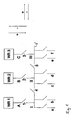
- Fig. 1 schematically shows the parallel operation of three converters on a common electrical system.
- the current or inverters WR 1 , WR 2 and WR 3 convert the DC voltage provided by the batteries or a fuel cell system into alternating voltage or three-phase current.
- the single-phase version is shown here.
- the switches 1 and 5 are closed, so that a common bus bar 6 is formed.
- the switches 1 and 3 are closed, so that the inverters WR 1 and WR 3 jointly feed the electrical system.
- the switch 2 remains open in normal operation, so that the inverter WR 2 is not connected to the grid and is available as a reserve inverter, which is switched on failure of one of the other inverter WR 1 or WR 3 .
- the bus bar 6 is divided into three sections I, II and III or is divisible by opening the switch.
- circuit breakers 1, 2, 3, 4 and 5 are provided which simultaneously detect these values and can report them to a central control device, which is also responsible for opening and closing the switches 1 to 5.
- the switches 1 to 5 are equipped for this purpose with appropriate communication modules.
- the parallel operation of two inverters for example the inverters WR 1 and WR 3 on a common busbar 6 requires a synchronization of the output voltage and frequency. According to the invention, this is done by independent control devices, which are integrated in the inverters, without a higher-level control or direct communication between the inverters is required. In addition, the inverters are in operation equal, ie there are no dependencies according to the master / slave principle.
- the inverters WR 1 , WR 2 and WR 3 have control devices which automatically detect the vehicle electrical system, ie in particular current and voltage at the busbar 6 and regulate the associated inverter WR 1 , WR 2 or WR 3 so that it automatically on the Network synchronized.
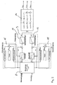
- Fig. 2 shows schematically how this scheme works in principle.
- grid voltages and grid currents are detected by the inverters and in a calculation module 8 of the control unit derived parameters, namely the active and reactive power and frequency and output terminal voltage are calculated based on these characteristics, which serve as reference variables for the subsequent control.
- the calculated frequency of the control of the frequency over the active power controller 10 and the calculated voltage of the regulation of the voltage across the reactive power controller 12.
- Active power controller 6 and reactive power controller 8 are part of a primary controller 9.
- This primary control takes into account static characteristics, which are fixed to the inverter and are stored in a memory of the control device. These are a voltage-reactive power characteristic (Q (U n ) -Statik which is used for voltage regulation, as well as a frequency active power characteristic (P (f) -Statik), which is used for frequency control.
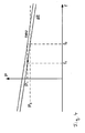
- Fig. 3 is shown as an example of the course of the frequency-effective power statics.
- the course of the voltage-reactive power statics is corresponding. It is important that these are load-dependent characteristics. That is, the characteristic is not a constant, ie horizontal in the diagram, but rather a drop of voltage or frequency with increasing load takes place.
- This embodiment of the characteristics with waste coefficients makes it possible for two inverters with identical control devices to be found in the network so that they can synchronize the grid together.
- the defined statics force the current controller to behave as a controlled synchronous generator.
- the voltage in the network has the frequency f 1 and the amplitude U 1 .
- the associated powers in the network are P 1 and Q 1 (active and reactive power)
- P 1 and Q 1 active and reactive power
- the currents change and the power increases to P 2 and Q 2 , but the voltage amplitude initially remains at U 1 and the frequency remains at f 1 , since the current or inverter itself can not cause any changes of these sizes. It provides a constant output voltage with constant frequency. This change is only possible through the given statics, the P (f) -statics and the Q (U n ) -statics.
- P 1 and Q 1 are determined as reference variables for the active power controller 10 and the reactive power controller 12.
- the controlled variables have changed to P 2 and Q 2 (measured in the network, ie at the busbar 6). This creates a control difference, which is now compensated by the controller.
- the power controllers ie the active power controller 10 and the reactive power controller 12, generate new values for U q * and ⁇ * ( ⁇ *).
- These form the reference variables for the converter output voltage regulator 14, which on the basis of which they set the new output voltages of the inverter U Soll, 1 , U Soll, 2 and U- Soll , 3 , in the case of a three-phase system. From the temporal change of the angle ⁇ * follows the frequency change.
- the voltage in the network changes, the amplitude becomes U 2 , the frequency becomes f 2 .
- a secondary control is provided in addition to the primary control.
- two secondary controls ie two secondary controllers 16, 18 for frequency secondary control (f-secondary control) and voltage secondary control (U secondary control) are provided.
- These secondary controls cause a shift of the statics stored in the primary controller, ie the P (f) statics and the Q (U n ) statics. This is exemplified by the P (f) -statics in FIG. 4 shown.
- the secondary controllers 16 and 18 each have a "testing" module. This causes a shift of the P (f) -statics by f 0, T or the Q (U n ) -statics by U n0, T. The restoration of the frequency or voltage is initiated by the recovery module. The symmetrization then takes place through the Symmetri mecanicsmodul whose principle rule structure in Fig. 5 is shown.
- the starting frequency is initially f 0 and the active power P 0, for example. If the load is now increased to P 1 , the frequency is reduced to f 1 . If, for example, the control device of the first inverter WR 1 reacts first and restores the frequency f 0 , the second inverter WR 3 will interpret this frequency change as a load change and correspondingly reduce its power output. This then leads to the above-mentioned unbalanced load distribution. To compensate for this, the value P sollS is set to 0 during balancing.
- the ratio of the total load to the individual load of the inverter P / P N is greater and vice versa, the value f 0S smaller (larger in absolute terms , but negative range).
- WR 3 wants to lower its frequency due to the symmetrization, in order to increase its performance again. The lowered frequency then leads to an increase in power in WR 1 only to a smaller extent than in WR 2 . The process thus results in a renewed restoration of the frequency.
- the individual inverters are also the failure of another inverter based on the changes in the parameters in the network, d. H. at the busbar 6 and regulate their output voltage according to amplitude and frequency accordingly to maintain target voltage and frequency in the network.
- the circuit in FIG Fig. 1 a protection concept for the network protection explained according to the invention, which can ensure a virtually uninterruptible power supply, especially in the described parallel operation of two or more inverters on a busbar.
- the circuit breaker 1 to 5 are equipped with sensors or sensors which detect the current at the switching point and transmit to a central control device, not shown. This performs an evaluation, which detects faults, ie short circuits in the network and can locate and then selectively open individual of the switches 1 to 5 to disconnect short-circuited power supplies or subnets can.
- This concept ensures the selectivity of the protective devices in the overall network.
- the protection concept is based on the finding that a fault in the network, ie a short circuit can be detected and localized by a specific combination of the short-circuit currents at the individual measuring points. Since the measuring points are integrated here in the circuit breakers, they are located at the points of the line switch. However, separate sensors or transducers could be provided elsewhere.
- the central control device constantly polls the current values determined at the measuring points of the switches 1 to 5 and evaluates them. For this, the measured values be communicated by communicative circuit breakers, for example via a bus system to the central control device. However, other conventionally available communication paths between circuit breakers and controller are also usable.
- Fig. 6 shows the combinations of occurring short-circuit currents in the circuit according to Fig. 1 , wherein in normal operation, the switches 1, 3, 4 and 5 are closed, that is, the sections I, II and III are connected together to form a common busbar 6 and the inverters WR 1 and WR 3 are in operation.
- the inverter WR 2 is kept as a reserve inverter to take over its function in case of failure of one of the other inverters.
- the appropriate switch can be opened.
- a short circuit in the inverter WR 1 ie at location A
- a negative short-circuit current at the measuring point 1 no short-circuit current at the measuring point 2
- a positive short-circuit current at the measuring point 3 a positive short-circuit current at the measuring point 3 and the simple negative short-circuit current at the measuring points 4 respectively certainly.
- the switch 1 must be opened.
- the switches which are to be opened for switching off the power supply with a short circuit are marked by x. In the event that a short circuit occurs in the busbar section II, z. B. the switches 4 and 5 are opened.
- the table as in Fig. 6 is stored in the central control device and this compares the measured at the measuring points 1 to 5 currents with the table. If there is a combination of currents, which is shown in the table, the controller locates in this way a short circuit at a certain point and causes the triggering of the required switch to disconnect the corresponding short-circuited power supplies. These switches are in Fig. 6 marked with x.
- FIG. 6 The table shown concerns the case that inverters WR 1 and WR 3 are in operation. Accordingly, additional tables may be deposited in the event that other combinations of inverters are in operation, the controller, as it opens and closes the switches, knowing which inverters are on the grid and thus accessing the correct table. Furthermore, matrices or tables similar to those in Fig. 6 also for power converter failures, defective switches or non-tripping switches set up. Such tables are in the FIGS. 7 to 9 shown. So is in Fig. 7 which short-circuit currents occur at the measuring points 1 to 5 in the event that one of the power converters WR 1 , WR 2 or WR 3 (power converter 1, Power converter 2 and power converter 3) fails. Again, to eliminate the error again open the switch marked with x, depending on where the short circuit occurs.
- Fig. 8 shows a table which takes into account the case that one of the switches 1 to 4 is defective, wherein in the table in Fig. 8 all five cases, ie switch 1 defective, switch 2 defective, switch 3 defective, switch 4 defective or switch 5 defective, are shown.
- switch 1 defective, switch 2 defective, switch 3 defective, switch 4 defective or switch 5 defective are shown.
- the inverters WR 1 and WR 3 are in operation and the inverter W 2 is switched off as a reserve inverter by opening the switch 2.
- those switches which are to be opened for the individual case of short circuit to disconnect the corresponding subnet marked with x.
- those switches are marked with y, which are to be opened in the event that one of the switches, which should actually trigger, is defective.
- Fig. 9 shows the combination of short-circuit currents in the event of failure of a switch after the release of the other switch involved in the switching operation.
- Fig. 10 schematically shows a suitable program flow in the control device. It starts with the continuous measurement of the currents at the measuring points in the circuit breakers, in Fig. 1 the bodies 1 to 5. If a specific image of short-circuit currents in accordance with the table in Fig. 6 determined in a first step, which switch must be opened to turn off the part of the network with the short circuit, as determined by Fig. 6 is explained. This takes place in step S1, followed by a renewed measuring of the currents, if a short-circuit is still detected, a new table is taken into account in which the already opened switch is taken into account. Based on this new table is then determined again, which switch must be opened. This takes place in step S2, wherein the corresponding switch must be opened with a time delay.
- step S1b a correspondingly changed table is accessed in step S1b, which takes into account the defective switch or converter and the corresponding pictures of the Short-circuit currents or the corresponding distribution of short-circuit currents contains. This table is used to monitor whether a short circuit occurs and, in the event of a short circuit, locate the short circuit and select the switch to open. Thereafter, a renewed measurement of the currents and in the event that the short circuit persists, in step S2b a renewed monitoring using a modified new table corresponding to the step S2.
Claims (15)
- Sous-marin équipé d'un réseau électrique de bord, présentant au moins deux onduleurs (WR1, WR2, WR3) qui alimentent une barre omnibus commune (6), dans lequel chacun des au moins deux onduleurs (WR1, WR2, WR3) est équipé d'un dispositif de régulation indépendant qui est conçu pour la détection de grandeurs caractéristiques électriques en cours sur la barre omnibus (6) et comporte un module de régulation conçu pour réguler la tension de sortie sur la base des grandeurs caractéristiques et/ou de grandeurs caractéristiques dérivées, le module de régulation comprenant un régulateur primaire (9) dans lequel sont mémorisées, pour l'onduleur (WR1, WR2, WR3), des caractéristiques statiques sur la base desquelles sont déterminées les grandeurs pilotes pour le régulateur primaire, et chaque dispositif de régulation étant équipé d'au moins un régulateur secondaire (16, 18) qui, sur la base des grandeurs caractéristiques ou des grandeurs caractéristiques dérivées, opère un déplacement parallèle d'une caractéristique statique stockée dans le régulateur primaire (9) pour atteindre les valeurs de consigne, en particulier de fréquence et de tension pour une puissance donnée, le régulateur secondaire étant doté d'un dispositif d'équilibrage pour l'équilibrage de la répartition de charge.
- Sous-marin selon la revendication 1, dans lequel chaque dispositif de régulation comprend un module de détection destiné à détecter les grandeurs caractéristiques électriques, en particulier des tensions secteur et courants secteur sur la barre omnibus (6).
- Sous-marin selon la revendication 1 ou 2, dans lequel chaque dispositif de régulation comprend un module de calcul (8) destiné à calculer des grandeurs caractéristiques dérivées, en particulier de la puissance active et réactive, ainsi que de la fréquence et de la tension aux bornes de sortie, sur la base des grandeurs caractéristiques électriques détectées.
- Sous-marin selon l'une des revendications précédentes, dans lequel les caractéristiques statiques présentent un diagramme tension-puissance réactive et/ou un diagramme fréquence-puissance active à partir desquels on peut déterminer, en tant que grandeurs pilotes, la puissance réactive et/ou la puissance active en fonction des grandeurs caractéristiques détectées et/ou des grandeurs caractéristiques dérivées.
- Sous-marin selon la revendication 4, dans lequel le régulateur primaire (9) comprend un régulateur de puissance réactive (12) et un régulateur de puissance active (10).
- Sous-marin selon la revendication 5, dans lequel le module de régulation comprend un régulateur de tension de sortie (14) auquel sont transmises, en tant que grandeurs pilotes, les grandeurs de réglage du régulateur de puissance réactive (12) et du régulateur de puissance active (10), en particulier fréquence et tension.
- Sous-marin selon l'une des revendications précédentes, dans lequel le dispositif d'équilibrage détecte le rapport entre la puissance de sortie de l'onduleur (WR1, WR2, WR3) correspondant et la puissance totale sur la barre omnibus (6) et, en fonction d'une variation de ce rapport, opère un déplacement parallèle d'une caractéristique statique stockée dans le régulateur primaire (9) pour atteindre les valeurs de consigne, en particulier de fréquence et de tension, pour une puissance donnée.
- Sous-marin selon l'une des revendications précédentes, dans lequel sont prévus dans le dispositif de régulation deux régulateurs secondaires (16, 18) dont l'un sert à la régulation de fréquence et l'autre à la régulation de tension.
- Sous-marin selon l'une des revendications précédentes, comprenant un réseau électrique de bord subdivisé en plusieurs sous-réseaux (A, B, C, I, II, III) qui sont protégés respectivement par au moins un sectionneur de puissance (1, 2, 3, 4, 5), dans lequel les différents sous-réseaux (A, B, C, I, II, III) sont pourvus de capteurs (1, 2, 3, 4, 5) pour détecter des données caractéristiques des différents sous-réseaux (A, B, C, I, II, III), les capteurs et les sectionneurs de puissance (1, 2, 3, 4, 5) communiquent avec un dispositif de commande commun, et les sectionneurs de puissance (1, 2, 3, 4, 5) peuvent être sélectivement commutés par le dispositif de commande en fonction des données caractéristiques réelles détectées.
- Sous-marin selon la revendication 9, dans lequel les données caractéristiques des différents sous-réseaux (A, B, C, I, II, III) comprennent les courants électriques dans les différents sous-réseaux.
- Sous-marin selon la revendication 9 ou 10, dans lequel est mémorisé, dans le dispositif de commande, au moins un tableau dans lequel, pour chaque cas de court-circuit survenant dans l'un des sous-réseaux (A, B, C, I, II, III), sont mémorisés les courants de court-circuit survenant respectivement dans les différents sous-réseaux (A, B, C, I, II, III) et/ou sur les capteurs (1, 2, 3, 4, 5) associés, ou leur rapport mutuel..
- Sous-marin selon la revendication 11, dans lequel le dispositif de commande est conçu de façon telle que la localisation du cas de court-circuit s'opère par affectation de la combinaison occurrente de courants de court-circuit à l'aide du tableau mémorisé et que le sectionneur de puissance (1, 2, 3, 4, 5) correspondant est commutable ensuite par le dispositif de commande pour isoler le sous-réseau (A, B, C, I, II, III) dans lequel le cas de court-circuit a été localisé.
- Sous-marin selon la revendication 11 ou 12, dans lequel est ou sont mémorisé(s) dans le dispositif de commande un ou plusieurs tableau(x) dans lesquels sont consignés, pour chaque cas de court-circuit dans l'un des sous-réseaux (A, B, C, I, II, III), les courants de court-circuit survenant respectivement dans les différents sous-réseaux (A, B, C, I, II, III) et/ou sur les capteurs associés, ou leur rapport mutuel, dans le cas où un ou plusieurs sectionneurs de puissance (1, 2, 3, 4, 5) sont ouverts.
- Sous-marin selon la revendication 13, dans lequel le dispositif de commande est conçu de façon telle qu'après commutation d'un sectionneur de puissance (1, 2, 3, 4, 5) pour isoler un sous-réseau (A, B, C, I, II, III), on utilise pour les localisations de cas de court-circuit ultérieures, un tableau correspondant qui prend en compte l'état ouvert du sectionneur de puissance.
- Sous-marin selon l'une des revendications 9 à 12, dans lequel les capteurs sont intégrés dans les sectionneurs de puissance (1, 2, 3, 4,5).
Applications Claiming Priority (1)
| Application Number | Priority Date | Filing Date | Title |
|---|---|---|---|
| DE102006059199A DE102006059199B3 (de) | 2006-12-13 | 2006-12-13 | Unterseeboot |
Publications (3)
| Publication Number | Publication Date |
|---|---|
| EP1933451A2 EP1933451A2 (fr) | 2008-06-18 |
| EP1933451A3 EP1933451A3 (fr) | 2009-06-24 |
| EP1933451B1 true EP1933451B1 (fr) | 2011-12-07 |
Family
ID=39185256
Family Applications (1)
| Application Number | Title | Priority Date | Filing Date |
|---|---|---|---|
| EP07019996A Active EP1933451B1 (fr) | 2006-12-13 | 2007-10-12 | Sous-marin avec circuit d'alimentation électrique |
Country Status (6)
| Country | Link |
|---|---|
| EP (1) | EP1933451B1 (fr) |
| KR (1) | KR101109564B1 (fr) |
| AT (1) | ATE536306T1 (fr) |
| DE (1) | DE102006059199B3 (fr) |
| ES (1) | ES2378258T3 (fr) |
| PT (1) | PT1933451E (fr) |
Families Citing this family (7)
| Publication number | Priority date | Publication date | Assignee | Title |
|---|---|---|---|---|
| DE102009043530A1 (de) | 2009-09-30 | 2011-04-07 | Siemens Aktiengesellschaft | Elektrische Antriebswelle und Fahrzeug mit einer derartigen elektrischen Antriebswelle |
| DE102010001333A1 (de) | 2010-01-28 | 2011-08-18 | Airbus Operations GmbH, 21129 | Verfahren und Vorrichtung zum Bereitstellen einer Bordnetz-Wechselspannung bei einem Flugzeug |
| EP2533413B1 (fr) * | 2011-06-09 | 2014-09-17 | Siemens Aktiengesellschaft | Synchronisation d'un onduleur avec un réseau de distribution électrique |
| EP2632012B1 (fr) * | 2012-02-22 | 2016-02-17 | Siemens Aktiengesellschaft | Procédé de synchronisation d'une tension d'alimentation ayant une tension réseau |
| CN105634309B (zh) * | 2014-11-06 | 2018-06-22 | 台达电子工业股份有限公司 | 一种用于逆变系统的控制方法及控制装置 |
| FR3038151A1 (fr) * | 2015-06-25 | 2016-12-30 | Orange | Alimentation electrique d'une charge avec barre de distribution segmentee |
| KR102138402B1 (ko) * | 2016-03-22 | 2020-07-28 | 한국조선해양 주식회사 | 선박용 필드버스 통신 시스템 |
Family Cites Families (9)
| Publication number | Priority date | Publication date | Assignee | Title |
|---|---|---|---|---|
| US3675037A (en) * | 1971-06-01 | 1972-07-04 | Bell Telephone Labor Inc | Technique for synchronous parallel operation of static inverters |
| US5596492A (en) * | 1994-06-14 | 1997-01-21 | Electric Power Research Institute, Inc. | Method and apparatus for de-centralized signal frequency restoration in a distributed UPS system |
| DE9413638U1 (de) * | 1994-08-24 | 1995-12-21 | Siemens Ag | Energieversorgungs- und Antriebsanlage für ein Unterseeboot |
| DE19716826A1 (de) | 1997-04-22 | 1998-11-19 | Stn Atlas Elektronik Gmbh | Stromversorgungsnetz, insbesondere Schiffsbordnetz |
| US7116010B2 (en) * | 2002-09-17 | 2006-10-03 | Wisconsin Alumni Research Foundation | Control of small distributed energy resources |
| DE10325456A1 (de) * | 2003-06-05 | 2004-12-30 | Howaldtswerke Deutsche Werft Ag | Unterseeboot |
| US6803679B1 (en) * | 2003-10-02 | 2004-10-12 | Phoenixtec Power Co., Ltd. | Parallel redundant power system and method for control of the power system |
| DE10353967A1 (de) * | 2003-11-19 | 2005-07-07 | Siemens Ag | Energieerzeugungs-, Verteilungs- und Bordstromversorgungssystem für emissionsarme Überwasser-Marine(Navy)-Schiffe unterschiedlicher Klassen und Größen |
| DE102005008766B3 (de) * | 2005-02-25 | 2006-11-16 | Siemens Ag | U-Boot-Gleichstromnetz |
-
2006
- 2006-12-13 DE DE102006059199A patent/DE102006059199B3/de not_active Expired - Fee Related
-
2007
- 2007-10-12 AT AT07019996T patent/ATE536306T1/de active
- 2007-10-12 PT PT07019996T patent/PT1933451E/pt unknown
- 2007-10-12 ES ES07019996T patent/ES2378258T3/es active Active
- 2007-10-12 EP EP07019996A patent/EP1933451B1/fr active Active
- 2007-10-29 KR KR1020070108853A patent/KR101109564B1/ko active IP Right Grant
Also Published As
| Publication number | Publication date |
|---|---|
| KR20080055617A (ko) | 2008-06-19 |
| KR101109564B1 (ko) | 2012-02-28 |
| DE102006059199B3 (de) | 2008-04-17 |
| ES2378258T3 (es) | 2012-04-10 |
| PT1933451E (pt) | 2012-03-20 |
| EP1933451A3 (fr) | 2009-06-24 |
| ATE536306T1 (de) | 2011-12-15 |
| EP1933451A2 (fr) | 2008-06-18 |
Similar Documents
| Publication | Publication Date | Title |
|---|---|---|
| EP1933451B1 (fr) | Sous-marin avec circuit d'alimentation électrique | |
| DE102010001333A1 (de) | Verfahren und Vorrichtung zum Bereitstellen einer Bordnetz-Wechselspannung bei einem Flugzeug | |
| EP2608355B1 (fr) | Dispositif d'alimentation en courant sans interruption de consommateurs électriques et procédé de fonctionnement du dispositif | |
| DE112019003016T5 (de) | Ferndifferentialschutzvorrichtung | |
| DE112017002454T5 (de) | Relaisvorrichtung | |
| WO2011131655A2 (fr) | Système de production de courant et procédé destiné à faire fonctionner un tel système | |
| DE102011000394A1 (de) | Lokale Energieversorgungsanlage | |
| DE102012102766B3 (de) | Netzersatzanlage und Erdungseinrichtung für eine Netzersatzanlage | |
| EP2912741B1 (fr) | Onduleur, procédé faire fonctionner un onduleur et installation d'alimentation en énergie comprenant un onduleur | |
| DE102018105826B4 (de) | Elektrisches versorgungssystem und verfahren | |
| EP3361593B1 (fr) | Alimentation électrique sans interruption pour charges électriques | |
| WO2014096009A1 (fr) | Installation auxiliaire d'alimentation et procédé de séparation d'un réseau local de distribution d'énergie d'un réseau supérieur d'alimentation en énergie | |
| EP2070172A1 (fr) | Système de protection redondant et procédé de surveillance redondante d'objets protégés dans un réseau d'alimentation en énergie électrique | |
| EP3586418B1 (fr) | Réseau de tension électrique continue à haute redondance | |
| WO2021144103A1 (fr) | Dispositif de changement, kit de rattrapage et procédé pour fournir de l'énergie électrique à une charge | |
| DE102019125296B4 (de) | Verfahren zum detektieren eines kurzschlusses einer dc-last und gleichrichter mit einem derartigen verfahren | |
| EP1808946B1 (fr) | Procédé de surveillance d'un câble pouvant être déconnecté dans un réseau électrique, dispositif de surveillance correspondant tout comme système de surveillance | |
| DE112017002553T5 (de) | Leistungswandlersystem für eine Stromversorgungssystem-Verbindung | |
| WO2023227342A1 (fr) | Procédé de prémagnétisation d'un transformateur moyenne tension, unité de commande et système d'électrolyse | |
| WO2021037557A1 (fr) | Système d'alimentation sans coupure | |
| CH682435A5 (de) | Vorrichtung zur Sicherung des unterbrechungsfreien Betriebes von Umrichtern. | |
| EP4104270A1 (fr) | Bloc d'alimentation redondant destiné en particulier à un centre de données, et procédé et programme informatique pour le faire fonctionner | |
| EP4186136A1 (fr) | Onduleur à unité de commutation bistable | |
| EP4104269A1 (fr) | Alimentation électrique redondante, en particulier destinée à un centre de données, et procédé et programme informatique correspondants | |
| DE102009035166A1 (de) | Verfahren zum Betreiben eines elektrischen Energieversorgungsnetzes |
Legal Events
| Date | Code | Title | Description |
|---|---|---|---|
| PUAI | Public reference made under article 153(3) epc to a published international application that has entered the european phase |
Free format text: ORIGINAL CODE: 0009012 |
|
| AK | Designated contracting states |
Kind code of ref document: A2 Designated state(s): AT BE BG CH CY CZ DE DK EE ES FI FR GB GR HU IE IS IT LI LT LU LV MC MT NL PL PT RO SE SI SK TR |
|
| AX | Request for extension of the european patent |
Extension state: AL BA HR MK RS |
|
| PUAL | Search report despatched |
Free format text: ORIGINAL CODE: 0009013 |
|
| AK | Designated contracting states |
Kind code of ref document: A3 Designated state(s): AT BE BG CH CY CZ DE DK EE ES FI FR GB GR HU IE IS IT LI LT LU LV MC MT NL PL PT RO SE SI SK TR |
|
| AX | Request for extension of the european patent |
Extension state: AL BA HR MK RS |
|
| 17P | Request for examination filed |
Effective date: 20090710 |
|
| 17Q | First examination report despatched |
Effective date: 20090807 |
|
| AKX | Designation fees paid |
Designated state(s): AT BE BG CH CY CZ DE DK EE ES FI FR GB GR HU IE IS IT LI LT LU LV MC MT NL PL PT RO SE SI SK TR |
|
| REG | Reference to a national code |
Ref country code: DE Ref legal event code: R079 Ref document number: 502007008795 Country of ref document: DE Free format text: PREVIOUS MAIN CLASS: H02M0007493000 Ipc: B63G0008080000 |
|
| RIC1 | Information provided on ipc code assigned before grant |
Ipc: B63G 8/08 20060101AFI20110502BHEP |
|
| GRAP | Despatch of communication of intention to grant a patent |
Free format text: ORIGINAL CODE: EPIDOSNIGR1 |
|
| GRAS | Grant fee paid |
Free format text: ORIGINAL CODE: EPIDOSNIGR3 |
|
| GRAA | (expected) grant |
Free format text: ORIGINAL CODE: 0009210 |
|
| AK | Designated contracting states |
Kind code of ref document: B1 Designated state(s): AT BE BG CH CY CZ DE DK EE ES FI FR GB GR HU IE IS IT LI LT LU LV MC MT NL PL PT RO SE SI SK TR |
|
| REG | Reference to a national code |
Ref country code: GB Ref legal event code: FG4D Free format text: NOT ENGLISH |
|
| REG | Reference to a national code |
Ref country code: CH Ref legal event code: EP |
|
| REG | Reference to a national code |
Ref country code: IE Ref legal event code: FG4D Free format text: LANGUAGE OF EP DOCUMENT: GERMAN |
|
| REG | Reference to a national code |
Ref country code: DE Ref legal event code: R096 Ref document number: 502007008795 Country of ref document: DE Effective date: 20120209 |
|
| REG | Reference to a national code |
Ref country code: NL Ref legal event code: T3 |
|
| REG | Reference to a national code |
Ref country code: PT Ref legal event code: SC4A Free format text: AVAILABILITY OF NATIONAL TRANSLATION Effective date: 20120307 Ref country code: SE Ref legal event code: TRGR |
|
| REG | Reference to a national code |
Ref country code: ES Ref legal event code: FG2A Ref document number: 2378258 Country of ref document: ES Kind code of ref document: T3 Effective date: 20120410 |
|
| REG | Reference to a national code |
Ref country code: GR Ref legal event code: EP Ref document number: 20120400330 Country of ref document: GR Effective date: 20120322 |
|
| PG25 | Lapsed in a contracting state [announced via postgrant information from national office to epo] |
Ref country code: LT Free format text: LAPSE BECAUSE OF FAILURE TO SUBMIT A TRANSLATION OF THE DESCRIPTION OR TO PAY THE FEE WITHIN THE PRESCRIBED TIME-LIMIT Effective date: 20111207 |
|
| LTIE | Lt: invalidation of european patent or patent extension |
Effective date: 20111207 |
|
| PG25 | Lapsed in a contracting state [announced via postgrant information from national office to epo] |
Ref country code: SI Free format text: LAPSE BECAUSE OF FAILURE TO SUBMIT A TRANSLATION OF THE DESCRIPTION OR TO PAY THE FEE WITHIN THE PRESCRIBED TIME-LIMIT Effective date: 20111207 Ref country code: LV Free format text: LAPSE BECAUSE OF FAILURE TO SUBMIT A TRANSLATION OF THE DESCRIPTION OR TO PAY THE FEE WITHIN THE PRESCRIBED TIME-LIMIT Effective date: 20111207 |
|
| PG25 | Lapsed in a contracting state [announced via postgrant information from national office to epo] |
Ref country code: CY Free format text: LAPSE BECAUSE OF FAILURE TO SUBMIT A TRANSLATION OF THE DESCRIPTION OR TO PAY THE FEE WITHIN THE PRESCRIBED TIME-LIMIT Effective date: 20111207 |
|
| REG | Reference to a national code |
Ref country code: IE Ref legal event code: FD4D |
|
| PG25 | Lapsed in a contracting state [announced via postgrant information from national office to epo] |
Ref country code: CZ Free format text: LAPSE BECAUSE OF FAILURE TO SUBMIT A TRANSLATION OF THE DESCRIPTION OR TO PAY THE FEE WITHIN THE PRESCRIBED TIME-LIMIT Effective date: 20111207 Ref country code: EE Free format text: LAPSE BECAUSE OF FAILURE TO SUBMIT A TRANSLATION OF THE DESCRIPTION OR TO PAY THE FEE WITHIN THE PRESCRIBED TIME-LIMIT Effective date: 20111207 Ref country code: BG Free format text: LAPSE BECAUSE OF FAILURE TO SUBMIT A TRANSLATION OF THE DESCRIPTION OR TO PAY THE FEE WITHIN THE PRESCRIBED TIME-LIMIT Effective date: 20120307 Ref country code: SK Free format text: LAPSE BECAUSE OF FAILURE TO SUBMIT A TRANSLATION OF THE DESCRIPTION OR TO PAY THE FEE WITHIN THE PRESCRIBED TIME-LIMIT Effective date: 20111207 Ref country code: IE Free format text: LAPSE BECAUSE OF FAILURE TO SUBMIT A TRANSLATION OF THE DESCRIPTION OR TO PAY THE FEE WITHIN THE PRESCRIBED TIME-LIMIT Effective date: 20111207 Ref country code: IS Free format text: LAPSE BECAUSE OF FAILURE TO SUBMIT A TRANSLATION OF THE DESCRIPTION OR TO PAY THE FEE WITHIN THE PRESCRIBED TIME-LIMIT Effective date: 20120407 |
|
| PG25 | Lapsed in a contracting state [announced via postgrant information from national office to epo] |
Ref country code: PL Free format text: LAPSE BECAUSE OF FAILURE TO SUBMIT A TRANSLATION OF THE DESCRIPTION OR TO PAY THE FEE WITHIN THE PRESCRIBED TIME-LIMIT Effective date: 20111207 Ref country code: RO Free format text: LAPSE BECAUSE OF FAILURE TO SUBMIT A TRANSLATION OF THE DESCRIPTION OR TO PAY THE FEE WITHIN THE PRESCRIBED TIME-LIMIT Effective date: 20111207 |
|
| PLBE | No opposition filed within time limit |
Free format text: ORIGINAL CODE: 0009261 |
|
| STAA | Information on the status of an ep patent application or granted ep patent |
Free format text: STATUS: NO OPPOSITION FILED WITHIN TIME LIMIT |
|
| PG25 | Lapsed in a contracting state [announced via postgrant information from national office to epo] |
Ref country code: DK Free format text: LAPSE BECAUSE OF FAILURE TO SUBMIT A TRANSLATION OF THE DESCRIPTION OR TO PAY THE FEE WITHIN THE PRESCRIBED TIME-LIMIT Effective date: 20111207 |
|
| 26N | No opposition filed |
Effective date: 20120910 |
|
| REG | Reference to a national code |
Ref country code: DE Ref legal event code: R097 Ref document number: 502007008795 Country of ref document: DE Effective date: 20120910 |
|
| REG | Reference to a national code |
Ref country code: NL Ref legal event code: SD Effective date: 20130312 |
|
| REG | Reference to a national code |
Ref country code: DE Ref legal event code: R081 Ref document number: 502007008795 Country of ref document: DE Owner name: THYSSENKRUPP MARINE SYSTEMS GMBH, DE Free format text: FORMER OWNER: HOWALDTSWERKE-DEUTSCHE WERFT GMBH, 24143 KIEL, DE Effective date: 20130206 |
|
| REG | Reference to a national code |
Ref country code: FR Ref legal event code: CD Owner name: THYSSENKRUPP MARINE SYSTEMS GMBH Effective date: 20130313 |
|
| REG | Reference to a national code |
Ref country code: NL Ref legal event code: TD Effective date: 20130417 |
|
| BERE | Be: lapsed |
Owner name: HOWALDTSWERKE-DEUTSCHE WERFT G.M.B.H. Effective date: 20121031 |
|
| PG25 | Lapsed in a contracting state [announced via postgrant information from national office to epo] |
Ref country code: MC Free format text: LAPSE BECAUSE OF NON-PAYMENT OF DUE FEES Effective date: 20121031 |
|
| REG | Reference to a national code |
Ref country code: CH Ref legal event code: PL |
|
| PG25 | Lapsed in a contracting state [announced via postgrant information from national office to epo] |
Ref country code: FI Free format text: LAPSE BECAUSE OF FAILURE TO SUBMIT A TRANSLATION OF THE DESCRIPTION OR TO PAY THE FEE WITHIN THE PRESCRIBED TIME-LIMIT Effective date: 20111207 |
|
| PG25 | Lapsed in a contracting state [announced via postgrant information from national office to epo] |
Ref country code: CH Free format text: LAPSE BECAUSE OF NON-PAYMENT OF DUE FEES Effective date: 20121031 Ref country code: LI Free format text: LAPSE BECAUSE OF NON-PAYMENT OF DUE FEES Effective date: 20121031 Ref country code: BE Free format text: LAPSE BECAUSE OF NON-PAYMENT OF DUE FEES Effective date: 20121031 |
|
| REG | Reference to a national code |
Ref country code: ES Ref legal event code: PC2A Owner name: THYSSENKRUPP MARINE SYSTEMS GMBH Effective date: 20130912 |
|
| PG25 | Lapsed in a contracting state [announced via postgrant information from national office to epo] |
Ref country code: MT Free format text: LAPSE BECAUSE OF FAILURE TO SUBMIT A TRANSLATION OF THE DESCRIPTION OR TO PAY THE FEE WITHIN THE PRESCRIBED TIME-LIMIT Effective date: 20111207 |
|
| REG | Reference to a national code |
Ref country code: AT Ref legal event code: MM01 Ref document number: 536306 Country of ref document: AT Kind code of ref document: T Effective date: 20121031 |
|
| PG25 | Lapsed in a contracting state [announced via postgrant information from national office to epo] |
Ref country code: AT Free format text: LAPSE BECAUSE OF NON-PAYMENT OF DUE FEES Effective date: 20121031 |
|
| PG25 | Lapsed in a contracting state [announced via postgrant information from national office to epo] |
Ref country code: LU Free format text: LAPSE BECAUSE OF NON-PAYMENT OF DUE FEES Effective date: 20121012 |
|
| PG25 | Lapsed in a contracting state [announced via postgrant information from national office to epo] |
Ref country code: HU Free format text: LAPSE BECAUSE OF FAILURE TO SUBMIT A TRANSLATION OF THE DESCRIPTION OR TO PAY THE FEE WITHIN THE PRESCRIBED TIME-LIMIT Effective date: 20071012 |
|
| REG | Reference to a national code |
Ref country code: DE Ref legal event code: R084 Ref document number: 502007008795 Country of ref document: DE |
|
| REG | Reference to a national code |
Ref country code: DE Ref legal event code: R084 Ref document number: 502007008795 Country of ref document: DE Effective date: 20150206 |
|
| REG | Reference to a national code |
Ref country code: FR Ref legal event code: PLFP Year of fee payment: 9 |
|
| REG | Reference to a national code |
Ref country code: FR Ref legal event code: PLFP Year of fee payment: 10 |
|
| REG | Reference to a national code |
Ref country code: FR Ref legal event code: PLFP Year of fee payment: 11 |
|
| REG | Reference to a national code |
Ref country code: FR Ref legal event code: PLFP Year of fee payment: 12 |
|
| REG | Reference to a national code |
Ref country code: DE Ref legal event code: R081 Ref document number: 502007008795 Country of ref document: DE Owner name: THYSSENKRUPP MARINE SYSTEMS GMBH, DE Free format text: FORMER OWNER: THYSSENKRUPP MARINE SYSTEMS GMBH, 24143 KIEL, DE |
|
| P01 | Opt-out of the competence of the unified patent court (upc) registered |
Effective date: 20230530 |
|
| PGFP | Annual fee paid to national office [announced via postgrant information from national office to epo] |
Ref country code: PT Payment date: 20230928 Year of fee payment: 17 Ref country code: NL Payment date: 20231019 Year of fee payment: 17 |
|
| PGFP | Annual fee paid to national office [announced via postgrant information from national office to epo] |
Ref country code: GR Payment date: 20231020 Year of fee payment: 17 Ref country code: GB Payment date: 20231020 Year of fee payment: 17 |
|
| PGFP | Annual fee paid to national office [announced via postgrant information from national office to epo] |
Ref country code: ES Payment date: 20231222 Year of fee payment: 17 |
|
| PGFP | Annual fee paid to national office [announced via postgrant information from national office to epo] |
Ref country code: TR Payment date: 20231009 Year of fee payment: 17 Ref country code: SE Payment date: 20231019 Year of fee payment: 17 Ref country code: IT Payment date: 20231026 Year of fee payment: 17 Ref country code: FR Payment date: 20231023 Year of fee payment: 17 Ref country code: DE Payment date: 20231020 Year of fee payment: 17 |